Article

Analysis of Different Winding Configuration on Electromagnetic Performance of Novel Dual Three-Phase Outer-Rotor Flux-Switching Permanent Magnet Machine for Oscillating Water Column Wave Energy Generation

1
Institute of Electrical Engineering, Chinese Academy of Sciences, Beijing 100190, China
2
School of Electronic, Electrical and Communication Engineering, University of Chinese Academy of Sciences, Beijing 100049, China
*
Authors to whom correspondence should be addressed.
Energies 2025, 18(5), 1021; https://doi.org/10.3390/en18051021
Submission received: 30 December 2024 / Revised: 26 January 2025 / Accepted: 8 February 2025 / Published: 20 February 2025
(This article belongs to the Special Issue Ocean Energy Conversion and Magnetohydrodynamic Power Systems)

Abstract

:
In this article, we propose, for the first time, to apply the flux-switching permanent magnet (OR-FSPM) generator to the oscillating water column wave energy conversion (OWC-WEC), and a novel dual three-phase 24-slot/46-pole OR-FSPM generator for OWC-WEC is designed and analyzed. The feasible phase-shift angle (PH-Angle) between the two sets of windings, namely 0°, 30° and 60°, is analyzed. The electromagnetic performance of the generator under three winding configurations is investigated, including PM flux linkage, back electromotive force (EMF), open-circuit rectified voltage, inductance, cogging torque, electromagnetic torque and unbalanced magnetic force (UMF). The prototype is manufactured, and the experimental results are consistent with that of the finite-element analysis (FEA) results. The generator with 0° and 60° PH-Angle winding configuration has stronger fault tolerance. When the 30° PH-Angle winding configuration is adopted, it has the maximum back-EMF fundamental amplitude, maximum average electromagnetic torque and the minimum torque ripple, and there is no UMF when a single set of windings is running. Therefore, the proposed novel OR-FSPM generator with 30° PH-Angle winding configuration is more suitable for OWC-WEC.

1. Introduction

This research on stator-permanent-magnet (stator-PM) brushless machines can be traced back to 1955 [1]. The stator-PM machines have high efficiency, high power density and better heat dissipation conditions, so they have been widely studied [2]. The stator-PM machines can usually be divided into three types, namely flux-reversal PM (FRPM) machine, flux-switching PM (FSPM) machine and doubly salient PM (DSPM) machine. Compared with the other two types of machines, the FSPM machine has attracted much attention due to better sinusoidal flux linkage and back-EMF waveforms and higher power density. It is widely used in aerospace [3], wind power generation [4], electric vehicles [5], electromagnetic launch [6], wave energy conversion [7,8,9], and so on.
The global fossil energy is being gradually depleted, the demand for electricity is increasing year by year, and the climate problem is deteriorating. The exploitation of the huge resources of wave energy might be a valuable solution to the above problems. OWC-WEC consists of three main components: air chamber, air turbine and generator. OWC-WEC drives the generator to generate electricity through reciprocating airflow, which is similar to the operation principle of wind power generation systems. Compared with other types of wave energy conversion devices, the turbine-generator unit of the oscillating water column wave energy converter (OWC-WEC) is entirely above the sea surface; is not directly impacted by waves; and features a simple structure, relatively high reliability and low construction, operation and maintenance costs [10]. OWC-WEC seems to be one of the most promising technologies among WECs [11], which utilize the coupling between the wave motions and an air chamber to dive an air turbine. In [12], the doubly fed induction generator (DFIG) was used for OWC-WEC. The main drawback of the DFIG is that the rotor terminals are available through brushes or slip rings that degrade over time. Although brushless DFIGs are available, the control issue and the optimization of this kind of machine have prevented its widespread application. The squirrel-cage induction generator (SCIG) can dispense with the brushes or slip rings, but its conversion efficiency is relatively low. The permanent magnet synchronous generator (PMSG) is one of the most adopted solutions for OWC-WEC due to its higher efficiency with respect to the induction generator [11].
Using multiphase winding instead of three-phase winding can reduce the power distribution of each phase winding while improving fault-tolerant ability and control flexibility. In [13], the multiphase FSPM machine and the three-phase one applied in aerospace are compared, showing that the multiphase FSPM machine has more advantages in torque capability and fault tolerance. Three nine-phase FSPM wind power generators with different slot-pole combinations were analyzed and compared [14]. Ref. [15] proposed a twelve-phase FSPM wind power generator topology and investigated the influence of different rotor poles on the electromagnetic performance. In [16], a novel 12-slot/13-pole six-phase axial FSPM machine is proposed. The electromagnetic performance of an axial FSPM machine with two different winding configurations was analyzed, and the prototype was manufactured and tested. However, these studies have been focused on the inner-rotor (IR) type, axial flux type and linear type and less on the OR-FSPM machine.
In [17], an OR-FSPM machine with traditional rectangular PMs was proposed for light traction applications. However, the stator teeth with low magnetic density and the tail of the PMs will greatly occupy the slot space of the OR-FSPM machine, which is not abundant. A 12-slot/22-pole OR-FSPM machine is proposed [18]. Its PMs and iron teeth are wedge-shaped. It can improve the problem that the bottom of PMs and iron teeth occupy the armature winding space. A 48-slot/44-pole three-phase OR-FSPM machine with PMs on the rotor is proposed [19], and its rotor poles and PMs are supported by nonmagnetic units. A 36-slot/34-pole OR-FSPM machine for electric vehicle applications was designed and analyzed in [20]. An outer rotor double FSPM excited generator is designed and optimized for wind power generation in [21]. However, its PMs are located on the rotor, resulting in poor heat dissipation capacity. The five-phase OR-FSPM machines with different topologies and winding configurations are compared for in-wheel traction [22,23]. The aforementioned achievements show that the OR-FSPM machines are popular in the application of in-wheel traction, and there are still relatively few studies on multiphase OR-FSPM machines.
The FSPM generator has been proved suitable for wind power generation systems. In [8,9], the FSPM linear generator is applied in wave energy generation. Its performance is superior to that of the traditional PM linear generator, which proves that the FSPM generator has good application prospects in the field of wave energy conversion. Based on the above research findings, we think the FSPM generator can also be used in OWC-WEC. The OR-FSPM generator can be placed in the shroud of the air turbine to facilitate the integration of the outer rotor and the moving blade hub of the air turbine, and this avoids the adverse effects of external generators on reciprocating airflow. At the same time, the OWC-WEC needs to have high reliability to achieve long-term stable operation at sea. The rotor structure of the FSPM generator is simple and reliable; its PMs are located on the stator; and there is no risk of the magnets falling off, which helps to improve the reliability of the system. Certainly, the OR-FSPM machine has better application prospects in the OWC-WEC, which requires strong fault-tolerance, high torque capability and high efficiency. Therefore, a novel 24-slot/46-pole dual three-phase OR-FSPM machine for OWC-WEC is proposed. Theoretically, compared with other PM generators, the proposed topology exhibits lower cogging torque, which is conducive to starting, and lower torque ripple, which enables the generator set to operate more smoothly. Similarly, the novel machine can also be applied to wind power generation and electric vehicles. Different winding configurations influence the electrical machine’s internal and external characteristics by influencing the armature reaction field [24]. The electromagnetic performance of the novel 24-slot/46-pole dual three-phase OR-FSPM machine with three different winding configurations for OWC-WEC is studied. Its topology is shown in Figure 1.
In the following, the topology of the novel dual three-phase OR-FSPM machine with three different phase-shift angle winding configurations is introduced in Section 2. Section 3 studies the electromagnetic performance of the machine by finite-element analysis (FEA), including open-circuit PM flux linkage, back electromotive force (EMF), open-circuit rectified voltage, torque characteristic, inductance and unbalanced magnetic force (UMF). In Section 4, the prototype is tested and compared with the results of finite-element analysis. Finally, a 24-slot/46-pole dual three-phase OR-FSPM machine is prototyped and tested.

2. OR-FSPM Generator Topology and Winding Configuration
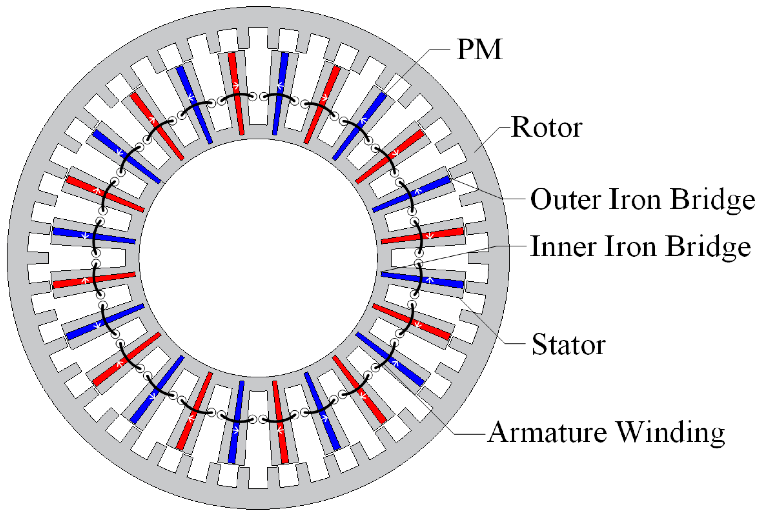
2.1. Topology

The proposed dual three-phase OR-FSPM generator topology is shown in Figure 1. The stator consists of 24 U-shaped core units, 24 circumferentially interlaced magnetized PMs and 24 concentrated windings. The PMs are clamped in two stator teeth to form a stator unit, and the concentrated windings are wound on the stator units. The rotor is simply composed of 46 salient iron teeth without PMs and windings. The dual three-phase OR-FSPM generator not only has the advantages of strong reliability and better thermal dissipation capability of the traditional FSPM machine but also has the freedom of design of multiphase machines, which can use different winding configurations and fault-tolerant control strategies. In order to simplify the manufacturing, iron bridges are added to the inner diameter of the stator and the periphery of the PMs to facilitate the stamping of the stator sheets and the insertion of the PMs into the stator. The key structure parameters of the 24-slot/46-pole OR-FSPM machine are shown in Table 1.
The stator slot number Ns is the same as the conventional IR-FSPM machine, which is determined by phase number m and coil number Nc. However, the number of rotor poles Nr should not be close to the number of slots Ns. The relationship between the number of slots and the number of rotor poles of the OR-FSPM machine can be expressed as
Ns = m × Nc
Nr = 2Ns ± k
where k is the positive integer. If k is an even number, the UMF can be theoretically eliminated.

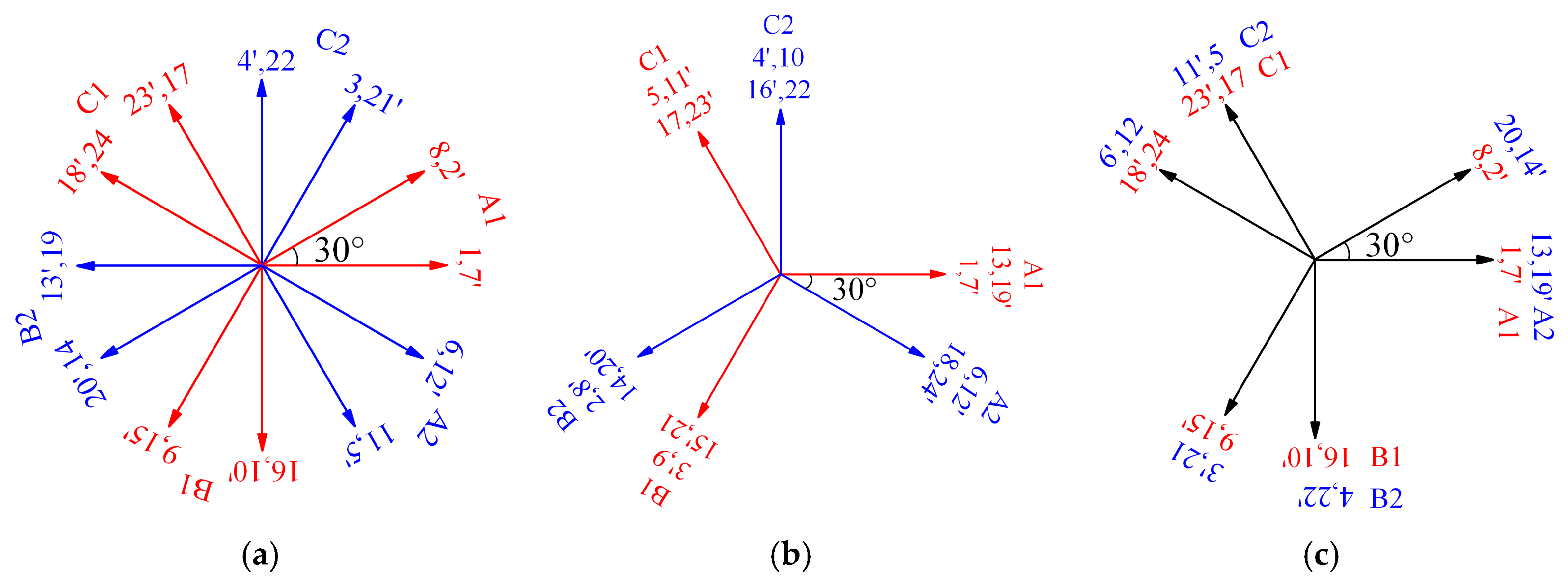
2.2. Winding Configuration

The phase difference α between the back EMF vectors of two adjacent coils can be expressed as
α = 2πNr/Ns + π
According to the arrangement of the coil back EMF phasors, the spatial phase-shift angle θs between the two groups of three-phase windings of the dual three-phase OR-FSPM machine can be divided into the following three cases, as shown in Figure 2. The phase windings of θs = 60° and θs = 0° contained the same coils. However, the difference is that the coil polarity of the second set of three-phase windings (A2, B2, C2) in θs = 0° is opposite to that of θs = 60°.
The winding coefficient kω is obtained by multiplying the distribution coefficient kd and coil pitch coefficient kp. It was used to evaluate the electromagnetic performance of the machine. The calculation method of the kd and kp have been given in [25]. The kd can be expressed as
kd = sin(υqα/2)/(qsin(υα/2))
where q is the number of EMF phasors per phase and υ is the harmonic number.
Furthermore, the coil pitch coefficient kp can be expressed as
kp = cos(π(NrNs)/Ns)
Hence, the winding coefficient kω is expressed as
kω = kdkp
The winding coefficients of the dual three-phase OR-FSPM machine with three winding configurations are calculated, as listed in Table 2. The winding coefficient of θs = 30° winding configuration is the largest; hence, the winding configuration can generate higher electromagnetic torque.

3. Electromagnetic Characteristic Analysis

In this section, the electromagnetic performance of the generator with three winding configurations is compared and studied by 2-D FEA, including radial flux density, phase back EMF, open-circuit rectified voltage, torque capability, inductance and unbalance magnetic force (UMF).

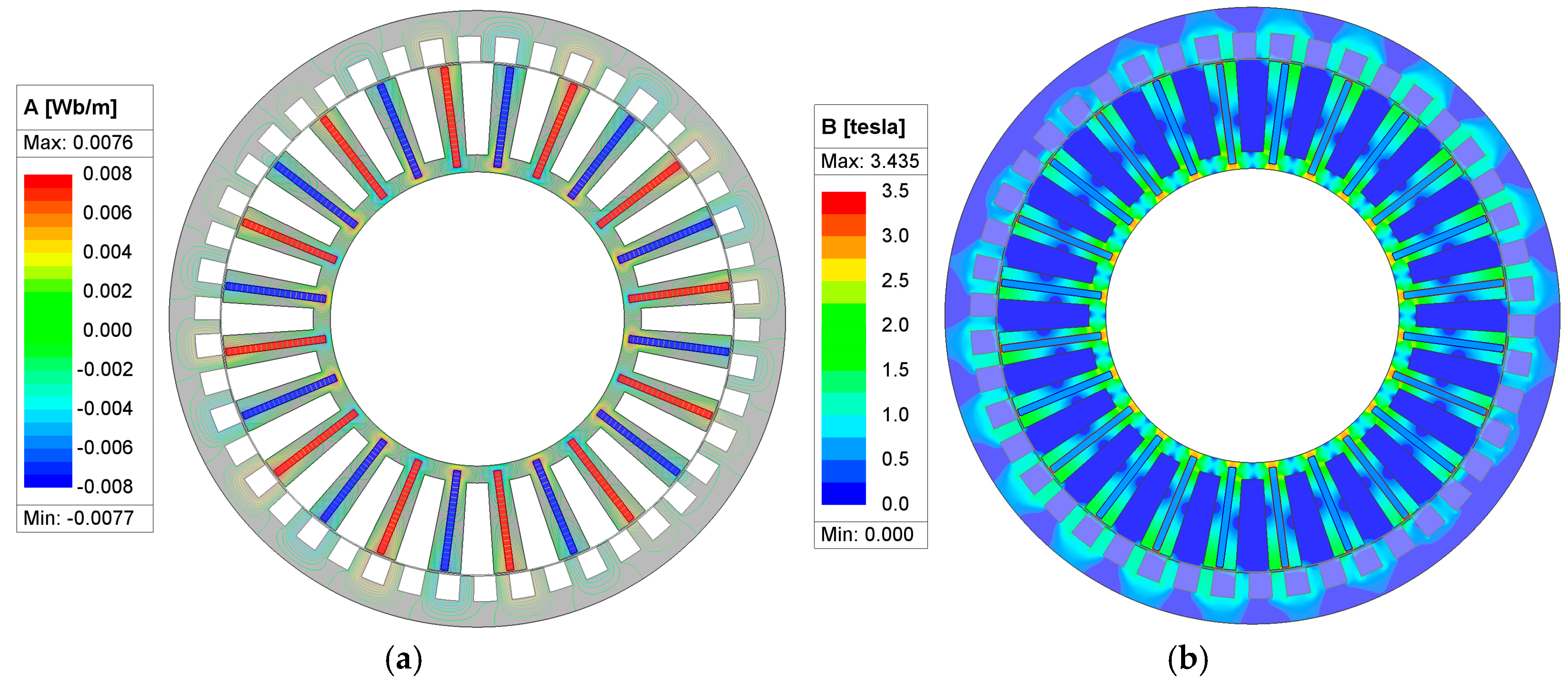
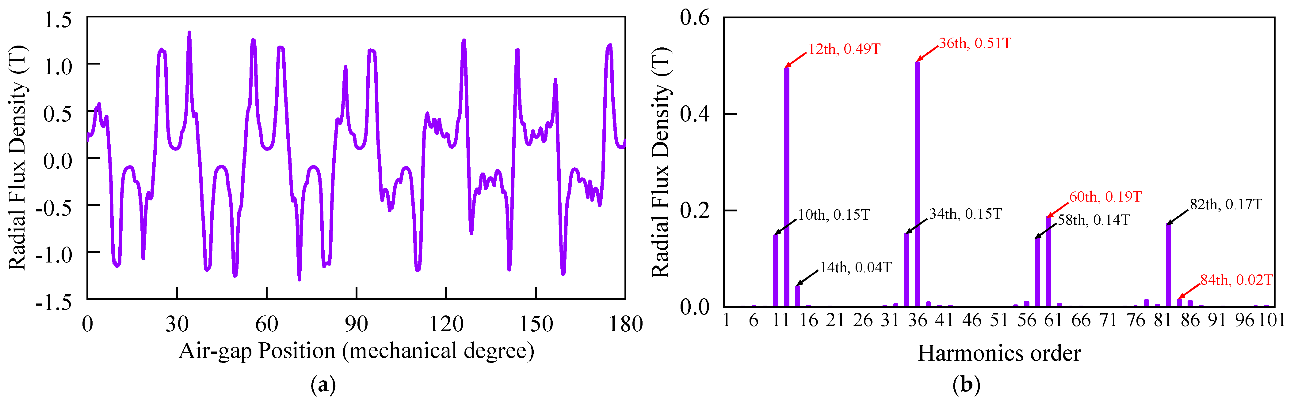
3.1. PM Field Distribution and Air-Gap Flux Density

Due to the same structural parameters, the magnetic field distribution of the three winding configurations is exactly identical. The magnetic lines of force are evenly distributed. Because of the existence of the iron bridge, the magnetic flux leakage is obvious. The PM field distribution is shown in Figure 3.
The air gap is the main place for electromechanical energy exchange, and the air gap flux density reflects the degree of exchange of magnetic field energy of the machine. Based on finite-element analysis, the open-circuit radial air-gap flux density and its harmonic analysis of the 24-slot/46-pole OR-FSPM generator are shown in Figure 4. The maximum is 1.3 T due to the flux-focusing effect. According to the modulation theory of air-gap magnetic field, the 10th, 14th, 34th, 58th and 82nd harmonics are modulated by the permeance of the salient rotor permeance. The 12th, 36th, 60th and 84th harmonics are directly generated by the permanent magnet magnetomotive force [26].

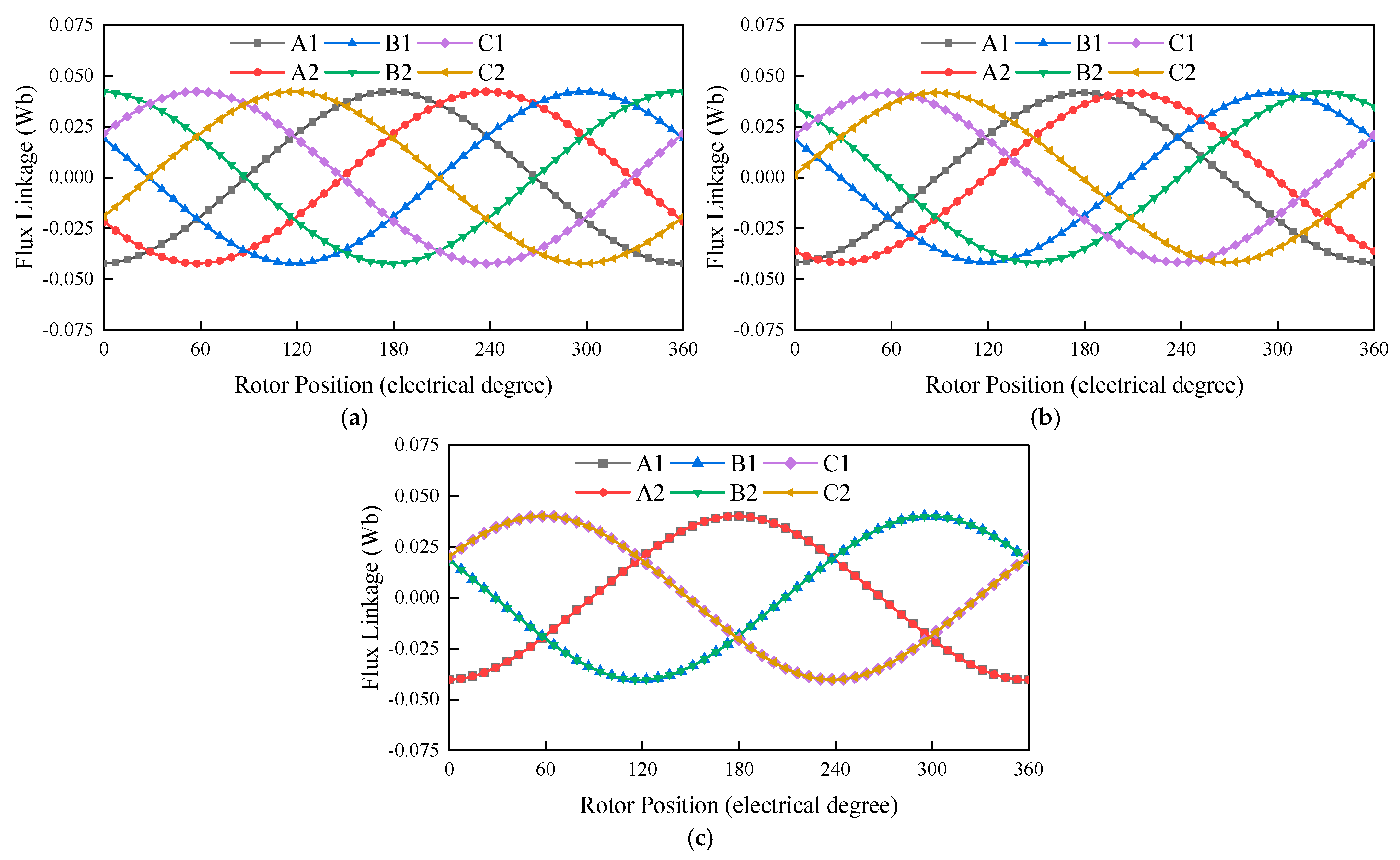
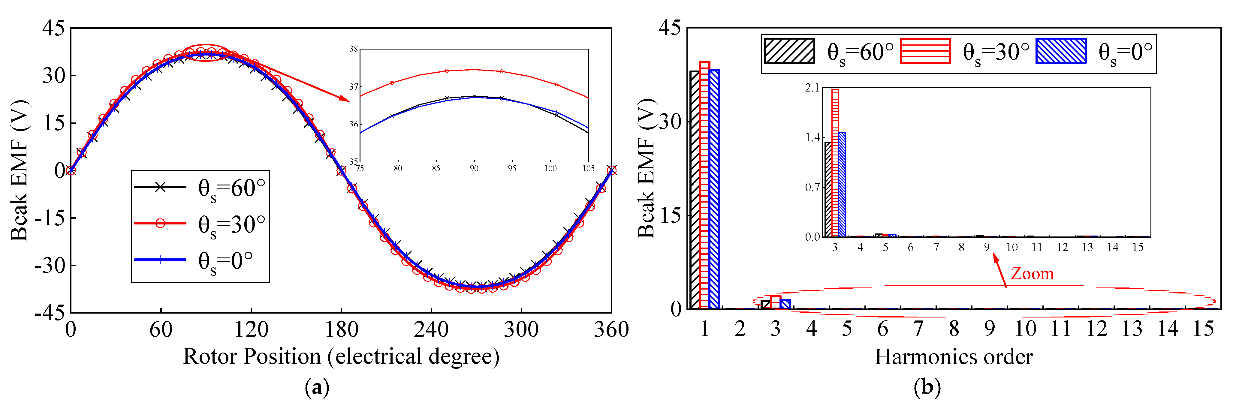
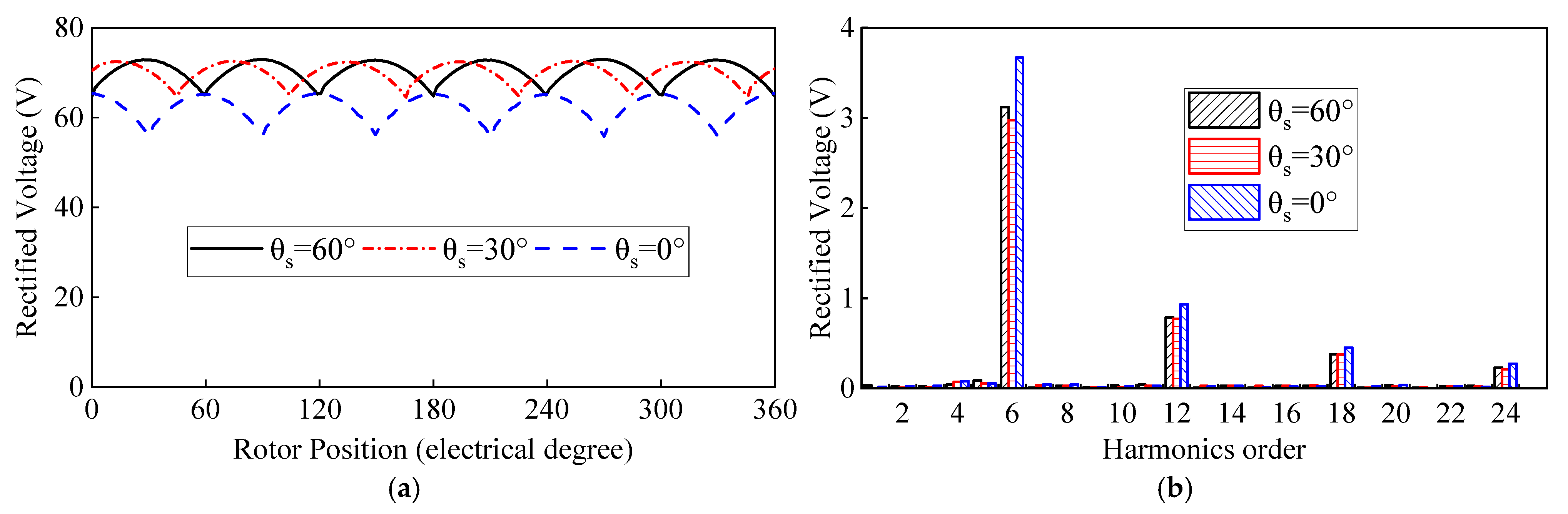
3.2. PM Flux Linkage, Back EMF and Rectified Voltage

The open-circuit PM flux linkages of the machine with three winding configurations are shown in Figure 5, and both of them are highly symmetrical and sinusoidal. The difference between the three-phase flux linkage is 120° electrical degree. The difference between the two sets of three-phase windings is 60°, 30° and 0° electrical degree, respectively.
The A1-phase back EMF and harmonics analysis of the 24-slot/46-pole OR-FSPM generator under the rated speed are shown in Figure 6. The back EMFs of the three winding configurations are sinusoidal and symmetrical. The phase back EMF amplitudes (Um) of the three winding configurations are similar, which are 36.7, 37.5 and 36.7 V. The total harmonic distortion (THD) determines the power quality. The THDs of the back EMFs of the three winding configurations are 3.5%, 5.2% and 3.9%, respectively, because the existence of the iron bridge makes the phase back EMF have an obvious third harmonic. However, when the phase winding is star-connected, there is no third harmonic in the phase to phase back EMF [27].
In [24], the open-circuit rectified voltage equation of a multiple-phase FSPM generator is established. The average values of the three winding configurations are 6 Um/π, 5.796 Um/π and 5.196 Um/π. The rectified voltage waveforms are predicted as shown in Figure 7a, and the average values of the three winding configurations are 70.1, 69.2 and 60.1 V. Figure 7b shows that the harmonic orders for the three winding configurations are 6jth (j = 1, 2, 3, …). The average values and harmonics of the rectified voltage predicted by FEA are in accordance with the theoretical analysis results.

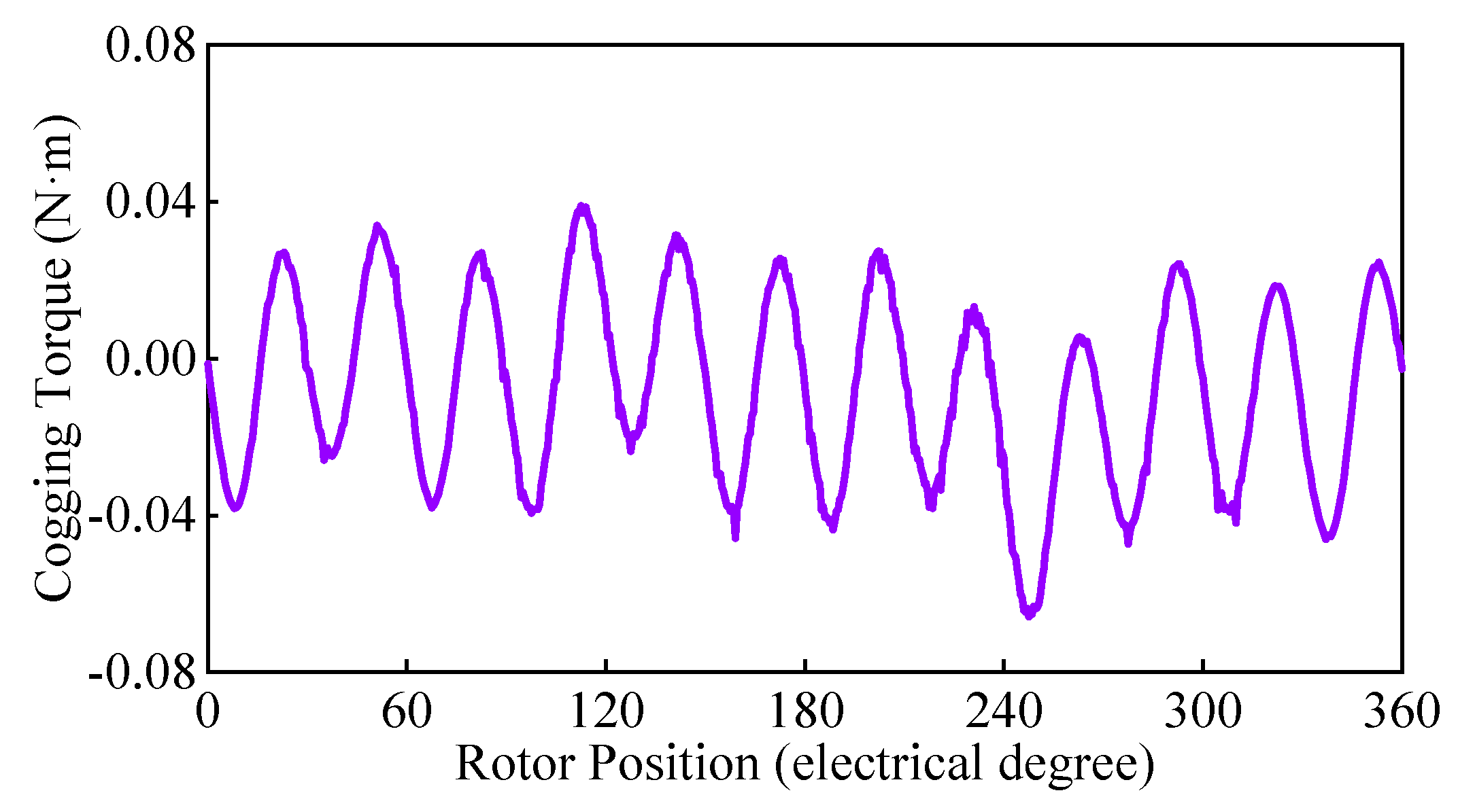
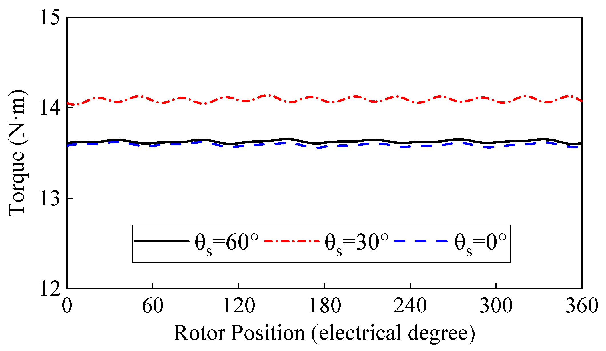
3.3. Cogging Torque and Electromagnetic Torque
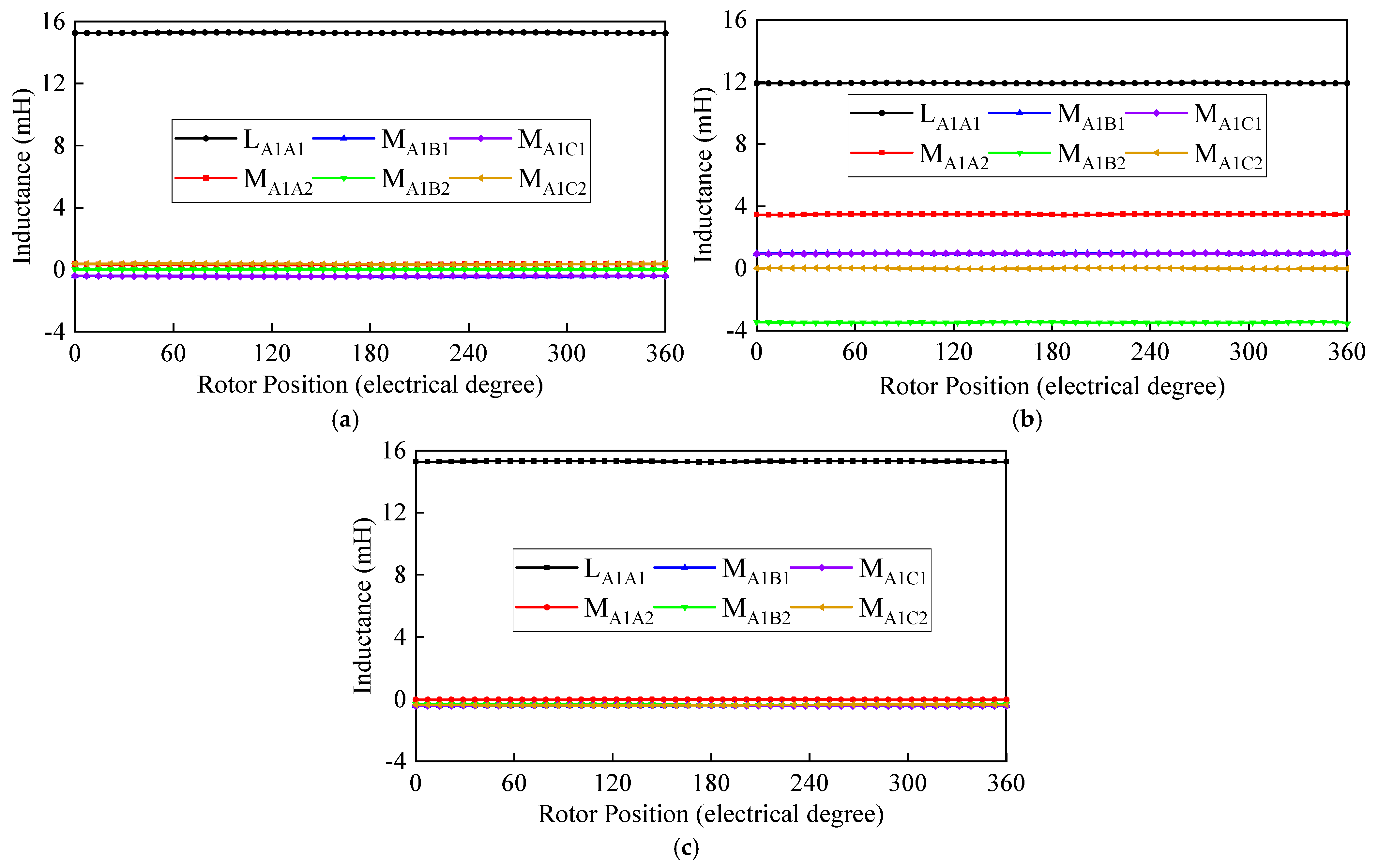
The cogging torque determines the starting performance of the permanent magnet generator, which is crucial to the low-speed OWC-WEC. Due to the same stator and rotor structure and size, the cogging torque waveform is shown in Figure 8. The cogging torque of the machine under the three winding configurations is the same. Its peak value is 0.068 Nm, which is relatively small compared to the other FSPM machines.
The electromagnetic torque waveform is analyzed as shown in Figure 9. When the armature current density with the peak of 2 A/mm2 is applied, it can be seen that the average electromagnetic torque is the same as the amplitude of the back EMF. The main torque ripple harmonics in the θs = 30° 12th, the main torque ripple harmonics in the θs = 60°, and θs = 0° is the sixth-order torque ripple. The average torque and torque ripple of the θs = 30° winding configuration are better than the other two configurations. This is more conducive to the improvement of the output capacity and stable operation of OWC-WEC.

3.4. Inductance

Figure 10 illustrates the inductance waveforms of the 24-slot/46-pole OR-FSPM generator with three winding configurations. It can be seen from Figure 7 and Table 3 that the self-inductance of the machine with the θs = 60° and θs = 0° winding configurations is large, and mutual inductance is small. That means the θs = 60° and θs = 0° winding configurations have better magnetic decoupling between phases. Thus, the 24-slot/46-pole OR-FSPM generator with the θs = 60° or θs = 0° winding configurations has better fault-tolerant capability.

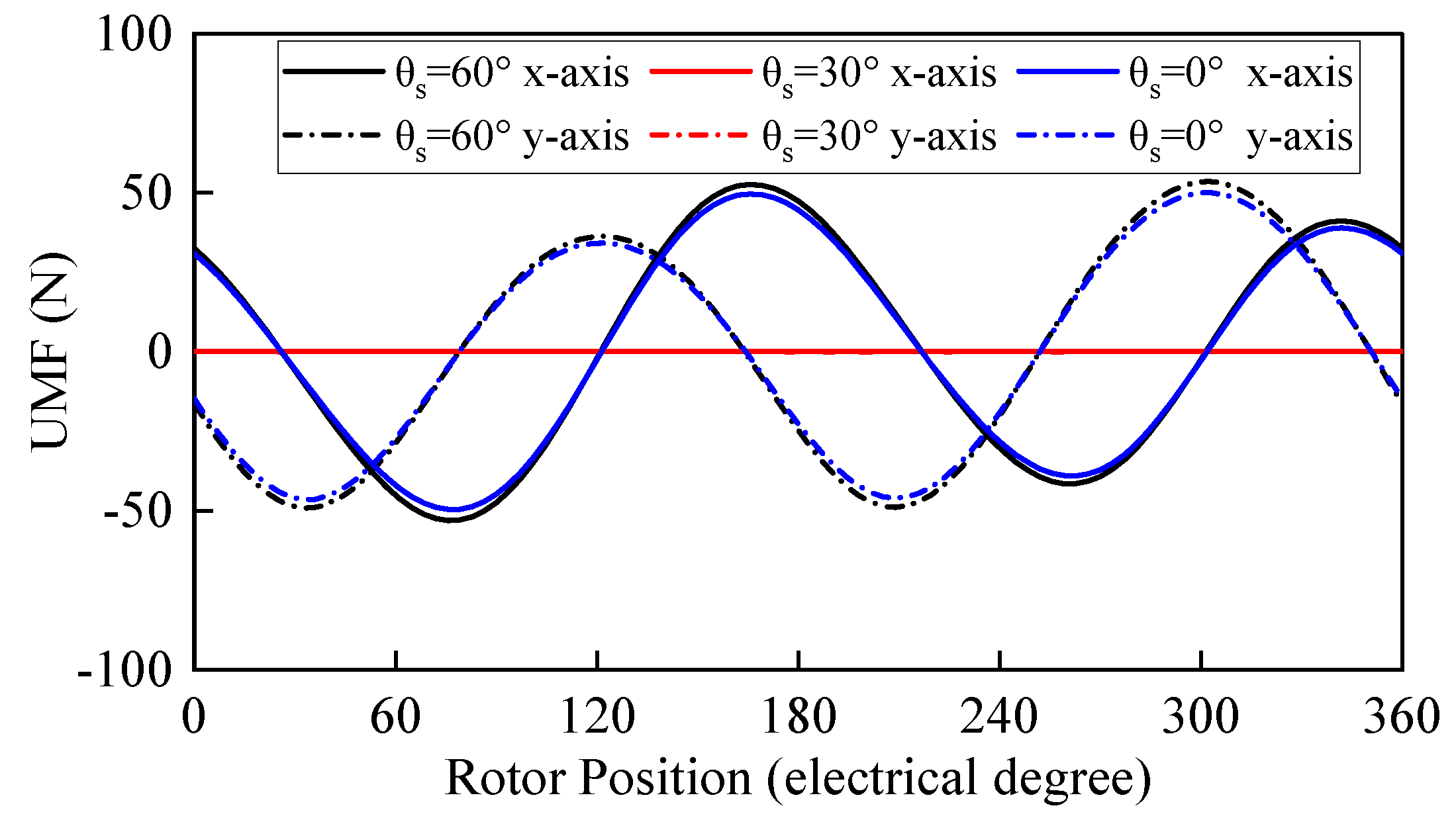
3.5. Unbalanced Magnetic Force

When one set of three-phase winding fault occurs, the dual three-phase motor can be operated independently by another set of three-phase winding. Therefore, when analyzing the dual three-phase machine, the operation of one set of three-phase winding should be considered at the same time. The UMF in the x-axis and y-axis of the three winding configurations is obtained by FEA when one set of three-phase winding is running, as demonstrated in Figure 11. The UMF will be produced when the θs = 60° and θs = 0° winding configurations are operated in one set of three-phase winding, while the UMF of θs = 30° is almost negligible.

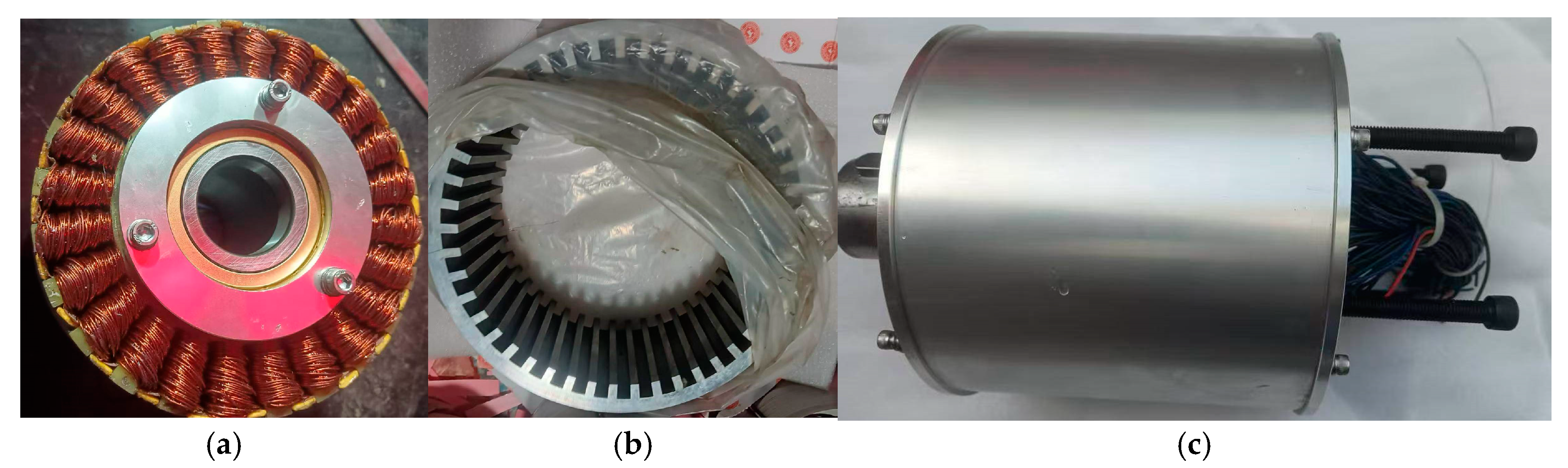
4. Experimental Verification

A 24-slot/46-pole OR-FSPM prototype has been constructed and tested. The prototype is displayed in Figure 12. The dragging system includes the prime machine, torque sensor and prototype. The open-circuit phase back EMF and rectified voltage waveforms of the prototype under the speed of 200 r/min are tested, as shown in Figure 13, with specific values listed in Table 4. The maximum error between the measured values of voltage and the FE-predicted values is less than 15%. The errors can be attributed to end effects and manufacturing defects. The more detailed research results will be presented in the future.

5. Conclusions

In this article, the application of a novel 24-slot/46-pole dual three-phase OR-FSPM generator with three winding configurations to OWC-WEC is proposed for the first time. The electromagnetic performance of the generator under three different phase-shift angle dual three-phase winding configurations is comparatively studied. The radial air-gap flux density and cogging torque of the three winding configurations are the same because they have the same stator/rotor structure. In contrast, although the fault tolerance of the θs = 60° winding configuration machine is poor, there is no UMF in a single three-phase winding operation, and it has higher amplitude of back EMF, larger electromagnetic torque and lower torque ripple. Finally, a prototype of the dual three-phase OR-FSPM machine is manufactured and measured. The tested results verify the analytical results well. The proposed 24-slot/46-pole OR-FSPM machine with the 30° PH-Angle winding configuration is a better choice for OWC-WEC.
In the future, we will continue to optimize the structure of the novel 24-slot/46-pole dual three-phase OR-FSPM generator and design a feasible structure that can be integrated with the air turbine to facilitate the verification of the operating performance of the new motor under real sea conditions so as to promote its large-scale application in OWC-WEC.

Author Contributions

M.H. conceived and designed this study; A.P. and L.Z. have given suggestions and revised the manuscript. All authors have read and agreed to the published version of the manuscript.

Funding

National Natural Science Foundation of China (U20A20106), National Marine Renewable Energy Fund Project of China (GHME2018SF02).

Data Availability Statement

Data is contained within the article.

Conflicts of Interest

The authors declare no conflicts of interest.

References

  1. Rauch, S.E.; Johnson, L.J. Design Principles of Flux-Switching Alternators; IEEE: Piscataway, NJ, USA, 1955. [Google Scholar]
  2. Rauch, S.E.; Johnson, L.J. Design Principles of Flux-Switch Alternators. Trans. Am. Inst. Electr. Eng. Part III Power Appar. Syst. 1955, 74, 1261–1268. [Google Scholar] [CrossRef]
  3. Sanabria-Walter, C. Design of a 600kW Ring-Type Direct-Drive Flux-Switching Permanent Magnet Machine for Aerospace Main Propulsion. In Proceedings of the 2014 16th European Conference on Power Electronics and Applications, Lappeenranta, Finland, 26–28 August 2014; pp. 1–10. [Google Scholar]
  4. Hao, L.; Lin, M.; Zhao, X.; Fu, X.; Zhu, Z.Q.; Jin, P. Static Characteristics Analysis and Experimental Study of a Novel Axial Field Flux-Switching Permanent Magnet Generator. IEEE Trans. Magn. 2012, 48, 4212–4215. [Google Scholar] [CrossRef]
  5. Hua, W.; Zhang, G.; Cheng, M. Investigation and Design of a High-Power Flux-Switching Permanent Magnet Machine for Hybrid Electric Vehicles. IEEE Trans. Magn. 2015, 51, 8201805. [Google Scholar] [CrossRef]
  6. Cao, R.; Jin, Y.; Zhang, Z.; Cheng, M. A New Double-Sided Linear Flux-Switching Permanent Magnet Motor With Yokeless Mover for Electromagnetic Launch System. IEEE Trans. Energy Convers. 2019, 34, 680–690. [Google Scholar] [CrossRef]
  7. Huang, L.; Hu, M.; Liu, J.; Yu, H.; Zeng, C.; Chen, Z. Electromagnetic Design of a 10-kW-Class Flux-Switching Linear Superconducting Hybrid Excitation Generator for Wave Energy Conversion. IEEE Trans. Appl. Supercond. 2017, 27, 5201706. [Google Scholar] [CrossRef]
  8. Khatri, P.; Liu, Z.; Rudolph, J.; Wang, X. A Study of a Modified Design of Dumbbell-Shaped Flux Switching Tubular Linear Generator for Regular Wave Energy Conversion. Renew. Energy 2023, 208, 287–300. [Google Scholar] [CrossRef]
  9. Liu, Z.; McGregor, C.; Ding, S.; Wang, X. Study of a Three-Dimensional Model Simulation of a Speed Amplified Flux Switching Linear Generator for Wave Energy Conversion and Its Design Optimization in the Ocean Environment. Energy 2023, 284, 128625. [Google Scholar] [CrossRef]
  10. Sheng, W. Wave Energy Conversion and Hydrodynamics Modelling Technologies: A Review. Renew. Sustain. Energy Rev. 2019, 109, 482–498. [Google Scholar] [CrossRef]
  11. Delmonte, N.; Barater, D.; Giuliani, F.; Cova, P.; Buticchi, G. Review of Oscillating Water Column Converters. IEEE Trans. Ind. Appl. 2016, 52, 1698–1710. [Google Scholar] [CrossRef]
  12. M’zoughi, F.; Bouallègue, S.; Garrido, A.J.; Garrido, I.; Ayadi, M. Stalling-Free Control Strategies for Oscillating-Water-Column-Based Wave Power Generation Plants. IEEE Trans. Energy Convers. 2018, 33, 209–222. [Google Scholar] [CrossRef]
  13. Thomas, A.S.; Zhu, Z.Q.; Owen, R.L.; Jewell, G.W.; Howe, D. Multiphase Flux-Switching Permanent-Magnet Brushless Machine for Aerospace Application. IEEE Trans. Ind. Appl. 2009, 45, 1971–1981. [Google Scholar] [CrossRef]
  14. Li, F.; Hua, W.; Tong, M.; Zhao, G.; Cheng, M. Nine-Phase Flux-Switching Permanent Magnet Brushless Machine for Low-Speed and High-Torque Applications. IEEE Trans. Magn. 2015, 51, 8700204. [Google Scholar] [CrossRef]
  15. Shao, L.; Hua, W.; Zhu, Z.Q.; Tong, M.; Zhao, G.; Yin, F.; Wu, Z.; Cheng, M. Influence of Rotor-Pole Number on Electromagnetic Performance in 12-Phase Redundant Switched Flux Permanent Magnet Machines for Wind Power Generation. IEEE Trans. Ind. Appl. 2017, 53, 3305–3316. [Google Scholar] [CrossRef]
  16. Zhao, J.; Lu, Z.; Han, Q.; Wang, L.; Wang, L. Design and Analysis of a Novel Six-Phase Axial Switched-Flux Permanent Magnet Machine With Different Winding Configuration. IEEE Trans. Magn. 2023, 59, 8102306. [Google Scholar] [CrossRef]
  17. Fei, W.; Luk, P.C.K.; Shen, J.X.; Wang, Y.; Jin, M. A Novel Permanent-Magnet Flux Switching Machine With an Outer-Rotor Configuration for In-Wheel Light Traction Applications. IEEE Trans. Ind. Appl. 2012, 48, 1496–1506. [Google Scholar] [CrossRef]
  18. Hua, W.; Zhang, H.; Cheng, M.; Meng, J.; Hou, C. An Outer-Rotor Flux-Switching Permanent-Magnet-Machine with Wedge-Shaped Magnets for in-Wheel Light Traction. IEEE Trans. Ind. Electron. 2017, 64, 69–80. [Google Scholar] [CrossRef]
  19. Zhang, H.; Hua, W.; Zhang, G. Analysis of Back-EMF Waveform of a Novel Outer-Rotor-Permanent-Magnet Flux-Switching Machine. IEEE Trans. Magn. 2017, 53, 8105004. [Google Scholar] [CrossRef]
  20. Mo, L.; Zhang, T.; Lu, Q. Design and Analysis of an Outer-Rotor-Permanent-Magnet Flux-Switching Machine for Electric Vehicle Applications. IEEE Trans. Appl. Supercond. 2019, 29, 3601305. [Google Scholar] [CrossRef]
  21. Farahzadi, M.; Ali, S.; Mirnikjoo, S.; Abbaszadeh, K.; Marignetti, F.; Salehi, M. Design and Experimental Validation of a New Outer Rotor Double PM Excited Flux Switching Generator for Direct Drive Wind Turbines. IEEE Access 2024, 12, 62256–62267. [Google Scholar] [CrossRef]
  22. Chen, H.; Liu, X.; EL-Refaie, A.M.; Zhao, J.; Demerdash, N.A.O.; He, J. Comparative Study of Winding Configurations of a Five-Phase Flux-Switching PM Machine. IEEE Trans. Energy Convers. 2019, 34, 1792–1804. [Google Scholar] [CrossRef]
  23. Chen, H.; Liu, X.; Demerdash, N.A.O.; EL-Refaie, A.M.; Zhao, J.; He, J. Comparison and Design Optimization of a Five-Phase Flux-Switching PM Machine for In-Wheel Traction Applications. IEEE Trans. Energy Convers. 2019, 34, 1805–1817. [Google Scholar] [CrossRef]
  24. Shao, L.; Hua, W.; Zhu, Z.Q.; Huang, W.; Wu, Z.; Li, F.; Cheng, M. Investigation on Phase Shift Between Multiple Multiphase Windings in Flux-Switching Permanent Magnet Machines. IEEE Trans. Ind. Appl. 2017, 53, 1958–1970. [Google Scholar] [CrossRef]
  25. Chen, J.T.; Zhu, Z.Q. Winding Configurations and Optimal Stator and Rotor Pole Combination of Flux-Switching PM Brushless AC Machines. IEEE Trans. Energy Convers. 2010, 25, 293–302. [Google Scholar] [CrossRef]
  26. Wu, Z.Z.; Zhu, Z.Q. Analysis of Air-Gap Field Modulation and Magnetic Gearing Effects in Switched Flux Permanent Magnet Machines. IEEE Trans. Magn. 2015, 51, 8105012. [Google Scholar] [CrossRef]
  27. Zhang, H.; Hua, W.; Wu, Z.; Zhu, X. Design Considerations of Novel Modular-Spoke-Type Permanent Magnet Machines. IEEE Trans. Ind. Appl. 2018, 54, 4236–4245. [Google Scholar] [CrossRef]
Figure 1. Topology of 24-slot/46-pole OR-FPSM generator.
Energies 18 01021 g001
Figure 2. Coil EMF and phase EMF phasors. (a) θs = 60°. (b) θs = 30°. (c) θs = 0°.
Energies 18 01021 g002
Figure 3. Open −circuit PM field distribution. (a) Flux line. (b) Flux density.
Energies 18 01021 g003
Figure 4. Open −circuit air-gap radial flux density. (a) Waveform. (b) Spectra.
Energies 18 01021 g004
Figure 5. PM flux linkage. (a) θs = 60°. (b) θs = 30°. (c) θs = 0°.
Energies 18 01021 g005
Figure 6. Phase back EMF. (a) A1 −phase waveform. (b) Spectra.
Energies 18 01021 g006
Figure 7. Rectified voltage. (a) Waveform. (b) Spectra.
Energies 18 01021 g007
Figure 8. Cogging torque.
Energies 18 01021 g008
Figure 9. Electromagnetic torque.
Energies 18 01021 g009
Figure 10. Inductance. (a) θs = 60°. (b) θs = 30°. (c) θs = 0°.
Energies 18 01021 g010
Figure 11. Comparison of unbalanced magnetic force of a single set of three −phase winding during operation.
Energies 18 01021 g011
Figure 12. Prototyped 24-slot/46-pole OR-FSPM machine. (a) Stator. (b) Rotor. (c) Assembled prototype.
Energies 18 01021 g012
Figure 13. Tested voltage waveforms of the dual three −phase OR-FSPM machine. (a) Phase back −EMF. (b) Rectified voltage.
Energies 18 01021 g013
Table 1. Main structure parameters of 24-slot/46-pole OR-FSPM generator.
ParametersUnitValue
Rotor Outer Diametermm206.5
Air Gap Lengthmm0.75
Stator Outer Diametermm170
Stator Inner Diametermm102
Stack Lengthmm100
Rotor Pole Arcdegree3
Rotor Pole Lengthmm8.5
Stator Pole Arcdegree2.75
Stator Slot Arcdegree7.5
Inner Iron Bridge Thicknessmm2
Outer Iron Bridge Thicknessmm0.5
PM Lengthmm34
PM Arcdegree2
Number of Turns per Coil-55
PM Material-N40SH
Lamination Type-20W1500
Table 2. Winding coefficients of three winding configurations.
Itemθs = 60°θs = 30°θs = 0°
kd0.96610.966
kp0.9660.9660.966
kω0.9330.9660.933
Table 3. Average value of inductance.
Inductance (mH)
θs = 60°
Inductance (mH)
θs = 30°
Inductance (mH)
θs = 0°
LA1A115.2811.9315.31
MA1B1−0.410.96−0.41
MA1C1−0.410.96−0.41
MA1A20.393.48−0.02
MA1B20.02−3.48−0.34
MA1C20.370−0.37
Table 4. Tested and FEA voltage.
PH-AngleMethodAmplitude of Phase
Back-EMF (V)
Average Rectified Voltage (V)
θs = 60°Measured31.562.9
FEA36.770.1
θs = 30°Measured33.562.4
FEA37.569.2
θs = 0°Measured3255.6
FEA36.760.1
Disclaimer/Publisher’s Note: The statements, opinions and data contained in all publications are solely those of the individual author(s) and contributor(s) and not of MDPI and/or the editor(s). MDPI and/or the editor(s) disclaim responsibility for any injury to people or property resulting from any ideas, methods, instructions or products referred to in the content.

