1. Introduction
The transportation sector is a major contributor to global CO
2 emissions, with aviation accounting for approximately 3% of the total. Following a 20% reduction from 2019 to 2022 due to COVID-19 pandemic effects, emissions from this sector are expected to exceed 2019 levels by 2025, according to [
1]. Addressing this issue necessitates the exploration of alternative and cleaner aircraft propulsion technologies to achieve the European Green Deal’s carbon neutrality target.
Against this background, the European Union’s Clean Aviation program is advancing on two research streams, including the optimization of thermal engines for short-to-medium-range commercial aircraft exploiting sustainable aviation fuels, as well as the hybridization of regional aircraft via hydrogen and fuel cells [
2]. The latter option is also being thoroughly investigated by the automotive [
3] and heavy-duty vehicle industries [
4,
5] in order to leverage the high efficiency of fuel cells in converting chemical energy from reactants into electricity. It is important to underscore that, to fully exploit the intrinsic advantage of fuel cells in generating power without emissions, they should be fueled with green hydrogen. The latter, which is producible via water electrolysis, requires innovative airport infrastructures to produce hydrogen on-site through renewable energy sources (i.e., solar and wind energy). This process not only facilitates a deep decarbonization of the sector but also contributes to mitigating the intermittency issues associated with renewables [
6].
In the effort to achieve greener aircraft propulsion, proton exchange membrane (PEM) fuel cell, when suitably integrated with energy storage systems such as batteries, emerges as the most feasible solution [
7], thanks to its rapid dynamics and power-to-weight ratio approaching the 2 kW/kg target at system level, as highlighted by the Strategic Research and Innovation Agenda of the Clean Hydrogen Partnership (CH2E-SRIA) [
8]. Hence, although solid oxide fuel cells (SOFCs) are also being studied for aviation purposes, either for propulsion [
9,
10] or as auxiliary power units [
11], PEM technology has been chosen for several research and demonstration projects focused on hybridized aircraft. The project in [
12] aims to develop a high-power density PEM fuel cell system (PEMFCS) to propel a 2–4 seat hydrogen aircraft, whereas a 500 kW PEMFCS is considered by the researchers of [
13] for retrofitting regional aircraft. Additionally, the project in [
14] also includes the development of a fully electric concept that utilizes electric propeller propulsion systems powered by hydrogen fuel cells. However, it should be noted that for aeronautical purposes, PEM technology suffers from tricky thermal management as a result of low-temperature heat rejection. This results in a cumbersome thermal management system, which can adversely impact aerodynamic drag. For this reason, researchers are currently investigating novel cooling options (e.g., phase change-heat pump cooling strategies) as an alternative to the well-established liquid cooling approaches to reduce the net cruise power while optimizing the optimal current density of PEM fuel cell technology, as demonstrated in [
15].
Against this background, the HECATE (Hybrid ElectriC regional Aircraft distribution Technologies) project addresses key challenges related to the adoption of hybrid electric powertrains for regional aircraft, such as high voltage and optimized thermal management, while employing digital twin for system design optimization [
16].
For a regional aircraft, a series-parallel powertrain configuration is well suited to address the hybridization challenge [
17]. In this setup, the turboprop engine is connected through a gearbox with the electric motor, which is powered by the series hybrid configuration resulting from the PEMFCS and battery pack integration. The combined use of such electrochemical devices is justified by factors such as the superior energy density of the PEM systems and the ability to deliver continuous power as long as hydrogen is available, thereby alleviating range anxiety typical of battery-powered systems [
18]. Conversely, the battery acts as a buffer during highly fluctuating power demand phases so as to prevent excessive fuel cell stack degradation. In this regard, it must be stressed that degradation and the resulting limited durability of fuel cells represent significant challenges for their deep commercialization. The identification of reliable health indicators via prognostic and health management techniques can effectively help to extend the lifetime of these devices by detecting their aging status [
19]. Furthermore, knowing the health status of fuel cells can enable degradation-aware sizing of the hybrid unit for ensuring a certain number of flight hours while maintaining the aircraft’s maximum take-off mass within acceptable limits. As for the latter aspect, based on the current technological scenario, research [
20] has demonstrated that an all-electric aircraft utilizing PEM fuel cells would lead to a 25–50% mass increase compared to a conventional kerosene-powered one. Therefore, hybrid units and their effective energy management play a significant role, as proper power allocation between the hybridizing components leads to downsized devices while mitigating aging concerns and minimizing hydrogen consumption.
1.1. Research Background
Extensive research has been conducted on energy management strategies for aeronautical PEMFC-battery hybrid systems, as well as on modeling methodologies used to assess fuel cell stacks’ electrical variables, thus ensuring effective integration with the direct current (DC) bus line. More specifically, the goal of this section is to provide an overview of the most widely used approaches for addressing fuel cell system degradation through appropriately defined control actions. Additionally, the section aims at illustrating existing electrochemical models for calculating voltage and current at the stack level.
As for the latter aspect, it is notable that scholars of [
21] carried out a comprehensive literature investigation that distinguishes between quasi-static and dynamic models to properly estimate fuel cell voltage. It emerges that the former are commonly used to fine-tune hybrid unit’s control strategies. Specifically, detailed equivalent resistors-based and parametric models, recognized as quasi-static approaches, are typically employed to derive the quasi-stationary polarization curve of fuel cells by calculating activation, ohmic, and concentration overpotentials. However, the key distinction between resistors and parametric models lies in the fact that geometrical features, such as the electrochemical active area, are not considered in parametric modeling. Instead, various coefficients are treated as tunable parameters, even though they depend on the fuel cell’s operating conditions. The number of parameters in parametric approaches can vary from five (i.e., Chamberlin–Kim’s model) to seven (i.e., Amphlett and Larminie-Dick’s model) [
21]. On the other hand, as well as quasi-static approaches, dynamic models still consider a tunable set of parameters but allow for capturing the double-layer effect that accounts for the different polarity at the interface between the cathode and the membrane. This effect is commonly modeled by introducing an equivalent capacitor, and the resulting time constant is a function of activation and concentration resistances.
It is notable that a common issue to be accounted for when applying quasi-static and also dynamic models relates to suitably accounting for maldistribution effects [
22]. Particularly, a dedicated and burdensome experimental campaign shall be carried out to fully account for the impact of air uneven distribution across the stack to avoid excessive discrepancies between each cell voltage, which in turn would require accounting for the different stoichiometric ratios when estimating the voltage as a function of the polarization curve model inputs, as extensively discussed in the contribution of Huang et al. [
22].
The authors of [
23] conducted a multi-objective optimization to co-design energy management and sizing parameters of a fully electrified regional aircraft that exploits the coupling between fuel cell and battery. The proposed integrated approach minimizes hydrogen consumption and the cost of fuel cell degradation by varying the degree of hybridization, whereas a real-time power distribution algorithm is embedded in the procedure. Nevertheless, the approach for assessing the voltage at the single-cell level is not deepened in the work.
A control strategy for the electrification of regional aircraft has been proposed in [
24], where a high-temperature PEMFCS is coupled to a battery, which solely serves as a support during the take-off stage. The analysis also highlights the potential of oversizing the fuel cell stack to enhance operational efficiency, which, in turn, leads to reducing the mass of the thermal management system.
Two rule-based control strategies are proposed in [
25], each with distinct objectives. The first aims to balance the battery state of charge (SOC) with the available hydrogen to ensure continuous power supply and prevent shortages of one device, while the other, based on state-machine logic, focuses on extending the device’s lifetime by keeping stack voltage and SOC variation within safe ranges. Therefore, in the second control scheme, the fuel cell system operates at fixed power levels, which are decided based upon the actual SOC and load demand. Furthermore, the fuel cell stack is modeled as a controlled voltage source in series with a resistor, thus neglecting activation and concentration losses. It is notable that rule-based, state machine, and fuzzy-logic control algorithms are frequently utilized in fuel cell-based unmanned aerial vehicle (UAV) applications, where hybrid configurations are considered the most suitable for propulsion purposes [
26]. As outlined by [
26], the coupling between fuel cells and batteries leads to increased endurance due to higher energy and power densities compared to systems relying on a single source. An in-depth classification of existing energy management strategies for UAVs is provided by [
27], which distinguishes between rule-based, optimization, and machine learning techniques, thus profiling a set of approaches also deployable for larger aircraft applications.
Despite the increased computational burden and the challenges in real-time implementation, optimal (e.g., dynamic programming or Pontryagin’s minimum principle) or sub-optimal control policies (e.g., equivalent consumption minimization strategy (ECMS)) are also used in aviation [
27]. For example, ref. [
28] addresses the power distribution for fully electrified aircraft using a degradation-conscious ECMS and sequential quadratic programming, whose performance is compared with state machine-based and daisy-chain allocation algorithms. Based on semi-empirical degradation models, both hydrogen consumption and hybrid unit’s deterioration costs are minimized, while optimizing power distribution by relying on a multi-stack fuel cell system. Moreover, a semi-empirical parametric model allows for estimating fuel cell stack voltage. The same electrochemical model is also implemented in [
29], which applies filters on battery power supply and SOC to assess the power distribution of hybrid systems by deploying a method inspired by Bellman’s principle of optimality. In the framework of optimization-based approaches, dynamic programming has been employed in [
30] to optimize power sharing between the fuel cell system and battery, aiming at minimizing operating and degradation costs. Particularly, limitations on the fuel cell system’s power slope and allowable power levels are taken into account, alongside a comparison of various aircraft topologies. The latter are distinguished by the presence of a DC/DC converter on the battery (i.e., battery-active), the PEMFCS (i.e., fuel cell-active), or both (i.e., fully active). However, a model that systematically estimates voltage and auxiliary power absorption is not clearly illustrated. Dynamic programming is also deployed by the authors of [
31] for the energy management of a battery and fuel cell-powered UAV. The performance of the control policy was assessed against state-machine and rule-based control strategies while exploiting a semi-empirical model to obtain the fuel cell polarization curve with a number of coefficients assumed from the literature.
Therefore, from the analysis of the contributions cited above, it can be deduced that, in aviation hybrid units, energy management and degradation are treated as a coupled problem. Yet, although many works focus on quantifying degradation, being inspired by established knowledge in the automotive industry [
32], the implementation of degradation-aware strategies, which limit the occurrence of high-power and low-power conditions, is also a viable avenue, as discussed in [
33,
34].
On the other hand, other works, such as [
35], move their focus on all-electric aircraft solely powered by the PEMFCS. Particularly, the authors carried out a sizing procedure, which exploits the model in [
36] to find the analytical solution for the polarization curve under the large overpotential assumptions. Although the model is valuable and potentially integrable within multi-level simulation frameworks, it relies on several parameters sourced from the literature and requires the tuning of other parameters, such as gas diffusion layer thickness and ohmic resistance, to accurately reproduce the fuel cell’s behavior.
In addition, it is worth highlighting that polynomial fitting techniques can be employed not only to assess hydrogen consumption, as shown in [
30,
37], but also to relate PEMFCS efficiency and stack voltage to fuel cell power and current, respectively, as demonstrated in [
38]. Similar approaches are also utilized in [
39,
40], albeit focused on road vehicles.
Specifically, ref. [
39] uses available experimental data from [
41] to model both the PEMFCS and DC/DC converter efficiency as a function of the hydrogen-based device’s delivered net power. Nonetheless, the PEMFCS efficiency is solely used to evaluate hydrogen consumption, while the converter efficiency permits us to determine the stack’s operating current, assuming the bus voltage corresponds to that of the battery. Still utilizing the database in [
41], a fitting procedure is performed in [
40] to link auxiliaries’ power consumption to the stack’s power through a quadratic relationship.
Notably, the current literature lacks a computationally efficient grey-box model suitable for integration into aeronautical simulation frameworks, which systematically links the fuel cell stack’s voltage and current to the net power delivered while also estimating parasitic absorption and cooling system load based on a flexible degradation-aware power distribution. Since designing aircraft requires an iterative procedure consisting of multiple steps, leveraging this kind of approach can effectively contribute to easily meeting the aircraft’s top-level requirements in terms of voltage and current imposed on the DC line at the initial design stage. Additionally, it should be also noted that, owing to the complexity and computational burden resulting from simulating the electrical architecture, aircraft manufacturers require simplified models that can help in achieving reliable preliminary results. Furthermore, polarization-based models face limitations in terms of scalability, necessitating parameters recalibration when considering stacks produced by different manufacturers. This approach is not particularly advantageous during the preliminary phases of aircraft design, where large-scale scenario analyses are often necessary.
1.2. Key Contributions and Paper Organization
This article examines the hybrid unit of a turboprop-based regional aircraft, which comprises a PEMFCS and lithium-ion battery. For this architecture, sized according to authors’ previous work [
42], a flexible degradation-aware energy management strategy is presented to assess the power delivery of individual components depending on specific flight stages. Once the health-conscious power distribution is determined, the PEMFCS power supply is fed as input into an electrical variable’s estimator, the efficiency-driven model, to ultimately estimate the fuel cell stack’s electrical variables. It is worth pointing out here that, hereinafter, the design task is addressed, aiming at integrating the PEMFCS with the onboard electrical distribution. To support the latter scope, it is required to include the proposed efficiency-driven model to quickly and accurately estimate the variations in the order of magnitudes of stack voltage and current as a function of the currently investigated configuration. The latter aspect (i.e., providing the mathematical tool with electrical variable simulation capabilities) represents significant methodological progress with respect to the mentioned previous contribution [
42].
The main contributions of the paper can be summarized as follows:
The proposed efficiency-driven model estimates PEM fuel cell stack (PEMFC) electrical variables by relying solely on two mathematical relationships. Particularly, the PEMFC voltage is linked to stack efficiency, while the current is related to the PEMFCS efficiency. The efficiency curves are employed in a normalized form as a function of the PEMFCS net power output decided by the energy management strategy. While the equations included in such a grey-box approach are well established in the thermodynamic analysis of fuel cell systems, the key contribution of this study lies in inverting them, thus providing a scalable and user-friendly methodology seamlessly integrable within an aircraft’s electrical architecture. This way, various degrees of hybridization for the hybrid unit can be easily explored to identify the configuration that is most suitable to guarantee a compromise between voltage requirements before the DC/DC converter and overall added mass and volume, i.e., due to the addition of both the PEMFCS and battery pack. Additionally, the performance of stacks produced by different manufacturers can be compared without the need for fine-tuning the numerous parameters required by quasi-static polarization models but merely by changing the efficiency curves. To the best of the authors’ knowledge, a similar approach is not yet available in the literature. It is also worth pointing out how some PEMFCS exhibit different stack efficiency curve profiles, as pointed out in a recent and massively referenced report [
41] presenting the likely richest and most informative voltage and efficiency curves database at the current stage. The aforementioned stack efficiency curve may exhibit non-monotonic behavior, which may not be entirely captured through the application of traditional polarization modeling approaches. However, it is also worth mentioning that compared to dynamic models, the efficiency-driven model does not consider the double-layer effect.
The parasitic power consumed by the ancillaries included in the balance of plant is typically calculated by relying only on the compressor’s absorption while neglecting or assuming constant other contributions, for example, that of the recirculation pump [
21]. In this work, the outcomes of the efficiency-driven model are exploited to solve a power balance on the DC line for globally estimating these kinds of losses.
Although PEMs offer advantages in terms of limited gravimetric and volumetric impact, the main issue related to their use in aviation is troublesome thermal management. This brings the need to estimate both the heat generated at the stack level and the cooling system load. To the best of the authors’ knowledge, this paper represents the first attempt to calculate such variables for aviation applications.
To promote a more distributed propulsion that is beneficial towards improved reliability, redundancy, and space flexibility, a second-level design is presented that determines the number of stacks to be operated in parallel and the number of cells included in each stack as a function of both the voltage constraints upstream of the DC/DC converter and the selected PEMFCS power rating. This is made possible by means of the scalability and flexibility of the proposed efficiency-driven model, as well as due to the adoption of a specification-independent power-split strategy governing the PEMFCS-battery interaction, which allows to automatically adapt the control rules to the newly investigated hybrid unit configuration within comprehensive aeronautical integrated simulation frameworks.
The manuscript is organized as follows: In
Section 2, the hybrid unit configuration and design constraints are presented. Then, the mathematical tool, including the degradation-aware energy management strategy and efficiency-driven model, is introduced. In
Section 3, the methodology is applied to a realistic regional aircraft’s mission profile, while
Section 4 illustrates conclusions and future research directions.
2. Methodology
This section describes in detail the modeling and control approaches deployed hereinafter. The study presents a two-level structured mathematical tool designed to achieve dual objectives. Particularly, the proposed efficiency-driven model is employed to estimate the stack’s current (
) and voltage (
) for the selected hybrid unit, by also leveraging the outcomes of the control strategy alongside experimentally derived efficiency curves at both system and stack levels. Furthermore, by means of such an approach, the rate of heat generated by the stack (
), cooling system load (
), and balance-of-plant auxiliaries’ power absorption (
) are calculated. A schematic of the methodology is illustrated in
Figure 1a, which also presents the load profile to be satisfied at various altitudes.
The section is structured into three parts. First, the architecture of the hybrid unit is presented. Next, the modeling approach for the individual components energy management strategy adopted here for the battery-PEMFCS unit is described. Finally, the efficiency-driven model is illustrated.
2.1. Hybrid Unit Configuration
The powertrain configuration chosen for the analysis presented in this manuscript is a series-parallel arrangement, as shown in
Figure 1b. The hybrid powertrain series configuration integrates the battery and the PEMFCS, which together constitute the hybrid unit supplying power to the electric motor. The electric motor is mounted on the shaft of the turboprop engine and coupled to it through a gearbox, thereby establishing an overall parallel hybrid powertrain configuration. The primary advantage of this architecture lies in its flexibility, allowing both the hybrid unit and the thermal engine to contribute to propulsion either independently or concurrently. Additionally, it enables a reduction in the number of propellers and achieves a more compact design compared to a series hybrid configuration [
43].
In view of the flexibility in energy management provided by this architecture, an a priori-established load (
) is assigned to the hybrid unit for contributing to the propulsion. The availability of such a load profile allows for decoupling the electrical and thermal entities of the powertrain, thus enabling the focus to be placed here solely on the hybrid electric unit. It is important to highlight that the mission profile illustrated in
Figure 1a reflects the actual electrical power demand of an existing regional aircraft. Consequently, the remaining part of the load, particularly during the cruise phase, is fulfilled by the thermal engine (i.e., gas turbine).
Particularly, the energy management strategy determines the PEMFCS () and battery power supply () accounting for degradation-oriented adjustments. The PEMFCS is oversized to avoid high-power operation, while is constrained to an idling level, corresponding to the maximum efficiency point, aiming at minimizing degradation occurring during start-up and shut-down phases. Moreover, the PEMFCS dynamic limitations are also considered through a power rate limiter (RL), so as to eliminate issues associated with rapid transients.
For the sizing of the hybrid unit, the procedure described in [
42] is used, which assumes the electric motor power (
) and fuel cell system power rating (
) as the dimensioning parameters according to Equation (1). Therefore,
and
are a priori established, while
results from a power balance at the electrical node (see
Figure 1b) that account for an average motor efficiency set to 0.9. It is important to note that in the remaining part of the manuscript the electric motor is not considered, as the electric power demand is already provided as an input to the procedure.
It is worth specifying that the electrical module sizing procedure must comply with the following constraints on the overall added mass () and volume ().
kg;
m3.
Particularly,
results from the contributions of the hydrogen tank, hydrogen consumed, battery, and PEMFCS, while
accounts for the volumes of the tank, PEMFCS, and battery. To calculate
and
the technological assumptions presented in
Table 1 are utilized. Particularly, the selected PEMFCS gravimetric and volumetric power density relies on the data provided by [
8] for 2030, while tank gravimetric and volumetric capacity, which refer to liquid hydrogen storage, were retrieved from [
42].
It is noteworthy that the snowball effect is not considered in this analysis, thereby neglecting the increase in power demand resulting from the additional mass of the installed hybrid unit. This choice can be justified by the fact that the PEMFCS and battery shall satisfy a specific power demand that is built upon the earlier mentioned constraints on the overall added mass and volume. Moreover, it is also worth recalling that the main aim of this manuscript is the development of models and control strategies for PEMFCS-based hybrid units meeting the accuracy and computational burden of integrated simulation frameworks, thus being suitable to address the well-known aircraft design-related snowball effect.
2.2. Mathematical Models
This section outlines the modeling approach used to evaluate hydrogen consumption and battery SOC.
2.2.1. Hydrogen Consumption Estimation
The hydrogen consumption is estimated via Equation (2) based on the PEMFCS efficiency (
) general definition. The system-level efficiency is evaluated through a black-box model that relies on experimental data gathered at the University of Salerno test bench. Notably, an operating range has been investigated with the aim of accounting for the CH2E-SRIA efficiency target of meeting the power density requirements at 0.65 V, thus ensuring satisfactory stack efficiency values [
8]. For the examined stack, this target value is reached at 1 A/cm
2 current density.
In Equation (2),
is the higher heating value (i.e., 141,900 kJ/kg) of hydrogen. The PEMFCS efficiency curve is presented in a normalized form in
Section 2.4, owing to its crucial role in the implementation of the efficiency-driven model.
2.2.2. Battery Model
Integrating an energy storage device with the PEMFCS in a hybrid aircraft architecture offers several advantages, as it addresses the low power density and slow dynamics of hydrogen-fueled devices while fully exploiting their unique characteristics of high energy density, high efficiency, and increased endurance [
44]. The favorable trade-off between gravimetric energy and power density, combined with the scalability to achieve several kWh of installed capacity, makes lithium-ion technology the predominant choice in aviation applications [
45]. Therefore, the battery model illustrated in the green box of
Figure 1b refers to such a technology.
The model comprises an open circuit voltage (
) in series with an internal resistance (
) to evaluate the instantaneous SOC during discharging and charging phases, according to the design assumption outlined in [
42]. Particularly, in the latter study, multiple linear regressions were employed to evaluate the battery’s capacity and its gravimetric and volumetric impacts as a function of the gravimetric energy density at the cell level. Hence, based on
, resulting from the control strategy, the current flowing through the circuit (
) is calculated via Equation (3) and then used to estimate the SOC, as shown in Equation (4).
In Equation (3),
and
depends on the battery SOC according to the graphs illustrated in the green box of
Figure 1b, while in Equation (4),
is the battery capacity expressed in Coulombs and
represents the battery SOC at the beginning of the mission.
2.3. Control Strategy
The control strategy presented in this study suitably tailors previous authors’ results attained in the automotive field [
46,
47] to meet specific aviation requirements. Indeed, the flight mission depicted in
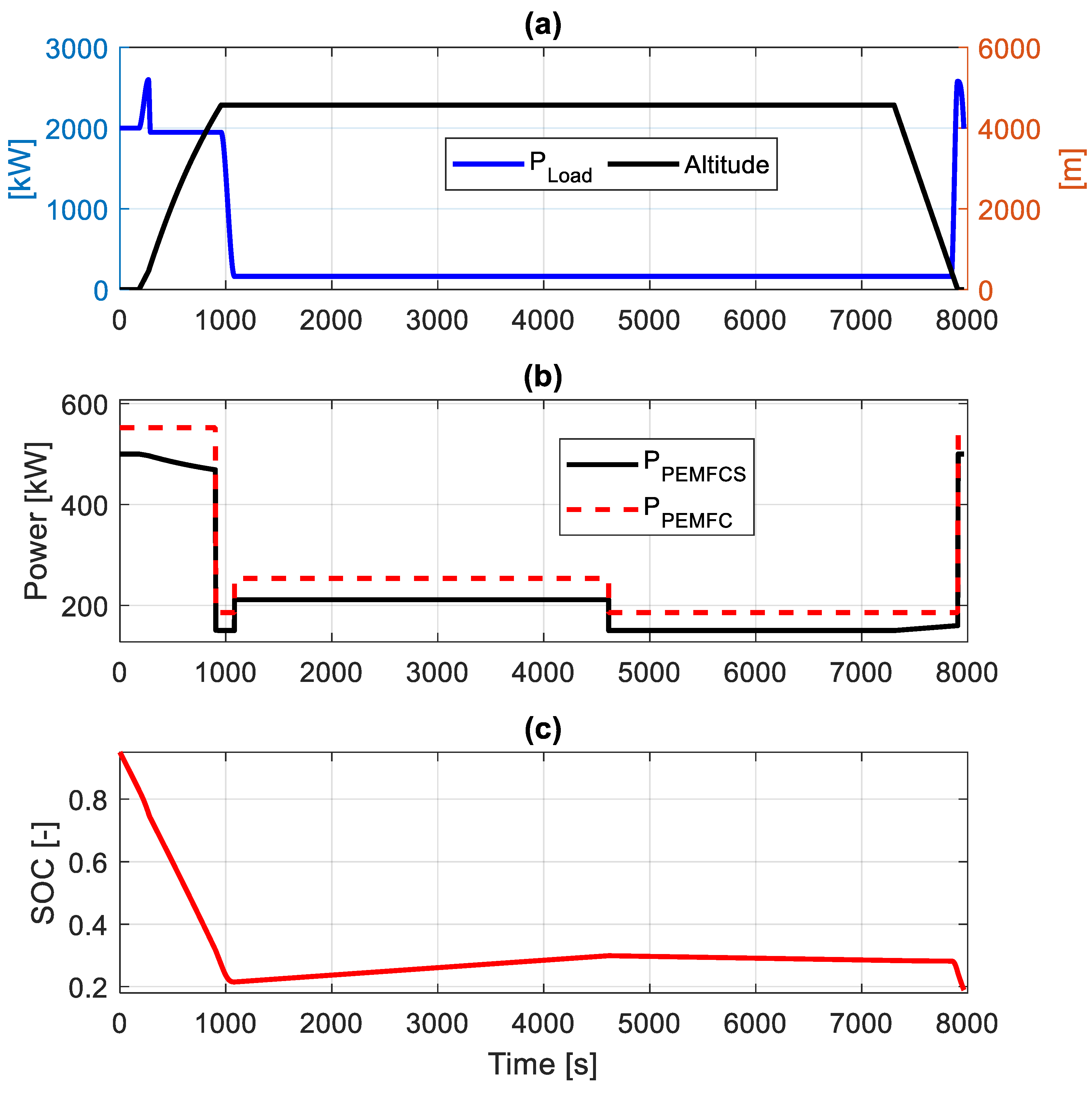
Figure 1a, representative of the realistic electrical load of a regional aircraft, outlines that high power, ranging from 2000 kW to 2600 kW, is requested during taxi-out, take-off, and climbing phases, which reduces down to 165 kW during cruising, where a maximum altitude of approximately 4600 m is achieved. A further increase in power up to 2600 kW occurs during landing and taxi-in.
Therefore, it is reasonable to employ an energy management strategy that allows the PEMFCS to operate at the maximum admitted power during the aforementioned high power phases, while implementing a thermostatic-like control throughout the remaining flight stages, so as to recharge the battery and keep its SOC within safe values. Hence, a threshold value for the mission power (
), here set to 1800 kW, is defined to guarantee proper implementation of such a blended rule-based control (BRBC) scheme. Regarding the thermostatic strategy, two control variables, battery SOC admitted variation (
) and
, are mapped depending on the average mission power demand (
, the latter determined via an a priori estimation of the future power request over a specified time horizon (TH) [
47], here set to 180 s. Particularly,
and
result from Equation (5), which minimizes hydrogen mass flow rate (
) in the TH while guaranteeing battery charge-sustaining management.
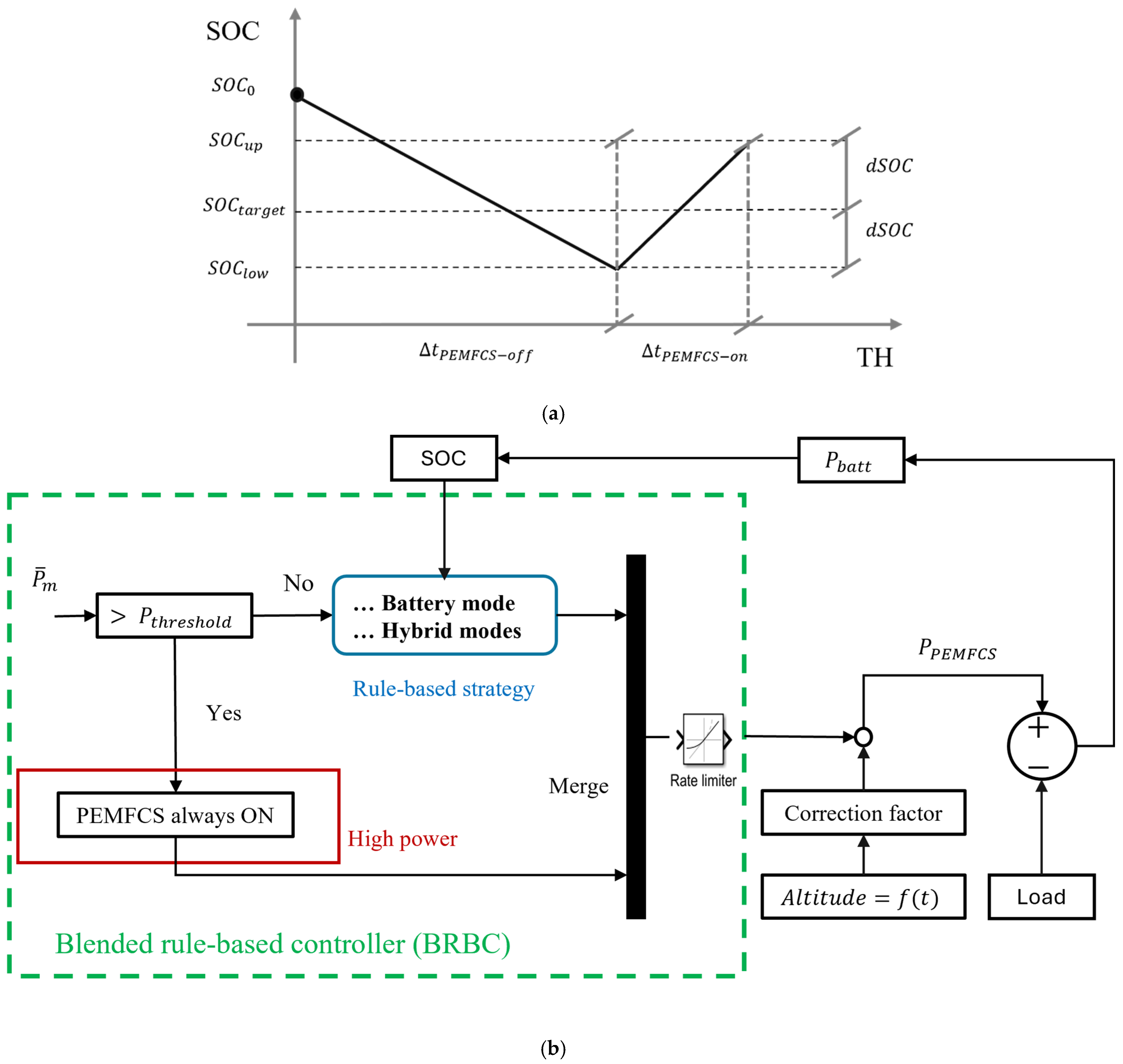
In the second expression of Equation (5),
denotes the window length within the TH during which the PEMFCS is kept off, allowing for battery discharging. As visible in
Figure 2a,
features the battery SOC reduction from
to that requiring the subsequent PEMFCS activation (i.e.,
). When activated, the PEMFCS operates at constant power to ensure that the battery SOC is restored to an upper SOC (i.e.,
). Therefore,
is the average value between
and
that oscillate around a target value (
) to be achieved at the end of the mission. Moreover, it is worth noting that these maps are obtained depending on a reference powertrain architecture featuring a given PEMFCS power rating and battery capacity. Such a reference arrangement is thus utilized to normalize the maps, while a denormalization process allows us to derive heuristic control rules, which can fruitfully be adapted to different powertrain configurations [
47], thus fulfilling an increasing demand in the hybrid vehicle control community [
48]. For the specific case study, the control maps were obtained considering a PEMFCS reference size of 900 kW and a battery capacity of 745 kWh.
Based on the synoptic diagram shown in
Figure 2b and mathematical models described in
Section 2.2, the following hybrid unit’s operating conditions can be recognized and implemented in Simulink
® by means of several ‘if-then’ rules:
High power mode: This mode is activated during high power phases (i.e., take-off and landing) when exceeds 1800 kW. The PEMFCS operates at maximum allowable power () to prevent substantial battery oversizing while avoiding its rapid discharge.
Battery mode: The control logics transitions into this operating mode when the battery SOC exceeds , calculated in Equation (6) as the sum of and , which is a function of . Consequently, the PEMFCS operates at idle (), corresponding to its best efficiency point, in order to reduce low-current operations and minimize hydrogen consumption.
where
, calculated in Equation (8), is the minimum SOC admitted by the energy management strategy.
However, two viable control options can be pursued, differentiated by at the previous time instant. Indeed, if the device was working in idling mode, it continues to operate in this condition since the battery does not need immediate recharging, as its SOC is within a safe range. On the other hand, if was higher than in the previous time step, the PEMFCS operates at the current time in accordance with the maps.
Hybrid mode 2: This condition is activated when the battery SOC drops below the lower threshold and the battery needs to be recharged. Subsequently, the PEMFCS operates at the power level determined by the denormalized control maps, which approaches the maximum, to both satisfy the load and recharge the battery.
The hybrid unit’s operating modes are then merged, and an RL Simulink® block influences the PEMFCS power supply, constraining its power slope to account for the device’s dynamics.
Finally, as for computation complexity, it is worth pointing out that the proposed control strategy features a run-time of approximately 8 s on a laptop mounting a 13th Gen Intel
(R) Core
TM i7-1360P CPU@2.20 GHz processor. This performance is compatible with real-time applications, as also discussed in [
46].
2.3.1. Performance Drop with Altitude
At fixed current density, while the gross power delivered by the PEMFC remains unchanged as the altitude varies, the net power reduces owing to increased auxiliaries’ power absorption. Particularly, pressure levels lower than 1 bar imply considerable pressure difference between the compressor inlet and outlet [
49], resulting in a net power drop ranging from 8% at 4000 m of altitudes up to 30% at 8000 m, according to [
21].
In the present study, the reduction in efficiency observed in [
35] between sea level and a maximum altitude of 4600 m is exploited to quantify the percentage variation in PEMFCS power as a function of the output at zero altitude and for a datum operating current density. To do so, the correction factor (
) displayed in
Figure 2b is calculated via curve fitting from [
35] as in Equation (9) and employed to adjust the PEMFCS power supply.
In the equation above, represents the altitude, and is the current at which is evaluated. Then, such a correction factor was normalized with respect to the maximum power deliverable at sea level and subsequently extended to varying altitudes through curve interpolation.
2.3.2. Degradation Mitigation Actions
The BRBC strategy regulates the PEMFCS power supply in accordance with the load demand and battery SOC. However, the selected energy management approach can impact the device’s state of health. Indeed, start-up, shut-down, high-load, and rapid transient phases lead to fuel starvation, which is responsible for electrochemical surface-active area reduction, thus accelerating catalyst layer degradation [
50]. Additionally, aggressive load variations and high-load operations imply the occurrence of thermomechanical stresses that damage the membrane, whose integrity is also conditioned by the chemical attacks resulting from catalyst deterioration. According to [
50], these effects are potentially mitigable by limiting the PEMFC temperature and operating the device at its ideal efficiency point. On the other hand, the gas diffusion layer is also damaged under high-load working modes because of worsened water management and reduced conductivity, the latter depending on carbon corrosion [
50].
A comprehensive analysis regarding PEM technology degradation sources and possible mitigation actions is out of the interest of this paper, but significant contributions can be found in [
51,
52], while in [
53] critical operating conditions, specifically referred to aircraft applications, are analyzed.
Therefore, based on the aforementioned most burdensome PEMFCS operating conditions, the constraints shown in Equation (10) are imposed to avoid high and low power operations while eliminating fast transients through the additional constraint of Equation (11).
As visible in Equation (10),
is bounded between
, corresponding to 22% of the nominal installed power (i.e., maximum efficiency point), and
, which is approximately 70% of the nominal power. Furthermore, the PEMFCS dynamics is accounted for by means of Equation (11), which mainly serves to soften degradation related to a step variation of
.
In view of the simulation time step being 1 s, Equation (11) restricts the PEMFCS power slope to 10% of its rated power per unit, highlighting the critical role of the battery in acting as a buffer.
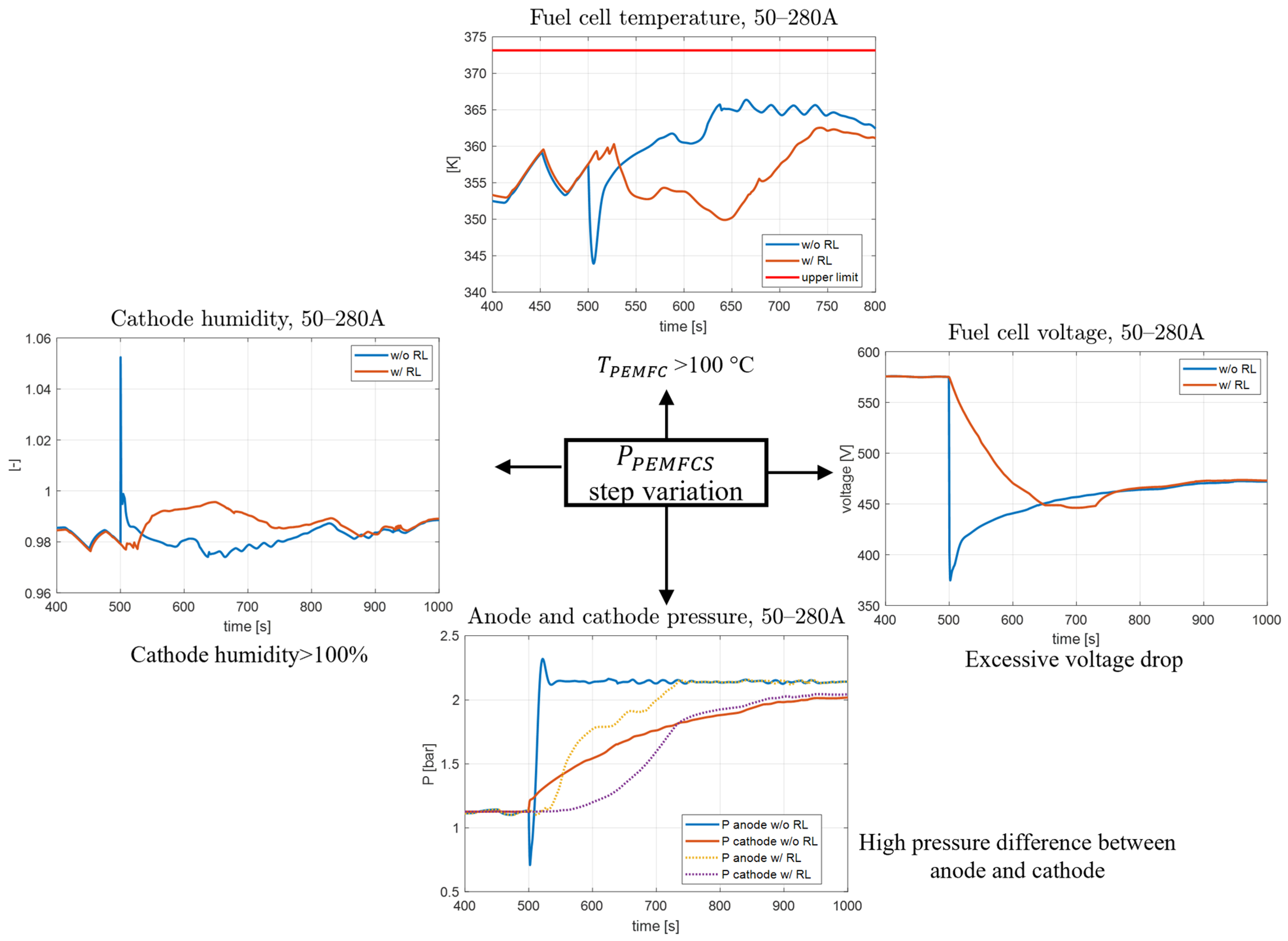
Additionally, it is important to note that the significance of limiting the PEMFCS power slope has also been investigated by incorporating the thermostatic controller into the comprehensive multi-dimensional model described in [
54]. The latter, which is aimed at boosting the development of energy management strategies for heavy-duty vehicles, includes a detailed PEMFCS physical model, through which the benefits of managing transients via a properly defined RL can be appreciated. It is also worth mentioning here that the aforementioned physical model was not used in the core of this manuscript. Specifically, with reference to the model and application context of [
54],
Figure 3 presents two scenarios featuring a transient at 550 s, where the requested
moves in one case from 50 A to 280 A instantaneously, while in the other case the dynamics are managed through an RL. The latter situation implies the following favorable benefits for PEMFC operating parameters:
Cathode humidity is kept below 100%, thus avoiding flooding;
Excessive stack voltage drop is avoided;
The pressure difference between cathode and anode is minimized, which provides benefits in terms of mechanical resistance;
The rapid decrease of the stack’s operating temperature is prevented.
Finally, it is important to note that quantitative assessment of PEM fuel cell degradation is typically addressed in the literature via semi-empirical approaches that account for coefficients associated with operating conditions featuring an output power less than 5% of the maximum, a full start–stop, a load variation rate larger than 10% of maximum power per second, and a power supply higher than 90% of the maximum [
55]. Therefore, the degradation-aware control policy presented in this section can definitely contribute to extending the durability of PEM devices. Other approaches, such as the one detailed in [
56], include dynamic equivalent circuit-based degradation models that account for the charge double layer effect to estimate the fuel cell stack’s state-of-health over a certain operating period.
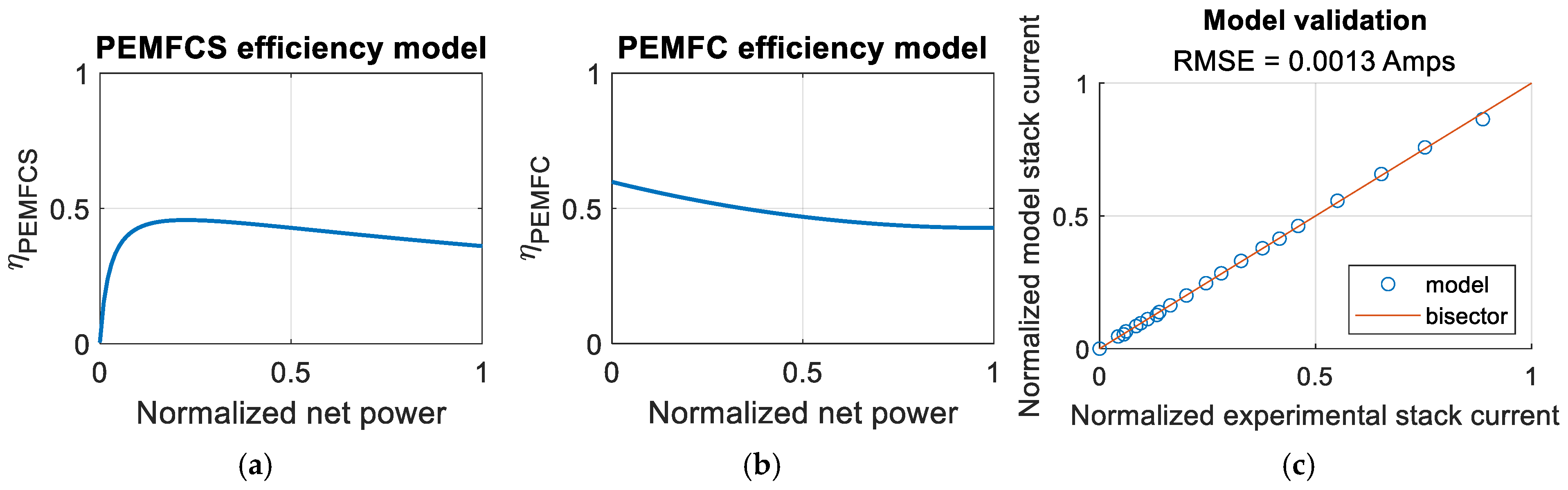
2.4. Efficiency-Driven Model
The PEMFCS integration within the aircraft’s electrical architecture requires a thorough evaluation of both
and
. This assessment is essential to ensure optimal performance and reliability, as well as to ensure that the system meets the operational and safety requirements specified for the aircraft. To tackle this issue, as an alternative to traditional approaches, a model is proposed that evaluates the aforementioned variables relying on control strategy requirements and efficiency curves (see
Figure 4a,b), the latter defined into an operating range that meets the key performance indicators set by the CH2E-SRIA as discussed above in
Section 2.1. Moreover, being designed to integrated simulation framework deployment, another goal of the PEMFC voltage and current estimator could be to automatically update such evaluations as a function of different stacks, e.g., manufactured by a new supplier, for which efficiency curves might only be available. The efficiency-driven model has been conceived according to the following simplifying assumptions:
The model is grey-box and steady-state. However, PEMFCS dynamics are suitably accounted for via the introduction of a power RL, as detailed in the previous section;
Dead-end operation. Thus, additional hydrogen consumption is neglected, and a unitary utilization factor is considered;
Constant operating temperature.
It is worth remarking here that the model is derived by accounting for two input parameters, which are the PEMFCS rated power, since the efficiency curves are used in a normalized form, and the number of cells. As for the latter parameter, which is defined in Equation (13), it also depends on the number of stacks operated in parallel to accommodate the required voltage and current levels.
Particularly,
is calculated via Equation (12), which defines stack efficiency (
) as the ratio of the actual voltage to the product between the stack’s total number of cells (
) and thermoneutral voltage (
), equal to 1.48 V [
57]. Furthermore, it is worth remarking that, although Equation (12) represents a well-established relationship in the thermodynamic analysis of fuel cell systems, the key contribution of this study lies in inverting the relationship and leveraging the linkages between
and PEMFCS normalized net power to estimate
. The number of PEM fuel cells
is calculated through Equation (13), as the ratio of the nominal installed power to that associated with a virtual PEMFCS consisting of a single cell (
), considered here to be 0.27 kW, in accordance with the experimental set-up available at the University of Salerno premises.
On the other hand, Equation (14) delineates the mathematical relationship between
and
, which are linked via the system-level efficiency (
), whose behavior is described in
Figure 4a as a function of the normalized net power. It is noteworthy that Equation (14) is derived from manipulating Equations (2), (12) and (14), the latter expressed in terms of hydrogen molar flow rate (
). Specifically, Equation (14) corresponds to Faraday’s law, in which
is the number of electrons involved in the electrochemical reaction (i.e., 2 for hydrogen) and
is Faraday’s constant.
It is also important to specify that
is calculated by accounting for the PEMFCS power supply at sea level, such that physical considerations are respected. Indeed, as the altitude increases,
decreases at the same current. The same reasoning is also applied to Equation (2) to estimate hydrogen consumption. Particularly, in
Figure 4, the sea-level PEMFCS efficiency, as a function of which hydrogen consumption is computed, refers to the value upstream the multiplication by the altitude-dependent correction factor expressed by Equation (9).
The validation of the efficiency-driven model is presented in
Figure 4c, wherein the modeled
is compared with experimental results on the plane experimental-predicted data, resulting in a root-mean squared error (RMSE) of 0.0013 Amps. It is worth remarking here that the tested PEMFCS can yield > 1 kW of electric power at nominal conditions at an average operating temperature of about 80 °C. The data shown in
Figure 4c belongs to the current range defined by the supplier to fully describe the FCS performance as a polarization curve. The proposed model is versatile enough to be suitably applied to a different PEMFCS so as to enable safe replication of the presented validation methodology on the final technology that will be selected for the aircraft. Moreover, as shown in
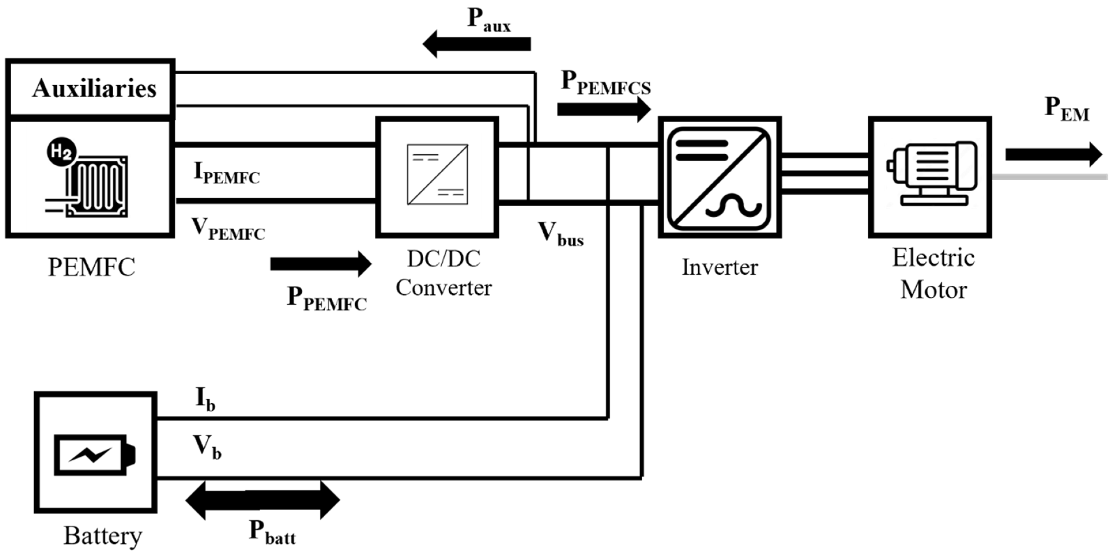
Figure 5, auxiliaries are considered to operate at the bus voltage level (
) and the corresponding power absorption is calculated relying on Equation (16).
where
represents the DC/DC converter efficiency, equal to 0.98 [
58], a value compliant with aviation standards for highly efficient and reliable power conditioning devices.
According to [
57], Equation (17) exploits the profiled
to calculate the rate of heat generated by the stack (
), which increases during high-current and low-voltage operations, thus providing useful information for the sizing of an effective cooling system while also allowing for monitoring the ratio between electrical power output and generated thermal power.
Additionally, following [
59], Equation (18) is employed to calculate the cooling system load. In [
59], a Sankey diagram is proposed to relate the stack’s power output to the stack’s heat generation rate, emphasizing the crucial role played by the water vapor evaporation. Based on these assumptions,
is determined on an HHV basis, while the actual cooling load (
) must be evaluated relying on the lower heating value (LHV) to account for the thermal energy required to evaporate the water generated during the operational process. Therefore,
, equal to 1.25, is introduced in Equation (18).
3. Application of the Mathematical Tool to a Realistic Case Study
The two-level structured mathematical tool is applied to the load profile shown in
Figure 6a. It is worth noting that, although the tool is here applied to an aeronautical load profile, it could be extended to various application fields and fuel cell technologies. This possibility is offered by the flexibility of the BRBC, which is deployable to assess the PEMFCS power supply in light-duty [
46] and heavy-duty fuel cell-based vehicles [
60] scenarios. Indeed, once the nominal size of the PEM fuel cell is established, the power allocation between hybridizing components is achievable by relying on the specific-independent control strategy described in
Section 2.3. Finally, the efficiency-driven model can be used to estimate electrical variables of the specific fuel cell technology (e.g., SOFCs or high-temperature PEMFCs) by changing the normalized efficiency curves of the device and properly accounting for the fuel utilization.
In the present study, the preliminary sizing procedure accounts for the data provided in
Table 2. Therefore, the selected 730 kW PEMFCS and 2100 kW electric motor resulted in
of 1833 kW and a capacity at pack level (
) of 578 kWh.
Table 2 also indicates that the degradation-aware control strategy constrains the maximum PEMFCS deliverable power to 500 kW to prevent high-load operations and ensure consistent power output throughout the device’s lifespan. Such an oversized PEMFCS is fully aligned to a recent degradation-aware design approach, which was proven effective for improving fuel economy as well [
61]. Furthermore, from the control perspective, the following assumptions are considered:
It is worth mentioning here that the selection of
and
is closely tied to the requirement of achieving a SOC at the end of the flight mission (
) of approximately 20%, while fully exploiting the battery’s contribution during high-power phases. The energy management outcomes, resulting from the implementation of the BRBC strategy, are schematically summarized in
Table 3 and shown in
Figure 6b,c. Particularly, during taxi-out and take-off phases, the PEMFCS operates at the maximum admitted power level of 500 kW; thus, the high-power mode is active (see
Section 2.3) in the time window [0, 270] s. After this initial stage, the power demand still exceeds the threshold of 1800 kW; then the PEMFCS should continue to provide 500 kW. However, due to the altitude changing during the climb, the
modulates the PEMFCS output power following a quasi-linear trend. The maximum net power reduction is attained at the cruising altitude (i.e., 4600 m), where a performance drop with respect to sea level power of approximately 10% is observable. Moreover, as visible from the red-dotted line in
Figure 6b, the stack power (
) is not affected by the altitude effect and follows the trend originally established by the BRBC.
At the beginning of the cruising phase (i.e., around 1000 s), the battery mode is entered due to the actual SOC being higher than
(see
Figure 6c). Particularly, the PEMFCS delivers 150 kW, a value 5.3% lower than that obtainable at an altitude of zero. The hybrid mode is then initialized from 1000 s to 4650 s, with the PEMFCS working at the power level imposed by the denormalized control maps that is scaled by the
equal to 6.5%. In such an operating condition, the PEMFCS is able to entirely fulfill the load while also recharging the battery up to
. Therefore, battery mode is reactivated, but a slow decreasing trend can be observed in the SOC owing to the PEMFCS power supply approaching the load demand. A variation in the power delivered by the PEMFCS can be outlined in
Figure 6b from 7300 s to 7900 s that is attributable to the reduction of altitude in the descent phase. Particularly, despite operating in idling, the PEMFCS can provide more power due to the reduced altitude and decreased auxiliaries’ absorption. In the last phases of the mission (i.e., landing and taxi-in), the high-power mode set the PEMFCS to operate at 500 kW, while the SOC diminishes to satisfy the load request.
Finally, this control scheme is achieved by consuming 29.43 kg of hydrogen (i.e., 1160 kWh of hydrogen energy), which is approximately 4% higher than that attained when neglecting altitude effects. Therefore, it is worth remarking here that the mass of hydrogen is calculated via Equation (2) by considering the power the system is able to deliver at standard condition and efficiency at zero altitude. Subsequently, the efficiency in-flight shown in
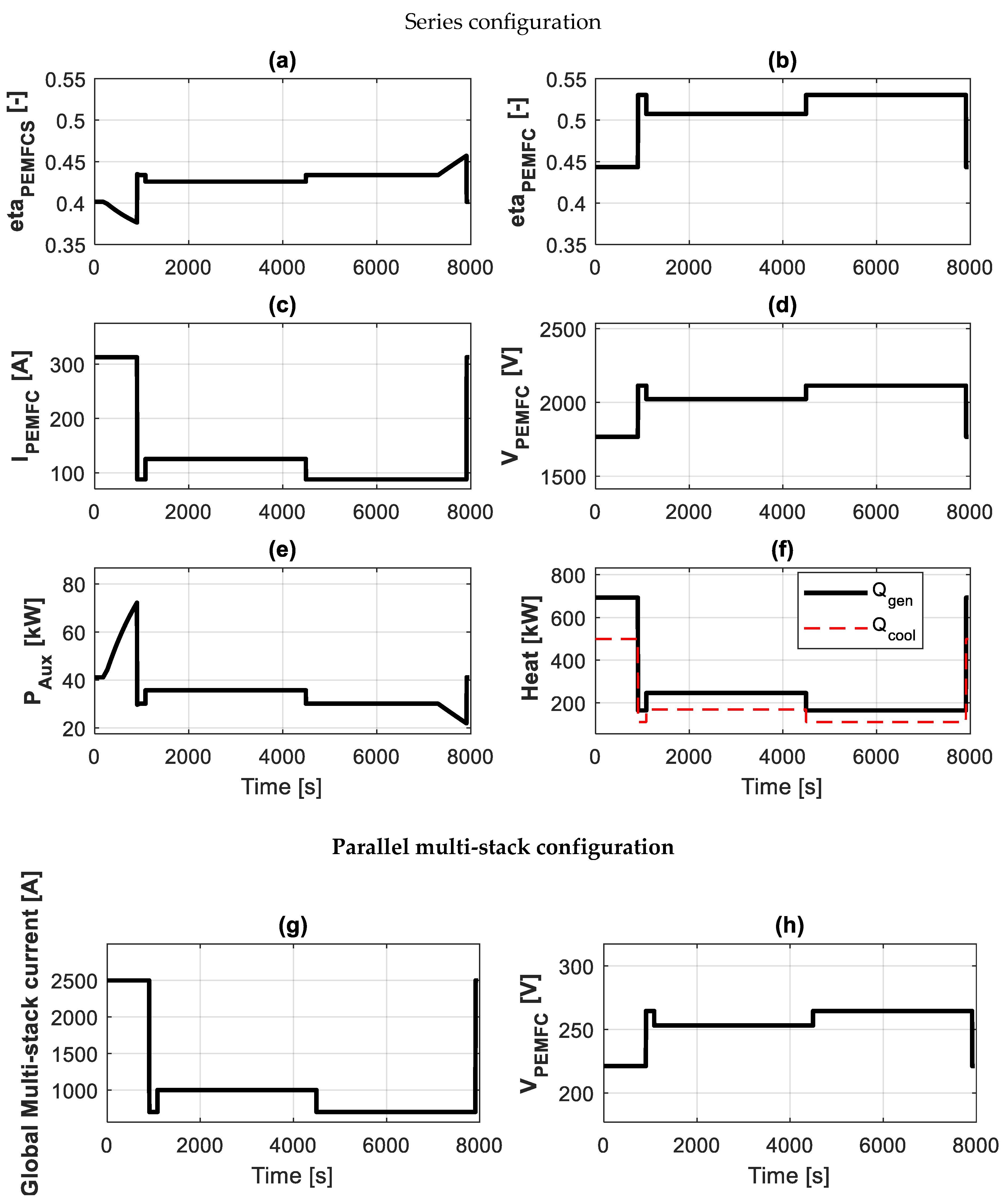
Figure 7a is calculated by leveraging the hydrogen consumption outcome and PEMFCS actual power supply that depends on altitude.
Particularly, the PEMFCS efficiency moves from 0.4 to 0.37 during the initial high-power phase owing to the altitude passing from 0 m to 4600 m. In cruising, the efficiency moves between 0.42 and 0.43 in the battery and hybrid modes, respectively. Furthermore, following the trend of the PEMFCS power, the efficiency is enhanced in landing owing to the altitude approaching sea level. Conversely, the efficiency of the stack presented in
Figure 7b is not affected by such effects.
The PEMFCS power profile obtained through the BRBC strategy is used as input for the efficiency-driven model to estimate the stack’s electrical variables upstream of the DC/DC converter.
Figure 7c shows that,
attains its maximum value of 312 A in high-power phases. However, although in such stages it is kept constant, the PEMFCS delivered power is reduced. In the other time windows,
is equal to 88 A (i.e., battery mode) and 125 A (i.e., hybrid mode).
On the other hand,
exhibits its minimum of 1767 V during high power, while oscillating between 2022 V and 2114 V in hybrid and battery modes, respectively. At this stage, it is important to note that voltage fluctuations observable in the various flight segments (see
Figure 7d) are closely dependent on energy management choices, which account for transients related to degradation actions and maximum efficiency idling level, as comprehensively discussed in
Section 2.3.2.
High current operations also result in an increased balance in the plant’s absorption, which attains its maximum for the maximum PEMFCS power at the end of cruising phases. Particularly, for the same , auxiliary power consumption passes from 40 kW to 73 kW, exhibiting an increase of 82.5%. Such a figure is reduced to 31 kW and 37 kW during battery and hybrid modes, respectively, due to the lower requested. It is important to note that the overall PEMFCS efficiency could be potentially improved by oversizing the system or changing the stack’s operating current so as to minimize the parasitic power absorbed by the compressor, the latter sized to accommodate the requested air mass flow rate at maximum altitude and current.
Moreover, the reduced PEMFCS efficiency throughout low
and high
working conditions brings about an increased heat generation rate, whose maximum value is 690 kW, while its minimum, achieved in battery mode, is less than 200 kW (
Figure 7f).
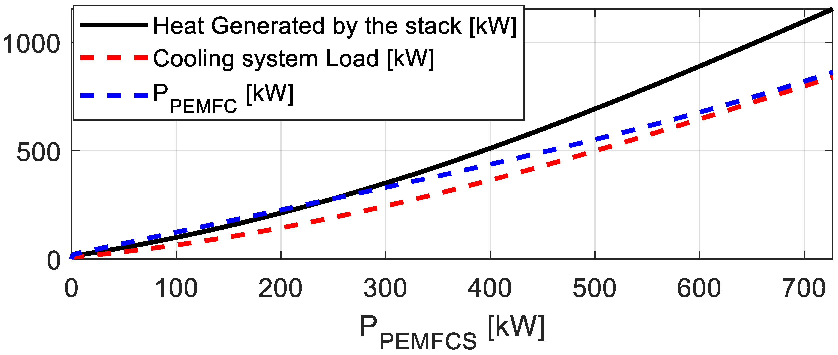
Figure 7f also displays the cooling system load, which is scaled down relatively to the total heat generated to account for the internal water evaporation. In this regard, a graph showing the trajectories of the stack’s power (
),
and
as a function of the PEMFCS net power output is provided in
Figure 8, wherein two regions can be distinguished. Indeed, for
lower than 280 kW, the stack’s electrical power output is always higher than the amount of heat generated. Conversely, when
overcomes 280 kW, the heat generated overcomes the electrical power output, implying an increased cooling system load. In the scenario analyzed here, a cooling system capable of removing at least 500 kW is required. This value is aligned with the state-of-the-art results (i.e., MW levels of cooling load) presented in [
15,
62], demonstrating that thermal management is a major challenge for the viability of hydrogen-based hybrid electric aircraft. For this reason, advanced cooling options [
15] and high-temperature PEMFCS are also currently investigated for aeronautic purposes [
63].
It is noteworthy that such results offer the possibility of customizing both the hybrid unit’s design and energy management strategy through selecting the PEMFCS operating power level depending on the cooling system’s requirements. In this way, a trade-off can be achieved between PEMFCS installed power and cooling system nominal size in order to guarantee, on one hand, efficient operation of the hydrogen-based device and, on the other hand, reduced gravimetric and volumetric impacts of the thermal management system. To this end, multi-objective optimization can be carried out to explore the aircraft’s design space. Indeed, based on the selected control strategy and the typical operating efficiency of a hydrogen-fueled device, a larger PEMFCS would generate a significant cooling load during the initial phase of the mission while ensuring higher efficiency during cruising compared to a smaller PEMFCS. Conversely, the latter configuration would result in a reduced cooling load at takeoff but would potentially entail lower operational efficiency over the other flight stages, affecting hydrogen consumption and, consequently, the mass of the tank. Therefore, in view of reducing the aircraft’s maximal take-off mass, the model could be potentially embedded in a procedure aimed at generating Pareto’s frontier to select the sizes of hybridizing components to reach out a solution that respects the thermal management system’s constraints and also ensures adequate PEMFCS operational efficiency, which guarantees increased durability for the system (as discussed in
Section 2.3.2).
Moreover, with the coupling between the above-described cooling requirement map (see
Figure 8) and the versatile, efficiency-driven model proposed here, the designer can easily and automatically adapt cooling needs to different stacks exhibiting improved performance and power-to-weight ratio, e.g., those fulfilling the future KPI targets set by the CH2E-SRIA [
8]. For instance, if the aforementioned (see
Section 2.2.1) 0.65 V single cell voltage target is obtained at current values considerably higher than 1 A/cm
2, it means that at the same current higher power and lower cooling demand and number of cells will occur, respectively; on the other hand, in case the nominal current is increased until the 0.65 V limit, then the number of cells would decrease further, thus helping to achieve the challenging power-to-weight ratio values required for aviation, provided that the health and lifetime-related issues induced by high operating current PEMFC functioning are suitably accounted for [
8]. Furthermore, this versatile tool will also allow, by virtue of integrating the model into the overall digital twin, to directly account for the variation in thermal load as the hybrid unit’s configuration tested in simulation changes. Consequently, the cooling system can be designed and optimized accordingly.
It is worth noting at this point that the current fuel cell system design outcomes rely on a configuration featuring a series connection between the 2693 cells making up the stack, as outlined in
Table 4. Therefore, to reduce both the single stack’s number of cells and maximum
, a second-level design has been carried out by constraining the maximum
on the DC line before the converter to 270 V. This is a typical value used in aviation DC powertrains downstream of the DC conversion stage for reliability in transient conditions [
64,
65]; it was thus selected here so as to ensure the converter does not have to face issues due to large voltage changes.
The second-level design is therefore conceived to enable multi-stack operation, which allows for reducing the maximum voltage while keeping the same nominal PEMFCS power utilized in case of all cells in series configuration. Moreover, as outlined in [
29], this architecture provides significant advantages over single-stack solutions, particularly in terms of spatial flexibility, redundancy, and overall reliability. Indeed, the possibility of easily moving from a single stack to a multi-stack configuration depending on the requested voltage demonstrates the flexibility of the proposed efficiency-driven model.
Hence, as visible in
Table 4, eight stacks operating in parallel, each including 337 cells, have been assumed to reduce the maximum
from approximately 2114 V to 265 V.
Figure 7h shows that, in the multi-stack configuration, the general trend of the stack voltage remains the same, but it is scaled by a factor of 8 with respect to all cells in the series architecture. Conversely, the maximum value of the single stack current remains 312 A, but the global current increases by the same factor to guarantee the same PEMFC power output. This depends on the fact that the stack’s single-cell working point is the same between single-stack and multi-stack arrangements; consequently, the overall efficiency is not changed between the two aforementioned scenarios, as well as the remaining variables outputted by the efficiency-driven model.
Finally, the total mass and volume of the powertrain are determined via the contributions presented in
Table 5. It is important to note that to account for the alternate and loiter phases, the mass of hydrogen increases by 20% with respect to that necessary for the mission, thus also impacting the tank’s mass and volume. As a final result, it can be deduced that the proposed design and control strategy assumptions respect the constraints of 3600 kg and 3 m
3. It is notable that the hybrid unit’s total volume and mass remain unchanged between single-stack and multi-stack scenarios owing to the approach used for evaluating PEMFCS gravimetric and volumetric impacts, which relies on the KPIs listed in
Table 1.
With respect to the latter aspect, it is worth remarking here that significant technological and methodological innovations are highly strategic in the design phase to cope with transportation systems requirements [
66].
Therefore, the results demonstrate the suitability and flexibility of the proposed mathematical tool in evaluating electrical variables for different stack arrangements. Moreover, owing to its reduced calculation time, the model can be fruitfully integrated into the aircraft’s comprehensive simulation framework, being also adaptable to digital twin specifications. For instance, the efficiency-driven methodology is usable as a real-time simulator of a fully healthy system, facilitating model-based diagnosis analysis via the comparison between modeled voltage values and those obtained from sensors placed downstream of the stack. On the one hand, this facilitates remaining-useful life estimation, while on the other hand, combined design and energy management actions contribute to meeting the same load requirements at both the beginning and the end of life.
It is worth noting that the integration of the model within the aircraft’s digital twin would be possible by means of existing communication standards for model exchange or co-simulation. Consequently, the interaction of the digital twin with the physical system would allow areas for improvement in the model to emerge, highlighting its weaknesses.
4. Conclusions
The manuscript presented a model-based mathematical tool, comprising a degradation-aware energy management strategy and an electrical variables estimator for aeronautical PEM fuel cell systems, to be integrated within integrated simulation frameworks for regional aircraft. A rule-based strategy was conceived to induce blended control of the hybridizing battery pack, also aiming at increasing the fuel cell system’s durability by implementing degradation-aware management of critical transient maneuvers. These include high and low-power phases and start-and-stop operations, which have been limited by constraining the fuel cell system deliverable power between a minimum idling level and a maximum power level. Specifically, in order to reduce hydrogen consumption and increase fuel economy, the idling has been selected in correspondence with the maximum fuel cell system efficiency point. The overall energy management strategy is ‘blended’, meaning that the fuel cell system operates at its maximum admitted power during take-off and landing, while the rule-based thermostatic battery energy management is employed throughout the remaining flight stages. Additionally, rapid transients that also contribute to system degradation have been managed through a power rate limiter, which bounds the PEMFCS power slope at a maximum rate of 10% of the installed power per second.
Besides the novelties introduced from the energy management perspective, another key contribution of the work deals with the development of an efficiency-driven model to estimate the stack’s electrical variables (i.e., voltage and current) upstream of the DC/DC converter. Such a grey-box model relates electrical variables to the PEMFCS power supply via simple mathematical relationships leveraging the availability of experimentally derived efficiency curves at both system and stack levels. Moreover, the efficiency-driven model’s distinguishing features, compared to other-reduced order model approaches, involve the estimation of auxiliaries’ power absorption, the latter considered to operate at the bus voltage level, as well as providing useful information for the balance-of-plant preliminary sizing. The absorption of ancillaries calculated here was also accounting for the impact that varying altitude has on the net power delivered by the fuel cell system.
Further information retrievable from the efficiency-driven model includes the rate of heat generated by the stack, corresponding cooling loads, and hydrogen consumption. Indeed, the fuel cell system cooling load is directly estimated as a function of the fuel cell system output power so as to provide the designer with an easy-to-use and versatile cooling load versus nominal PEM fuel cell system performance map. This information is crucial for the preliminary sizing of the cooling system, since various design and energy management choices can be made to achieve a viable trade-off between the fuel cell system’s deliverable power and the cooling system’s added mass and volume.
Additionally, the flexibility of such a model should also be evident. In fact, it is potentially capable of simulating the stack’s current and voltage of different fuel cell manufacturers by only modifying the efficiency curves inside the tool. The same approach is exploitable to account for altitude and pressure effects in the case of non-environmentally controlled environments, which can be thus considered via experimentally derived curves, as well as following the technological evolution that is foreseen for effective integration of low-temperature fuel cells on board future cleaner hybrid aircraft. It is then worth highlighting the fact that, to the authors’ knowledge, it is the first time that manufacturers efficiency curves are exploited to derive, through the proposed modeling approach, design-oriented performance maps that allow for accounting for both performance and cooling demand, with the final aim of finding the best system configuration for proton exchange membrane fuel cell units. Future development will of course also include fruitful interaction, within multi-level models hierarchy, with more accurate models of PEM fuel cell polarization curves, so as to address specific needs, such as the need for a more careful accounting for cell-level effects, such as unpredictable boundary (e.g., environment-related) conditions, as well as unexpected degradation and/or faulty behaviors.
The conceived mathematical tool has been applied to a realistic case study, which considers a representative electrical load demand for a hybrid regional aircraft. Hence, using the sizing procedure and scenario assumptions from [
42], the blended rule-based control strategy results in a hydrogen consumption of approximately 29.4 kg. The latter outcome strictly depends on the fuel cell system oversizing and the selected power level, which on the one hand helps to mitigate degradation and on the other hand allows the device to operate at relatively high efficiency throughout the entire mission. The resulting PEMFCS power profile, which accounts for the performance drop at various altitudes, is then used as input of the efficiency-driven model to estimate electrical variables. Specifically, the current follows the system’s efficiency trend and exhibits its maximum value of 312 A during high-power phases, while oscillating between 90 and 120 A in the remaining flight time. On the other hand, according to physical considerations, the voltage exhibits its minimum during take-off and landing (i.e., 1767 V) and its maximum during idling mode (i.e., 2114 V). High-power operations also influence the power absorbed by the auxiliaries that attain the maximum (i.e., approximately 60 kW) when cruising altitude is achieved and maximum power is delivered, while consuming approximately 30 kW in the remaining ones. As for the rate of heat generated by the stack, it increases as the current decreases and voltage increases. The maximum thermal power generated by the stack amounts to approximately 690 kW, resulting in a cooling system that should be capable of removing at least 500 kW. Furthermore, a second-level design has been introduced. Indeed, to cope with the 270 V constraint on the DC line, eight stacks operating in parallel have been considered.
In future studies, the proposed mathematical tool will be utilized to implement a degradation-aware design that accounts for voltage decay after a specified number of flight hours. The objective is to ensure that the fuel cell system can meet the power demand decided by the control strategy even at the end of its operational lifespan, i.e., when a certain stack’s voltage drop occurs. This implies that the voltage output of the efficiency-driven model will be suitably corrected to account for the earlier mentioned voltage drop. To this end, as an intermediate step, it is essential to quantify the degradation throughout the flight mission, which can be achieved, for instance, by employing semi-empirical or time-varying degradation approaches available in the literature. This will require a model improvement to also account for the temperature of hybridizing components. Moreover, in the multi-stack configuration, different working points between each stack could be considered in order to optimize the system’s lifetime via properly defined energy management actions. This could require carefully sizing the balance of plant components, which can impact the total hybrid unit’s mass.
As a final step, the integration of the model at the aircraft system level and the resulting digital twin could allow for refining the dimensioning process, also considering the snowball effect. Particularly, this would allow us to properly account for the impact on the actual flight profile of the selected hybrid unit’s size, energy management, and resulting cooling demand.


