Abstract
This paper introduces a novel energy management framework, Deep-Fuzzy Logic Control (Deep-FLC), which combines predictive modelling using Long Short-Term Memory (LSTM) networks with adaptive fuzzy logic to optimise energy allocation, minimise grid dependency, and preserve battery health in grid-connected microgrid (MG) systems. Integrating LSTM-based predictions provides foresight into system parameters such as state of charge, load demand, and battery health, while fuzzy logic ensures real-time adaptive control. Results demonstrate that Deep-FLC achieves a 25.7% reduction in operational costs compared to the conventional system and a 17.5% saving cost over the Fuzzy Logic Control (FLC) system. Additionally, Deep-FLC delivers the highest battery efficiency of 61% and constraints depth of discharge to below 2% per time step, resulting in a reduction of the state of health degradation to less than 0.2% over 300 h. By combining predictive analytics with adaptive control, this study addresses the limitations of standalone approaches and establishes Deep-FLC as a robust, efficient, and sustainable energy management solution. Key novel contributions include the integration of advanced prediction mechanisms with fuzzy control and its application to battery-integrated grid-connected MG systems.
1. Introduction
As the integration of renewable energy sources (RESs), particularly solar photovoltaic (PV) systems, into residential energy infrastructures increases, significant opportunities for reducing carbon emissions and energy costs are presented [1]. However, this transition to renewable energy introduces challenges, including fluctuating power generation, mismatches between supply and demand, and the degradation of energy storage systems (ESSs) such as batteries [2,3]. As modern energy systems become more reliant on batteries to stabilize energy flows and store surplus energy, the need for intelligent energy management strategies has become imperative [4,5].
Traditional Energy Management Systems (EMSs) in residential applications often use static control schemes, which rely on predefined thresholds for charging and discharging batteries [6]. Whilst these methods are much less complicated, they fail to adapt to dynamic changes in load demand, the unpredictability of renewable energy generation, or uncertainty in grid conditions. Consequently, static control leads to inefficiencies such as increased reliance on grid power during peak hours, suboptimal battery utilisation, and accelerated battery degradation [7,8]. To overcome these limitations, Fuzzy Logic Control (FLC) has been introduced and shown to be a promising approach for energy management due to its adaptive capabilities in real-time scenarios [9,10].
Despite FLC systems’ success, their inability to predict near future energy demands and supply variations limits their effectiveness in addressing uncertainties in renewable energy integration [11,12]. Recent advancements in machine learning (ML), particularly Long-Short-Term Memory (LSTM) networks, offer powerful predictive capabilities that can enhance energy management [13,14]. However, the integration of predictive models along with LSTM with adaptive control methods such as FLC remains unresearched and needs to be explored [15]. This integration could enable proactive energy management by forecasting energy trends in real time and adjusting battery operations dynamically, as appropriate, to minimise costs and improve efficiency [16,17].
Therefore, this study introduces a novel Deep-Fuzzy Logic Control (Deep-FLC) framework that combines the predictive power of LSTM models with the adaptability of fuzzy logic systems. The proposed Deep-FLC system aims to address key challenges in energy management, including fluctuating renewable energy supply, high operational costs, and battery degradation. The framework is designed to minimise energy costs, reduce reliance on grid power, particularly in periods of high demand, and extend battery lifespan by optimising battery operations in real time. These aims will be achieved through the following objectives:
- To design and implement a novel Deep-FLC framework that integrates predictive LSTM models with fuzzy logic to optimise battery energy management.
- To evaluate and compare the performance of three systems—conventional, FLC, and Deep-FLC—using key performance metrics, including total cost, battery efficiency, State of Health (SOH), and Depth of Discharge (DoD).
- To minimise energy costs and reduce reliance on grid power by dynamically adjusting charging and discharging priorities based on real-time battery conditions and predicted energy demands.
- To enhance battery lifespan by reducing DoD and ensuring stable State of Charge (SOC) levels, thus minimising stress on the battery system and lowering degradation rates.
1.1. Purpose
The purpose of this paper is to develop an advanced energy management framework that leverages the strengths of Deep-FLC by combining the adaptability of fuzzy logic with the predictive power of LSTM models. The proposed system is designed to optimise the use of residential battery energy storage systems (BESSs), reduce dependency on the grid-connected microgrid (MG), and minimise operational energy costs. By employing real-time adaptive control and predictive modelling, this research seeks to address the challenges of fluctuating energy demands, variable renewable energy supply, and battery degradation.
1.2. Research Gaps in Energy Management for MGs
Despite advancements in EMSs, several critical challenges remain unaddressed as follows:
- Static control in conventional systems:Traditional energy management approaches are often based on fixed thresholds for battery charging and discharging. These static methods lack the flexibility to adapt to highly dynamic energy demand; uncertain renewable energy generation, irrespective of whether PV systems or wind turbines (WT) are used; and battery conditions, leading to inefficiencies.
- Limitations of existing FLC systems: Whilst providing adaptability to certain conditions, FLC does not incorporate predictive capabilities. As a result, these systems struggle to respond proactively to sudden changes in load demand, renewable energy availability, or grid constraints.
- Neglect of battery degradation and long-term sustainability: Current EMSs often fail to adequately account for key factors such as SOH and DoD, both of which are essential for extending the battery lifespan and ensuring long-term system efficiency.
This research introduces the Deep-FLC system, which combines LSTM-based predictions with fuzzy logic to achieve proactive and adaptive energy management in residential BESSs, to address the research gaps identified by the literature review presented in more detail in the next section.
This paper is structured as follows: The literature review in Section 2 highlights existing studies in energy management focusing on static control, FLC systems, and ML integration. Section 3 delves on the methodology that explains the design and implementation of the Deep-FLC system, including its predictive and adaptive components. Section 4 and Section 5, respectively, show the results and discussion and evaluate the system’s performance compared to baseline methods. Finally, Section 6 summarises the findings and implications for grid-connected applications.
2. Literature Review
Static control systems represent one of the earliest approaches to energy management in battery-integrated energy systems. These systems operate by enforcing predefined, fixed rules for charging and discharging batteries based on thresholds for parameters such as the SOC and DoD [18,19]. For instance, the battery may be programmed to begin charging when the SOC falls below a certain percentage, typically 30%, and to stop charging when the SOC exceeds an upper threshold, typically 90%. These thresholds are defined by the manufacturer of Cadex [20]. This simplicity makes static control systems relatively easy to implement and computationally efficient [21]. However, these systems suffer from significant limitations, particularly in the context of renewable energy integration, where energy supply and demand vary dynamically. The inflexibility of static control results in suboptimal battery usage, particularly during periods of high renewable energy generation or fluctuating load demand [22]. For example, static control systems often fail to prioritise renewable energy utilisation during peak production, leading to increased reliance on grid power. This not only increases operational costs but also reduces the overall efficiency of the energy system. Additionally, static control systems are prone to frequent deep discharges, accelerating battery degradation and reducing the SOH over time [23]. Empirical studies provide ample evidence of the limitations of static control. Brandi et al. [24] highlighted how static systems underperform in dynamic environments with RESs, reporting higher energy costs and greater grid dependence compared to adaptive control methods. Similarly, Shamarova et al. [25] demonstrated that static control leads to significant battery wear due to its inability to respond to real-time energy conditions. In scenarios where solar power generation fluctuates throughout the day, static systems often force the battery into rapid charge and discharge cycles, exacerbating wear and reducing lifespan.
FLC systems were developed as an adaptive approach to energy management to address the shortcomings of static control [26]. Unlike static systems, FLC leverages fuzzy logic rules to manage uncertainties and make decisions based on multiple input parameters, such as SOC, DoD, load demand, and energy costs [27]. FLC systems are particularly well-suited for handling the inherent variability and unpredictability of RESs, as they can adjust battery operations in real time. The flexibility of FLC systems lies in their ability to interpret input parameters within a range of values rather than relying on rigid thresholds. For example, rather than triggering battery charging at a fixed SOC of 30%, an FLC system might assign a high charging priority when SOC is low, medium priority when SOC is moderate, and low priority when SOC is high. This gradation enables more nuanced and efficient battery management, reducing unnecessary cycling and improving energy efficiency [28]. Studies have demonstrated the effectiveness of FLC systems in enhancing energy management. Whig et al. [29] showed that FLC systems could reduce operational costs by prioritising renewable energy usage and minimising grid dependence during peak hours. Liu et al. [30] similarly reported improvements in battery longevity due to the adaptive control of DoD, which prevented excessive deep discharges. However, FLC systems are inherently reactive, responding to current conditions rather than anticipating future energy trends. This reactive nature limits their ability to optimise energy management proactively, particularly in scenarios with significant variability in renewable energy supply or load demand [31].
Recent advancements in ML have introduced new possibilities for energy management, particularly in predicting energy demands and renewable energy generation. Deep learning models, such as Long Short-Term Memory (LSTM) networks, have proven particularly effective in time-series forecasting, making them well-suited for predicting load demand and solar power generation [32,33]. LSTMs, a type of recurrent neural network, excel at capturing long-term dependencies in sequential data, significantly improving the predictions over extended time horizons [34,35]. ML-based predictions can significantly enhance energy management by providing foresight into future energy conditions. For example, Pang et al. [36] used LSTMs to predict solar power output with high accuracy, enabling energy systems to pre-emptively allocate resources and reduce grid dependence. Zheng et al. [37] applied similar models for load forecasting, demonstrating how more accurate predictions could optimise battery charging schedules to align with periods of high renewable energy generation. However, ML models alone cannot manage energy systems directly. Whilst excelling at prediction, ML models lack the capability to adaptively control battery operations in real-time. As a result, standalone ML models must be integrated with control systems to achieve practical energy management [38]. Without this integration, predictions from LSTM models may remain unable to meet their potential, limiting their impact on overall system efficiency and benefiting from lower costs.
By combining the predictive capabilities of deep learning models with the adaptability of FLC, the integration of ML with FLC systems has emerged as a promising approach to energy management. Hybrid systems address the limitations of standalone methods by enabling proactive and dynamic energy management. For instance, predictions from LSTM models can be used to adjust fuzzy logic rules dynamically, ensuring that battery operations align with anticipated energy trends [39,40]. Han et al. [41] explored the integration of LSTM predictions with FLC systems for renewable energy management, reporting significant improvements in cost reduction and grid independence. Similarly, Li et al. [42] demonstrated how hybrid systems could minimise battery degradation by proactively adjusting DoD thresholds based on predicted load demand. Despite these advancements, most existing hybrid systems use predictions from ML models as static inputs for FLC systems rather than enabling deep integration between the two components [43].
Therefore, the proposed Deep-FLC framework in this study aims to address the identified research gaps by deeply integrating LSTM predictions with FLC systems. Unlike traditional hybrid systems, the Deep-FLC framework uses predictive insights to modify fuzzy logic rules in real time, enabling both proactive and adaptive control. This deep integration enhances the efficiency, reliability, and cost-effectiveness of energy management, making it particularly suitable for residential applications with high renewable energy penetration.
This study builds on the limitations identified in the existing literature by proposing the Deep-FLC framework, which deeply integrates LSTM-based predictions with FLC systems. Unlike previous approaches, the Deep-FLC system uses predictive insights from LSTM to adjust fuzzy logic rules dynamically, enabling proactive and adaptive energy management simultaneously. By addressing key challenges such as cost reduction, battery degradation, and grid independence, the Deep-FLC framework represents a significant advancement in energy management for residential applications.
3. Proposed Framework and Methodology for Deep-FLC Implementation
This section presents the methodology for evaluating the following three EMSs: the conventional, FLC, and the proposed Deep-FLC methods. The methodology integrates renewable energy generation, battery storage, grid power, and optimisation techniques to achieve cost-effective and energy-efficient operation. The mathematical models and control strategies are detailed below.
3.1. Design Assumptions for a Grid-Connected MG with Battery Storage
The energy system comprises a PV panel, a BESS, and a connection to the utility grid, as shown in Figure 1, which represents a hybrid energy system integrating renewable energy, battery storage, and a utility grid under the management of a MG Control and an EMS. On the left, the PV panels (solar panels) generate DC power, represented as , which is supplied to either the load to satisfy demand or the battery for storage, as shown by and , respectively. The battery, see below, supplies or stores power denoted as , depending on the system’s requirements. A bidirectional AC/DC converter connects the DC bus (where the PV and battery power flow) with the AC bus, enabling DC power conversion into AC for use by loads to meet the type of demand or further integration with the utility grid. On the right, the utility grid provides or absorbs power , ensuring stability in case of energy shortages or excess generation. Power supplied to the load is marked as , distributed via the DC bus. The MG Control and EMS manage power flow between components, ensuring efficient energy use, storage, and balancing of supply with the demand. Overall, this system allows for seamless interaction between renewable energy generation, energy storage, and the grid to meet load demands effectively and efficiently.
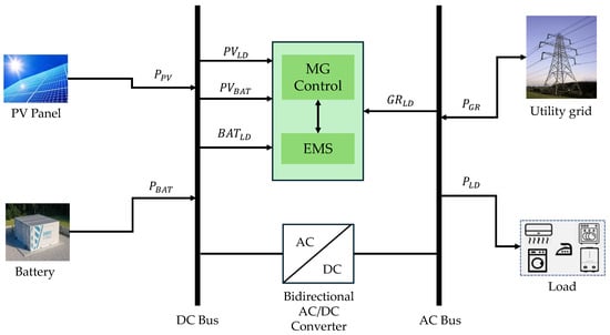
Figure 1.
The structure of the grid-connected MG system.
The parameters and constraints that govern the proposed system are presented in Table 1 along with their unit and mathematical label.

Table 1.
Parameters used in the analysis.
- Battery parameters: The battery capacity, , is set to 4500 mAh, equivalent to as follows:
- SOC: The initial SOC is , and its range is constrained to to prevent overcharging or deep discharge.
- SOH: The initial SOH is , with degradation calculated dynamically.
- Efficiency: The charging efficiency is 95%, and the discharging efficiency is 90%.
- Cost dynamics: The baseline electricity cost is 0.20 $/kWh. Peak-hour costs are doubled, and off-peak hours incur a discount factor of , as follows:
- Battery temperature: Ambient temperature is °C, and the critical temperature is °C.
3.2. Baseline Simulation of a Conventional EMS
The conventional system meets the load demand primarily from the grid, with support from PV generation . The battery contributes power as a last resort.
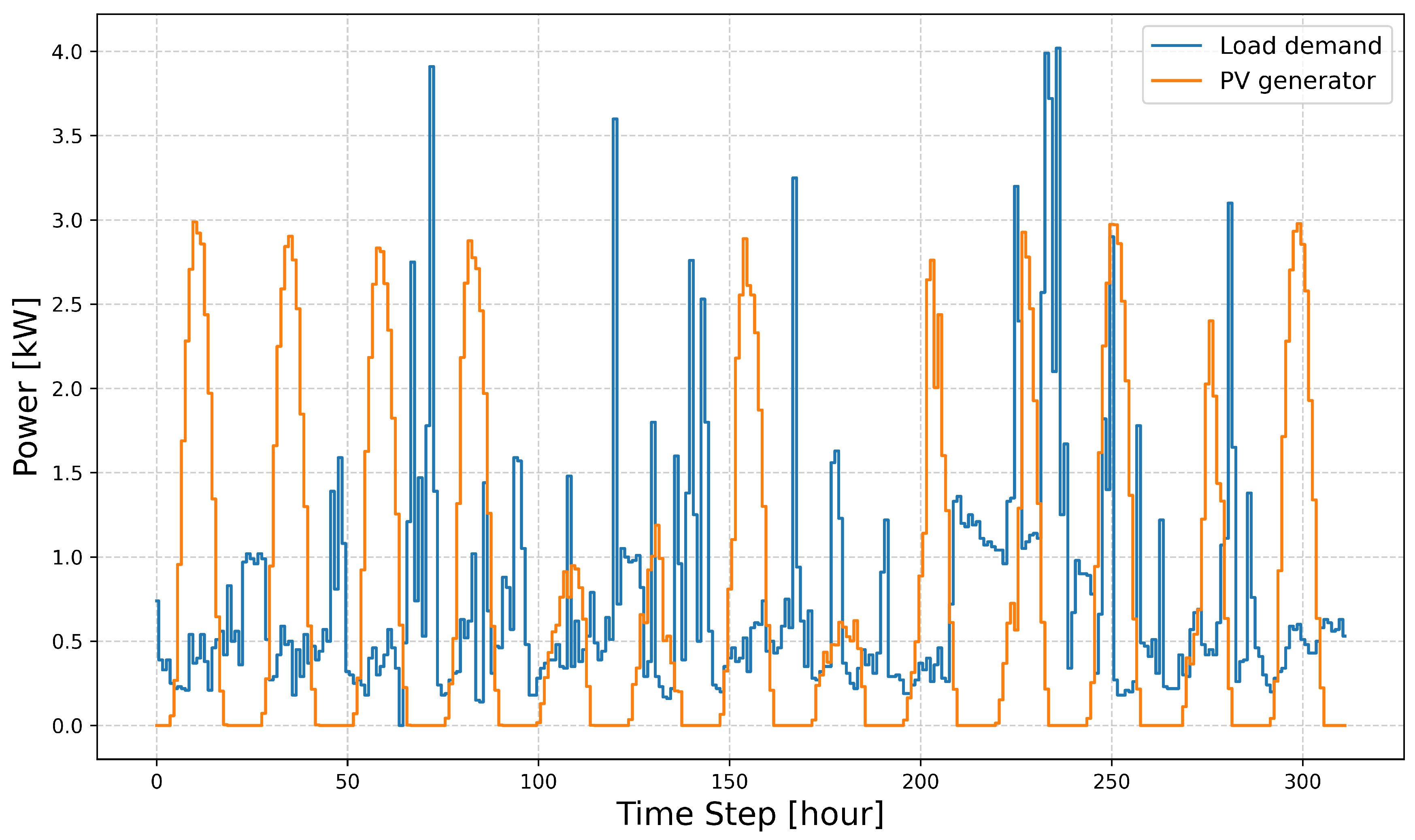
Figure 2 provides a detailed comparison between the and the over a series of hourly time steps. The load demand is represented by the blue line, while the PV generation is denoted by the orange line. Both time series show distinct patterns that reflect the dynamics of energy consumption and generation over time. The peaks at approximately 4.0 kW, indicating periods of high electricity usage and likely corresponding to high-activity hours in a residential or commercial environment. On the other hand, the achieves a maximum output of around 3.5 kW, which corresponds to times of peak solar irradiance, typically in the middle of the day. The load demand exhibits a cyclical pattern, with regular peaks and troughs, suggesting a typical daily consumption cycle. In contrast, PV generation only operates during daylight hours, with zero output during the night. At different intervals, the load demand exceeds the PV generation, such as between time steps 5–5 and
0–00, highlighting periods where additional energy sources, such as from batteries or drawing from the grid supply, are required to meet the excess demand. Conversely, during intervals, for example, for time steps 0 and 5, 5 and 0, the PV generation surpasses the load demand, indicating surplus energy that could be stored in batteries or fed back into the grid. This fluctuation demonstrates the importance of energy storage solutions for managing the mismatch between supply and demand.
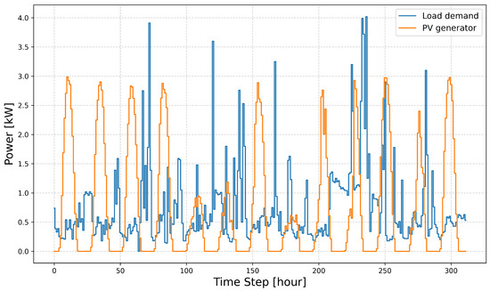
Figure 2.
Load demand and PV data for the grid-connected MG system.
3.2.1. Grid Power and Cost Calculation
The power drawn from the grid, , is calculated as follows:
The cost incurred for grid power during each time step is as follows:
where is obtained from Equation (2). The cumulative total cost is updated iteratively as follows:
where N is the total number of time steps in the interval.
3.2.2. SOC and Temperature Updates
The SOC at time step is updated based on the charging and discharging processes as follows:
where is the power allocated from PV to the battery, and is the power discharged from the battery to the load.
The battery temperature evolves dynamically with grid power usage as follows:
3.3. Real-Time EMS Using FLC
The FLC method uses fuzzy rules to adaptively manage energy flow based on SOC, load demand, battery temperature, and SOH.
3.3.1. Fuzzy Membership Function Design for SOC and SOH
Inputs are mapped to linguistic variables (e.g., “low”, “medium”, “high”) using triangular membership functions. For instance, SOC membership functions are defined as follows:
Outputs include the following:
- Charging priority (): Determines battery charging preference.
- Grid priority (): Determines reliance on grid power.
3.3.2. Fuzzy Rules and Decision-Making for Charging and Grid Reliance
Rules link fuzzy inputs to outputs, as follows:
- Rule 1: If SOC is “low” and load is “high”, then = “high” and = “high”.
- Rule 2: If SOC is “high” and temperature is “high”, then = “low”.
3.3.3. Optimisation for Energy Allocation
Fuzzy outputs are used to optimise energy flow using linear programming, as follows:
subject to the following:
System Constraints
The following constraints govern the operation of the conventional, FLC, and Deep-FLC systems:
- Load demand balance (Equation (11)): At each time step k, the total load demand is supplied through three sources, such as direct PV power to load (), import power from the grid (), and battery discharge power ().
- PV power distribution (Equation (12)): The total PV power is split into power directly supplied to the load () and power used to charge the battery ().
- SOC constraints (Equation (13)): The SOC of the battery at any time step k must remain within the operational range defined by and . For instance, in this study [5].
- SOH constraints (Equation (14)): The SOH of the battery must also be maintained within an acceptable range, to , ensuring the battery’s longevity and reliability. The acceptable range for the SOH is generally determined based on the specific application, battery type, and operational requirements and ensures the battery’s longevity and reliability while preventing excessive degradation.
Respecting these constraints ensures that the EMS operates within safe and efficient boundaries while optimising the distribution of power sources and protecting battery performance.
3.4. Deep-FLC: Integrating Prediction and Adaptation
Deep-FLC combines predictive modelling using LSTM networks with FLC. LSTM predicts SOC, load demand, and temperature, enabling proactive control.
3.4.1. LSTM-Based Forecasting of SOC, SOH, and Load Demand
The LSTM network predicts the SOC (), temperature (), and SOH () based on historical data. The prediction model is as follows:
where is the input sequence of past data.
3.4.2. Fuzzy Inputs from Predictions
Predictions from Equation (15) are fed into the fuzzy system, enabling dynamic adjustments to charge and grid priorities.
3.4.3. Dynamic Control
3.5. Performance Metrics for Comparing Energy Management Strategies
The systems are compared based on the following:
- Total cost: Computed using Equation (5).
- SOC stability: Range and variability of SOC over time.
- Battery efficiency: Ratio of energy used to total energy input.
- SOH degradation: Updated iteratively, as follows:where is the depth of discharge, as follows:
3.5.1. Depth of Discharge (DoD)
The DoD measures the use of the battery during each time step in hours, k and is calculated using Equation (17). A high average DoD indicates frequent battery usage, accelerating degradation, while lower values indicate minimal wear.
3.5.2. Battery Efficiency
Battery efficiency () is defined as the ratio of energy supplied by the battery to the total energy input, including charging losses. The efficiency is calculated as follows:
3.5.3. Cost Analysis
The total operational cost is evaluated for each system using Equation (5). The Deep-FLC system aims to minimise grid dependency while maximising the utilisation of RESs and battery storage.
3.5.4. SOH Degradation
The degradation of SOH is iteratively modelled using Equation (16), capturing the effects of DoD and elevated temperature as follows: and are the degradation rates due to DoD and the temperature exceeding ambient levels, respectively [25].
The final value of the SOH provides insight into the long-term sustainability of each energy management strategy.
3.6. Evaluation of Deep-FLC Model Performance
The predictive performance of the Deep-FLC model is assessed using the Mean Absolute Percentage Error (MAPE) and Root Mean Square Error (RMSE), which are normalised to ensure comparability across different scales.
3.6.1. Mean Absolute Percentage Error (MAPE)
The normalised MAPE is given by the following:
For the Deep-FLC model, the MAPE is as follows:
This indicates a moderate level of prediction accuracy, where a lower value suggests improved forecasting precision, while a value closer to 1 would imply higher deviation from actual values.
3.6.2. Root Mean Square Error (RMSE)
The normalised RMSE is expressed by the following:
For the Deep-FLC model, the RMSE is as follows:
This value suggests that the model maintains a stable level of error, ensuring effective energy management under dynamic conditions. With a normalised MAPE of 0.68, the Deep-FLC model demonstrates moderate prediction accuracy, meaning that while it effectively anticipates energy demand and resource variations, some deviations still exist due to the complexity of real-world energy patterns. A lower MAPE value would suggest near-perfect forecasting, whereas a value closer to 1 would indicate high error—thus, 0.68 represents a balanced trade-off between adaptability and accuracy. Similarly, the normalised RMSE of 0.74 reflects the overall deviation between predicted and actual values. This measure highlights how well the model maintains stable energy predictions under high-frequency variations in renewable power generation (e.g., wind and solar energy). An RMSE closer to 1 would indicate greater deviations, while a value near 0 would mean negligible errors. At 0.74, the model achieves a reasonable level of precision, ensuring that the battery and grid operations are optimised without excessive prediction errors.
3.7. Implementation Steps for the Deep-FLC Framework
Algorithm 1 in the context of energy management employs a systematic approach to optimise energy use, minimise operational costs, and prolong battery life in a residential energy system. The methodology begins with an initialisation and preprocessing stage, in which essential data, such as load demand, PV power, and battery metrics—including SOC, SOH and battery temperature—are prepared. Parameters, including the minimum and maximum SOC (Equation (13)) and SOH (Equation (14)) constraints, are defined to ensure the safe operation of the battery. Power flow restrictions are established to maintain the energy balance between PV power, battery power, and grid power, as expressed in Equations (11) and (12). This step provides the groundwork for the subsequent simulations by ensuring that all initial conditions are set appropriately and the dataset is adequately structured.
The first simulation phase focuses on the conventional system, which allocates energy using conventional methods without advanced control techniques. Linear programming is applied to optimise grid power usage and battery discharging based on cost considerations. At each time step, the SOC is updated using a dynamic relationship between charging and discharging power, as defined in Equation (6), while ensuring SOC values remain constrained within the prescribed constraints to avoid overcharging or excessive discharge. Likewise, battery temperature is updated based on grid power usage, following the relationship specified in Equation (7). Safeguards are implemented to ensure that the temperature does not exceed the critical threshold, which is typically specified by the battery manufacturer to protect against thermal stress and ensure safe operation. This baseline simulation serves as a benchmark for evaluating the performance of more advanced control systems.
| Algorithm 1 Energy management using Deep-FLC | |
| 1: | Input: , , Battery (), and Cost Parameters, N |
| 2: | Output: Optimal Grid Power , Battery Usage , and PV Distribution |
| 3: | Step 1: Initialisation and preprocessing |
| 4: | Load dataset and preprocess , , , |
| 5: | Set constraints: , , , , and |
| 6: | Step 2: Conventional system simulation |
| 7: | for do |
| 8: | |
| 9: | |
| 10: | Clamp within |
| 11: | |
| 12: | end for |
| 13: | Step 3: FLC simulation |
| 14: | Define fuzzy inputs: SOC, SOH, Load, Temperature |
| 15: | Define fuzzy outputs: Charging Priority and Grid Priority |
| 16: | Construct fuzzy membership functions and rules |
| 17: | for do |
| 18: | Compute fuzzy outputs: Charging Priority, Grid Priority |
| 19: | Solve |
| 20: | Update and |
| 21: | end for |
| 22: | Step 4: Deep-FLC simulation |
| 23: | Train LSTM model on historical data: SOC, SOH, and |
| 24: | for do |
| 25: | Predict using LSTM |
| 26: | Compute fuzzy logic outputs with predicted values |
| 27: | Solve |
| 28: | Update and |
| 29: | end for |
| 30: | Step 5: Evaluate systems |
| 31: | Calculate metrics: Total cost, Battery efficiency, Average DoD, Final SOC and SOH |
| 32: | Compare conventional, FLC, and Deep-FLC systems |
| 33: | return Results |
The second phase incorporates a FLC system, which adopts a rule-based methodology to manage energy flow dynamically. The fuzzy logic controller processes inputs such as SOC, SOH, battery temperature, and load demand, producing outputs such as charging priority () and grid priority (). Membership functions, defined for variables such as SOC (“low”, “medium”, “high”), enable the system to respond adaptively to varying operating conditions. For instance, when SOC is low, load demand is high, and SOH is deteriorating, the fuzzy system increases and to meet the load demand while preserving battery health. Energy allocation decisions are subsequently optimised using linear programming, with fuzzy logic outputs guiding the process. As with the conventional system, SOC and battery temperature are updated at each time step, but the FLC system adds the advantage of prioritisation based on real-time conditions.
The final phase integrates fuzzy logic with predictive modelling via Deep-FLC. This hybrid approach uses a LSTM neural network trained on historical data to forecast future SOC, SOH, and battery temperature. These predictions allow the fuzzy logic system to operate with foresight, dynamically adjusting priorities to optimise costs and battery use over time. At each time step, the LSTM model generates predictions (, , and ) based on a sequence of prior states (Equation (15)), which are then fed into the fuzzy logic system as inputs. By incorporating predictive modelling, Deep-FLC achieves better anticipation of future energy demands, thereby reducing grid reliance during peak hours, minimising DoD, and prolonging battery life.
The optimisation in Deep-FLC employs linear programming, which dynamically incorporates the fuzzy logic outputs while adhering to constraints derived from power flow and battery constraints (Equation (9)). These constraints ensure that the Deep-FLC effectively balances the trade-offs between grid power usage, battery charging/discharging, and cost efficiency. The algorithm’s efficacy is evaluated by comparing the three systems—conventional, FLC, and Deep-FLC—based on total cost, battery efficiency, average DoD, and final SOC and SOH values. The results are presented in the next section.
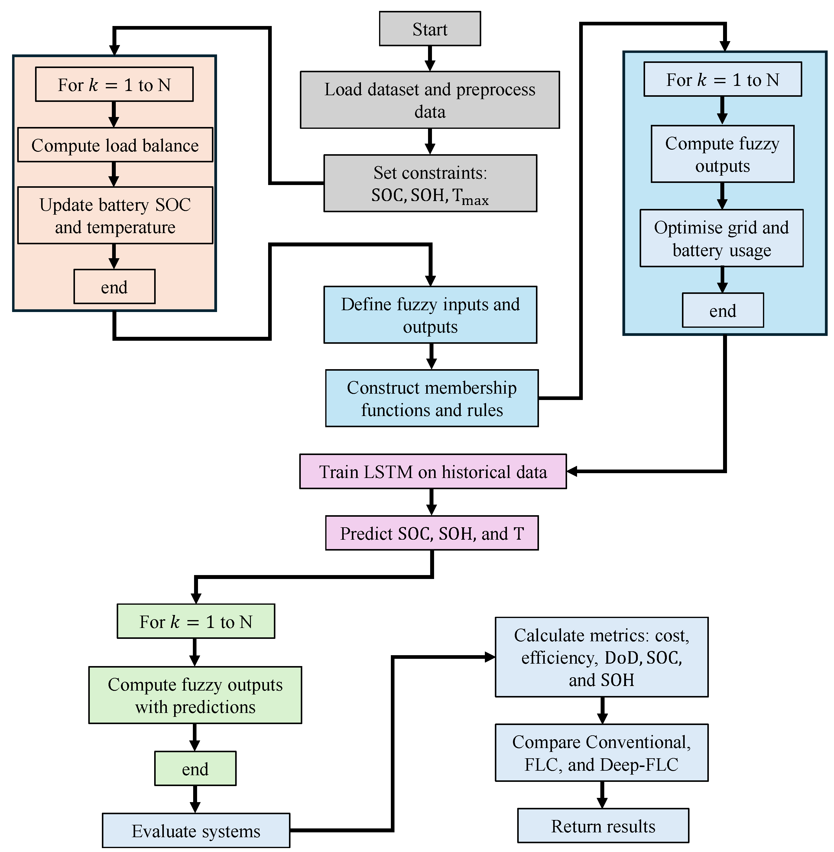
The flowchart in Figure 3 outlines the Deep-FLC-based energy management system, illustrating the step-by-step computational process of optimising energy allocation in a grid-connected MG. The framework integrates FLC and LSTM networks, enabling adaptive and predictive decision making for optimal battery and grid power management.
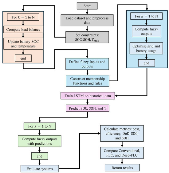
Figure 3.
Flowchart of the proposed method.
The process begins with data loading and preprocessing, collecting historical and real-time data related to load demand, renewable energy generation, and battery status. The system establishes operational constraints, including SOC constraints, SOH thresholds, and critical temperature conditions, to ensure safe battery operation.
The next phase involves the conventional energy management process, where, over a specified time horizon (k = 1 to N), the system continuously computes the load balance and updates the battery SOC and temperature based on energy flow conditions. This represents the traditional EMS approach, which lacks adaptability to unpredictable energy supply and demand variations.
To improve adaptability, the framework then transitions to fuzzy logic-based control. This phase begins with defining fuzzy inputs and outputs, where key parameters such as SOC, SOH, load demand, and temperature are assigned fuzzy membership values. The system constructs fuzzy membership functions and rules, which enable real-time decision making regarding charging priorities and grid reliance. The fuzzy logic controller operates iteratively over k = 1 to N, dynamically computing fuzzy outputs and optimising grid and battery usage. The predictive capability of Deep-FLC is introduced through LSTM-based forecasting. The system is trained on historical MG data, learning patterns in SOC fluctuations, SOH degradation, and temperature variations. Once trained, the LSTM model predicts future SOC, SOH, and temperature conditions, providing a foresight mechanism that enhances energy management decisions.
In the final control phase, the predicted values from LSTM are incorporated into the fuzzy logic controller, allowing the system to compute fuzzy outputs dynamically based on anticipated future conditions rather than only reacting to real-time inputs. This approach ensures proactive energy management, reducing unnecessary battery cycling, minimising grid dependency, and enhancing battery lifespan. The last stage involves evaluating system performance, where key performance metrics such as total cost, energy efficiency, DoD, final SOC, and SOH degradation are calculated. The results from the conventional EMS, FLC, and Deep-FLC are compared to validate the improvements offered by the proposed approach. The optimised results are then returned as the final output.
4. Results
This section presents the outcomes of the simulations, highlighting the advantages of the Deep-FLC system over the conventional and FLC-based approaches. Key performance metrics, including SOC stability, grid dependency, DoD, SOH preservation, and cost efficiency, are analysed and compared. The results demonstrate how integrating predictive modelling with adaptive control significantly enhances energy management performance.
4.1. Improved SOC Stability with Deep-FLC Compared to Baselines
The upper panels of Figure 4 illustrate the SOC trends for the conventional system, FLC, and Deep-FLC, respectively.
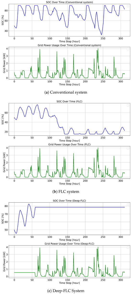
Figure 4.
The comparison of SOC of the battery and imported energy from the grid in conventional, FLC, and Deep-FLC systems.
- Conventional system: The SOC fluctuates significantly, varying between 40% and 90%, with frequent falls below 50%, as illustrated in Figure 4a. These fluctuations highlight inefficiencies in charging and discharging, leading to suboptimal battery usage.
- FLC system: SOC variability is reduced compared to the conventional system, generally ranging between 40% and 60%, see Figure 4b. However, SOC occasionally falls below 40%, which could lead to increased battery stress and a reduced lifespan.
- Deep-FLC system: After the initial increase during the first 50 time steps, the SOC is maintained with exceptional stability at around 80%, as shown in Figure 4c. This consistency indicates that Deep-FLC manages energy flow more effectively, ensuring the battery operates within its optimal charge range.
4.1.1. Clarification of the Optimisation Function
The optimisation function employed within the Deep-FLC framework balances grid dependency, battery efficiency, and operational costs while ensuring system stability. The objective function minimises the total cost of energy consumption by dynamically adjusting charging and discharging priorities, incorporating the following constraints:
where the following holds:
- represents the degree to which grid power is prioritised.
- dictates battery charging preferences based on the SOC, SOH, and anticipated load demand.
The function ensures that SOC levels remain within safe operational limits , avoiding excessive DoD while prioritising renewable energy utilisation. The effectiveness of this function is further validated through comparative performance analysis against conventional and fuzzy logic-based energy management strategies.
4.1.2. Simulation Validation and Robustness
To validate the performance of Deep-FLC, extensive simulations were conducted using real-world energy consumption patterns and PV generation datasets. The validation steps include the following:
- Benchmarking against established methods: The Deep-FLC framework was compared with both conventional rule-based and fuzzy logic control systems under identical operational conditions. This comparative approach highlights improved grid independence, cost efficiency, and battery longevity.
- Sensitivity analysis: Parameter sensitivity analysis was performed to examine how variations in SOC thresholds, load demand fluctuations, and renewable generation uncertainty affect system performance. Results indicate that Deep-FLC consistently maintains stable SOC levels and reduces battery stress.
- Error metrics for predictive accuracy: The predictive modelling component, implemented using LSTM networks, was evaluated using MAPE and RMSE. The MAPE value of 0.68 and RMSE value of 0.74 demonstrate a strong forecasting capability, supporting the proactive energy management approach.
- SOC stability: Unlike the conventional and FLC systems, which exhibit significant fluctuations in SOC levels, the Deep-FLC framework maintains SOC stability within an optimal operational range. This ensures improved battery health and extends lifespan.
- Grid dependency reduction: The Deep-FLC system demonstrates a smoother and more controlled reliance on grid power, particularly during peak demand periods, due to its predictive capability and adaptive control strategy.
- Charging and discharging cycles: The optimised fuzzy control mechanism, in conjunction with the LSTM-based predictions, allows the system to proactively schedule battery operations, thereby reducing unnecessary deep discharges and minimising energy losses.
4.2. Reduction in Grid Dependency Through Optimised Battery Use
The grid power usage trends for the three systems are presented in the lower panels of Figure 4 with the following parameters:
- Conventional system: Grid power use is highly variable, with frequent spikes exceeding 3.5 kW, see Figure 4a. The heavy reliance on the grid during peak hours is evident and reflects inefficiencies in energy management and a lack of proactive storage utilisation.
- FLC system: Figure 4b demonstrates reduced peaks in grid power use compared to the conventional system, although occasional spikes still reach 3.5 kW. However, variability remains, indicating there is room for improvement in balancing grid dependency.
- Deep-FLC system: Figure 4c shows that grid power use is significantly smoother, with peaks rarely exceeding 4.0 kW. The reliance on the grid is minimised during high-demand periods, illustrating the system’s ability to maximise renewable energy utilisation and battery storage.
4.3. Minimisation of DoD to Extend Battery Lifespan
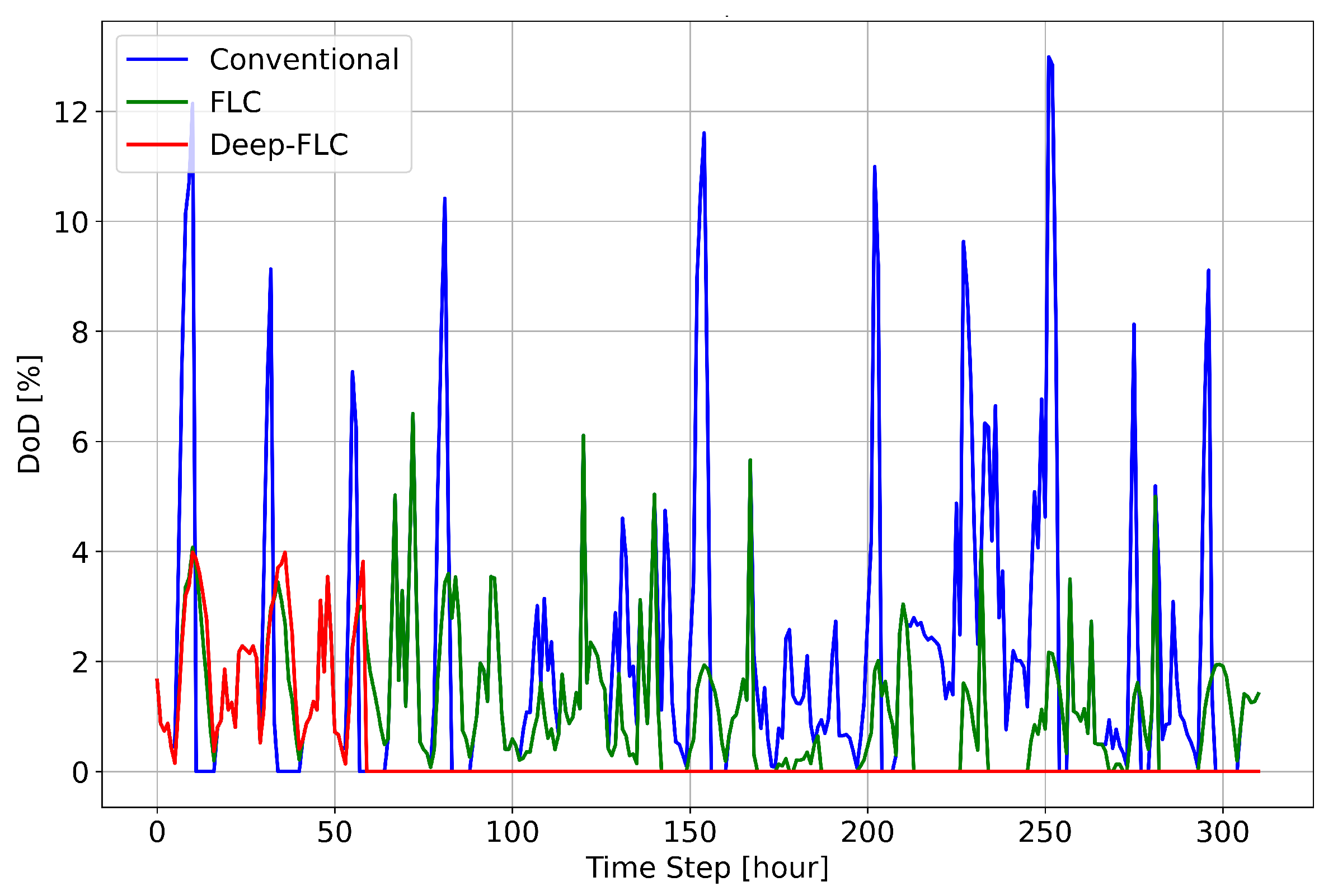
A comprehensive comparison of the DoD across the different EMSs is provided in Figure 5), and the following observations highlight the performance of the conventional, FLC, and Deep-FLC systems in terms of battery stress and overall stability:
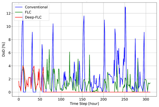
Figure 5.
The comparison of DoD of the battery in conventional, FLC, and Deep-FLC systems.
- Conventional system: DoD fluctuates significantly, with spikes often exceeding 10% per time step, for example, at steps 0, 0, 55, and 50, contributing to high battery stress.
- FLC system: DoD is reduced to below 4% per time step, but occasional larger discharges above 5% still occur, such as at steps 5, 20, and 70. Interestingly, the spikes occur at different steps compared to the conventional system.
- Deep-FLC system: DoD consistently remains below 4% per time step; throughout the monitored period and beyond 50 steps, the DoD is close to 0%. As a result, the battery street is minimised, enhancing longevity.
4.4. Superior SOH Preservation Under Deep-FLC
The SOH of the battery is a critical metric for assessing long-term sustainability and performance across different EMSs. The following summarises the SOH performance for the conventional, FLC, and Deep-FLC systems over a 300-h simulation period, as illustrated in Figure 6:
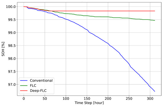
Figure 6.
The comparison of the SOH of the battery in conventional, FLC and Deep-FLC systems.
- Conventional system: SOH falls from 100% with systematically increasing slope to below 97% over 300 simulation steps due to frequent deep discharges and large SOC fluctuations.
- FLC system: Whilst initially moderate degradation due to occasional deep discharges, SOH retention improves, reaching approximately 99.3% after 300 steps.
- Deep-FLC system: SOH performed statistically in a similar manner to the FLC up to about 60 simulation steps; however, beyond that, SOH remained above 99.8%, reflecting minimal degradation due to stable SOC management and reduced DoD.
4.5. Cost and Energy Efficiency Improvements in Deep-FLC
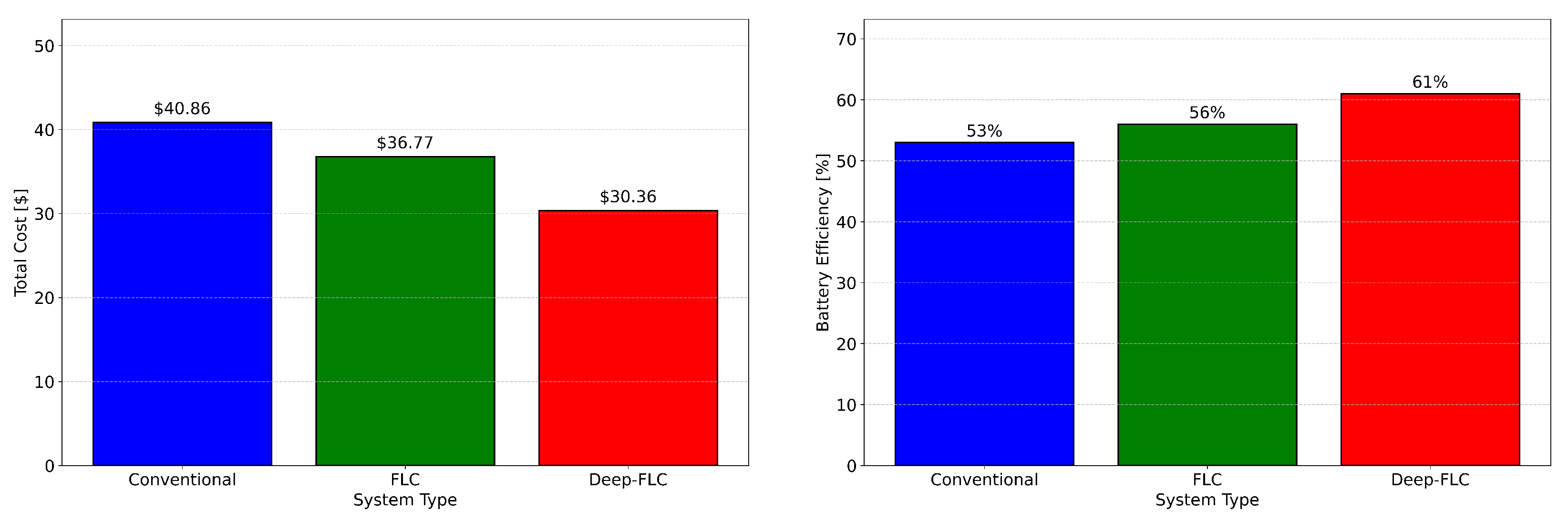
Consistent with previous research [41], the total operational costs of the conventional, FLC, and Deep-FLC systems are used in this study to reveal the economic benefits of advanced energy management strategies. Figure 7 (left) illustrates the total operational costs for each system. The conventional system incurs the highest cost of $40.86 due to its frequent reliance on grid power, particularly during peak hours. In contrast, the FLC system reduces costs to $36.77, representing a 10% savings compared to the conventional system. However, the most significant cost reduction is achieved with the Deep-FLC system, which incurs a total cost of $30.36. This represents a 25.7% saving compared to the conventional system and a 17.5% improvement over the FLC system, highlighting the economic benefits of adopting the advanced Deep-FLC strategy.

Figure 7.
Comparison of total cost (left) and battery efficiency (right) during conventional, FLC, and Deep-FLC systems.
Figure 7 (right) highlights the battery efficiency across the three management systems. The conventional system, achieving only 53%, exhibits the lowest efficiency due to significant energy losses and inefficient grid-battery interaction. The FLC system demonstrates a moderate improvement in energy utilisation, improving battery efficiency to a level of 56%. On the other hand, the Deep-FLC system achieves the highest battery efficiency and, at a level of 61%, reflects its ability to minimise energy losses and optimise power flow between the grid, battery, and load. These findings demonstrate and underscore the effectiveness of the Deep-FLC system, not only in reducing operational costs but also in enhancing battery efficiency, thereby contributing to both economic and energy performance improvements.
4.6. Dynamic Charging Priority Adjustments for Real-Time Optimisation
The dynamic charging priority, as observed in Figure 8, showcases the highly adaptive and intelligent behaviour of the Deep-FLC system. Charging priority fluctuates smoothly within a controlled range of approximately 16.67–16.73%, reflecting the system’s ability to respond effectively to real-time conditions guided by LSTM predictions. While this numerical range appears small, the graph visually indicates the flexibility and responsiveness of the system. The relevance lies in the system’s ability to make finely resolved adjustments while maintaining overall stability. During periods of low SOC or high load demand, the system strategically reduces the charging priority to alleviate stress on the grid and ensure operational stability. Conversely, under favourable conditions, such as a moderate load demand or higher SOC, the system increases charging priority, enabling efficient battery charging while maintaining grid balance. These fluctuations indicate a delicate balance between energy supply, demand, and grid reliance.
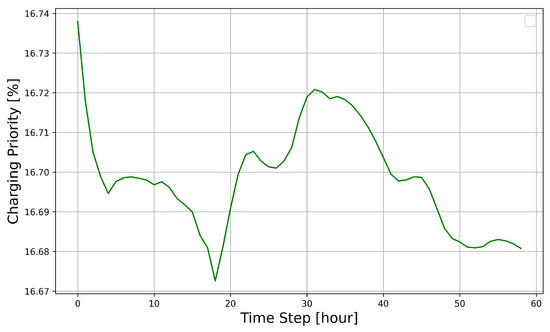
Figure 8.
Dynamic charging priority based on Deep-FLC predictions.
5. Discussion
In this section, the results presented in the previous section are consolidated and discussed in greater detail. Explanations of how the Deep-FLC framework outperforms other energy management approaches are provided, supported by insights from previous research studies. Table 2 serves as a summary of the performance metrics for the conventional, FLC, and Deep-FLC systems. These results form the basis for the detailed discussion that follows, where the implications of each performance metric are explored in the context of cost, battery efficiency, and longevity.
Table 2.
Comparison of conventional, FLC, and Deep-FLC systems.
While the FLC system demonstrates improvements over the conventional system, it is limited by its lack of predictive capabilities and dynamic adjustments. The Deep-FLC system addresses these limitations by integrating predictive modelling and adaptive control, offering foresight and flexibility in managing energy flow. This integration not only reduces operational costs but also minimises the environmental impact by decreasing grid reliance and maximising the utilisation of RESs.
5.1. Cost Reduction Achieved Through Predictive Energy Control
As shown in Figure 7 (right), the cost savings of the Deep-FLC over the conventional system (25.7%) and FLC system (17.5%) are primarily attributed to the system’s ability to minimise reliance on grid electricity, particularly during peak hours. This is achieved by prioritising battery usage and renewable energy storage 24/7, thereby reducing grid dependency during high-cost energy periods while still ensuring sufficient power delivery to meet demand. In contrast, the higher cost benefits delivered over the conventional system stem from its heavy reliance on grid power, leading to significantly higher operational costs. The lower cost benefit over the FLC system reflects the latter’s moderate improvements in energy management. However, the FLC system lacks the granularity in decision making and predictive capability offered by Deep-FLC, which enables the real-time optimisation of energy allocation to maximise cost savings.
5.2. Enhancing SOC Stability and Maximising Battery Efficiency in EMSs
The Deep-FLC system demonstrates superior SOC stability compared to the conventional and FLC systems, as shown in Figure 4. By maintaining the SOC consistently around 80%, the Deep-FLC system avoids both deep discharges (<40%) and overcharging (>90%), which are detrimental to battery health. This stability directly contributes to improved energy efficiency and reduced battery degradation in Figure 4c.
These benefits are primarily due to the integration of predictive modelling (via LSTM) and adaptive fuzzy control, which allow Deep-FLC to anticipate energy demands and adjust charging and discharging priorities dynamically. Unlike static or purely adaptive systems, Deep-FLC combines foresight with real-time adaptability, ensuring that the battery operates within its optimal SOC range.
In contrast, the conventional system relies on predefined thresholds for charging and discharging, resulting in significant SOC fluctuations between 40% and 90% (Figure 4a). These fluctuations stem from its inability to respond to dynamic energy demands and supply variations, leading to inefficient battery utilisation. Similarly, the FLC system, while more adaptive than the conventional system, lacks predictive capabilities, causing occasional SOC drops below 40% (Figure 4b). Such deep discharges are a known cause of accelerated battery degradation, as highlighted in previous studies [25].
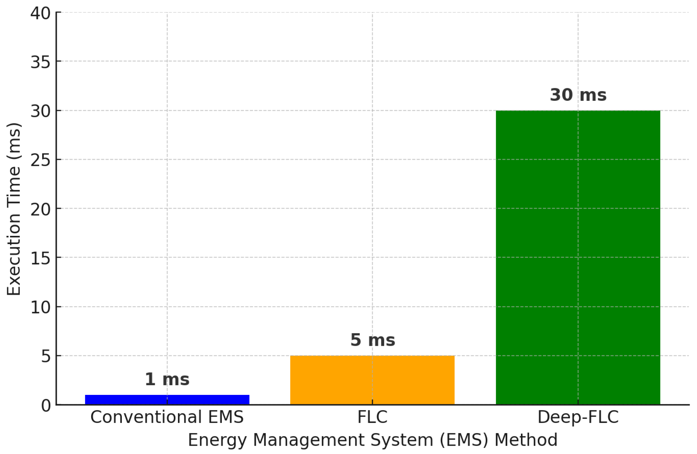
5.3. The Computational Time Comparison of EMS Methods
The computational time is a crucial factor in determining the feasibility of implementing these systems in real-time applications, particularly in microgrid and renewable energy management. As illustrated in Figure 9, the conventional EMS exhibits the lowest computational time, approximately 1 millisecond, as it primarily relies on predefined rule-based decision making. This method is computationally efficient, but it lacks adaptability to dynamic variations in energy supply and demand.

Figure 9.
Computational time comparison of three strategies.
In contrast, the FLC-based EMS incurs a slightly higher computational burden, with an execution time of around 5 milliseconds. This increase is attributed to the real-time fuzzy inference system, which dynamically evaluates multiple input parameters, including SOC, battery health, and grid energy demand. Although this approach introduces a degree of adaptability, it remains fundamentally reactive, as it does not incorporate predictive capabilities. The Deep-FLC approach, which integrates LSTM-based forecasting with FLC, presents the highest computational time, approximately 30 milliseconds. This additional complexity stems from the predictive nature of LSTM models, which analyse historical energy data to anticipate future energy demand and battery behaviour. Despite the increase in computational load, the 30-millisecond execution time remains well within acceptable limits for microgrid energy management, which typically operates on longer timescales of minutes or even hours. Thus, the Deep-FLC method remains a viable and scalable solution for industrial applications where predictive control is essential for enhancing battery longevity, reducing operational costs, and improving grid stability.
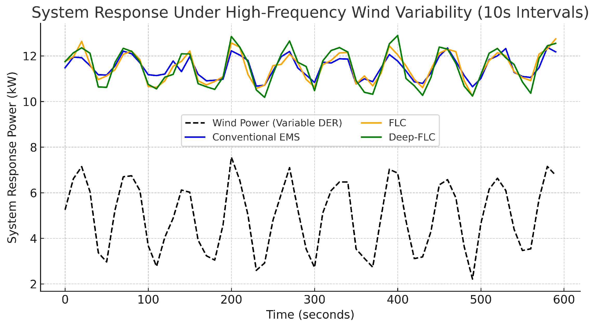
5.4. System Response Under High-Frequency Wind Variability
Figure 10 represents the wind power variations, demonstrating the inherent instability in wind energy generation due to unpredictable changes in wind speed. The conventional EMS (blue line) exhibits a sluggish response, struggling to effectively adapt to these rapid fluctuations, which could result in inefficient energy distribution and higher reliance on grid power.
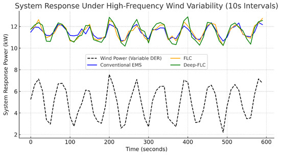
Figure 10.
System response under high-frequency wind variability for three different strategies.
The FLC-based EMS (orange line) shows an improved response, as it dynamically adjusts energy distribution based on real-time fuzzy logic inference. However, it remains reactive rather than predictive, leading to occasional mismatches in power adjustment. In contrast, the Deep-FLC system (green line) exhibits the most adaptive and stable response, closely following wind power variations while ensuring optimised battery and grid usage. By integrating LSTM-based forecasting, the Deep-FLC method proactively anticipates energy demand and adjusts control actions accordingly, thereby minimising fluctuations and enhancing system stability. The results clearly indicate that Deep-FLC significantly outperforms both conventional and FLC-based EMS approaches, making it an effective solution for real-time MG energy management in variable renewable energy conditions.
5.5. Optimising Battery Efficiency Through Adaptive Charging and Discharging Cycles
The battery efficiency results, illustrated in Figure 7 (right), further demonstrate and underscore the advantages of the Deep-FLC system. Achieving an efficiency of 61%, Deep-FLC outperforms the conventional system (53%) and the FLC system (56%) by optimising charging and discharging cycles. At this level of efficiency, Deep-FLC achieves a significant improvement over both systems by maintaining SOC stability, minimising DoD, and avoiding overcharging or deep discharges.
How Deep-FLC Achieves Higher Efficiency
- SOC stability: The Deep-FLC system leverages predictive modelling (via LSTM) to forecast energy demand and renewable energy availability. This foresight enables the system to pre-emptively adjust battery charging and discharging operations, maintaining the SOC within its optimal range (e.g., 40–90%). This approach reduces energy losses associated with overcharging and deep discharges, which are more prevalent in the conventional and FLC systems due to their reactive strategies.
- Minimised Depth of Discharge (DoD): By keeping DoD consistently below 2%, Deep-FLC reduces the cumulative stress on the battery during discharging cycles. Research shows that lower DoD values lead to higher energy utilisation efficiency and slower degradation of battery capacity [25]. In contrast, larger DoD fluctuations in the conventional and FLC systems result in greater energy losses during charge/discharge cycles.
5.6. Minimising DoD and Preserving Battery SOH Through Proactive Energy Management
The stability of the SOC and minimisation of the DoD, as evidenced in Figure 5, directly impact the battery’s long-term health. The Deep-FLC system constraints the DoD to below 2% per time step, significantly reducing the cumulative stress on the battery compared to the conventional system, where the DoD frequently exceeds 10%, and the FLC system, which reduces DoD variability but still allows occasional spikes slightly over 6%. This improved discharge regulation directly translates to reduced battery wear and extended operational lifespan. The impact of these improvements is evident in the SOH trends shown in Figure 6. Over the 300-h simulation, the conventional system experiences a sharp SOH decline, dropping from 100% to below 97%, due to frequent deep discharges and high DoD. The FLC system slows this degradation, maintaining a SOH at 99.3%, but still allowing for moderate wear due to occasional inefficiencies in energy management. The Deep-FLC system exhibits near-zero degradation, with the SOH remaining above 99.8% throughout the simulation, showcasing its ability to preserve battery health through a stable SOC and controlled discharge cycles.
5.7. Adaptive Charging Priority Adjustments Using LSTM Predictions for Enhanced Energy Flow Management
The effectiveness of the Deep-FLC system is further highlighted in Figure 8, which illustrates the dynamic charging priority over time. The charging priority varies smoothly within a narrow range (16.67–16.73%), reflecting fine-tuned adjustments to system demands based on LSTM-predicted future states. By dynamically lowering charging priority during periods of high load or low SOC, the system prevents unnecessary grid dependency and mitigates battery stress. The subsequent recovery of charging priority demonstrates the system’s ability to adapt and optimise energy flow in real time. This dynamic behaviour is a key differentiator of Deep-FLC, as it ensures efficient energy allocation while maintaining system stability, unlike the static behaviour observed in the conventional and FLC systems.
6. Conclusions
The findings of this study establish Deep-FLC as a transformative energy management solution for renewable-integrated systems. By integrating predictive modelling through LSTM networks with adaptive fuzzy logic, Deep-FLC effectively addresses the limitations of traditional energy management methods. Deep-FLC combines the foresight provided by predictive analytics with the real-time adaptability of fuzzy control, creating a system that dynamically optimises energy flow while preserving battery health. The results demonstrate that Deep-FLC outperforms both the conventional and FLC systems in all key metrics. Deep-FLC achieves a substantial reduction in operational costs, with a 25.7% saving compared to the conventional system and a 17.5% saving over FLC, resulting in the lowest total cost of $30.36. Additionally, Deep-FLC achieves the highest battery efficiency of 61%, surpassing the 53% efficiency of the conventional system and the 56% achieved by the FLC. This improved efficiency is directly linked to Deep-FLC’s ability to optimise battery charging and discharging cycles while minimising energy losses. Deep-FLC also excels in maintaining battery health and extending battery lifespan. By keeping the DoD below 2% per time step and ensuring SOC stability within the optimal range of 78–82%, the system significantly reduces battery stress. Consequently, the SOH degradation is limited to less than 0.2% over 300 h, compared to a steep decline to 97% in the conventional system. These results highlight the long-term benefits of Deep-FLC in reducing battery wear and replacement costs. Furthermore, introducing dynamic charging priority in Deep-FLC enables fine-tuned adjustments based on LSTM-predicted SOC, load demand, and battery health. This ensures the system maintains optimal energy allocation while minimising reliance on expensive grid electricity during peak hours. Unlike the conventional and FLC systems, which operate reactively, Deep-FLC anticipates system conditions and adapts proactively, resulting in smoother grid usage and improved system stability.
Author Contributions
Conceptualization, M.C., D.D. and M.B.; methodology, M.C.; software, M.C.; validation, M.C., D.D. and M.B.; investigation, M.C.; resources, M.C.; writing—original draft preparation, M.C.; writing—review and editing, M.C., D.D. and M.B.; visualization, M.C. All authors have read and agreed to the published version of the manuscript.
Funding
This research received no external funding.
Data Availability Statement
The data and code related to this study have been published publicly in the GitHub repository at https://github.com/cavusmuhammed68/Deep_FLC. accessed on 25 January 2025.
Conflicts of Interest
The authors declare no conflicts of interest.
References
- Zhang, S.; Ocłoń, P.; Klemeš, J.J.; Michorczyk, P.; Pielichowska, K.; Pielichowski, K. Renewable energy systems for building heating, cooling and electricity production with thermal energy storage. Renew. Sustain. Energy Rev. 2022, 165, 112560. [Google Scholar] [CrossRef]
- Chowdhury, N.R.; Belikov, J.; Beck, Y.; Levron, Y.; Baimel, D. The role of storage degradation in energy management problems: An optimal control perspective. J. Energy Storage 2023, 67, 107412. [Google Scholar] [CrossRef]
- Ali, M.; Prakash, K.; Hossain, M.A.; Pota, H.R. Intelligent energy management: Evolving developments, current challenges, and research directions for sustainable future. J. Clean. Prod. 2021, 314, 127904. [Google Scholar] [CrossRef]
- Abdalla, A.N.; Nazir, M.S.; Tao, H.; Cao, S.; Ji, R.; Jiang, M.; Yao, L. Integration of energy storage system and renewable energy sources based on artificial intelligence: An overview. J. Energy Storage 2021, 40, 102811. [Google Scholar] [CrossRef]
- Cavus, M.; Allahham, A.; Adhikari, K.; Zangiabadi, M.; Giaouris, D. Energy management of grid-connected microgrids using an optimal systems approach. IEEE Access 2023, 11, 9907–9919. [Google Scholar] [CrossRef]
- Bird, L.; Milligan, M.; Lew, D. Integrating Variable Renewable Energy: Challenges and Solutions; National Renewable Energy Lab (NREL): Golden, CO, USA, 2013. [Google Scholar]
- Song, H.; Liu, C.; Amani, A.M.; Gu, M.; Jalili, M.; Meegahapola, L.; Yu, X.; Dickeson, G. Smart optimization in battery energy storage systems: An overview. Energy AI 2024, 17, 100378. [Google Scholar] [CrossRef]
- Klausmann, F.; Klingler, A.-L. Adaptive control strategy for stationary electric battery storage systems with reliable peak load limitation at maximum self-consumption of locally generated energy. Energies 2023, 16, 3964. [Google Scholar] [CrossRef]
- Suganthi, L.; Iniyan, S.; Samuel, A.A. Applications of fuzzy logic in renewable energy systems–a review. Renew. Sustain. Energy Rev. 2015, 48, 585–607. [Google Scholar] [CrossRef]
- Ibrahim, O.; Bakare, M.S.; Amosa, T.I.; Otuoze, A.O.; Owonikoko, W.O.; Ali, E.M.; Adesina, L.M.; Ogunbiyi, O. Development of fuzzy logic-based demand-side energy management system for hybrid energy sources. Energy Convers. Manag. X 2023, 18, 100354. [Google Scholar] [CrossRef]
- El Zerk, A.; Ouassaid, M. Real-time fuzzy logic-based energy management system for microgrid using hardware in the loop. Energies 2023, 16, 2244. [Google Scholar] [CrossRef]
- Emrani, A.; Achour, Y.; Sanjari, M.J.; Berrada, A. Adaptive energy management strategy for optimal integration of wind/PV system with hybrid gravity/battery energy storage using forecast models. J. Energy Storage 2024, 96, 112613. [Google Scholar] [CrossRef]
- Harrou, F.; Kadri, F.; Sun, Y. Forecasting of photovoltaic solar power production using LSTM approach. Adv. Stat. Model. Forecast. Fault Detect. Renew. Energy Syst. 2020, 3, 1–16. [Google Scholar]
- Wen, X.; Liao, J.; Niu, Q.; Shen, N.; Bao, Y. Deep learning-driven hybrid model for short-term load forecasting and smart grid information management. Sci. Rep. 2024, 14, 13720. [Google Scholar] [CrossRef]
- Pushpavalli, M.; Dhanya, D.; Kulkarni, M.; Rajitha Jasmine, R.; Umarani, B.; RamprasadReddy, M.; Garapati, D.P.; Yadav, A.S.; Rajaram, A. Enhancing electrical power demand prediction using LSTM-based deep learning models for local energy communities. Electr. Power Components Syst. 2024, 1–18. [Google Scholar] [CrossRef]
- Alzoubi, A. Machine learning for intelligent energy consumption in smart homes. Int. J. Comput. Inf. Manuf. 2022, 2, 62–75. [Google Scholar] [CrossRef]
- Cavus, M.; Allahham, A. Enhanced microgrid control through genetic predictive control: Integrating genetic algorithms with model predictive control for improved non-linearity and non-convexity handling. Energies 2024, 17, 4458. [Google Scholar] [CrossRef]
- Lipu, M.S.H.; Mamun, A.A.; Ansari, S.; Miah, M.S.; Hasan, K.; Meraj, S.T.; Abdolrasol, M.G.M.; Rahman, T.; Maruf, M.H.; Sarker, M.R. Battery management, key technologies, methods, issues, and future trends of electric vehicles: A pathway toward achieving sustainable development goals. Batteries 2022, 8, 119. [Google Scholar] [CrossRef]
- Wang, B.; Wu, Z.; Hou, X.; Cheng, Y.; Guo, T.; Xiao, H.; Ren, J.; Mansor, M.R.A. Fuzzy logic optimized threshold-based energy management strategy for fuel cell hybrid E-bike. Int. J. Hydrog. Energy 2024, 63, 123–132. [Google Scholar] [CrossRef]
- DeSando, M. Universal Programmable Battery Charger with Optional Battery Management System. Master’s Thesis, California Polytechnic State University, San Luis Obispo, CA, USA, 2015. Available online: https://digitalcommons.calpoly.edu/theses/1409/ (accessed on 13 January 2025).
- Fan, C.; Lu, M.; Sun, Y.; Liang, D. A novel linear programming-based predictive control method for building battery operations with reduced cost and enhanced computational efficiency. Renew. Energy 2024, 237, 121847. [Google Scholar] [CrossRef]
- Cavus, M.; Allahham, A.; Adhikari, K.; Giaouris, D. A hybrid method based on logic predictive controller for flexible hybrid microgrid with plug-and-play capabilities. Appl. Energy 2024, 359, 122752. [Google Scholar] [CrossRef]
- Impram, S.; Nese, S.V.; Oral, B. Challenges of renewable energy penetration on power system flexibility: A survey. Energy Strategy Rev. 2020, 31, 100539. [Google Scholar] [CrossRef]
- Brandi, S.; Gallo, A.; Capozzoli, A. A predictive and adaptive control strategy to optimize the management of integrated energy systems in buildings. Energy Rep. 2022, 8, 1550–1567. [Google Scholar] [CrossRef]
- Shamarova, N.; Suslov, K.; Ilyushin, P.; Shushpanov, I. Review of battery energy storage systems modeling in microgrids with renewables considering battery degradation. Energies 2022, 15, 6967. [Google Scholar] [CrossRef]
- Singh, B.; Mishra, A.K. Fuzzy logic control system and its applications. Int. Res. J. Eng. Technol. 2015, 2, 742–746. [Google Scholar]
- Arcos-Aviles, D.; Pascual, J.; Marroyo, L.; Sanchis, P.; Guinjoan, F. Fuzzy logic-based energy management system design for residential grid-connected microgrids. IEEE Trans. Smart Grid 2016, 9, 530–543. [Google Scholar] [CrossRef]
- Assem, H.; Azib, T.; Bouchafaa, F.; Laarouci, C.; Belhaouas, N.; Hadj Arab, A. Adaptive Fuzzy Logic-Based Control and Management of Photovoltaic Systems with Battery Storage. Int. Trans. Electr. Energy Syst. 2023, 2023, 9065061. [Google Scholar] [CrossRef]
- Whig, P.; Bhatia, B.; Bhatia, A.B.; Sharma, P. Renewable energy optimization system using fuzzy logic. In Machine Learning and Metaheuristics: Methods and Analysis; Springer: Singapore, 2023; pp. 177–198. [Google Scholar]
- Liu, W.; Xu, Y.; Feng, X.; Wang, Y. Optimal fuzzy logic control of energy storage systems for V/f support in distribution networks considering battery degradation. Int. J. Electr. Power Energy Syst. 2022, 139, 107867. [Google Scholar] [CrossRef]
- Shirinda, K.; Kusakana, K.; Ostraszewski, M. Combinatorial optimization of a fuzzy logic-controlled grid connected photovoltaic with hybrid energy storage systems using time of use tariff. J. Energy Storage 2024, 99, 113251. [Google Scholar] [CrossRef]
- Hochreiter, S. Long Short-term memory. In Neural Computation; MIT-Press: Cambridge, MA, USA, 1997. [Google Scholar]
- Gensler, A.; Henze, J.; Sick, B.; Raabe, N. Deep Learning for solar power forecasting—An approach using AutoEncoder and LSTM Neural Networks. In Proceedings of the 2016 IEEE International Conference on Systems, Man, and Cybernetics (SMC), Budapest, Hungary, 9–12 October 2016; pp. 2858–2865. [Google Scholar]
- Shi, X.; Chen, Z.; Wang, H.; Yeung, D.-Y.; Wong, W.-K.; Woo, W.-C. Convolutional LSTM network: A machine learning approach for precipitation nowcasting. Adv. Neural Inf. Process. Syst. 2015, 28, 1–9. [Google Scholar]
- Cavus, M.; Ugurluoglu, Y.F.; Ayan, H.; Allahham, A.; Adhikari, K.; Giaouris, D. Switched Auto-Regressive Neural Control (S-ANC) for Energy Management of Hybrid Microgrids. Appl. Sci. 2023, 13, 11744. [Google Scholar] [CrossRef]
- Pang, Z.; Niu, F.; O’Neill, Z. Solar radiation prediction using recurrent neural network and artificial neural network: A case study with comparisons. Renew. Energy 2020, 156, 279–289. [Google Scholar] [CrossRef]
- Zheng, J.; Xu, C.; Zhang, Z.; Li, X. Electric load forecasting in smart grids using long-short-term-memory based recurrent neural network. In Proceedings of the 2017 51st Annual Conference on Information Sciences and Systems (CISS), Baltimore, MD, USA, 22–24 March 2017; pp. 1–6. [Google Scholar]
- Alabi, T.M.; Aghimien, E.I.; Agbajor, F.D.; Yang, Z.; Lu, L.; Adeoye, A.R.; Gopaluni, B. A review on the integrated optimization techniques and machine learning approaches for modeling, prediction, and decision making on integrated energy systems. Renew. Energy 2022, 194, 822–849. [Google Scholar] [CrossRef]
- Arrar, S.; Xioaning, L. Energy management in hybrid microgrid using artificial neural network, PID, and fuzzy logic controllers. Eur. J. Electr. Eng. Comput. Sci. 2022, 6, 38–47. [Google Scholar] [CrossRef]
- Aslam, S.; Herodotou, H.; Mohsin, S.M.; Javaid, N.; Ashraf, N.; Aslam, S. A survey on deep learning methods for power load and renewable energy forecasting in smart microgrids. Renew. Sustain. Energy Rev. 2021, 144, 110992. [Google Scholar] [CrossRef]
- Han, D.; Kwon, S.; Kim, J.; Yoo, K.; Lee, S.-E. Integration of long-short term memory network and fuzzy logic for high-safety in a FR-ESS with degradation and failure. Sustain. Energy Technol. Assess. 2022, 49, 101790. [Google Scholar] [CrossRef]
- Li, D.; Xu, P.; Gu, J.; Zhu, Y. A Review of Reliability Research in Regional Integrated Energy System: Indicator, Modeling, and Assessment Methods. Buildings 2024, 14, 3428. [Google Scholar] [CrossRef]
- Amine, H.M.; Aissa, B.; Rezk, H.; Messaoud, H.; Othmane, A.; Saad, M.; Abdelkareem, M.A. Enhancing hybrid energy storage systems with advanced low-pass filtration and frequency decoupling for optimal power allocation and reliability of cluster of DC-microgrids. Energy 2023, 282, 128310. [Google Scholar] [CrossRef]


Disclaimer/Publisher’s Note: The statements, opinions and data contained in all publications are solely those of the individual author(s) and contributor(s) and not of MDPI and/or the editor(s). MDPI and/or the editor(s) disclaim responsibility for any injury to people or property resulting from any ideas, methods, instructions or products referred to in the content. |
© 2025 by the authors. Licensee MDPI, Basel, Switzerland. This article is an open access article distributed under the terms and conditions of the Creative Commons Attribution (CC BY) license (https://creativecommons.org/licenses/by/4.0/).