
Nonlinear Self-Synchronizing Current Control for Single-Phase AC Inverters


Abstract
1. Introduction
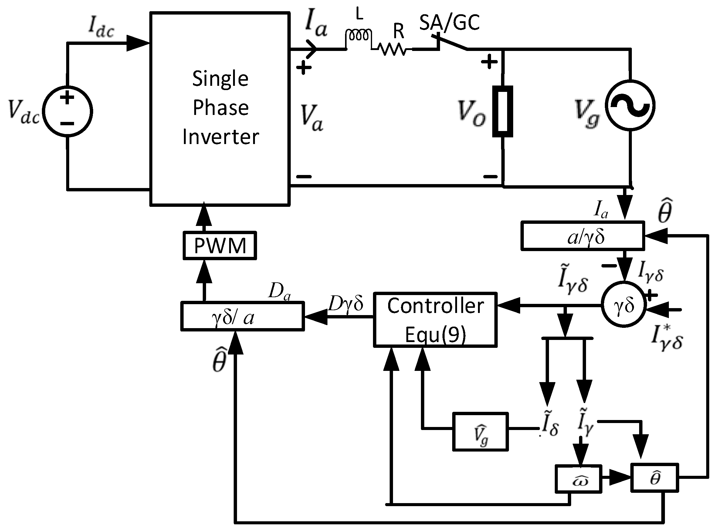
2. System Modeling
3. Control System Design and Development
Error Signal Development: To Aid in the Development of the Control, the Current Tracking Errors Are Defined in Equation (5)
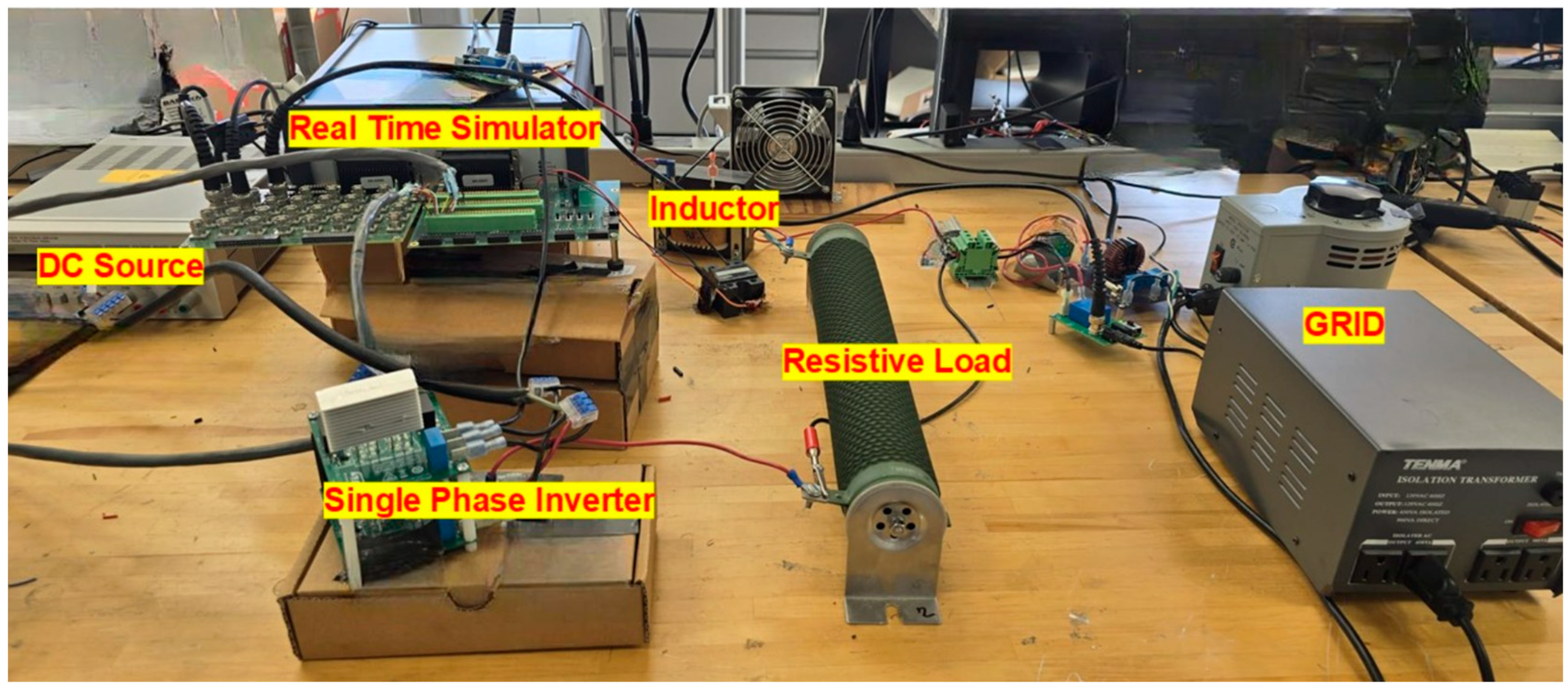
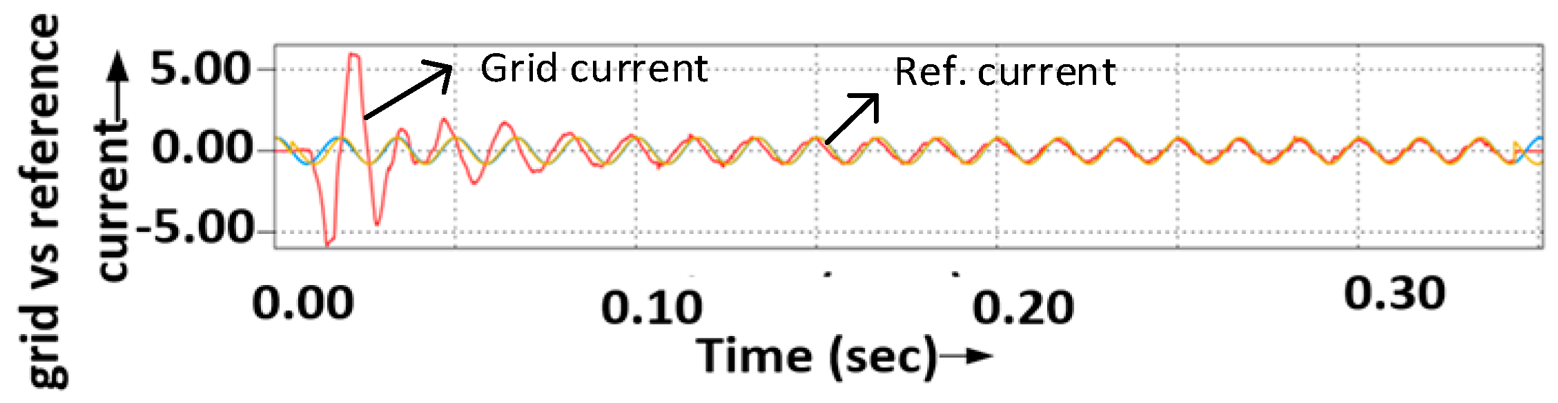
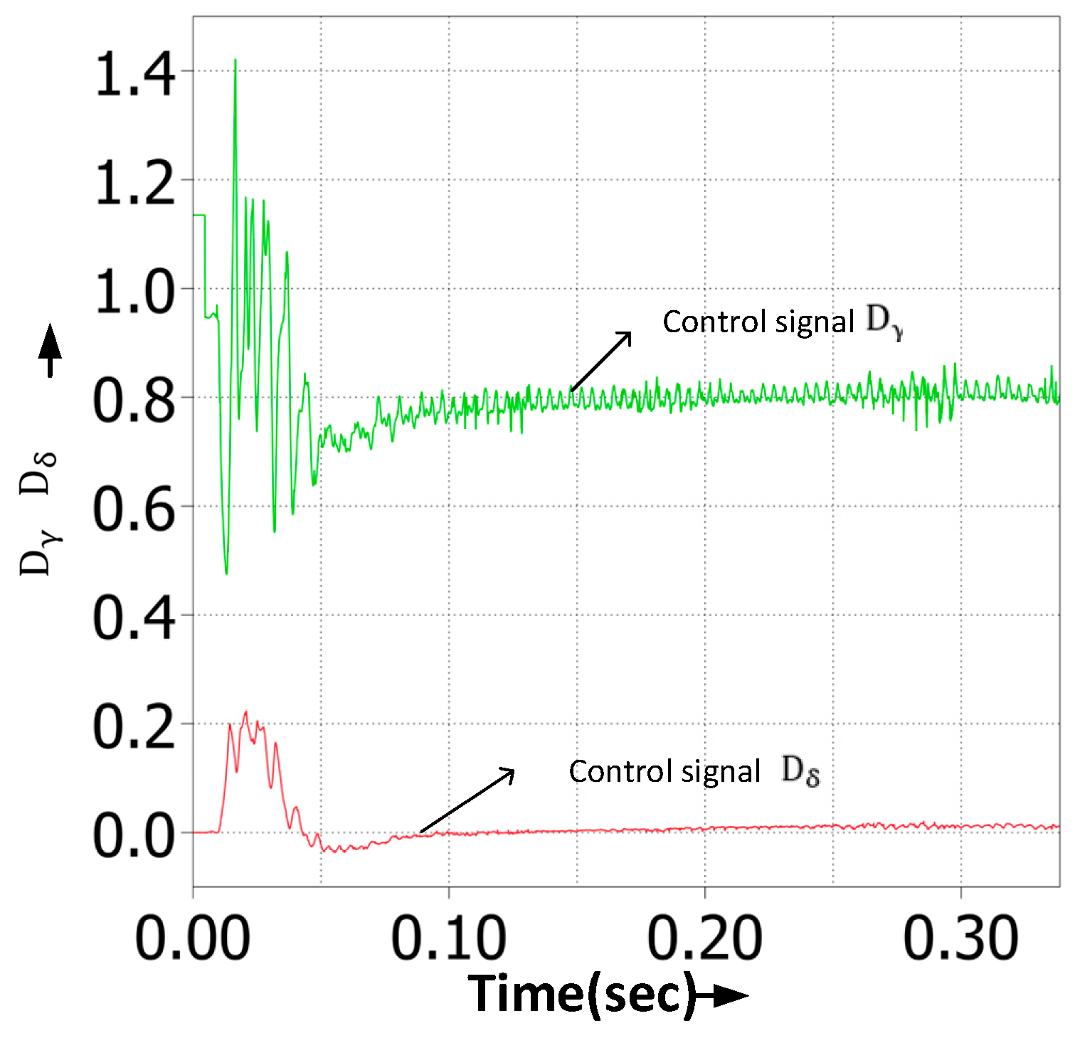
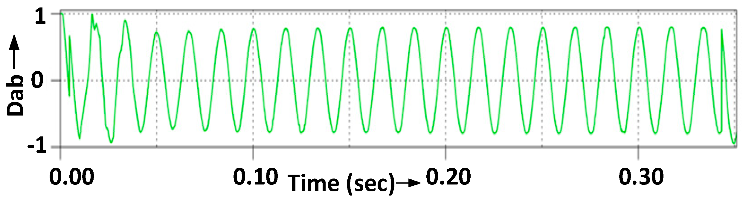
4. Hardware Results
5. Conclusions
Author Contributions
Funding
Data Availability Statement
Conflicts of Interest
References
- Khan, M.; Wu, W.; Li, L. Grid-forming control for inverter-based resources in power systems: A review on its operation, system stability, and prospective. IET Renew. Power Gener. 2024, 18, 887–907. [Google Scholar] [CrossRef]
- Pandey, S.; Damron, N.; McIntyre, M. Rapid Control Prototyping Platform for Grid Connected Electrical Energy Conversion Systems. In Proceedings of the SoutheastCon 2024, Atlanta, GA, USA, 15–24 March 2024; pp. 1599–1604. [Google Scholar]
- Kwasinski, A.; Weaver, W.; Balog, R.S. Microgrids and Other Local Area Power and Energy Systems; Cambridge University Press: Cambridge, UK, 2016. [Google Scholar]
- Arafat, M.N.; Elrayyah, A.; Sozer, Y. An Effective Smooth Transition Control Strategy Using Droop-Based Synchronization for Parallel Inverters. IEEE Trans. Ind. Appl. 2015, 51, 2443–2454. [Google Scholar] [CrossRef]
- Guerrero, J.M.; Chandorkar, M.; Lee, T.L.; Loh, P.C. Advanced Control Architectures for Intelligent Microgrids—Part I: Decentralized and Hierarchical Control. IEEE Trans. Ind. Electron. 2013, 60, 1254–1262. [Google Scholar] [CrossRef]
- Paquette, A.D.; Divan, D.M. Virtual Impedance Current Limiting for Inverters in Microgrids With Synchronous Generators. IEEE Trans. Ind. Appl. 2015, 51, 1630–1638. [Google Scholar] [CrossRef]
- Kroposki, B.; Johnson, B.; Zhang, Y.; Gevorgian, V.; Denholm, P.; Hodge, B.M.; Hannegan, B. Achieving a 100% Renewable Grid: Operating Electric Power Systems with Extremely High Levels of Variable Renewable Energy. IEEE Power Energy Mag. 2017, 15, 61–73. [Google Scholar] [CrossRef]
- Pattabiraman, D.; Lasseter, R.H.; Jahns, T.M. Comparison of Grid Following and Grid Forming Control for a High Inverter Penetration Power System. In Proceedings of the 2018 IEEE Power & Energy Society General Meeting (PESGM), Portland, OR, USA, 5–10 August 2018. [Google Scholar]
- Debdouche, N.; Benbouhenni, H.; Deffaf, B.; Anwar, G.; Zarour, L. Predictive direct power control with phase-locked loop technique of three-level neutral point clamped inverter-based active power filter for power quality improvement. Int. J. Circuit Theory Appl. 2024, 52, 3306–3340. [Google Scholar] [CrossRef]
- Rosso, R.; Engelken, S.; Liserre, M. Robust Stability Analysis of Synchronverters Operating in Parallel. IEEE Trans. Power Electron. 2019, 34, 11309–11319. [Google Scholar] [CrossRef]
- Rosso, R.; Engelken, S.; Liserre, M. Robust Stability Investigation of the Interactions Among Grid-Forming and Grid-Following converters. IEEE J. Emerg. Sel. Top. Power Electron. 2019, 8, 991–1003. [Google Scholar] [CrossRef]
- Dong, D.; Wen, B.; Boroyevich, D.; Mattavelli, P.; Xue, Y. Analysis of Phase-Locked Loop Low-Frequency Stability in Three-Phase Grid-Connected Power Converters Considering Impedance Interactions. IEEE Trans. Ind. Electron. 2015, 62, 310–321. [Google Scholar] [CrossRef]
- Sun, Y.; De Jong, E.C.W.; Wang, X.; Yang, D.; Blaabjerg, F.; Cuk, V.; Cobben, J.F.G. The Impact of PLL Dynamics on the Low Inertia Power Grid: A Case Study of Bonaire Island Power System. Energies 2019, 12, 1259. [Google Scholar] [CrossRef]
- Rosso, R.; Andresen, M.; Engelken, S.; Liserre, M. Analysis of the Interaction Among Power Converters Through Their Synchronization Mechanism. IEEE Trans. Power Electron. 2019, 34, 12321–12332. [Google Scholar] [CrossRef]
- Golpîra, H.; Seifi, H.; Messina, A.R.; Haghifam, M.R. Maximum Penetration Level of Micro-Grids in Large-Scale Power Systems: Frequency Stability Viewpoint. IEEE Trans. Power Syst. 2016, 31, 5163–5171. [Google Scholar] [CrossRef]
- Eftekharnejad, S.; Vittal, V.; Heydt, G.T.; Keel, B.; Loehr, J. Small Signal Stability Assessment of Power Systems With Increased Penetration of Photovoltaic Generation: A Case Study. IEEE Trans. Sustain. Energy 2013, 4, 960–967. [Google Scholar] [CrossRef]
- Lin, X.; Yu, R.; Yu, J.; Wen, H. Constant-Coupling-Effect-Based PLL for Synchronization Stability Enhancement of Grid-Connected Converter Under Weak Grids. IEEE Trans. Ind. Electron. 2023, 70, 11310–11323. [Google Scholar] [CrossRef]
- Huang, M.; Chen, F.; Wu, W.; Yao, Z. An adaptive phase-locked loop-less control strategy for LCL-filtered grid-connected inverter under complex grid conditions. Int. J. Circ. Theor. Appl. 2023, 51, 2105–2121. [Google Scholar] [CrossRef]
- Kumar Jalan, S.; Chitti Babu, B. Analysis of optimized phase locked loop for grid synchronization of solar PV system under grid disturbances. Int. J. Circ. Theor. Appl. 2023, 51, 5840–5858. [Google Scholar] [CrossRef]
- Ma, J.; Song, W.; Jiao, S.; Zhao, J.; Feng, X. Power Calculation for Direct Power Control of Single-Phase Three-Level Rectifiers Without Phase-Locked Loop. IEEE Trans. Ind. Electron. 2016, 63, 2871–2882. [Google Scholar] [CrossRef]
- Wang, X.; Harnefors, L.; Blaabjerg, F. Unified Impedance Model of Grid-Connected Voltage-Source Converters. IEEE Trans. Power Electron. 2018, 33, 1775–1787. [Google Scholar] [CrossRef]
- Krause, P.; Wasynczuk, O.; Sudhoff, S.D.; Pekarek, S. Reference-Frame Theory. In Analysis of Electric Machinery and Drive Systems; Wiley-IEEE Press: Hoboken, NJ, USA, 2013; pp. 86–120. [Google Scholar]
- Golestan, S.; Guerrero, J.M.; Gharehpetian, G.B. Five Approaches to Deal with Problem of DC Offset in Phase-Locked Loop Algorithms: Design Considerations and Performance Evaluations. IEEE Trans. Power Electron. 2016, 31, 648–661. [Google Scholar] [CrossRef]
- Zhong, Q.; Nguyen, P.L.; Ma, Z.; Sheng, W. Self-Synchronized Synchronverters: Inverters Without a Dedicated Synchronization Unit. IEEE Trans. Power Electron. 2014, 29, 617–630. [Google Scholar] [CrossRef]
- Cespedes, M.; Sun, J. Impedance Modeling and Analysis of Grid-Connected Voltage-Source Converters. IEEE Trans. Power Electron. 2014, 29, 1254–1261. [Google Scholar] [CrossRef]
- Mortazavian, S.; Shabestary, M.M.; Mohamed, Y.A.I. Analysis and Dynamic Performance Improvement of Grid-Connected Voltage–Source Converters Under Unbalanced Network Conditions. IEEE Trans. Power Electron. 2017, 32, 8134–8149. [Google Scholar] [CrossRef]
- Guo, X.; Wu, W.; Chen, Z. Multiple-Complex Coefficient-Filter-Based Phase-Locked Loop and Synchronization Technique for Three-Phase Grid-Interfaced Converters in Distributed Utility Networks. IEEE Trans. Ind. Electron. 2011, 58, 1194–1204. [Google Scholar] [CrossRef]
- Hui, N.; Wang, D.; Li, Y. A Novel Hybrid Filter-Based PLL to Eliminate Effect of Input Harmonics and DC Offset. IEEE Access 2018, 6, 19762–19773. [Google Scholar] [CrossRef]
- Huang, Q.; Rajashekara, K. An Improved Delayed Signal Cancellation PLL for Fast Grid Synchronization Under Distorted and Unbalanced Grid Condition. IEEE Trans. Ind. Appl. 2017, 53, 4985–4997. [Google Scholar] [CrossRef]
- Golestan, S.; Ramezani, M.; Guerrero, J.M.; Freijedo, F.D.; Monfared, M. Moving Average Filter Based Phase-Locked Loops: Performance Analysis and Design Guidelines. IEEE Trans. Power Electron. 2014, 29, 2750–2763. [Google Scholar] [CrossRef]
- Golestan, S.; Monfared, M.; Freijedo, F.D. Design-Oriented Study of Advanced Synchronous Reference Frame Phase-Locked Loops. IEEE Trans. Power Electron. 2013, 28, 765–778. [Google Scholar] [CrossRef]
- Karimi-Ghartemani, M. Universal Integrated Synchronization and Control for Single-Phase DC/AC Converters. IEEE Trans. Power Electron. 2015, 30, 1544–1557. [Google Scholar] [CrossRef]
- Ashabani, M.; Mohamed, Y.A.I. Integrating VSCs to Weak Grids by Nonlinear Power Damping Controller With Self-Synchronization Capability. IEEE Trans. Power Syst. 2014, 29, 805–814. [Google Scholar] [CrossRef]
- Guo, X.; Liu, W.; Zhang, X.; Sun, X.; Lu, Z.; Guerrero, J.M. Flexible Control Strategy for Grid-Connected Inverter Under Unbalanced Grid Faults Without PLL. IEEE Trans. Power Electron. 2015, 30, 1773–1778. [Google Scholar] [CrossRef]
- Konstantopoulos, G.C.; Zhong, Q.; Ming, W. PLL-Less Nonlinear Current-Limiting Controller for Single-Phase Grid-Tied Inverters: Design, Stability Analysis, and Operation Under Grid Faults. IEEE Trans. Ind. Electron. 2016, 63, 5582–5591. [Google Scholar] [CrossRef]
- Alqatamin, M.; McIntyre, M.L. Nonlinear Self-Synchronizing Current Control for Grid-Connected Photovoltaic Inverters. Energies 2022, 15, 4855. [Google Scholar] [CrossRef]
- Zhang, R.; Cardinal, M.; Szczesny, P.; Dame, M. A grid simulator with control of single-phase power converters in D-Q rotating frame. In Proceedings of the 2002 IEEE 33rd Annual IEEE Power Electronics Specialists Conference, Proceedings (Cat. No.02CH37289). Cairns, QLD, Australia, 23–27 June 2002; Volume 3, pp. 1431–1436. [Google Scholar]
- Khalil, H.K. Nonlinear Control; Pearson: Boston, MA, USA, 2015; 387p. [Google Scholar]


| NO. | COMPONENTS | ||
|---|---|---|---|
| 1 | Prog. DC Power Supply 300 V/5.2 A 1.56 kW | DC Supply (XLN30052) | 186 [V] |
| 2 | 1 ɸ Inverter | IGBT (STGWA20H65DFB2) | 650 [V], 20 [A] |
| 3 | Filter | L | 12 × [H] |
| 4 | R Load | R | 48 [Ω] |
| 5 | AC Source (GRID) | 140 [Vrms], 60 [Hz] | |
| 6 | Switching Frequency | 25 Khz | |
| 7 | Current control Gains | 45 | |
| 6 | |||
| 12.5 | |||
| 30 | |||
Disclaimer/Publisher’s Note: The statements, opinions and data contained in all publications are solely those of the individual author(s) and contributor(s) and not of MDPI and/or the editor(s). MDPI and/or the editor(s) disclaim responsibility for any injury to people or property resulting from any ideas, methods, instructions or products referred to in the content. |
© 2025 by the authors. Licensee MDPI, Basel, Switzerland. This article is an open access article distributed under the terms and conditions of the Creative Commons Attribution (CC BY) license (https://creativecommons.org/licenses/by/4.0/).
Share and Cite
Pandey, S.; Mclntyre, M. Nonlinear Self-Synchronizing Current Control for Single-Phase AC Inverters. Energies 2025, 18, 941. https://doi.org/10.3390/en18040941
Pandey S, Mclntyre M. Nonlinear Self-Synchronizing Current Control for Single-Phase AC Inverters. Energies. 2025; 18(4):941. https://doi.org/10.3390/en18040941
Chicago/Turabian StylePandey, Shruti, and Michael Mclntyre. 2025. "Nonlinear Self-Synchronizing Current Control for Single-Phase AC Inverters" Energies 18, no. 4: 941. https://doi.org/10.3390/en18040941
APA StylePandey, S., & Mclntyre, M. (2025). Nonlinear Self-Synchronizing Current Control for Single-Phase AC Inverters. Energies, 18(4), 941. https://doi.org/10.3390/en18040941