Article

Standardization and Modularization Strategy for the Structures of Floating Offshore Solar Power Systems

1
SPEC Engineering Y&P Co., Ltd., 201 Songpa-daero, Songpa-gu, Seoul 05854, Republic of Korea
2
TaiichiO & Wolf Projects, Calle Puerto Rico, 3 Pta 5, 46006 Valencia, Spain
3
Bluenewables Co., Ltd., Paseo de la Castellana, 121—Escalera Izquierda, 9ºB, 28046 Madrid, Spain
*
Author to whom correspondence should be addressed.
Energies 2025, 18(22), 6019; https://doi.org/10.3390/en18226019
Submission received: 10 October 2025 / Revised: 13 November 2025 / Accepted: 13 November 2025 / Published: 17 November 2025

Abstract

With the growing global need for climate change mitigation and the transition to renewable energy, the development and adoption of photovoltaic (PV) power generation technologies have accelerated significantly. However, land-based PV systems face increasing limitations due to land scarcity, high costs, and environmental constraints. Consequently, floating offshore PV systems that utilize marine environments have emerged as promising alternatives. This study introduces a novel structural redesign specifically developed to enable full containerization of floating PV platforms, adapting the PV–bos model by Spain’s BlueNewables for standardized offshore deployment. The research focuses on the standardization and modularization of floating structures to allow repetitive factory production and efficient container-based logistics. The methodology includes modular segmentation, and transportation simulation, which together establish standardized unit configurations that minimize uncertainty during manufacturing, assembly, and installation. By applying containerization principles to structural design, the study proposes standardized component dimensions and optimized container loading strategies to enhance productivity, constructability, and scalability. The novelty of this research lies in establishing a quantitative framework that integrates modular segmentation and standardized container logistics into floating PV structural design—a topic that has not been previously addressed in offshore solar studies. The results demonstrate substantial improvements in logistics efficiency and cost reduction, achieving over 80% savings in transportation CAPEX for a 0.5 MW floating PV system using 40 HC (High Cube) and 45 HC containers. Future research will complement these strategies through finite element and hydrodynamic simulations to validate the structural and environmental performance of modular joints under real marine conditions, further strengthening the technological robustness and sustainability of standardized offshore PV deployment.

1. Introduction

Recently, the necessity of responding to climate change and transitioning to eco–friendly energy has become prominent, leading to active development and dissemination of renewable energy technologies. The growth in renewable energy development strengthens the economy, reduces energy import costs, promotes self-sufficiency, and significantly contributes to improving the environment by reducing harmful substances and waste emissions [1]. Additionally, solar energy is recognized as the cleanest and most abundant renewable energy source, considered a key to a sustainable energy future. By harnessing the abundant daily energy output of the sun, it has become one of the most widely adopted energy production technologies globally [2,3].
However, conventional solar power systems typically require substantial land areas for installation, such as on mountains or ground-level areas, which significantly increases installation costs. According to relevant statistics, installing a 1 MWp PV system requires approximately 1.6 hectares of land [4,5]. Additionally, ground–mounted solar installations face issues like temperature increases, partial shading [6], and dust accumulation [7] on modules, resulting in reduced power generation efficiency. Floating marine photovoltaic (PV) systems efficiently utilize water bodies, reducing space constraints compared to terrestrial installations, and benefit from water cooling effects that enhance the efficiency of solar modules [8]. However, offshore environments present unique challenges such as waves, salinity, and strong winds, which complicate the structural design and long-term maintenance of floating PV systems. These environmental factors not only require sufficient structural stability and durability but also increase the need for systematic, standardized, and modular design approaches that can ensure reliability and simplify construction under diverse marine conditions. Therefore, recent studies have shifted their focus from conventional buoyancy optimization toward integrated design frameworks that emphasize structural standardization, modularity, and ease of assembly for offshore applications. For instance, R. Claus et al. [8] investigated various structural designs tailored to marine environments, examining structural classification and platform design adjustments based on pontoon and column arrangements. Similarly, S. J. Yoon [9] performed finite element analysis (FEA) incorporating wind tunnel and durability tests to analyze floating PV system behaviors, and also utilized FRP components to ensure structural safety and durability [10]. Despite these efforts, research on installation technology remains limited, mostly confined to selecting installation sequences for applying new designs [11].
Therefore, this paper studies the standardization and modularization of floating structures to reduce transportation and installation costs as part of efforts to advance the distribution and construction technology of floating marine PV systems. The research focuses on designing a system where all structural elements are manufactured in a factory for standard marine transportation via containers, requiring only mechanical assembly by personnel on-site. The study proposes standardization and modularization strategies from design and technical perspectives, assembly and installation aspects, and economic and logistical viewpoints, which will serve as a foundation for future detailed structural and mechanical design validation. Unlike previous studies limited to conceptual designs, this paper provides a preliminary quantitative assessment of logistics efficiency and standardization strategies for modular floating PV structures, offering a practical direction for future industrial applications. The remainder of this paper is structured as follows. Section 2 introduces the conceptual floating marine photovoltaic (PV) system model and explains the modularized structural design approach. Section 3 presents the standardization and modularization strategies, including component segmentation and transportation simulations. Section 4 provides the main conclusions and implications for offshore PV system development.

2. Floating Marine Photovoltaic System Model

2.1. Floating Structure Model Concept

The floating structure model for marine photovoltaic systems considered in this study is based on the initial concept developed in 2021 by the Spanish company BlueNewables (Valencia, Spain), which combines innovations from shipbuilding, oil and gas (O&G), and marine renewable energy sectors The original model, named PV–bos, adopts a catamaran configuration composed of tubular steel hulls, providing high buoyancy and structural stability in offshore environments conditions.
While the BlueNewables PV–bos concept establishes a reliable foundation for offshore PV design, the present study advances this concept through a novel simplification and reconfiguration of the structural system to enable containerized manufacturing, modular assembly, and standardized logistics. Unlike the original model focused on prototype–scale offshore demonstration, this work introduces engineering standardization and modularization strategies that make repetitive mass production and automated installation feasible using globally transportable components.
The proposed model conceptually adopts modular segmentation of pontoons, braces, and nodes to explore the feasibility of standardizing structural components within container dimension limits (≤12 m). This conceptual framework aims to provide potential pathways for achieving cost efficiency and practical scalability in offshore PV projects across diverse marine environments. The key features of the floating structure are as follows (adapted from the BlueNewables technical concept) [12]:
  • A floating platform formed by two tubular hulls in a catamaran configuration.
  • Solar panels are securely attached to the floating platform via robust support structures.
  • Sufficient air gap (distance above the maximum water level) is maintained to minimize direct wave impact on the solar panels.
The floating platform (Figure 1) is primarily composed of the floating body (hull) and the supporting structure for solar panels (PV module frame).
The hull consists of two main cylinders connected by a series of smaller-diameter tubes (bracings) arranged horizontally and diagonally. The main cylinders and bracings provide buoyancy to the system and are made of steel tubes, offering advantages of simple fabrication and cost-effective installation.
The PV module serves as the structural frame supporting the solar panels, while the solar panels themselves are electronic devices that absorb solar energy and convert it into electricity. The module structure holds the panels at a fixed orientation and position to maximize power generation efficiency and also includes auxiliary structural components and equipment necessary for operation and maintenance.
The deck (module-supporting structure) is rigidly connected to the hull through a series of vertical and diagonal columns, the lengths of which vary depending on site-specific significant wave heights. In addition, this study extends the structural design methodology by linking modular standardization to sustainability and circular economy principles, where component reuse and repairability are prioritized in long-term offshore operation. This provides a significant step forward in bridging industrial practicality with renewable infrastructure scalability.
Recent studies—such as Numerical Study of Soft-Connected Modular Offshore Floating Photovoltaic Array by Baniya et al. [13], A New Web-Type Concept of Floating Photovoltaic Farms in Open Sea Environment by Yuan et al. [14], and Floating Photovoltaics: Assessing the Potential, Advantages, and Challenges of Harnessing Solar Energy on Water Bodies by Amer et al. [15]—have explored various modular and flexible structural approaches for floating photovoltaic systems. These works demonstrate a growing academic interest in improving structural efficiency, scalability, and adaptability for offshore solar platforms, and collectively suggest that developing standardized modular frameworks could be an important next step for enhancing the resilience and practicality of ocean-based PV systems.
In alignment with these research directions, the present study proposes a conceptual modular framework for floating PV platforms, emphasizing modularity, interconnectivity, and structural adaptability—aspects that remain underexplored compared to offshore wind-based modular systems. This conceptual framework positions floating PV development within the broader evolution of offshore renewable energy technology. Recent advancements in hybrid offshore energy platforms, mooring optimization, dynamic stability control, and hydrodynamic modeling for wave–structure interactions indicate an increasing convergence of design methodologies across renewable domains. By extending the principles of standardization and modularization—commonly applied in offshore wind and oil & gas infrastructures—to the domain of floating photovoltaics, this study aims to provide a conceptual foundation for the development of integrated, scalable, and cross-compatible offshore renewable infrastructures, bridging floating solar systems with hybrid ocean energy platforms and established marine engineering standards.

2.2. Floating Structure Model for Modularization and Standardization

The floating marine photovoltaic (PV) structure examined in this study is based on a 0.5 MW system (Figure 2), which corresponds to the prototype scale adopted in the BlueNewables PV–bos model (2021).
The reference model has an overall width of 42.8 m and a length of 67.3 m. Its structure consists of circular steel tubular main hulls interconnected with columns, diagonal bracings, and horizontal bracings. The specifications and functional roles of the structural components are summarized in Table 1.
In the BlueNewables design, the floating platform was originally developed as a welded steel structure for a 0.5 MW photovoltaic capacity. To ensure direct comparability with that reference model, the present study retains the same power scale but conceptually reinterprets the configuration as a modularized and standardized framework. This scale was selected because BlueNewables is currently fabricating and testing the PV–bos prototype at the 0.5 MW capacity, which provides a realistic benchmark for evaluating the potential logistical and economic benefits of modularization.
The purpose of this conceptual modification is to illustrate the logistical and construction advantages that could be achieved if the welded components of the original PV–bos model were segmented into container-transportable modules and assembled on-site using bolted connections. This approach serves as a conceptual example of how modularization could improve transportation efficiency, assembly flexibility, and scalability, thereby supporting the development of a practical industrial framework for offshore deployment.
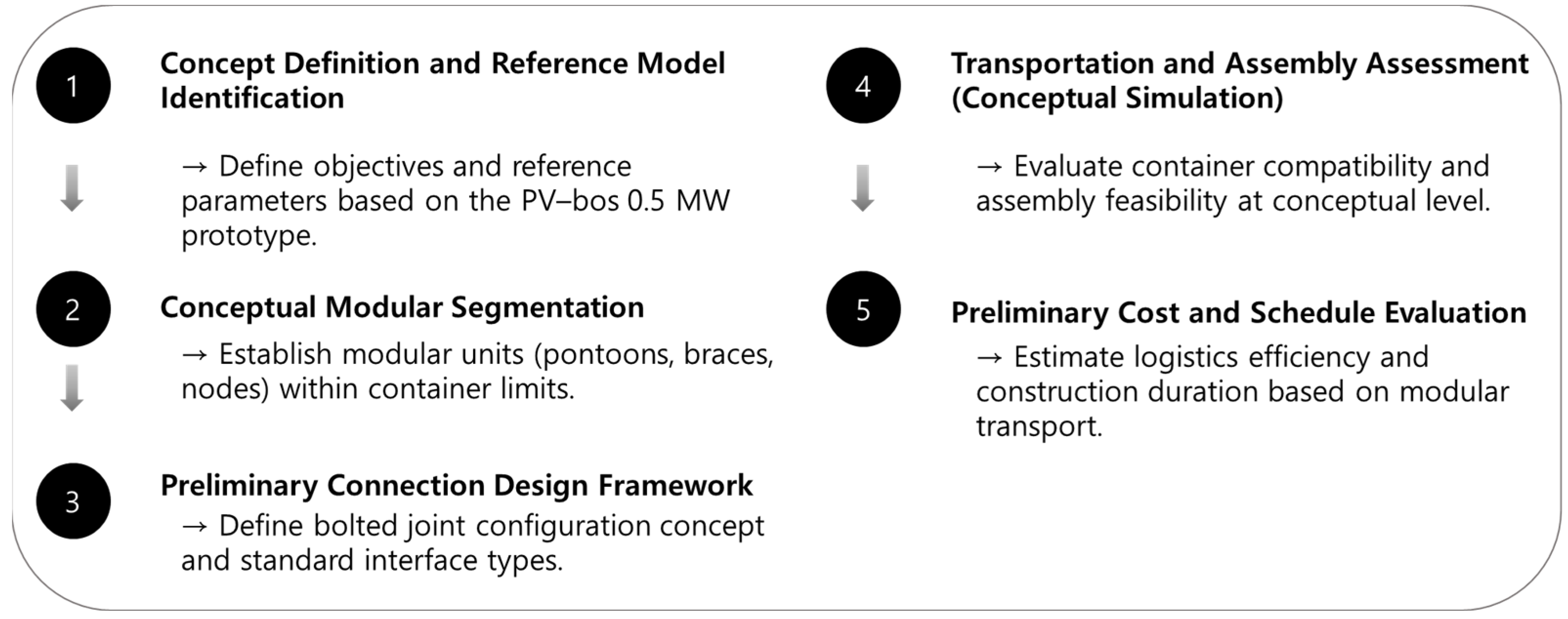
To provide a clear overview of the proposed methodology, Figure 3 presents a general conceptual flowchart outlining the sequential stages of the standardization and modularization process—including conceptual model definition, modular segmentation, connection design, transportation assessment, and cost/schedule evaluation. Rather than describing a finalized engineering design, this framework provides the methodological foundation for future detailed analyses involving structural, hydrodynamic, and fatigue validation.

3. Standardization and Modularization

3.1. Standardization and Modularization Strategy

The strategy for standardization and modularization for PV–bos, firstly introduced by the company TaiichiO & Wolf Projects (Madrid, Spain), was established to simplify and standardize the floating platform assembly process, enabling construction with minimal technical expertise. In this study, standardization implies minimizing diversity by using repetitive components to facilitate automated mass production. Modularization involves segmenting components into standardized units to enhance production, transportation, and assembly convenience.
The primary focus of standardization and modularization was the floating device. The structural dimensions and component assembly methods were analyzed to establish technical strategies enabling repetitive factory production and convenient transportation and assembly. These strategies aimed to achieve efficiency in assembly and installation, as well as economic and logistical benefits (Table 2).
  • Technical Design Strategy: Establish standard dimensions for structural components considering production and transportation conditions (within 2.6 m × 12 m). Components are selected and divided to enable repetitive production within these dimensions. Module dimensions and shapes are selected, and connection structures are designed for easy transportation and onsite assembly.
  • Assembly and Installation Efficiency: Through design approaches that prioritize ease of onsite assembly, the floating device can be constructed quickly and accurately. The modular components are interconnected using bolt connections, employing techniques such as Poka–yoke methods and double bolting from inside and outside to avoid the need for specialized equipment or highly skilled personnel. This minimizes human errors and enhances operational efficiency and reliability. Moreover, modular components are independently designed, enabling quick replacement or repair of specific modules in case of failures or aging. Standardized components allow consistent global availability, reducing inventory risks and maintenance costs, and improving overall system stability and sustainability.
  • Economic and Logistical Benefits: Simplified modular forms suitable for mass production enhance productivity, shorten construction periods, and improve economic viability. The modular structure facilitates standard maritime container transportation, significantly reducing transportation costs. Additionally, bolted connections make the system adaptable to specific local conditions, such as in Southeast Asia, particularly Indonesia, where specialized environmental and policy considerations exist. This eliminates the need for specialized equipment or personnel for module connections, thereby enabling tailored logistics strategies, ultimately reducing overall logistics costs.

3.2. Component Segmentation for Standardization and Modularization

3.2.1. Component Segmentation of the Basic Model

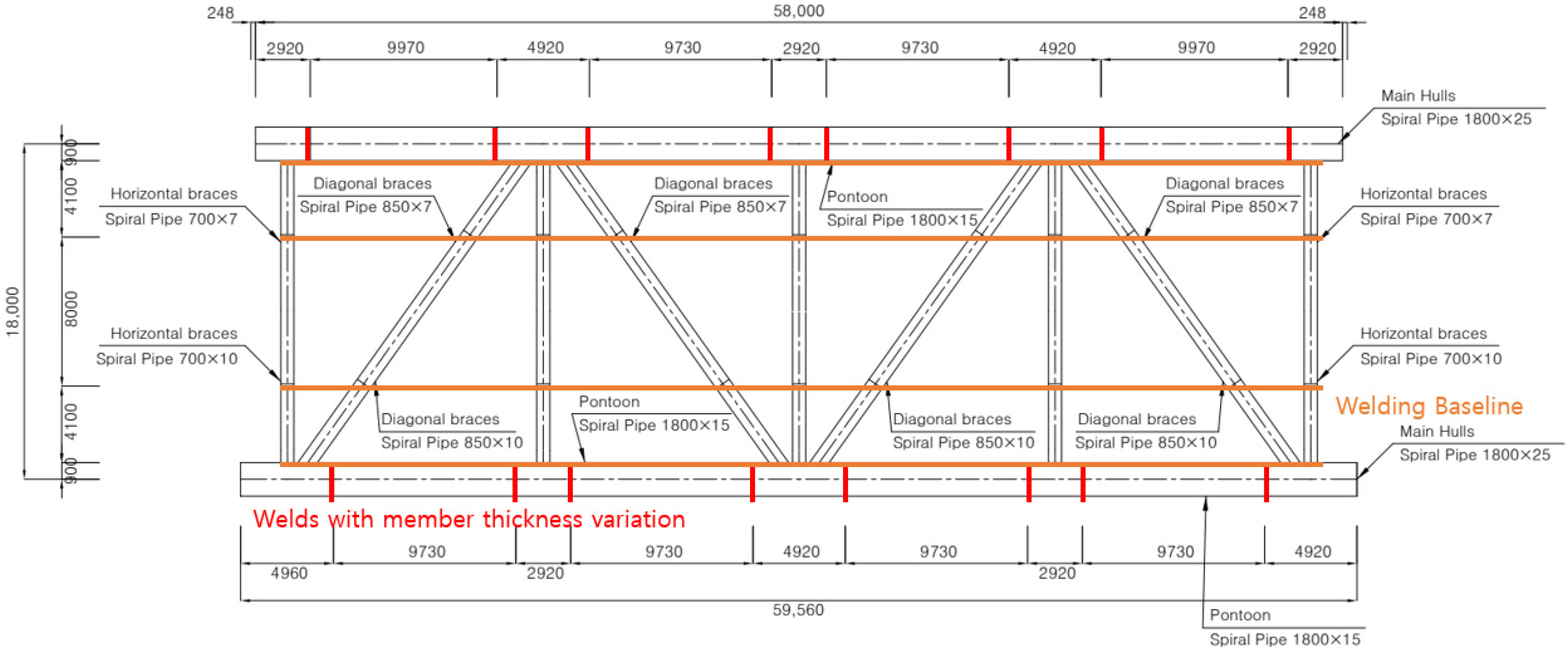
The 0.5 MW PV-bos floating-platform model was used as the baseline to develop a segmentation strategy for structural standardization and modularization. In the original welded design, the Main Hull, Diagonal Braces, and Horizontal Braces were connected by on-site welding. Welds were categorized into three groups: (1) joints between the Main Hull and Braces, (2) joints between Braces, and (3) areas on the Main Hull where plate thickness changes due to brace attachment (Figure 4).
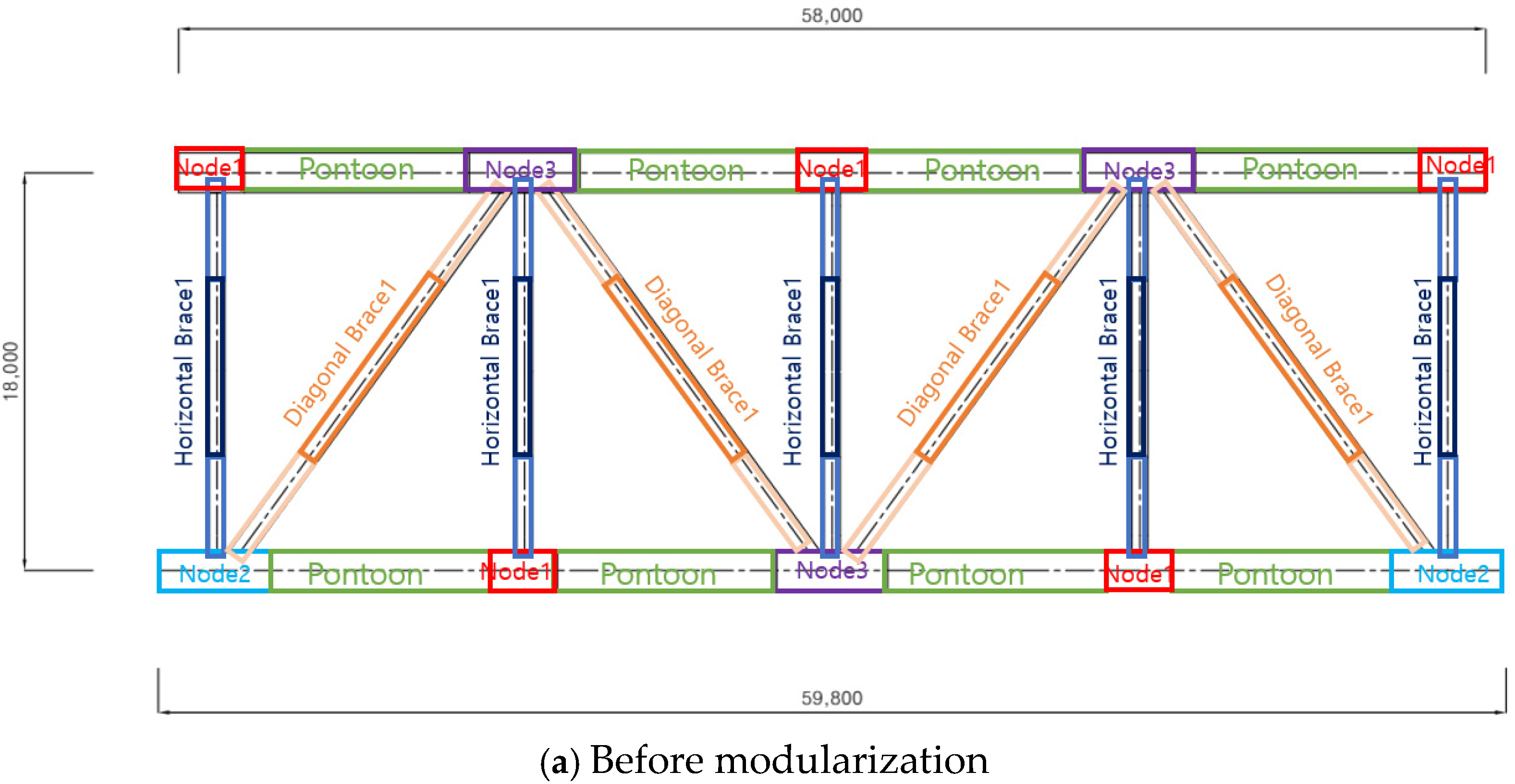
In the standardized configuration, these regions were redefined as Pontoons and Nodes, which serve as modular units compatible with containerized transport. Each structural member was segmented so that its total length did not exceed 12 m, ensuring compatibility with 40 HC containers. This segmentation forms the foundation of the modular structure proposed in this study.
In addition, the segmentation criteria for pontoons, nodes, and braces were established using a unified decision sequence that considers structural continuity, container dimensional limits, and fabrication repeatability. These criteria ensure that each segmented module maintains sufficient stiffness while enabling consistent manufacturability and predictable on-site assembly performance. Furthermore, the transportation loading assessment followed a standardized loading rule based on dimensional fit, axial symmetry, and lifting-clearance requirements to prevent excessive local deformation during shipping.

3.2.2. Review of Structural Member Connections for Modularization

To enable modularization, welded joints were replaced with bolted flange connections at the ends of each segmented member. This transition aligns with international offshore design codes—DNV-OS-C101 (2019) [16], ISO 19902 (2020) [17], and AISC 360 (2016) [18]—which specify that properly pre-tensioned high-strength friction-grip (HSFG) bolts, with suitable surface treatment and corrosion protection, can achieve equivalent strength and fatigue performance to welded joints under offshore loading. Thus, the proposed bolted connection is considered structurally reliable for modular floating structures.
The bolted system allows rapid on-site assembly without specialized tools or skilled labor. A Poka-yoke-based connection concept ensures correct alignment by preventing improper assembly, minimizing human error, and improving safety and repeatability. This approach simplifies construction and facilitates easy disassembly, repair, and replacement of modular components throughout the system’s lifecycle. Verification of the bolted connection design is in progress. Based on the reference PV-bos model, the maximum bending moment expected at the main hull section was approximately 1.5 MN·m in the longitudinal (Mx) direction. To withstand this design moment while ensuring equivalent strength and fatigue resistance to welded joints, a bolted flange configuration with forty (40) M36 high-strength bolts (Grade 10.9) was adopted in accordance with DNV-OS-C101, EN 1993-1-8 [19], and DNVGL-RP-C203 [20] standards. The selected bolt arrangement provides sufficient tensile and shear capacity under combined bending and axial loads, with bolts pre-tensioned to 70% of the yield stress to secure slip resistance and long-term fatigue durability under cyclic offshore loading. This configuration, originally derived from the “Flanges and Joints Typologies” report [21] serves as the baseline for finite-element verification of modular pontoon connections.
Preliminary finite-element analysis (FEA) and fatigue load simulations are being conducted to evaluate mechanical behavior under dynamic offshore conditions (waves, wind, and currents). These analyses also assess how the 12 m segmentation constraint influences global stiffness, stress distribution, and hydrodynamic response, confirming that containerization does not compromise structural integrity.
Results of these simulations will be reported in future publications.
To further enhance validation, future work will incorporate site-specific marine parameters—including wave spectra, significant-wave-height distributions, wind-load profiles, and salinity-driven corrosion models—into coupled FEA–hydrodynamic simulations. This will allow realistic assessment of assembly feasibility, global stability, and lifecycle durability under representative offshore environments.
The framework will quantitatively evaluate how wave-induced stress cycles and chloride-induced corrosion affect modular connection reliability and maintenance needs.
Additionally, the long-term reliability of offshore PV systems is influenced by oxidation kinetics and interface stability of metallic and semiconductor surfaces in saline, humid conditions. These phenomena affect both the mechanical integrity of joints and the electrical stability of PV modules.
Future research will thus investigate surface oxidation mechanisms, corrosion-resistant coatings, and interfacial degradation pathways, as emphasized in recent studies [22,23].
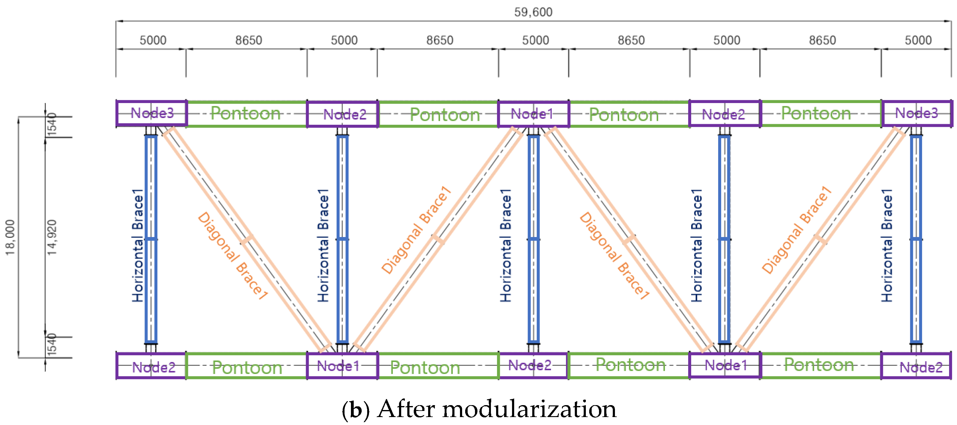
Integrating these material-level insights into modular design optimization will be essential to ensuring mechanical robustness and electrical longevity. Finally, the modular geometry was optimized to simplify manufacturing and improve reusability. The Pontoon length was reduced from 59.6 m to 8.65 m by dividing it into four segments (eight pieces in total, for both directions), allowing full container transportability. Although this segmentation slightly increased steel consumption, it significantly enhanced manufacturability and logistical efficiency.
The introduction of standardized Nodes also simplified the system from four brace types (two horizontal, two diagonal) to only two. Consequently, the standardized configuration now consists of one Pontoon type, two Node types, one Horizontal Brace, and one Diagonal Brace (Figure 5), establishing a practical and scalable foundation for modular offshore PV construction. The member segmentation and standardization results are summarized in Table 3.

3.3. Review of Transportation Efficiency for Standardized and Modular Members

3.3.1. Review of Transportation of Segmented Components Using Containers

To ensure compatibility between segmented structural components and transportation methods, the container loading capabilities of the members were reviewed. Container specifications were examined based on the dimensions of the Main Pontoon diameter and the flange connections designed for bolting the Main Pontoon and Braces. The review was conducted using 40 HC (40-foot High Cube) and 45 HC (45-foot High Cube) containers as standards [24]. The previously segmented members were designed to repeat dimensions within approximately 12,000 mm to 13,500 mm, suitable for loading into 40 HC and 45 HC containers. Considering the 20 DV (20-foot Dry Van) container was excluded, as it would double the number of segmentations required, resulting in inefficiencies resulting in inefficiencies, as shown in Figure 6.
The container loading review in this study was conducted under idealized packing assumptions, focusing primarily on dimensional fit within 40 HC and 45 HC containers. In practice, container utilization can be affected by operational factors such as weight distribution, lifting clearance, and securing requirements. These practical constraints will be further evaluated in future logistics simulations to reflect more realistic transport and handling conditions.
Table 4 presents the required quantities of materials for the installation of one 0.5 MW unit, classified by member type. Members were categorized as Pontoon, Node, Horizontal Brace, and Diagonal Brace. Nodes were further classified based on the number and orientation of flanges used to connect Braces, even when their sizes were identical. Each member was detailed by total length, element length, width, height, and the number of individual components. For instance, the Pontoon has a total length of 69,200 mm and is constructed from steel pipes with a diameter of 1800 mm. To enable container loading, it requires segmentation into nine pieces, each measuring 8650 mm in length, with each piece having dimensions of 1800 mm by 1800 mm, allowing one unit per container.
Table 5 shows the number of containers required for loading the structural members listed in Table 2. Container capacity calculations were based on each member’s width, height, and length, determining the total number of containers needed for a single installation. For example, Pontoon segments require one container per segment, totaling nine containers, whereas Node 1 can accommodate two segments per container, thus requiring two containers in total. Ultimately, the analysis calculated a total of 19 containers needed for mixed loading and 21 containers when mixed loading was not considered.

3.3.2. Cost Review for Container Transportation

To evaluate the economic feasibility of container transportation, the costs associated with transporting pre-assembled PV–bos units using tugboats and containerized shipping were analyzed (Table 6). For example, transportation from Busan to a port near Jakarta, Indonesia, using a 4500-horsepower tugboat traveling at 5 knots (approximately 9.3 km/h) over a distance of approximately 4600 km would take around 20 days [25], with an average daily operation cost of USD 20,000, resulting in a total cost of approximately USD 400,000 [26,27].
In contrast, container transport involves total shipping costs of about USD 3000 per 40 HC container, yielding approximately USD 57,000 for 19 containers. When including local assembly costs—comprising local labor (USD 20 per day per worker) [28] and heavy lifting equipment rental (approximately USD 3000 per day for a 200-ton crawler crane)—the total container-based logistics cost amounts to USD 66,360 [29].
Even after accounting for port fees, insurance, and handling costs (while excluding storage and consumables), container transportation still represents only about 17% of the tugboat transportation cost, clearly demonstrating its superior economic efficiency.
The cost analysis presented herein was based on conservative, yet simplified assumptions derived from published industrial benchmarks and indicative rates from Southeast Asian logistics providers. While these assumptions enable a transparent comparison between tugboat and containerized transport, they do not fully capture regional price variability, port handling surcharges, or insurance costs. Therefore, future research will refine these estimates through market-validated quotations and multi-scenario techno-economic modeling to ensure that the cost savings reported here remain representative under realistic conditions.
Furthermore, to provide a normalized basis for comparison and to facilitate the use of these data in potential project finance studies, logistics costs were expressed in terms of CAPEX per unit power capacity (USD per kWp). Assuming a 0.5 MW system, the logistics CAPEX was calculated as 132,720$/MW for container transportation and 800,000 $/MW for tugboat transportation, resulting in 667,280 $/MW savings (approximately 83% reduction). This normalization enhances interpretability without requiring any detailed financial or feasibility analysis.
In addition to cost evaluation, the construction schedule efficiency was reviewed based on containerized modular assembly. If the average port handling time per container is assumed as t_port = 0.15 day, and the average on–site assembly time per container is t = 0.25 day, with p = 2 assembly teams, the total duration per system (N = 19 containers) can be calculated as follows:
  • Days per unit = N × (t_port + t)/p = 19 × (0.15 + 0.25)/2 = 3.8–4.2 days.
  • Days per MW = 7.6–8.4 days/MW.
The time parameters (t_port and t) were reasonably assumed with reference to industrial logistics benchmarks and prior offshore PV installation studies, reflecting typical handling and assembly durations observed in modular offshore construction projects. These results indicate that the modular container transportation method not only reduces logistics CAPEX but also provides a predictable and manageable construction schedule, further supporting its suitability for standardized offshore PV deployment.

3.3.3. Sensitivity to Market Fluctuations

To test robustness against market uncertainty, a one-way sensitivity analysis was performed on three drivers: container freight rates (±20%), tugboat fuel prices (±15%), and assembly labor cost (±10%). For containerized logistics, only the ocean–freight component varies with freight rate (base: USD 57,000 for 19 × 40 HC), while local assembly labor and lifting equipment costs vary with labor cost (base: USD 360) and remain fixed for lifting (USD 9000). The resulting total container logistics cost ranges from USD 54,924 (−20% freight, −10% labor) to USD 77,796 (+20% freight, +10% labor).
For tugboat transport, total cost sensitivity depends on the fuel share (α) of the daily operating cost. The total tugboat cost scales as: C t u g = 400,000 × ( 1 ± 0.15 α )
For a representative case with α = 0.5, the range is USD 370,000–430,000.
Across all tested combinations (container high vs. tugboat low and vice versa), containerized transport remains economically favorable; even in the most conservative comparison (USD 77,796 vs. USD 370,000), the container option is ~21% of tugboat cost (≈79% savings), and in the most favorable case (USD 54,924 vs. USD 430,000) it is ~13% (≈87% savings). These results confirm that the proposed modular logistics approach is robust to realistic market fluctuations while maintaining ≥70% cost savings. Detailed numerical results for the sensitivity cases are presented in Table 7.
  • Container totals vary only with ocean–freight and labor; lifting equipment kept at USD 9000.
  • Tugboat total varies with fuel via C t u g = 400,000 × ( 1 ± 0.15 α ) ; table uses α = 0.5 as a representative case.
  • For normalized logistics CAPEX ($/MW), multiply each “Total” by 2 (0.5 MW system). Thus, container ranges 109,848–155,592 $/MW, tugboat ranges 740,000–860,000 $/MW for α = 0.5.
According to Table 8, containerized transport results in a construction schedule reduction of approximately 16 days per unit and 32 days per MW relative to tugboat transportation.

4. Results and Discussion

The proposed modular container-based floating PV structure demonstrates significant advantages in logistics efficiency, assembly time, and cost competitiveness compared with conventional tugboat transportation systems. The total logistics cost was reduced by approximately 83%, primarily due to standardized component dimensions and high container utilization. Even when accounting for ±20% fluctuations in freight and fuel prices, the cost savings remain above 70%, confirming the robustness of the containerization strategy.
Structurally, the segmentation of the main pontoons to ≤12 m enables compatibility with 40 HC containers without compromising stiffness or buoyancy. Although additional joints introduce localized stress concentrations, these effects can be mitigated through double-nut bolted connections and fatigue-resistant design following DNV RP–C203 guidelines.
The findings collectively support the feasibility of container-based modularization as a viable pathway for the industrial-scale deployment of offshore floating PV systems. However, further FEA validation and hydrodynamic coupling simulations are required to confirm long-term performance under irregular wave loading and corrosion exposure.
This study thus establishes a quantitative foundation for integrating structural modularity, logistics optimization, and standardization into a unified offshore PV design framework.

5. Conclusions

This study explored standardization and modular design strategies to accelerate the deployment of floating offshore photovoltaic (PV) systems as part of global climate-change mitigation and renewable-energy transition efforts. While conventional floating structures are typically fabricated onshore and transported by tugboats, this research proposed an alternative approach in which the structural components of the floating platform are prefabricated and transported via standard containers for offshore delivery and on-site assembly.
The major structural components of the platform—Pontoon, Horizontal Brace, and Diagonal Brace—were standardized in both specification and geometry to enhance production efficiency and transportation economy. A bolted connection system was introduced to maximize on-site assembly convenience and reduce dependency on specialized labor. In particular, the standardization of Node and Brace members significantly improved manufacturability and logistical efficiency, demonstrating the feasibility of a scalable modular design framework.
The proposed bolted connections will be designed in accordance with offshore structural standards, including DNV RP–C203 and ISO 898–1, to ensure adequate preload capacity, fatigue resistance, and corrosion protection under cyclic marine conditions. Each joint is planned to incorporate double-nut locking and gasket sealing to maintain watertightness and prevent preload loss due to vibration. High-strength carbon-steel bolts (Grade 10.9) with zinc–aluminum coating will be adopted to resist seawater-induced corrosion, and all interfaces will be configured for periodic inspection and torque re-tightening. A detailed finite-element (FEA) verification of stress concentration and fatigue performance will be conducted in future work as part of the validation phase of this research.
Containerization analysis indicated that approximately 19 to 21 containers are required to transport components for a 0.5 MW unit. Mixed loading of multiple components further improves transport efficiency. Cost and schedule comparisons between container shipping and conventional tugboat transport revealed over 83% savings in logistics CAPEX (about USD 667,000 per MW), with construction duration shortened from approximately 20 days to 3.8–4.2 days per unit (7.6–8.4 days per MW). These results confirm that container-based modular transport ensures both economic and temporal efficiency, establishing a solid foundation for large-scale offshore PV deployment.
The adoption of standardized and optimized PV-bos configurations is expected to simplify component types for mass production, reduce material consumption and production costs, and shorten construction timelines while lowering labor costs. Containerized logistics also eliminate the need for selecting local fabricators, thereby improving project execution efficiency. This approach is anticipated to enhance global scalability and competitiveness in the offshore renewable-energy market.
The application of standardization and modularization provides technical, economic, and social benefits, offering a critical strategy for improving the efficiency and sustainability of marine solar power systems. Future research will focus on refining the proposed framework through FEA-based structural verification, hydrodynamic coupling simulations, and environmental durability analyses to ensure long-term reliability under realistic offshore conditions. Additionally, life-cycle assessment (LCA) and techno-economic optimization will be conducted to evaluate the environmental and economic implications of large-scale implementation. These efforts will contribute to developing a comprehensive and globally applicable design methodology for standardized floating PV systems in diverse marine environments. Despite these advantages, this study remains conceptual in nature and does not include full-scale hydrodynamic or fatigue-based lifecycle validation. The proposed modular framework therefore requires further verification through long-term experimental data, large-scale prototype testing, and coupled FEA–hydrodynamic simulations under irregular sea states. Future work will integrate these analyses to establish a more comprehensive design methodology and performance assessment framework for standardized floating PV systems.

Author Contributions

Conceptualization, A.E.; Validation, K.L., M.K., A.E. and O.S.; Formal analysis, K.L. and M.K.; Investigation, A.E.; Resources, O.S.; Writing—original draft, K.L.; Writing—review & editing, M.K.; Visualization, O.S.; Supervision, M.K. All authors have read and agreed to the published version of the manuscript.

Funding

This research was funded by Ministry of Trade, Industry and Energy and the Korea Institute for the Advancement of Technology, grant number P0027945.

Data Availability Statement

The original contributions presented in this study are included in the article. Further inquiries can be directed to the corresponding author.

Conflicts of Interest

Authors Kyusuk Lee and Moonok Kim were employed by the company SPEC Engineering Y&P Co., Ltd. Author Oscar Sainz was employed by the company Bluenewables Co., Ltd. The remaining authors declare that the research was conducted in the absence of any commercial or financial relationships that could be construed as a potential conflict of interest.

Abbreviations

Symbol/AcronymDefinition
PVPhotovoltaic
FEAFinite Element Analysis
FRPFiber-Reinforced Polymer
CAPEXCapital Expenditure
O&GOil and Gas
HCHigh Cube
DVDry Van
MWMegawatt
kWpKilowatt-peak
t_portAverage port handling time per container (days)
tAverage on-site assembly time per container (days)
pNumber of assembly teams
NNumber of containers per unit
αFuel cost share in tugboat operation
USDUnited States Dollar

References

  1. Djalab, A.; Djalab, Z.; El Hammoumi, A.; Tina, G.M.; Motahhir, S.; Laouid, A.A. A comprehensive Review of Floating Photovoltaic Systems: Tech Advances, Marine Environmental Influences on Offshore PV Systems, and Economic Feasibility Analysis. Sol. Energy 2024, 277, 112711. [Google Scholar] [CrossRef]
  2. Ren21. Renewables 2019 Global Status Report. 2019. Available online: https://www.ren21.net/ (accessed on 12 November 2025).
  3. El Hammoumi, A.; Chalh, A.; Allouhi, A.; Motahhir, S.; El Ghzizal, A.; Derouich, A. Design and construction of a test bench to investigate the potential of floating PV systems. J. Clean. Prod. 2021, 278, 123917. [Google Scholar] [CrossRef]
  4. Kabir, E.; Kumar, P.; Kumar, S.; Adelodun, A.A.; Kim, K.-H. Solar energy: Potential and future prospects. Renew. Sustain. Energy Rev. 2018, 82, 894–900. [Google Scholar] [CrossRef]
  5. Sreenath, S.; Sudhakar, K.; Af, Y. 7E analysis of a conceptual utility–scale land–based solar photovoltaic power plant. Energy 2021, 219, 119610. [Google Scholar] [CrossRef]
  6. Teo, J.C.; Tan, R.H.G.; Mok, V.H.; Ramachandaramurthy, V.K.; Tan, C. Impact of Partial Shading on the P–V Characteristics and the Maximum Power of a Photovoltaic String. Energies 2018, 11, 1860. [Google Scholar] [CrossRef]
  7. Zitouni, H.; Azouzoute, A.; Hajjaj, C.; El Ydrissi, M.; Regragui, M.; Polo, J.; Oufadel, A.; Bouaichi, A.; Ghennioui, A. Experimental investigation and modeling of photovoltaic soiling loss as a function of environmental variables: A case study of semi–arid climate. Sol. Energy Mater. Sol. Cells 2021, 221, 110874. [Google Scholar] [CrossRef]
  8. Claus, R.; López, M. Key issues in the design of floating photovoltaic structures for the marine environment. Renew. Sustain. Energy Rev. 2022, 164, 112502. [Google Scholar] [CrossRef]
  9. Yoon, S.J.; Joo, H.J.; Kim, S.H. Structural analysis and design for the development of floating photovoltaic energy generation system. Mater. Sci. Eng. 2018, 372, 12021. [Google Scholar] [CrossRef]
  10. Choi, J.-W.; Joo, H.-J.; Nam, J.-H.; Hwang, S.-T.; Yoon, S.-J. Performance Enhancement of Floating PV Generation Structure Using FRP. Compos. Res. 2013, 26, 105–110. [Google Scholar] [CrossRef]
  11. Sahu, A.; Yadav, N.; Sudhakar, K. Floating photovoltaic power plant: A review. Renew. Sustain. Energy Rev. 2016, 66, 815–824. [Google Scholar] [CrossRef]
  12. BlueNewables. PV–bos: Offshore Photovoltaic Floating Platform; BlueNewables Technical Report; BlueNewables: Madrid, Spain, 2018. [Google Scholar]
  13. Baniya, J.; Dai, J.; Jiang, Z.; Zhang, C. Numerical study of soft-connected modular offshore floating photovoltaic array. Mar. Struct. 2025, 104, 103893. [Google Scholar] [CrossRef]
  14. Yuan, Z.-M.; Yu, S.-R.; Incecik, A. A New Web-Type Concept of Floating Photovoltaic Farms in Open Sea Environment. Engineering 2025. [Google Scholar] [CrossRef]
  15. Amer, A.; Attar, H.; As’ad, S.; Alsaqoor, S.; Colak, I.; Alahmer, A.; Alali, M.; Borowski, G.; Hmada, M.; Solyman, A. Floating Photovoltaics: Assessing the Potential, Advantages, and Challenges of Harnessing Solar Energy on Water Bodies. J. Ecol. Eng. 2023, 24, 324–339. [Google Scholar] [CrossRef]
  16. DNV-OS-C101; Design of Offshore Steel Structures, General (LRFD Method). DNV: Høvik, Norway, 2019.
  17. ISO 19902; Fixed Steel Offshore Structures. International Organization for Standardization: Geneva, Switzerland, 2020.
  18. AISC 360-16; Specification for Structural Steel Buildings. American Institute of Steel Construction: Chicago, IL, USA, 2016.
  19. EN 1993-1-8; Eurocode 3—Design of Steel Structures—Part 1-8: Design of Joints. European Committee for Standardization (CEN): Brussels, Belgium, 2005.
  20. DNVGL-RP-C203; Fatigue Design of Offshore Steel Structures. DNV GL: Høvik, Norway, 2016.
  21. BlueNewables. Flanges and Joints Typologies Report; BlueNewables: Madrid, Spain, 2025. [Google Scholar]
  22. Ţălu, Ş.; Yadav, P.R.; Šik, O.; Sobola, D.; Dallaev, R.; Solaymani, S.; Man, O. How topographical surface parameters are correlated with CdTe monocrystal surface oxidation. Mater. Sci. Semicond. Process. 2018, 85, 15–23. [Google Scholar] [CrossRef]
  23. Werner, F.; Veith-Wolf, B.; Spindler, C.; Barget, M.R.; Babbe, F.; Guillot, J.; Schmidt, J.; Siebentritt, S. Oxidation as Key Mechanism for Efficient Interface Passivation in Cu(In,Ga)Se2 Thin-Film Solar Cells. Phys. Rev. Appl. 2020, 13, 054004. [Google Scholar] [CrossRef]
  24. ISO 668:2020; Series 1 Freight Containers Classification, Dimensions and Ratings. ISO: Geneva, Switzerland, 2020.
  25. Hwang Sung–Hyun. Escort Booking Management, Korea Pilotage Association. 2006. Available online: https://kmpilot.or.kr (accessed on 12 November 2025).
  26. Tugboat Usage Rates. Available online: http://www.busantug.kr/sub02/sub03_01.php (accessed on 8 April 2025).
  27. Ocean Container Logistics Costs. Available online: https://www.tradlinx.com (accessed on 8 April 2025).
  28. Indonesia Labor Market Trends, Ministry of Foreign Affairs. 2024. Available online: https://gbr.mofa.go.kr/ (accessed on 12 November 2025).
  29. Crawler Crane Rental Rates in Indonesia. Available online: https://blog.naver.com/babotak/223322738823 (accessed on 8 April 2025).
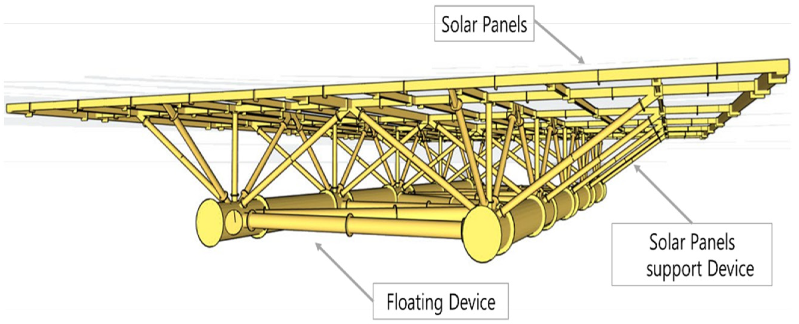
Figure 1. Floating structure model concept.
Energies 18 06019 g001
Figure 2. 0.5 MW floating structure model specification. (a) Specifications [12], (b) Front view, (c) Side view.
Energies 18 06019 g002aEnergies 18 06019 g002b
Figure 3. General flowchart of the proposed approach for standardization and modularization of floating offshore PV structures.
Energies 18 06019 g003
Figure 4. 0.5 MW floating device model welding position.
Energies 18 06019 g004
Figure 5. 0.5 MW Floating device model Comparison.
Energies 18 06019 g005aEnergies 18 06019 g005b
Figure 6. Container specifications.
Energies 18 06019 g006
Table 1. Specifications and functions of the floating device members.
NameSpecifications (mm)QuantityFunction
Main HullØ1500~2200 × 58,0002Acts as the main component of the platform, providing buoyancy and load support, protecting the structure from external environments, and reducing fluid resistance serving a critical role in environmental adaptability.
Diagonal BracingØ500~900 × 18,0005Functions as a reinforcement member connecting the two hulls and enhancing resistance to horizontal loads. It distributes external forces from marine environmental loads such as waves, currents, and wind, and controls relative movement between hulls to prevent fatigue damage.
Horizontal Bracing Ø650~1050 × 18,0004
ColumnØ200~450 × 373010Distributes the load of photovoltaic panels and supports the panels in conjunction with the floating structure. These vertical and diagonal columns are firmly attached to the hull and vary in length depending on site wave height. They serve to evenly distribute loads across the frame, reducing torsion and bending, preventing deformation and structural failure, and enhancing overall safety.
Diagonal ColumnØ200~450 × 8385
(Ø200~450 × 5820)
20
(20)
Table 2. Standardization and modularization strategies and effects.
CategoryStandardization and Modularization Measures
StrategyDesign TechnicalStandardized DesignEstablishment of standard structural dimensions
Modular DesignDesign considering on–site assembly and transportation
EffectAssembly & InstallationOn–site Assembly SystemFast assembly time, modular connections
Improved Maintenance AccessibilityModular structure for easy repair
Economic & LogisticsCost EfficiencySimplified modules suitable for mass production and standard transport methods
Localization StrategySimplified modules and joints for local labor and equipment sourcing
Table 3. Standardization and modularization content by member.
ClassificationMember Number and LengthNotes
Before ModularizationAfter Modularization
Pontoon1 Type, 1 ea–59,600 mm1 Type, 8 ea–8650 mm
Node2 Type, 10 ea–5000 mm
Standardization
Standardized with length adjustment
Horizontal Brace2 Type1 TypeStandardized with node flange joints
Diagonal Brace2 Type1 Type
Total Type5 Type5 Type
Table 4. Quantity of materials required for a single 0.5 MW installation.
ClassificationTotal Length (mm)Element Length (mm)Quantity (a)VolumeElement Length
Number of Splits (b)
Quantity
(a × b = c)
Width (mm)Height (mm)Length (mm)
Pontoon69,2008650818001800865018
Node 115,0005000318002550500013
Node 225,0005000518002580500015
Node 3–150005000118002580500011
Node 3–250005000118002580500011
Horizontal Brace74,60014,92059209207460210
Diagonal Brace76,48019,120410701070956028
Table 5. Number of containers required for a single 0.5 MW installation.
ClassificationWidth (mm)Height (mm)Length (mm)Quantity
(a × b = c)
Members per
Container
No. of Containers
(1 Unit)
Pontoon180018008650919
Node 1180025505000322
Node 2180025805000523
Node 3–1180025805000121
Node 3–2180025805000121
Horizontal Brace92092074601043
Diagonal Brace107010709560842
Total (for mixed loads)21 (19)
Table 6. Estimating transportation costs.
ClassificationUnitTugboat TransportContainer TransportNote
Distancekm46004600Busan–Jakarta
Speedkm/h9.3
Total Durationdays2013
Daily Operation CostUSD20,0003000Based on 4500 horsepower
Number of ContainersEA19
Total Transport CostUSD400,00057,000
Assembly Labor CostUSD3606 workers × 3 days × USD20
Lifting Equipment CostUSD9000~USD 3000/day, 200-ton crane
Total Cost400,00066,36066,360/400,000 = 0.17
Normalized Logistics CAPEX$/MW800,000132,720Assuming 0.5 MW system
Savings$/MW 667.28
(≈83%)
Compared to tugboat
Table 7. Sensitivity analysis for logistics cost (Container vs. Tugboat).
ScenarioContainer FreightLaborContainer Total (USD)Tugboat Fuel Share (α)Tugboat Total (USD)Container % of Tugboat
Low container vs. High tugboat−20%−10%54,9240.5 (+15%)430,00012.80%
Base vs. Base0%0%66,360400,00016.60%
High container vs. Low tugboat20%10%77,7960.5 (−15%)370,00021.00%
Table 8. Comparison of Construction Schedule between Tugboat and Container Transportation.
ClassificationUnitTugboat TransportContainer TransportNote
per Unitdays203.8–4.2Based on N = 19, p = 2 teams
Days per MWdays/MW407.6–8.4Extrapolated to 1 MW system
Disclaimer/Publisher’s Note: The statements, opinions and data contained in all publications are solely those of the individual author(s) and contributor(s) and not of MDPI and/or the editor(s). MDPI and/or the editor(s) disclaim responsibility for any injury to people or property resulting from any ideas, methods, instructions or products referred to in the content.