Standardization and Modularization Strategy for the Structures of Floating Offshore Solar Power Systems
Abstract
1. Introduction
2. Floating Marine Photovoltaic System Model
2.1. Floating Structure Model Concept
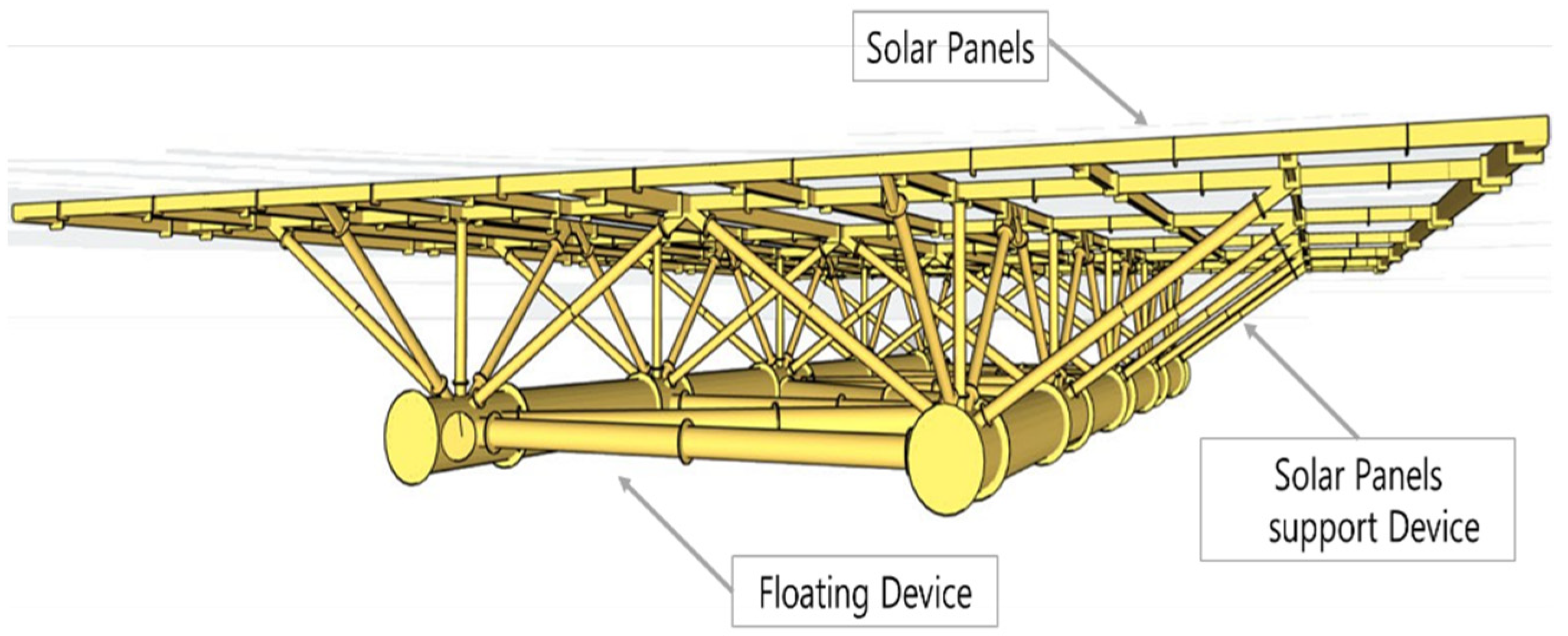
- A floating platform formed by two tubular hulls in a catamaran configuration.
- Solar panels are securely attached to the floating platform via robust support structures.
- Sufficient air gap (distance above the maximum water level) is maintained to minimize direct wave impact on the solar panels.
2.2. Floating Structure Model for Modularization and Standardization
3. Standardization and Modularization
3.1. Standardization and Modularization Strategy
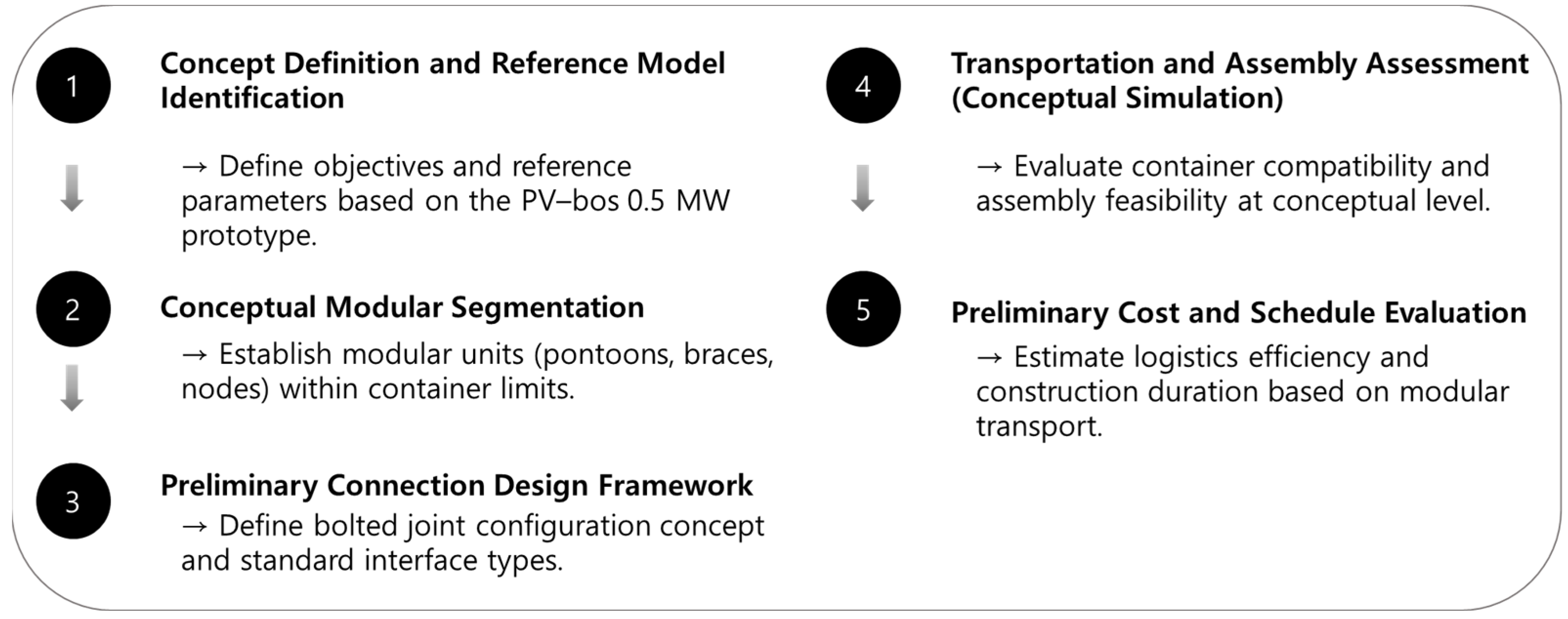
- Technical Design Strategy: Establish standard dimensions for structural components considering production and transportation conditions (within 2.6 m × 12 m). Components are selected and divided to enable repetitive production within these dimensions. Module dimensions and shapes are selected, and connection structures are designed for easy transportation and onsite assembly.
- Assembly and Installation Efficiency: Through design approaches that prioritize ease of onsite assembly, the floating device can be constructed quickly and accurately. The modular components are interconnected using bolt connections, employing techniques such as Poka–yoke methods and double bolting from inside and outside to avoid the need for specialized equipment or highly skilled personnel. This minimizes human errors and enhances operational efficiency and reliability. Moreover, modular components are independently designed, enabling quick replacement or repair of specific modules in case of failures or aging. Standardized components allow consistent global availability, reducing inventory risks and maintenance costs, and improving overall system stability and sustainability.
- Economic and Logistical Benefits: Simplified modular forms suitable for mass production enhance productivity, shorten construction periods, and improve economic viability. The modular structure facilitates standard maritime container transportation, significantly reducing transportation costs. Additionally, bolted connections make the system adaptable to specific local conditions, such as in Southeast Asia, particularly Indonesia, where specialized environmental and policy considerations exist. This eliminates the need for specialized equipment or personnel for module connections, thereby enabling tailored logistics strategies, ultimately reducing overall logistics costs.
3.2. Component Segmentation for Standardization and Modularization
3.2.1. Component Segmentation of the Basic Model
3.2.2. Review of Structural Member Connections for Modularization
3.3. Review of Transportation Efficiency for Standardized and Modular Members
3.3.1. Review of Transportation of Segmented Components Using Containers
3.3.2. Cost Review for Container Transportation
- Days per unit = N × (t_port + t)/p = 19 × (0.15 + 0.25)/2 = 3.8–4.2 days.
- Days per MW = 7.6–8.4 days/MW.
3.3.3. Sensitivity to Market Fluctuations
- Container totals vary only with ocean–freight and labor; lifting equipment kept at USD 9000.
- Tugboat total varies with fuel via ; table uses α = 0.5 as a representative case.
- For normalized logistics CAPEX ($/MW), multiply each “Total” by 2 (0.5 MW system). Thus, container ranges 109,848–155,592 $/MW, tugboat ranges 740,000–860,000 $/MW for α = 0.5.
4. Results and Discussion
5. Conclusions
Author Contributions
Funding
Data Availability Statement
Conflicts of Interest
Abbreviations
| Symbol/Acronym | Definition |
| PV | Photovoltaic |
| FEA | Finite Element Analysis |
| FRP | Fiber-Reinforced Polymer |
| CAPEX | Capital Expenditure |
| O&G | Oil and Gas |
| HC | High Cube |
| DV | Dry Van |
| MW | Megawatt |
| kWp | Kilowatt-peak |
| t_port | Average port handling time per container (days) |
| t | Average on-site assembly time per container (days) |
| p | Number of assembly teams |
| N | Number of containers per unit |
| α | Fuel cost share in tugboat operation |
| USD | United States Dollar |
References
- Djalab, A.; Djalab, Z.; El Hammoumi, A.; Tina, G.M.; Motahhir, S.; Laouid, A.A. A comprehensive Review of Floating Photovoltaic Systems: Tech Advances, Marine Environmental Influences on Offshore PV Systems, and Economic Feasibility Analysis. Sol. Energy 2024, 277, 112711. [Google Scholar] [CrossRef]
- Ren21. Renewables 2019 Global Status Report. 2019. Available online: https://www.ren21.net/ (accessed on 12 November 2025).
- El Hammoumi, A.; Chalh, A.; Allouhi, A.; Motahhir, S.; El Ghzizal, A.; Derouich, A. Design and construction of a test bench to investigate the potential of floating PV systems. J. Clean. Prod. 2021, 278, 123917. [Google Scholar] [CrossRef]
- Kabir, E.; Kumar, P.; Kumar, S.; Adelodun, A.A.; Kim, K.-H. Solar energy: Potential and future prospects. Renew. Sustain. Energy Rev. 2018, 82, 894–900. [Google Scholar] [CrossRef]
- Sreenath, S.; Sudhakar, K.; Af, Y. 7E analysis of a conceptual utility–scale land–based solar photovoltaic power plant. Energy 2021, 219, 119610. [Google Scholar] [CrossRef]
- Teo, J.C.; Tan, R.H.G.; Mok, V.H.; Ramachandaramurthy, V.K.; Tan, C. Impact of Partial Shading on the P–V Characteristics and the Maximum Power of a Photovoltaic String. Energies 2018, 11, 1860. [Google Scholar] [CrossRef]
- Zitouni, H.; Azouzoute, A.; Hajjaj, C.; El Ydrissi, M.; Regragui, M.; Polo, J.; Oufadel, A.; Bouaichi, A.; Ghennioui, A. Experimental investigation and modeling of photovoltaic soiling loss as a function of environmental variables: A case study of semi–arid climate. Sol. Energy Mater. Sol. Cells 2021, 221, 110874. [Google Scholar] [CrossRef]
- Claus, R.; López, M. Key issues in the design of floating photovoltaic structures for the marine environment. Renew. Sustain. Energy Rev. 2022, 164, 112502. [Google Scholar] [CrossRef]
- Yoon, S.J.; Joo, H.J.; Kim, S.H. Structural analysis and design for the development of floating photovoltaic energy generation system. Mater. Sci. Eng. 2018, 372, 12021. [Google Scholar] [CrossRef]
- Choi, J.-W.; Joo, H.-J.; Nam, J.-H.; Hwang, S.-T.; Yoon, S.-J. Performance Enhancement of Floating PV Generation Structure Using FRP. Compos. Res. 2013, 26, 105–110. [Google Scholar] [CrossRef]
- Sahu, A.; Yadav, N.; Sudhakar, K. Floating photovoltaic power plant: A review. Renew. Sustain. Energy Rev. 2016, 66, 815–824. [Google Scholar] [CrossRef]
- BlueNewables. PV–bos: Offshore Photovoltaic Floating Platform; BlueNewables Technical Report; BlueNewables: Madrid, Spain, 2018. [Google Scholar]
- Baniya, J.; Dai, J.; Jiang, Z.; Zhang, C. Numerical study of soft-connected modular offshore floating photovoltaic array. Mar. Struct. 2025, 104, 103893. [Google Scholar] [CrossRef]
- Yuan, Z.-M.; Yu, S.-R.; Incecik, A. A New Web-Type Concept of Floating Photovoltaic Farms in Open Sea Environment. Engineering 2025. [Google Scholar] [CrossRef]
- Amer, A.; Attar, H.; As’ad, S.; Alsaqoor, S.; Colak, I.; Alahmer, A.; Alali, M.; Borowski, G.; Hmada, M.; Solyman, A. Floating Photovoltaics: Assessing the Potential, Advantages, and Challenges of Harnessing Solar Energy on Water Bodies. J. Ecol. Eng. 2023, 24, 324–339. [Google Scholar] [CrossRef]
- DNV-OS-C101; Design of Offshore Steel Structures, General (LRFD Method). DNV: Høvik, Norway, 2019.
- ISO 19902; Fixed Steel Offshore Structures. International Organization for Standardization: Geneva, Switzerland, 2020.
- AISC 360-16; Specification for Structural Steel Buildings. American Institute of Steel Construction: Chicago, IL, USA, 2016.
- EN 1993-1-8; Eurocode 3—Design of Steel Structures—Part 1-8: Design of Joints. European Committee for Standardization (CEN): Brussels, Belgium, 2005.
- DNVGL-RP-C203; Fatigue Design of Offshore Steel Structures. DNV GL: Høvik, Norway, 2016.
- BlueNewables. Flanges and Joints Typologies Report; BlueNewables: Madrid, Spain, 2025. [Google Scholar]
- Ţălu, Ş.; Yadav, P.R.; Šik, O.; Sobola, D.; Dallaev, R.; Solaymani, S.; Man, O. How topographical surface parameters are correlated with CdTe monocrystal surface oxidation. Mater. Sci. Semicond. Process. 2018, 85, 15–23. [Google Scholar] [CrossRef]
- Werner, F.; Veith-Wolf, B.; Spindler, C.; Barget, M.R.; Babbe, F.; Guillot, J.; Schmidt, J.; Siebentritt, S. Oxidation as Key Mechanism for Efficient Interface Passivation in Cu(In,Ga)Se2 Thin-Film Solar Cells. Phys. Rev. Appl. 2020, 13, 054004. [Google Scholar] [CrossRef]
- ISO 668:2020; Series 1 Freight Containers Classification, Dimensions and Ratings. ISO: Geneva, Switzerland, 2020.
- Hwang Sung–Hyun. Escort Booking Management, Korea Pilotage Association. 2006. Available online: https://kmpilot.or.kr (accessed on 12 November 2025).
- Tugboat Usage Rates. Available online: http://www.busantug.kr/sub02/sub03_01.php (accessed on 8 April 2025).
- Ocean Container Logistics Costs. Available online: https://www.tradlinx.com (accessed on 8 April 2025).
- Indonesia Labor Market Trends, Ministry of Foreign Affairs. 2024. Available online: https://gbr.mofa.go.kr/ (accessed on 12 November 2025).
- Crawler Crane Rental Rates in Indonesia. Available online: https://blog.naver.com/babotak/223322738823 (accessed on 8 April 2025).



| Name | Specifications (mm) | Quantity | Function |
|---|---|---|---|
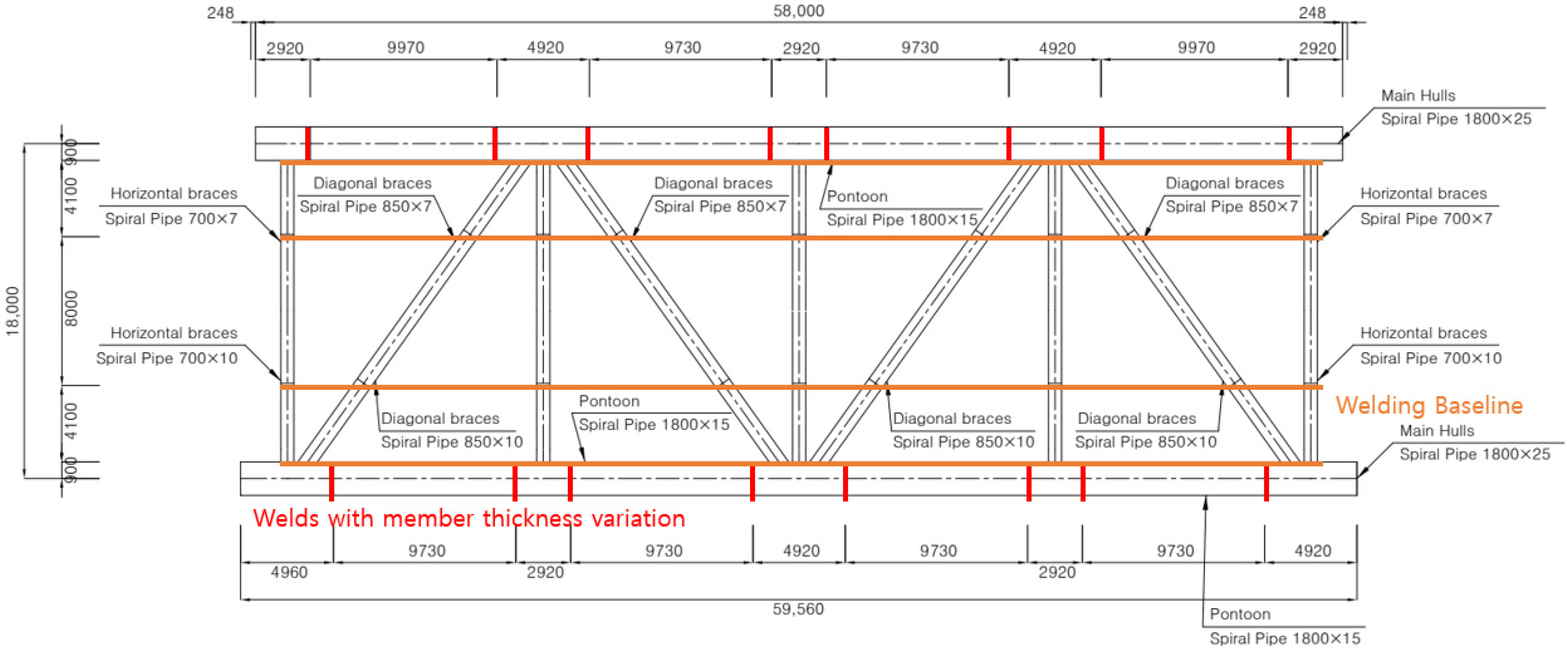
| Main Hull | Ø1500~2200 × 58,000 | 2 | Acts as the main component of the platform, providing buoyancy and load support, protecting the structure from external environments, and reducing fluid resistance serving a critical role in environmental adaptability. |
| Diagonal Bracing | Ø500~900 × 18,000 | 5 | Functions as a reinforcement member connecting the two hulls and enhancing resistance to horizontal loads. It distributes external forces from marine environmental loads such as waves, currents, and wind, and controls relative movement between hulls to prevent fatigue damage. |
| Horizontal Bracing | Ø650~1050 × 18,000 | 4 | |
| Column | Ø200~450 × 3730 | 10 | Distributes the load of photovoltaic panels and supports the panels in conjunction with the floating structure. These vertical and diagonal columns are firmly attached to the hull and vary in length depending on site wave height. They serve to evenly distribute loads across the frame, reducing torsion and bending, preventing deformation and structural failure, and enhancing overall safety. |
| Diagonal Column | Ø200~450 × 8385 (Ø200~450 × 5820) | 20 (20) |
| Category | Standardization and Modularization Measures | ||
|---|---|---|---|
| Strategy | Design Technical | Standardized Design | Establishment of standard structural dimensions |
| Modular Design | Design considering on–site assembly and transportation | ||
| Effect | Assembly & Installation | On–site Assembly System | Fast assembly time, modular connections |
| Improved Maintenance Accessibility | Modular structure for easy repair | ||
| Economic & Logistics | Cost Efficiency | Simplified modules suitable for mass production and standard transport methods | |
| Localization Strategy | Simplified modules and joints for local labor and equipment sourcing | ||
| Classification | Member Number and Length | Notes | |
|---|---|---|---|
| Before Modularization | After Modularization | ||
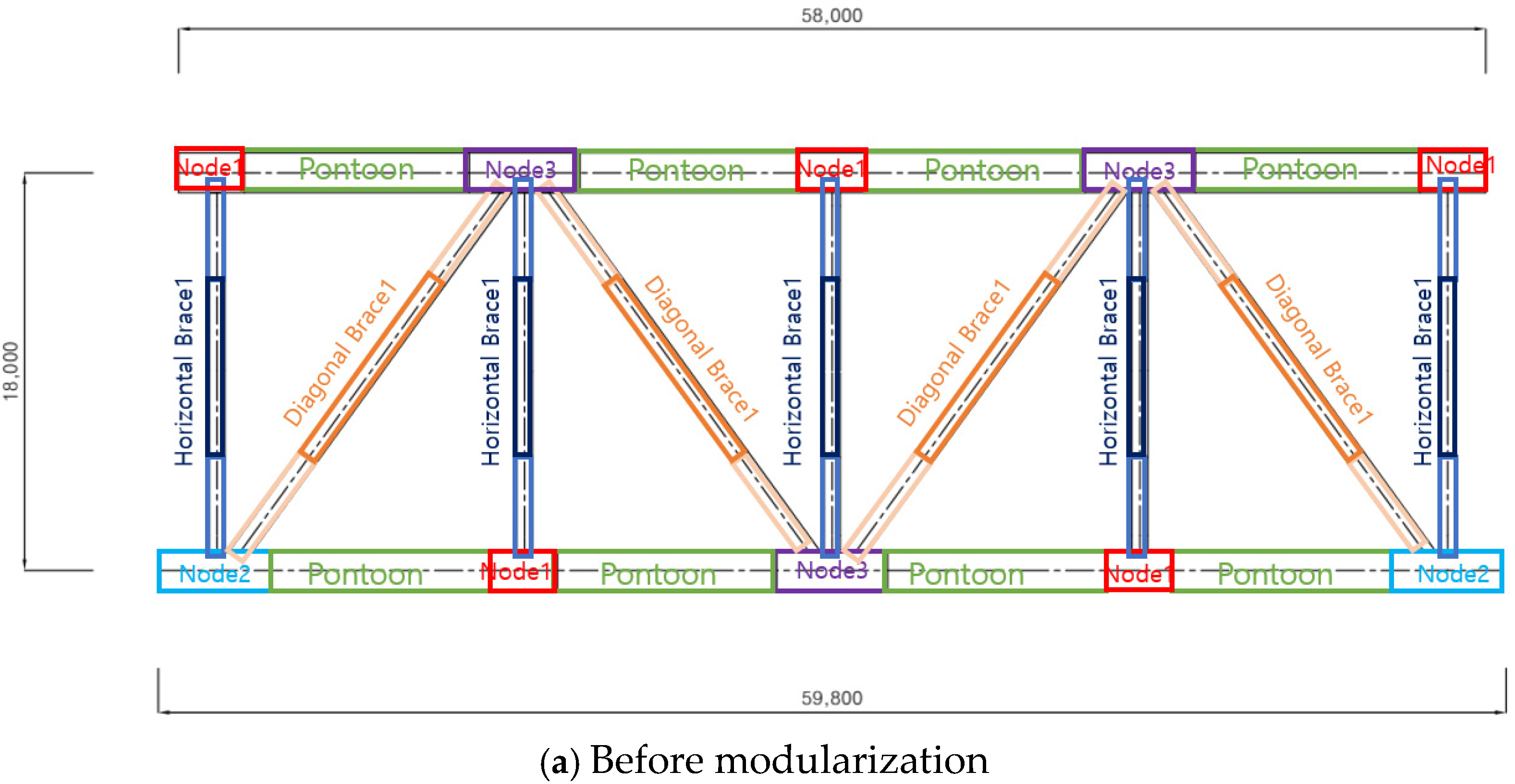
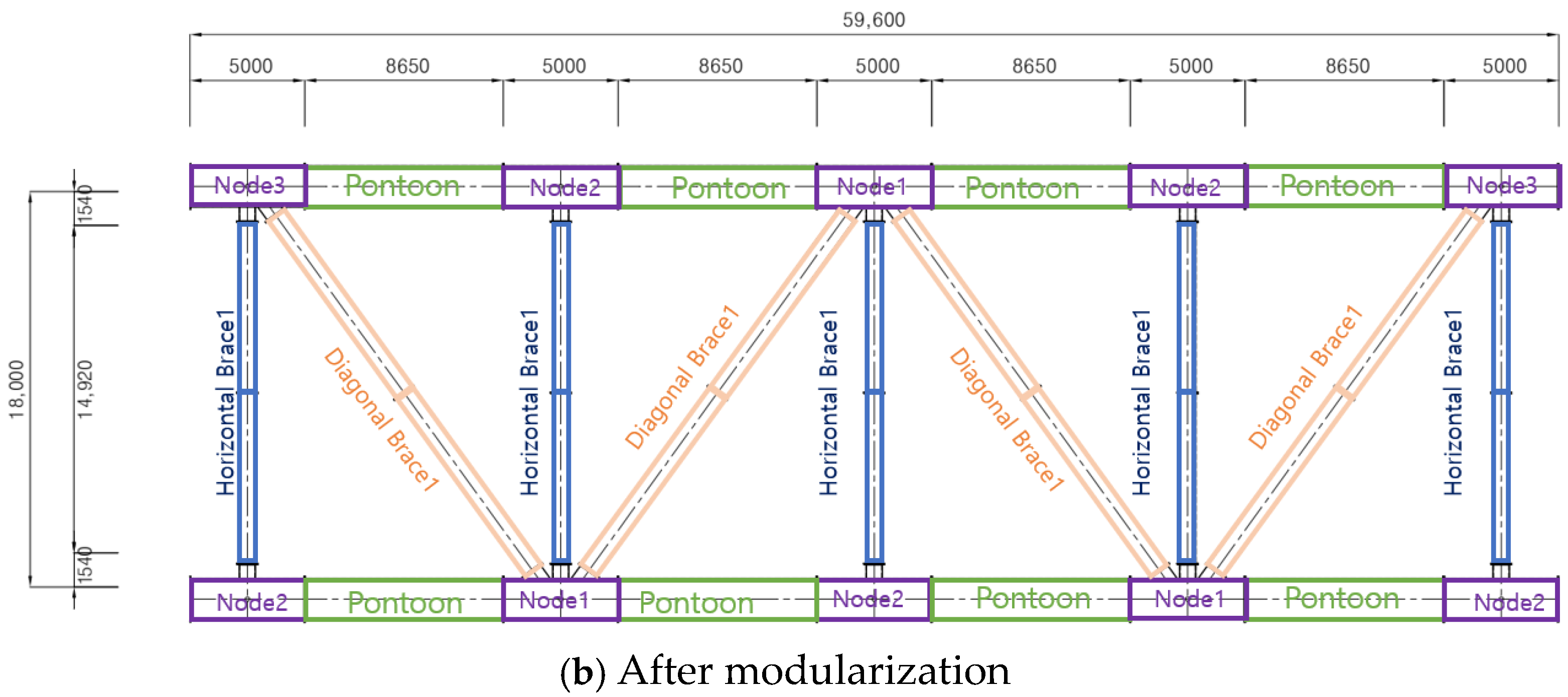
| Pontoon | 1 Type, 1 ea–59,600 mm | 1 Type, 8 ea–8650 mm | |
| Node | – | 2 Type, 10 ea–5000 mm Standardization | Standardized with length adjustment |
| Horizontal Brace | 2 Type | 1 Type | Standardized with node flange joints |
| Diagonal Brace | 2 Type | 1 Type | |
| Total Type | 5 Type | 5 Type | |
| Classification | Total Length (mm) | Element Length (mm) | Quantity (a) | Volume | Element Length Number of Splits (b) | Quantity (a × b = c) | ||
|---|---|---|---|---|---|---|---|---|
| Width (mm) | Height (mm) | Length (mm) | ||||||
| Pontoon | 69,200 | 8650 | 8 | 1800 | 1800 | 8650 | 1 | 8 |
| Node 1 | 15,000 | 5000 | 3 | 1800 | 2550 | 5000 | 1 | 3 |
| Node 2 | 25,000 | 5000 | 5 | 1800 | 2580 | 5000 | 1 | 5 |
| Node 3–1 | 5000 | 5000 | 1 | 1800 | 2580 | 5000 | 1 | 1 |
| Node 3–2 | 5000 | 5000 | 1 | 1800 | 2580 | 5000 | 1 | 1 |
| Horizontal Brace | 74,600 | 14,920 | 5 | 920 | 920 | 7460 | 2 | 10 |
| Diagonal Brace | 76,480 | 19,120 | 4 | 1070 | 1070 | 9560 | 2 | 8 |
| Classification | Width (mm) | Height (mm) | Length (mm) | Quantity (a × b = c) | Members per Container | No. of Containers (1 Unit) |
|---|---|---|---|---|---|---|
| Pontoon | 1800 | 1800 | 8650 | 9 | 1 | 9 |
| Node 1 | 1800 | 2550 | 5000 | 3 | 2 | 2 |
| Node 2 | 1800 | 2580 | 5000 | 5 | 2 | 3 |
| Node 3–1 | 1800 | 2580 | 5000 | 1 | 2 | 1 |
| Node 3–2 | 1800 | 2580 | 5000 | 1 | 2 | 1 |
| Horizontal Brace | 920 | 920 | 7460 | 10 | 4 | 3 |
| Diagonal Brace | 1070 | 1070 | 9560 | 8 | 4 | 2 |
| Total (for mixed loads) | 21 (19) | |||||
| Classification | Unit | Tugboat Transport | Container Transport | Note |
|---|---|---|---|---|
| Distance | km | 4600 | 4600 | Busan–Jakarta |
| Speed | km/h | 9.3 | – | |
| Total Duration | days | 20 | 13 | |
| Daily Operation Cost | USD | 20,000 | 3000 | Based on 4500 horsepower |
| Number of Containers | EA | – | 19 | |
| Total Transport Cost | USD | 400,000 | 57,000 | |
| Assembly Labor Cost | USD | – | 360 | 6 workers × 3 days × USD20 |
| Lifting Equipment Cost | USD | – | 9000 | ~USD 3000/day, 200-ton crane |
| Total Cost | 400,000 | 66,360 | 66,360/400,000 = 0.17 | |
| Normalized Logistics CAPEX | $/MW | 800,000 | 132,720 | Assuming 0.5 MW system |
| Savings | $/MW | 667.28 (≈83%) | Compared to tugboat | |
| Scenario | Container Freight | Labor | Container Total (USD) | Tugboat Fuel Share (α) | Tugboat Total (USD) | Container % of Tugboat |
|---|---|---|---|---|---|---|
| Low container vs. High tugboat | −20% | −10% | 54,924 | 0.5 (+15%) | 430,000 | 12.80% |
| Base vs. Base | 0% | 0% | 66,360 | — | 400,000 | 16.60% |
| High container vs. Low tugboat | 20% | 10% | 77,796 | 0.5 (−15%) | 370,000 | 21.00% |
| Classification | Unit | Tugboat Transport | Container Transport | Note |
|---|---|---|---|---|
| per Unit | days | 20 | 3.8–4.2 | Based on N = 19, p = 2 teams |
| Days per MW | days/MW | 40 | 7.6–8.4 | Extrapolated to 1 MW system |
Disclaimer/Publisher’s Note: The statements, opinions and data contained in all publications are solely those of the individual author(s) and contributor(s) and not of MDPI and/or the editor(s). MDPI and/or the editor(s) disclaim responsibility for any injury to people or property resulting from any ideas, methods, instructions or products referred to in the content. |
© 2025 by the authors. Licensee MDPI, Basel, Switzerland. This article is an open access article distributed under the terms and conditions of the Creative Commons Attribution (CC BY) license (https://creativecommons.org/licenses/by/4.0/).
Share and Cite
Lee, K.; Kim, M.; Esteve, A.; Sainz, O. Standardization and Modularization Strategy for the Structures of Floating Offshore Solar Power Systems. Energies 2025, 18, 6019. https://doi.org/10.3390/en18226019
Lee K, Kim M, Esteve A, Sainz O. Standardization and Modularization Strategy for the Structures of Floating Offshore Solar Power Systems. Energies. 2025; 18(22):6019. https://doi.org/10.3390/en18226019
Chicago/Turabian StyleLee, Kyusuk, Moonok Kim, Alfredo Esteve, and Oscar Sainz. 2025. "Standardization and Modularization Strategy for the Structures of Floating Offshore Solar Power Systems" Energies 18, no. 22: 6019. https://doi.org/10.3390/en18226019
APA StyleLee, K., Kim, M., Esteve, A., & Sainz, O. (2025). Standardization and Modularization Strategy for the Structures of Floating Offshore Solar Power Systems. Energies, 18(22), 6019. https://doi.org/10.3390/en18226019


