Abstract
The ocean offers abundant wind and wave energy resources. This paper proposes an integrated concept that co-locates a semi-submersible floating wind platform with wave energy converters (WECs) to exploit the geographical consistency of these resources. By sharing the platform foundation and power transmission infrastructure, this integrated system enhances the utilization efficiency of marine space and renewable energy. Inspired by the principles of the Tuned Mass Damper (TMD) and leveraging mature hydraulic technologies from wave energy conversion and offshore drilling heave compensation systems, this study introduces a novel scheme. This scheme integrates a heave plate with a hydraulic Power Take-Off (PTO) system, functionally acting as a wave energy converter, to the floating platform. The primary objective is to mitigate the platform’s motion response while simultaneously generating electricity. The research investigates the motion performance improvement of this integrated platform under South China Sea conditions. The results demonstrate that the proposed WEC–PTO system not only improves the platform’s wave resistance and adaptability to deep-sea environments but also increases the overall efficiency of marine energy equipment deployment.
1. Introduction
With the rapid development of offshore wind power generation, the concept of wind and wave energy integrated power generation structures has been proposed in recent years. This type of integrated wind and wave energy power generation structure mainly leverages the high geographical correlation between wind and wave energy. In the field of integrated structure research, the Marine Renewable Integrated Application Platform program launched by the European Commission began relatively early. Among these efforts, Moan et al. from the Norwegian University of Science and Technology proposed a wind–wave energy integrated structure, namely the Spar–Torus Combination (STC) [1,2,3,4,5,6], in 2012, as shown in Figure 1a. The STC is composed of a circular float surrounding the column of a Spar-type floating wind turbine.
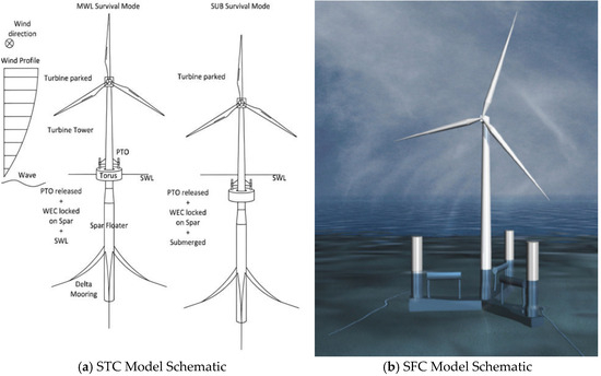
Figure 1.
Schematic Diagrams of STC and SFC Models.
The wave force causes the float and the column to produce relative heaving motion, thus driving the hydraulic PTO system to generate electricity. This structure is suitable for installation in deep-sea areas. However, due to both its high construction cost and the small phase difference between the motion of the wave energy device and that of the platform, the power generation capacity of the wave energy device remains significantly limited.
Moan’s team also proposed the Semi-submersible-Flap Combination (SFC) structure [7,8,9,10] in 2014, as shown in Figure 1b. The SFC connects three pendulum wave energy devices to the bottom of CSC type semi-submersible platform. The wind turbine is located in the central tower column, and the platform obtains restoring moments from the three offset columns. Compared with the STC, the wave energy device of the SFC can generate more electricity, but at the same time, it transfers part of the horizontal wave load to the platform.
Ren et al. (2018) proposed a wind–wave energy integrated power generation structure based on a Tension Leg Platform (TLP)-type platform [11,12], as shown in Figure 2. This structure is based on the principle of an oscillating float-type wave energy device. When waves come, it enables the platform and the wave energy device to generate relative motion in the heaving direction, thus driving the PTO system to generate electricity. Its pulley and slide structure ensures that the wave energy device does not produce relative motion in other degrees of freedom. This endows the integrated device with better stability, and the output power of the wave energy device is larger compared with that of the STC and SFC.
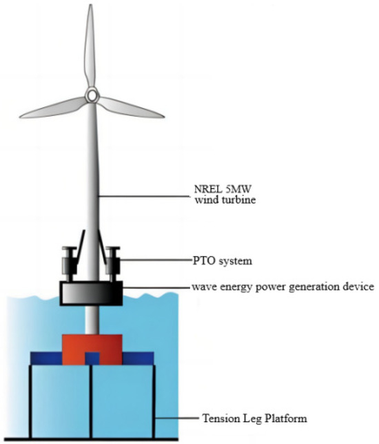
Figure 2.
TLP-type platform and WEC integrated structure.
Hu et al. (2020) proposed to arrange several point-absorbing wave energy converters between the pontoons of the platform [13], as shown in Figure 3. They study the power generation performance of wave energy converters with different sizes and layouts, as well as their effects on the platform’s hydrodynamic characteristics. In this integrated system, the higher the damping of the wave energy devices, the greater the power generation. However, at the same time, the heaving force acting on the platform also increases.
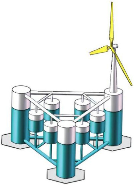
Figure 3.
Semi-submersible platform and heaving WEC integrated structure.
Wang Yapo (2021) carried out frequency and time domain analyses of the hydrodynamic response of the platform based on the integrated structure of the CSC type semi-submersible platform under different wave incidence angles, obtained the hydrodynamic characteristics of the platform after integrating the PTO system, and investigated the power generated by the PTO system with different damping values [14]. The structure of the integrated system and the working principle of the PTO system are shown in Figure 4a and Figure 4b, respectively.
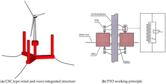
Figure 4.
CSC type semi-submersible platform and wave energy integrated structure.
Wang Yu (2021) conducted a study on the influence of different PTO damping values on the power output of the PTO system of the pontoon-heaving float integrated structure under regular and irregular waves [15]. The pontoon structure is shown in Figure 5.
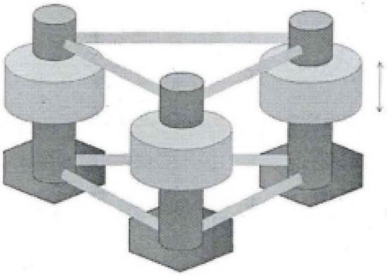
Figure 5.
Pontoon-heaving float integrated structure.
In 2021 and 2022, respectively, Ghafari et al. proposed the structure Floating Offshore Wind Turbine-WaveStar (FOWT-WaveStar) [16,17,18], which combines the DeepCwind type and CSC type semi-submersible platforms, as shown in Figure 6a,b. They summarized the characteristics of several existing wave energy–wind energy integrated structures, calculated the power of the PTO system for different numbers of wave devices and power generation damping values, and investigated the effects of wave energy devices on the heaving and pitching performances of the platform. Additionally, they compared these performances with those of semi-submersible platforms without integrated wave energy devices in both the time domain and frequency domain under regular waves. The results show that the power generation efficiency of the wave energy devices mainly depends on the damping coefficient. Deploying more WaveStar devices can improve the platform’s pitching performance to a certain extent, but has little effect on improving other degrees of freedom.
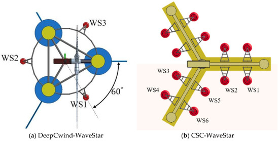
Figure 6.
FOWT-Wavestar Structure.
Homayoun et al. (2022) proposed another wave energy converter structure, the Semi-submersible Wave–Wind Converter (SWWC), installed on the CSC type semi-submersible platform [19], as shown in Figure 7. They investigated the Response Amplitude Operators (RAOs): the ratio of a floating structure’s motion amplitude to the incident wave amplitude, reflecting the structure’s dynamic response sensitivity to waves of the platform for each degree of freedom under different wave and wind directions. Moreover, they considered the hydrodynamic effects on the platform caused by three sea states and three different PTO system damping values, and calculated the power generated by the PTO system under ideal wave conditions.
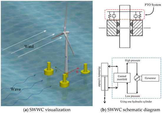
Figure 7.
SWWC Structure Model.
Zhou et al. (2023) conducted a study on the influence of different wave energy device damping on platform resonance for STC structures, taking different mooring stiffnesses into account [20]. They proposed an integrated system (HWEC) based on a Windfloat platform and an arbitrary number of cylindrical wave energy arrays, and investigated the hydrodynamic performance of the platform with different numbers and arrangements of wave energy devices in this integrated system. In the same year, a numerical model was proposed for this structure to study the impact of HWEC on the mooring system and platform foundation [21]. The results show that HWEC does not have a negative impact on the heaving and pitching motions of the platform main body caused by wind-induced surges, and that the HWEC can generate more than 500 kW of power to supplement wind power generation.
The integrated structure of wave energy-floating wind power platform proposed in recent years has, on the one hand, improved the economic efficiency of wave energy devices. On the other hand, the wave energy devices arranged around the periphery of the platform also play a certain role in wave dissipation. However, at present, the relevant research is still in the conceptual design stage, and the following problems remain:
- (1)
- All the related research focuses on power generation efficiency and the influence on platform movement in the case of the coupling between the wave energy device and the platform, and there are few cases of research specifically on its wave dissipation effect.
- (2)
- In the research related to vibration and roll reduction of platforms, there are few studies that consider different floating platforms, different heave plate structures, arrangement depths, and arrangement areas as variables for comparison at the same time. As a result, there is a lack of experience in the design and optimization of wave-energy and wind-energy integrated platforms with practical economic benefits.
The heaving performance of deep-sea platforms is one of the factors restricting marine operations. In this paper, by adding a heave plate structure as a vibration damping measure, the heaving performance of three types of floating platforms with different areas and arrangement depths of the heave plate is investigated. The platform structure with the greatest integrated benefit is selected, and the integrated oscillating float platform structure is proposed. The RAO computation method of the coupled model of the wave-energy and wind-energy integrated platform combined with the heave plate is introduced, and the improvement of platform motion under different PTO system stiffnesses is analyzed. In addition, in order to obtain the adaptability of the PTO stiffness to the sea conditions in the South China Sea, the motion performance of four different PTO stiffnesses under different sea states in the time domain is also studied.
2. Study on the Improvement of Hydrodynamic Performance of Semi-Submersible Platforms
Semi-submersible platforms have a wide range of applications. They are not only used as foundations for offshore floating wind turbines but also widely used for offshore oil and gas platforms. To identify an economically viable integrated structure, this study adopts the combination of a heave plate and a semi-submersible platform. Specifically, three types of semi-submersible platforms are selected as case studies for analysis. The DeepCwind type semi-submersible platform, developed by the National Renewable Energy Laboratory (NREL) in the United States, is one of the mainstream platforms for current offshore floating wind turbine systems. The other two are the CSC type semi-submersible platform released by Marintek (Trondheim, Norway) and more mature dual-pontoon and four-column semi-submersible platform. The models of these three types of platforms are shown in Figure 8.
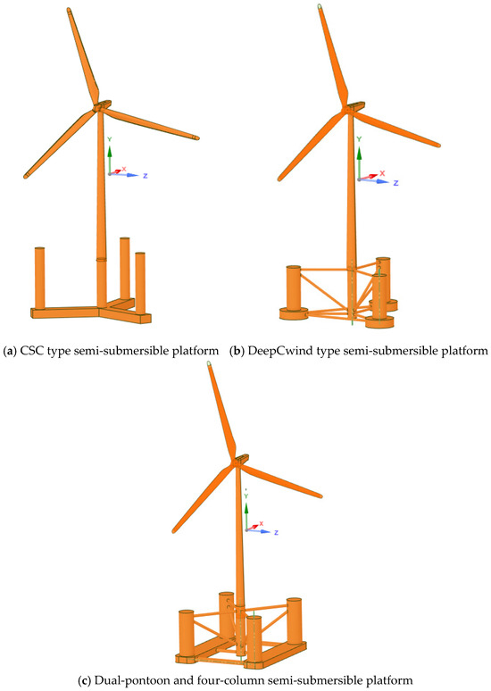
Figure 8.
Installation models of three types of floating platforms.
Heave plate structures can significantly increase the additional mass of a floating platform and provide radiation damping, thereby reducing the heaving response of the floating platform. Halkyard proposed adding a retractable heave plate structure to semi-submersible platforms, which can provide a greater heaving radiation force for the platform [22]. Moreover, some scholars have studied the influence of the size, thickness, number, and spacing of the heave plates, as well as the shape of the central opening of the heave plate on the drag force coefficient, additional mass coefficient, and heaving response of the heave plate, focusing on the damping effect of the heave plate [23,24,25,26,27,28].
This paper establishes hydrodynamic models with heave plates for three types of platforms, respectively. Considering the impacts of the heave plates on the structural mass, center of gravity, and moment of inertia, it conducts research on the heaving vibration damping effect of different semi-submersible platforms combined with heave plates.
2.1. Influence of the Depth of Heave Plate Arrangement on the Platform Motion
At present, heave plates are mainly used in Spar platforms. However, due to the deeper draught of the Spar platform, the corresponding depth of the heave plate arrangement is also greater. Thus, the wave-induced force on the heave plate, located hundreds of meters below the water surface, becomes negligible. For semi-submersible platforms, though, because of the relatively shallow draft of the platform main body, arranging the heave plate too deep increases the manufacturing cost.
To control these variables, the area of each added heave plate is set to 1000 m2. The influence of the drag force of the truss structure of each platform is ignored, and the Morison unit is not established for the trusses. Instead, the Discs unit is used to establish five models: models with the heave plates at depths of 30 m, 60 m, 90 m, 120 m underwater, respectively, and a model without a heave plate. The wave incidence direction is 0°. To enhance the tuning and damping effect of the integrated structure, a heave plate structure without holes is established. Figure 9 shows the grid model of each platform when the arrangement depth of the heave plate is 60 m. For the grid meshing of these models: unstructured tetrahedral grids are adopted to fit the complex structures of platform columns and heave plate trusses; local refinement is applied to wet surfaces (e.g., platform columns, heave plate) to ensure the accuracy of hydrodynamic calculations, while relatively coarser grids are used for non-wet structural parts to balance calculation precision and efficiency. All grids meet the quality requirements for marine hydrodynamic simulations, with skewness < 0.8 and aspect ratio < 5.
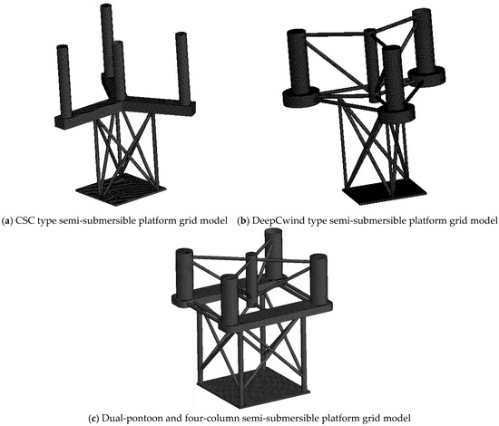
Figure 9.
Models of three types of floating platforms with a 60 m heave plate.
The heaving unit amplitude responses of the three types of platforms at different depths are shown in Figure 10, Figure 11 and Figure 12 below.
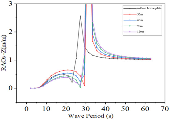
Figure 10.
RAO of CSC type semi-submersible platform with different depths of heave plates.
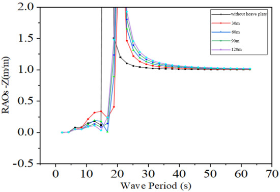
Figure 11.
RAO of DeepCwind type semi-submersible platform with different depths of heave plates.
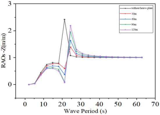
Figure 12.
RAO of dual-pontoon and four-column semi-submersible platform with different depths of heave plates.
From the results of hydrodynamic analysis, it can be seen that the deeper the heave plate structure is arranged, the greater the heaving response of each platform in certain intervals of high wave periods. However, in the low frequency band or the working frequency band, increasing the depth of the heave plate significantly reduces the heaving response of the platform. When the arrangement depth of the heave plates of the three types of platforms reaches 60 m, the heaving response of the platforms can be effectively reduced, and this result is generally consistent with Chen C Y et al.’s study [29].
Moreover, as the arrangement depth of the heave plates increases, the rate of improvement of the damping effect begins to slow down. The above phenomenon can be explained by the Airy wave theory. As the heave plate is arranged deeper, the wave-induced force acting on the heave plate decreases rapidly, and the restraining effect on the platform gradually increases. Once the wave-induced force approaches the radiation force provided by the platform’s motion, the effect of further increasing the arrangement depth of the heave plate starts to decrease.
When comparing the three types of platforms, arranging heave plates on the dual-pontoon and four-column semi-submersible platform yields the best results, and the heave plates play a positive role within the working frequency band.
2.2. Influence of the Area of Heave Plates on the Platform
Combined with the previous results, heave plates with areas of 600 m2, 1200 m2, 1800 m2, and 2400 m2 were added to the three types of platforms at a depth of 60 m underwater, as shown in Figure 13, Figure 14 and Figure 15.
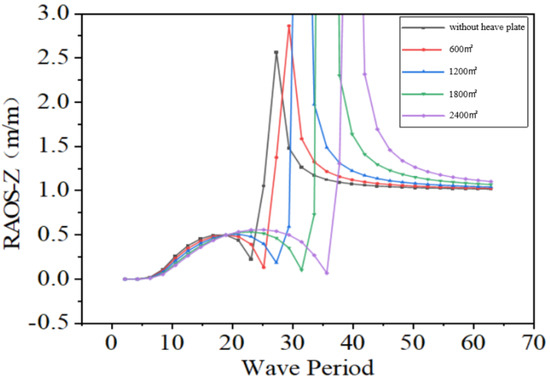
Figure 13.
RAO of CSC type semi-submersible platform with different heave plate areas.

Figure 14.
RAO of DeepCwind type semi-submersible platform with different heave plate areas.
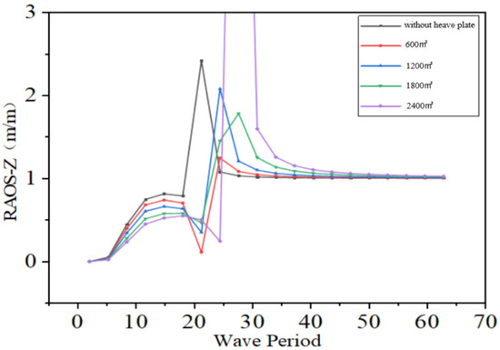
Figure 15.
RAO of dual-pontoon and four-column semi-submersible platform with different heave plate areas.
The above results indicate that within the working cycle, increasing the area of the heave plates has an insignificant effect on both CSC type semi-submersible platform and DeepCwind type semi-submersible platform. However, under severe sea conditions, the heave plates actually increase the heaving response. For the dual-pontoon and four-column semi-submersible platform, the effect of increasing the area of the heave plates is relatively uniform up to 1200 m2, but it starts to decline after approaching 1800 m2. Moreover, a larger area of the heave plate leads to a significant increase in the complexity of the truss structure. When compared with the three types of platforms, increasing the area of the heave plates for the dual-pontoon and four-column semi-submersible platform is more economically beneficial.
3. Oscillating Float-Type Wave Energy Device and Semi-Submersible Platform Integrated Structure Scheme
Since Frahm proposed the TMD, it has been widely applied in aerospace, construction, machinery, and other industries [30]. Structures prone to severe pitching and rolling (e.g., wind turbine nacelles) and super high-rise buildings (e.g., the Shanghai World Financial Center and Taipei 101) are equipped with TMD dampers. Ordinary TMDs dissipate energy in the form of heat during the energy absorption process. However, over the past decade, some scholars have replaced TMD devices with power generation structures, thereby achieving the goal of energy collection [31,32,33,34,35]. Among these efforts, Nerubenko et al. (2019) proposed using TMDs in conjunction with generators to reduce the dynamic load on ocean buoys [36].
In practical engineering, a large number of floating structures are constantly subjected to wave impact loads, which is detrimental to both the normal operation of personnel and the fatigue life of the platform. The hydraulic PTO system can be regarded as a power-generating TMD, as it exhibits damping during power generation and the spring within the hydraulic cylinder can provide restoring stiffness. If the hydraulic PTO system can be used rationally to absorb vibration energy for power generation, it will be possible to reduce platform rocking while harnessing wave energy.
3.1. Principle of Vibration Damping of the PTO System
If the setting depth of the heave plate is too large, it will drastically increase the cost; if it is too shallow, the desired effect will not be achieved. Based on the above conclusions, considering the aspects of cost and construction convenience, the heave plate is arranged at a depth of 60 m underwater. According to the position of the columns of the dual-pontoon and four-column semi-submersible platform, and for the convenience of arranging the truss structure, the area of the heave plate is selected to be 1200 m2.
Based on the principle of tuned damping, in forced vibration, the heaving period of the platform and the period of the incoming waves tend to be equal. Moreover, the wave-induced force acting on the underwater heave plate is much smaller than that at the water surface. This makes it possible to adjust the phase difference between the motion of the heave plate and that of the platform by adjusting the rigidity of the PTO system.
According to the reciprocating heaving motion of the platform, the hydraulic PTO system connects the floating platform and the heave plate. This not only reduces the motion of the platform but also captures a significant amount of wave energy. Due to the pitching, rolling, and other motions of the floating body in different degrees of freedom, multiple PTO systems are arranged at different positions to reduce the bending moment. Taking four PTO systems as an example, the PTO system is simplified into a spring-damping form, and the simplified structural model of the integrated platform is shown in Figure 16.
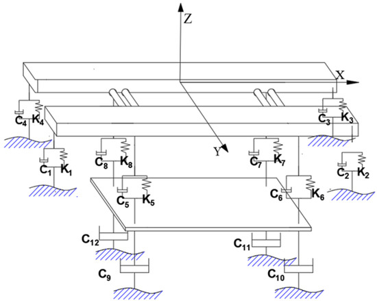
Figure 16.
Model diagram of wind-wave energy integration system.
The arrangement position and working mode of the hydraulic PTO system are shown in Figure 17. The PTO system connects the heave plate truss structure with the main body of the platform. For a stationary floating platform, the mass of the heave plate is balanced by its buoyancy, which has little impact on the structure. For a moving platform, the mass of the heave plate itself and the mass of the water it needs to drive will greatly reduce the platform’s motion response.
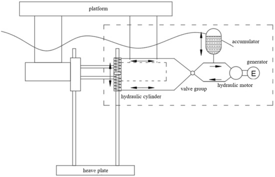
Figure 17.
Schematic of the Semi-Submersible Wind-Wave Energy Platform Integration System.
3.2. RAO Calculation Method for Semi-Submersible Platform with Integrated PTO System
If the coupling effect of motions in other directions is ignored, the heaving model of this integrated platform structure under a single PTO system can be further simplified. Figure 18a shows the traditional fixed heave plate platform model, and Figure 18b shows the model of the platform after it is connected to the heave plate by the PTO device. The numerical simulation method for the heaving response of the integrated platform is different from that for the response calculation of a platform with a fixed heave plate.
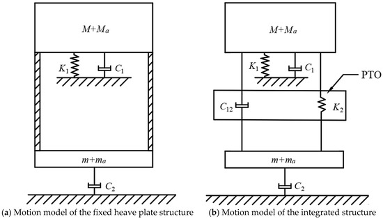
Figure 18.
Motion models of the traditional fixed heave plate platform and the integrated platform.
If and are used to denote the effective mass of the platform structure and the heave plate structure for numerical calculations, respectively, then the matrix form of the equations of motion of the system in the heaving direction is:
where:
—computational mass of the platform, which consists of the platform structure mass and the additional mass , i.e., ;
—computational mass of the heave plate, which consists of the heave plate structure mass and the additional mass , i.e., ;
—damping of the PTO system. Since its effect on the tuning frequency is small, the existence of damping is not considered for the time being, and is taken as 0;
—damping coefficient of the platform structure, including radiation damping and viscous damping , so ;
—damping coefficient of the heave plate structure, including radiation damping and viscous damping , so ;
—heaving hydrostatic restoring stiffness of the platform structure, which is proportional to the waterplane area of the platform;
—equivalent PTO system stiffness;
—heaving displacement of the platform structure;
—heaving displacement of the heave plate structure;
—vertical wave-induced force acting on the platform structure, which is determined by the lower wet surface of the platform and the water depth. It can be considered equal to the wave-induced force acting on a fixed floating platform;
—vertical wave-induced force acting on the heave plate structure, which is determined by the outer surface of the heave plate and the water depth. It can be considered equal to the wave-induced force acting on a fixed heave plate.
The effective mass, the total damping coefficient, and the vertical wave-induced forces and of the dual-pontoon and four-column semi-submersible platform structure and the heave plate structure used for numerical calculations can be calculated and determined based on the wet surface geometry of the platform and the geometry of the heave plate. The hydrostatic restoring stiffness of the platform is determined by the waterplane area of the platform columns. The viscous damping of the platform and the heave plate can be expressed as:
where:
—Amplitude of the vertical displacement of the floating platform;
—Amplitude of the vertical displacement of the heave plate;
—Vertical projected area of the wet surface of the platform;
—Vertical projected area of the heave plate.
Then, the wave-induced force in the vertical degree of freedom can be expressed as:
where:
—Amplitude of the vertical wave-induced force of the platform;
—Amplitude of the vertical wave-induced force of the heave plate.
If the viscous resistance of water is ignored, and assuming that the center of gravity of the heave plate and the center of gravity of the platform coincide in the vertical projection, the wave-induced force acting on the platform and the wave-induced force acting on the heave plate have the same frequency and phase. Define , , , , and as follows, respectively:
If the mass ratio of the heave plate to the platform, the ratio of the natural frequency of the heave plate to that of the platform, and the ratio of the incident wave frequency to the natural frequency of the platform are defined as follows, respectively:
Since the steady-state period is the same as the excitation period in forced vibration, and only the phase is different, the platform displacement and the heave plate displacement can be set as follows, respectively:
Thus, Equation (1) can be rewritten as:
If the additional mass coefficient is defined as follows:
Then, the solution to Equation (6) is:
Thus, the modulus of the amplitude of the heaving response of the platform body and the heave plate of this integrated system is:
In the first step of the solution, set the vertical viscous damping of the floating platform and the heave plate to 0 first. After solving Equation (6) to obtain the amplitudes of the vertical motion responses of the platform and the heave plate, use Equation (2) to correct the viscous damping. Then, substitute the obtained viscous damping into Equation (6) and iterate again until the solution accuracy requirements are met. If the JONSWAP spectrum is denoted as , the heaving displacement response spectra and of the floating platform and the heave plate can be expressed as follows, respectively:
3.3. Optimization of the Equivalent PTO System Stiffness Under Specific Sea States in the South China Sea
The calculated natural period of the platform is about 23 s, which avoids the spectral peak period of waves (10 s) in the maximum working sea state of the South China Sea. This separation from the wave energy period indicates a rational design to avoid resonant motions. Next, the PTO system stiffness needs to be selected with the aim of adapting to the sea state of Level 5. Taking the maximum working sea state parameters near the Dongsha Islands in the South China Sea as an example, the PTO system stiffness, , is studied to account for the resonance of the coupled system of the heave plate and the platform. Under this sea state, the results of solving the heaving response spectrum of a conventional dual-pontoon and four-column semi-submersible platform are shown in Figure 19. The results show that the heaving response spectrum of the platform peaks at approximately 0.6 rad/s, which is close to the period of the sea state and exhibits the characteristic of a narrow wave frequency band. Therefore, the heaving response of the platform within this period range needs to be adjusted.
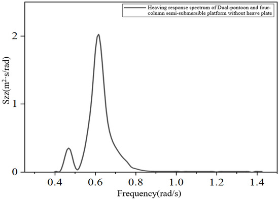
Figure 19.
Heaving response spectrum of dual-pontoon and four-column semi-submersible platform without heave plate.
Next, under the sea state near the Dongsha Islands in the South China Sea, the damping effects of different stiffness values of the PTO system, , are studied according to Equations (1)–(11). If slack mooring is adopted and the coupling effect between the restoring force provided by the mooring system and the motions in other directions is ignored, and if the ratio of the equivalent PTO system stiffness to the hydrostatic restoring stiffness of the platform is defined as , the responses of the platform and the heave plate for different ratios of the equivalent PTO system stiffness, to , are shown in Figure 20. The heaving response of the platform main body is the smallest when the ratio of the equivalent PTO system stiffness to the hydrostatic restoring stiffness of the platform, 0.15, and the response amplitude is approximately 0.84 m. When 0.3 < < 0.6, the integrated system actually increases the extreme value of the platform response. As the stiffness ratio increases, the difference between the heaving displacements of the floating platform and the heave plate decreases and tends to a certain value.
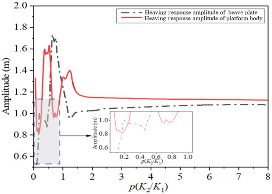
Figure 20.
Relationship between response extremes and stiffness ratio.
Figure 21 shows the variation of the heaving response of the integrated platform with the wave period for stiffness ratios of 0.15 and 0.3, respectively. It can be seen that for high-frequency waves, the heaving response of the platform with a stiffness ratio of = 0.3 is better than that with = 0.15, while the opposite is true for low-frequency waves.
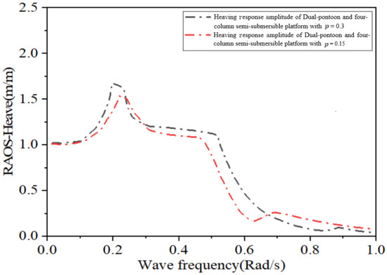
Figure 21.
Heaving RAO versus incoming wave frequency for different PTO stiffnesses.
4. Motion Response of the Integrated Platform Under Different Sea Conditions in the South China Sea
Wave height is generally considered a zero-mean Gaussian stochastic process. The response of the platform to random waves is usually considered the sum of the responses under each component wave. The ANSYS (2024R1) AQWA-DRIFT module (a dedicated hydrodynamic analysis tool for marine structures) calculates the dynamic response under random waves using interpolation.
Taking the ratio of the equivalent PTO system stiffness to the hydrostatic restoring stiffness of the platform, = 0.15, as an example, the sea state with a return period of one year in the Xiwei Trough Sea area of the South China Sea is selected as Sea State 2. The parameters of the working sea state and the long-period sea state of Level 6 are selected as Sea State 1 and Sea State 3, respectively. Then, the heaving performances of the dual-pontoon and four-column semi-submersible platform without a heave plate, the fixed heave plate platform, and the floating platform integrated with the wave energy device are compared under these three sea states. Also, to verify the correctness of the conclusions in the previous section, the stiffness ratio = 0.5, which has a negative effect, is chosen for comparison. The parameters of the three sea conditions are shown in Table 1.

Table 1.
Sea State Conditions.
Neglecting the restoring force provided by the mooring system, the displacement time–history curves within 3000 s for each type of platform under each sea state are solved. The results are summarized based on the heaving displacement curves and probability distributions of each platform in the time domain.
The time–domain heaving curves of each type of heave plate platform under Sea State 1 are shown in Table 2 below. The displacement distributions of the time–domain curves of each platform are statistically analyzed, and the statistics of the mean value, variance, and response extremes of the displacements of each platform are shown in Table 3 below.
Table 2.
Time–domain response curve of each platform under sea state 1.
Table 3.
Extreme values and variances of the response of each platform under sea state 1.
The time–domain analysis and simulation of various types of platforms under Sea State 2 are shown in Table 4 below.
Table 4.
Time–domain response curve of each platform under sea state 2.
The displacement distribution of the time–domain curve of each platform is statistically analyzed, and the mean value, variance, and response extreme value of the displacement of each platform are shown in Table 5 below.
Table 5.
Extreme values and variances of the response of each platform under sea state 2.
The time–domain analysis of various types of platforms under Sea State 3 is carried out for a duration of 3000 s, and the statistics are shown in Table 6 below.
Table 6.
Time–domain response curve of each platform under sea state 3.
The heaving displacement curves and their distributions of each type of platform under Sea State 3 are shown in Table 6. The displacement distribution of the time–domain curve of each platform is statistically analyzed, and the mean value, variance, and extreme value of the displacement of each platform are shown in Table 7 below.
Table 7.
Extreme values and variances of the response of each platform under sea state 3.
The response extreme values and displacement variances of each platform under the three sea states are shown in Figure 22 and Figure 23. Under Sea State 1, the seakeeping performance of each platform is good. The response of the platform without a heave plate is significantly weaker than that of various platforms with heave plates. The vibration damping effect of each platform with a heave plate is obvious. The fixed heave plate reduces the heaving motion by more than 35%, and the heaving motion of the platform structure with a stiffness ratio of = 0.5 for the PTO system and the platform is reduced by more than 50%. In addition, in the sea state with a lower period, the response of the platform with a stiffness ratio of = 0.15 is slightly weaker than that of the platform with a fixed heave plate.
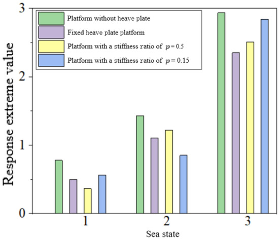
Figure 22.
Extreme values of the heaving response of each platform in three sea states.
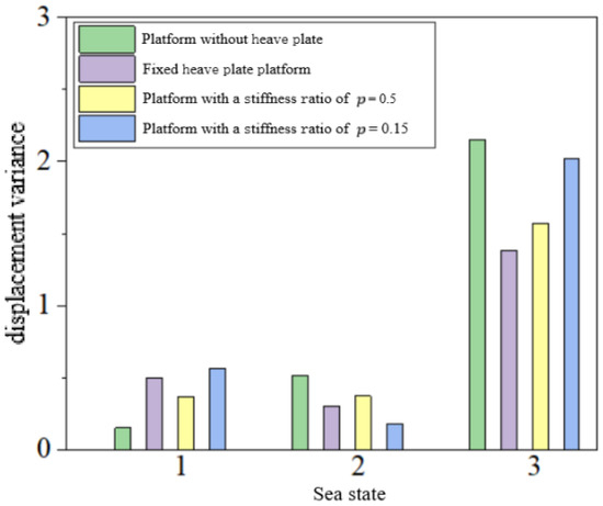
Figure 23.
Displacement variances of each platform in three sea states.
Under Sea State 2, the response of the platform with a stiffness ratio of = 0.15 is better than that of the platform without a heave plate, but the vibration damping effect is slightly reduced compared with Sea State 1. Among them, when = 0.5, the response curve has a wider distribution of positions on the time–domain curve, which is similar to that of the platform without a heave plate, and the expected negative effect is not produced.
In Sea State 3, in terms of the damping ratio, the effect of all types of heave plates is weaker than that in Sea State 2 and Sea State 1. This may be because a large wave period leads to a small acceleration change of the heave plate, which in turn causes a gradual decrease in the ratio of the additional mass to the wave-induced force. The reason for the reduced damping effect of the integrated PTO system may be that it cannot play the role of tuned damping in long periods. In a single upward or downward cycle, the elastic force gradually increases as the relative displacement increases. During this period, it is equivalent to a platform without a heave plate, and it can only be equivalent to the fixed heave plate platform after reaching a certain extreme value.
5. Conclusions
This study proposes an integrated deep-sea platform with wave energy converters based on the principle of tuned damping, deduces the RAO calculation method for the integrated system, and analyzes the damping effect under different PTO stiffnesses. The main conclusions are as follows:
- (1)
- For the three types of semi-submersible platforms, the heave RAO is most significantly improved when the heave plate is installed at 60 m depth within the operational wave period. Beyond 60 m, the improvement effect declines; when the wave period exceeds 25 s, the heave plate negatively affects the platform’s heave response. Among the three platforms, the dual-pontoon and four-column semi-submersible platform achieves the best heave performance improvement after adding a heave plate.
- (2)
- An integrated structural scheme combining the floating pontoon platform with an oscillating float-type wave energy converter is proposed, and the RAO calculation method for this scheme is derived.
- (3)
- In the Xiwei Trough of the South China Sea, when the ratio of PTO stiffness to the platform’s restoring stiffness ( = 0.15), the platform has the smallest response extreme value. When 0.3 < < 0.5, the PTO system negatively impacts the platform’s heaving performance.
- (4)
- Comparative analyses are conducted for the platform without a heave plate, the traditional fixed heave plate platform, the integrated platform with a stiffness ratio of = 0.15, and the integrated platform with a stiffness ratio of = 0.5. Under the Xiwei Trough Sea state, the integrated platform with = 0.15 exhibits better heave performance than the fixed heave plate platform, and the integrated platform with = 0.5 shows a heave response similar to that of the platform without a heave plate. Under the Level VI sea state, the heave response of all platforms increases significantly, the damping effect of the heave plate diminishes notably.
- (5)
- Under more severe sea conditions, the negative impact of the heave plate in the integrated PTO system becomes more pronounced. The wave energy PTO system should be used to switch the wind-wave energy integrated system among three modes—no heave plate, fixed heave plate, and tuned mode—to adapt to different sea conditions.
Author Contributions
G.W., H.Y., F.Z. and Y.S. conceived and designed the study. H.Y., F.Z., Z.Z. and H.J. were responsible for writing the manuscript. R.L., J.L. and Y.Z. processed the data. All authors contributed to the interpretation of the results and agreed to be accountable for all aspects of the work. All authors have read and agreed to the published version of the manuscript.
Funding
This work was supported by the National Natural Science Foundation of China under Grant No. 42472383. The authors would like to thank the financial support from Southwest Petroleum University.
Data Availability Statement
The date that support the findings of this study are available from the corresponding author upon reasonable request.
Conflicts of Interest
Authors Fangyuan Zhou and Zhirui Zhang were employed by the company Daqing Drilling Engineering Co., Ltd., CNPC. Author Yuhang Shen was employed by the company Bohai Drilling Third Drilling Company of China Petroleum Group, CNPC. The remaining authors declare that the research was conducted in the absence of any commercial or financial relationships that could be construed as a potential conflict of interest.
References
- Muliawan, M.J.; Karimirad, M.; Moan, T.; Gao, Z. STC (Spar-Torus Combination): A Combined Spar-Type Floating Wind Turbine and Large Point Absorber Floating Wave Energy Converter—Promising and Challenging. In Proceedings of the ASME 2012 31st International Conference on Ocean, Offshore and Arctic Engineering, Rio de Janeiro, Brazil, 1–6 July 2012. [Google Scholar]
- Muliawan, M.J.; Karimirad, M.; Gao, Z.; Moan, T. Extreme responses of a combined spar-type floating wind turbine and floating wave energy converter (STC) system with survival modes. Ocean. Eng. 2013, 65, 71–82. [Google Scholar] [CrossRef]
- Muliawan, M.J.; Karimirad, M.; Moan, T. Dynamic response and power performance of a combined Spar-type floating wind turbine and coaxial floating wave energy converter. Renew. Energy Int. J. 2013, 50, 47–57. [Google Scholar] [CrossRef]
- Wan, L.; Gao, Z.; Moan, T. Model Test of the STC Concept in Survival Modes. In Proceedings of the ASME 2014 33rd International Conference on Ocean, Offshore and Arctic Engineering, San Francisco, CA, USA, 8–13 June 2014. [Google Scholar]
- Wan, L.; Gao, Z.; Moan, T. Experimental and numerical study of hydrodynamic responses of a combined wind and wave energy converter concept in survival modes. Coast. Eng. 2015, 104, 151–169. [Google Scholar] [CrossRef]
- Ren, N.; Gao, Z.; Moan, T.; Wan, L. Long-term performance estimation of the Spar–Torus-Combination (STC) system with different survival modes. Ocean. Eng. 2015, 108, 716–728. [Google Scholar] [CrossRef]
- Michailides, C.; Gao, Z.; Moan, T. Response analysis of the Combined WindWave Energy Concept SFC in harsh environmental conditions. In Proceedings of the International Conference on Renewable Energies Offshore, Lisbon, Portugal, 24–26 November 2014. [Google Scholar]
- Luan, C.; Michailides, C.; Gao, Z.; Moan, T. Modeling and Analysis of a 5 MW Semi-Submersible Wind Turbine Combined with Three Flap-Type Wave Energy Converters. In Proceedings of the ASME 2014 33rd International Conference on Ocean, Offshore and Arctic Engineering, San Francisco, CA, USA, 8–13 June 2014. [Google Scholar]
- Gao, Z.; Moan, T.; Wan, L.; Michailides, C. Comparative numerical and experimental study of two combined wind and wave energy concepts. J. Ocean. Eng. Sci. 2016, 1, 36–51. [Google Scholar] [CrossRef]
- Michailides, C.; Gao, Z.; Moan, T. Experimental study of the functionality of a semisubmersible wind turbine combined with flap-type Wave Energy Converters. Renew. Energy Int. J. 2016, 93, 675–690. [Google Scholar] [CrossRef]
- Ren, N.; Ma, Z.; Fan, T.; Zhai, G.; Ou, J. Experimental and numerical study of hydrodynamic responses of a new combined monopile wind turbine and a heave-type wave energy converter under typical operational conditions. Ocean. Eng. 2018, 159, 1–8. [Google Scholar] [CrossRef]
- Ren, N.; Ma, Z.; Shan, B.; Ning, D.; Ou, J. Experimental and numerical study of dynamic responses of a new combined TLP type floating wind turbine and a wave energy converter under operational conditions. Renew. Energy 2020, 151, 966–974. [Google Scholar] [CrossRef]
- Hu, J.; Zhou, B.; Vogel, C.; Liu, P.; Willden, R.; Sun, K.; Zang, J.; Geng, J.; Jin, P.; Cui, L.; et al. Optimal design and performance analysis of a hybrid system combing a floating wind platform and wave energy converters. Appl. Energy 2020, 269, 114998. [Google Scholar] [CrossRef]
- Wang, Y.P. Research on Integrated Wind-Wave Energy System Based on Semi-Submersible Platform. Master’s Thesis, Dalian University of Technology, Dalian, China, 2021. (In Chinese). [Google Scholar]
- Wang, Y. Study on Hydrodynamic Characteristics of Semi-Submersible Platform and Heaving Wave Energy Converter System. Master’s Thesis, Harbin Engineering University, Harbin, China, 2021. (In Chinese). [Google Scholar]
- Ghafari, H.R.; Ghassemi, H.; He, G. Numerical study of the Wavestar wave energy converter with multi-point-absorber around DeepCwind semisubmersible floating platform. Ocean. Eng. 2021, 232, 109177. [Google Scholar] [CrossRef]
- Ghafari, H.R.; Ghassemi, H.; Abbasi, A.; Vakilabadi, K.A.; Yazdi, H.; He, G. Novel concept of hybrid wavestar- floating offshore wind turbine system with rectilinear arrays of WECs. Ocean. Eng. 2022, 262, 112253. [Google Scholar] [CrossRef]
- Ghafari, H.R.; Ghassemi, H.; Neisi, A. Power matrix and dynamic response of the hybrid Wavestar-DeepCwind platform under different diameters and regular wave conditions. Ocean. Eng. 2022, 247, 110734. [Google Scholar] [CrossRef]
- Homayoun, E.; Panahi, S.; Ghassemi, H.; He, G.; Liu, P. Power absorption of combined wind turbine and wave energy converter mounted on braceless floating platform. Ocean. Eng. 2022, 266, 113027. [Google Scholar] [CrossRef]
- Zhou, B.; Wang, Y.; Zheng, Z.; Jin, P.; Ning, D. Power generation and wave attenuation of a hybrid system involving a heaving cylindrical wave energy converter in front of a parabolic breakwater. Energy 2023, 282, 128364. [Google Scholar] [CrossRef]
- Zhou, B.; Hu, J.; Wang, Y.; Jin, P.; Jing, F.; Ning, D. Coupled dynamic and power generation characteristics of a hybrid system consisting of a semi-submersible wind turbine and an array of heaving wave energy converters. Renew. Energy 2023, 214, 23–38. [Google Scholar] [CrossRef]
- Halkyard, J.; Chao, J.; Abbott, P.; Dagleish, J.; Banon, H.; Thiagarajan, K. A Deep Draft Semisubmersible with a Retractable Heave Plate. In Proceedings of the Offshore Technology Conference, Houston, TX, USA, 6–9 May 2002. [Google Scholar]
- Du, Y.; Wang, K.; Li, F.P. Study on added mass of heave plates for semi-submersible floating wind turbines. Ship Eng. 2023, 45, 167–172. (In Chinese) [Google Scholar]
- Yue, M.; Liu, Q.; Li, C.; Ding, Q.; Cheng, S.; Zhu, H. Effects of heave plate on dynamic response of floating wind turbine Spar platform under the coupling effect of wind and wave. Ocean. Eng. 2020, 201, 107103. [Google Scholar] [CrossRef]
- Zhang, L.; Shi, W.; Zeng, Y.; Michailides, C.; Zheng, S.; Li, Y. Experimental investigation on the hydrodynamic effects of heave plates used in floating offshore wind turbines. Ocean. Eng. 2023, 267, 113103. [Google Scholar] [CrossRef]
- Chen, B.; Yu, Z.; Lyu, Y.; Li, X.; Li, C. A new type of anti-heave semi-submersible drilling platform. Pet. Explor. Dev. 2017, 44, 487–494. [Google Scholar] [CrossRef]
- Lopez-Pavon, C.; Souto-Iglesias, A. Hydrodynamic coefficients and pressure loads on heave plates for semi-submersible floating offshore wind turbines: A comparative analysis using large scale models. Renew. Energy Int. J. 2015, 81, 864–881. [Google Scholar] [CrossRef]
- Jiang, Y.; Hu, G.; Zong, Z.; Zou, L.; Jin, G. Influence of an Integral Heave Plate on the Dynamic Response of Floating Offshore Wind Turbine Under Operational and Storm Conditions. Energies 2020, 13, 6122. [Google Scholar] [CrossRef]
- Chen, C.Y.; Mei, X.; Mills, T. Effect of Heave Plate on Semisubmersible Response. In Proceedings of the 17th International Offshore and Polar Engineering Conference (ISOPE-2007), Lisbon, Portugal, 1–6 July 2007. [Google Scholar]
- Frahm, H. Device for Damping Vibrations of Bodies. U.S. Patent 989958A, 18 April 1911. [Google Scholar]
- Zhu, S.; Shen, W.A.; Xu, Y.L. Linear electromagnetic devices for vibration damping and energy harvesting: Modeling and testing. Eng. Struct. 2012, 34, 198–212. [Google Scholar] [CrossRef]
- Ali, S.F.; Adhikari, S. Energy Harvesting Dynamic Vibration Absorbers. J. Appl. Mech.-Trans. ASME 2013, 80, 041004. [Google Scholar] [CrossRef]
- Gonzalez-Buelga, A.; Clare, L.R.; Cammarano, A.; Neild, S.A.; Burrow, S.G.; Inman, D.J. An optimised tuned mass damper/harvester device. Struct. Control Health Monit. 2014, 21, 1154–1169. [Google Scholar] [CrossRef]
- Zhao, F.; Wang, Z.; Bai, H.; Tang, H. Energy harvesting based on flow-induced vibration of a wavy cylinder coupled with tuned mass damper. Energy 2023, 282, 128584. [Google Scholar] [CrossRef]
- Long, Z.; Shen, W.; Zhu, H. On energy dissipation or harvesting of tuned viscous mass dampers for SDOF structures under seismic excitations. Mech. Syst. Signal Process. 2023, 189, 110087. [Google Scholar] [CrossRef]
- Nerubenko, G.; Blintsov, V.; Mozgovyy, A.; Biliuk, I. The Novel Wave Energy Harvesting Buoy. In Proceedings of the 2019 International Conference on Power Generation Systems and Renewable Energy Technologies (PGSRET), Istanbul, Turkey, 26–27 August 2019. [Google Scholar]


Disclaimer/Publisher’s Note: The statements, opinions and data contained in all publications are solely those of the individual author(s) and contributor(s) and not of MDPI and/or the editor(s). MDPI and/or the editor(s) disclaim responsibility for any injury to people or property resulting from any ideas, methods, instructions or products referred to in the content. |
© 2025 by the authors. Licensee MDPI, Basel, Switzerland. This article is an open access article distributed under the terms and conditions of the Creative Commons Attribution (CC BY) license (https://creativecommons.org/licenses/by/4.0/).