Figure 1.
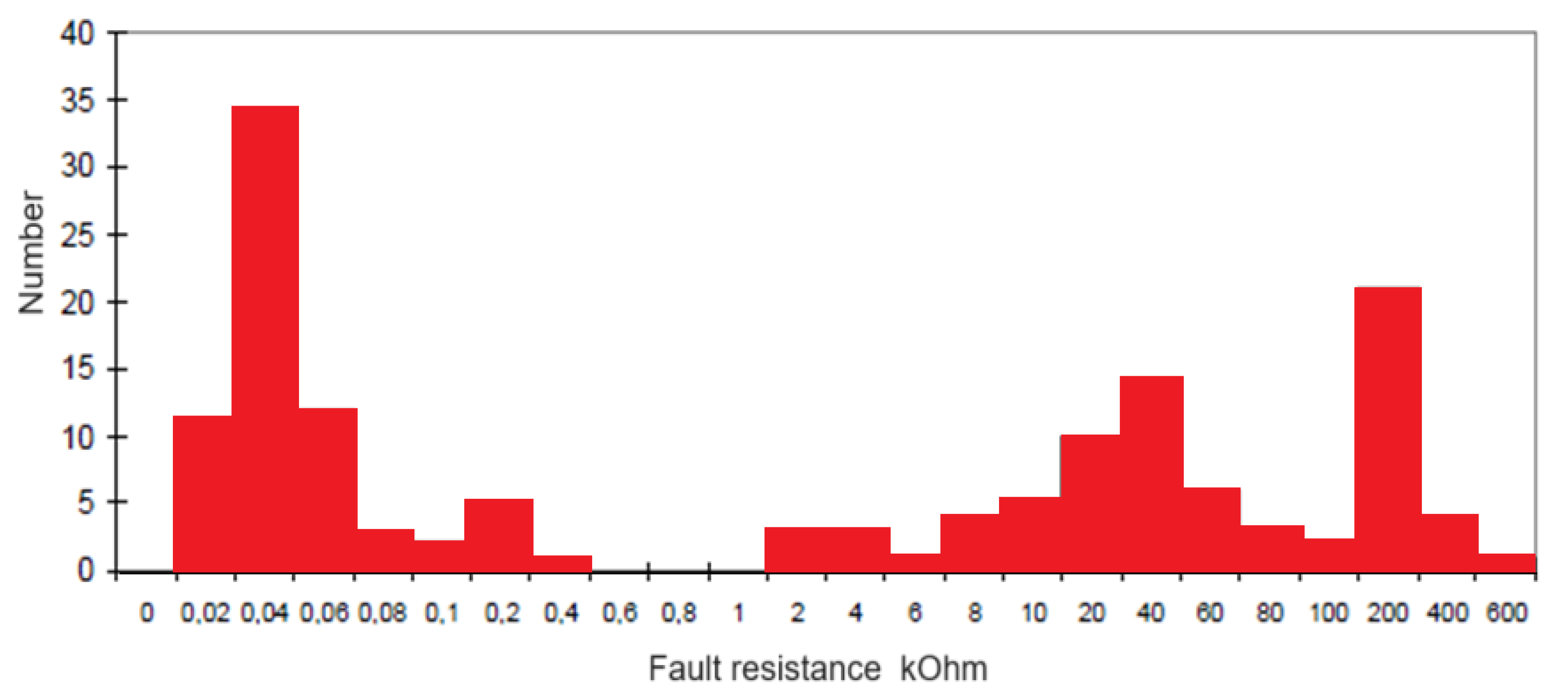
Distribution of the number of SPGFs versus transient resistance values at the fault location in a 10 kV network [
23].
Figure 1.
Distribution of the number of SPGFs versus transient resistance values at the fault location in a 10 kV network [
23].
Figure 2.
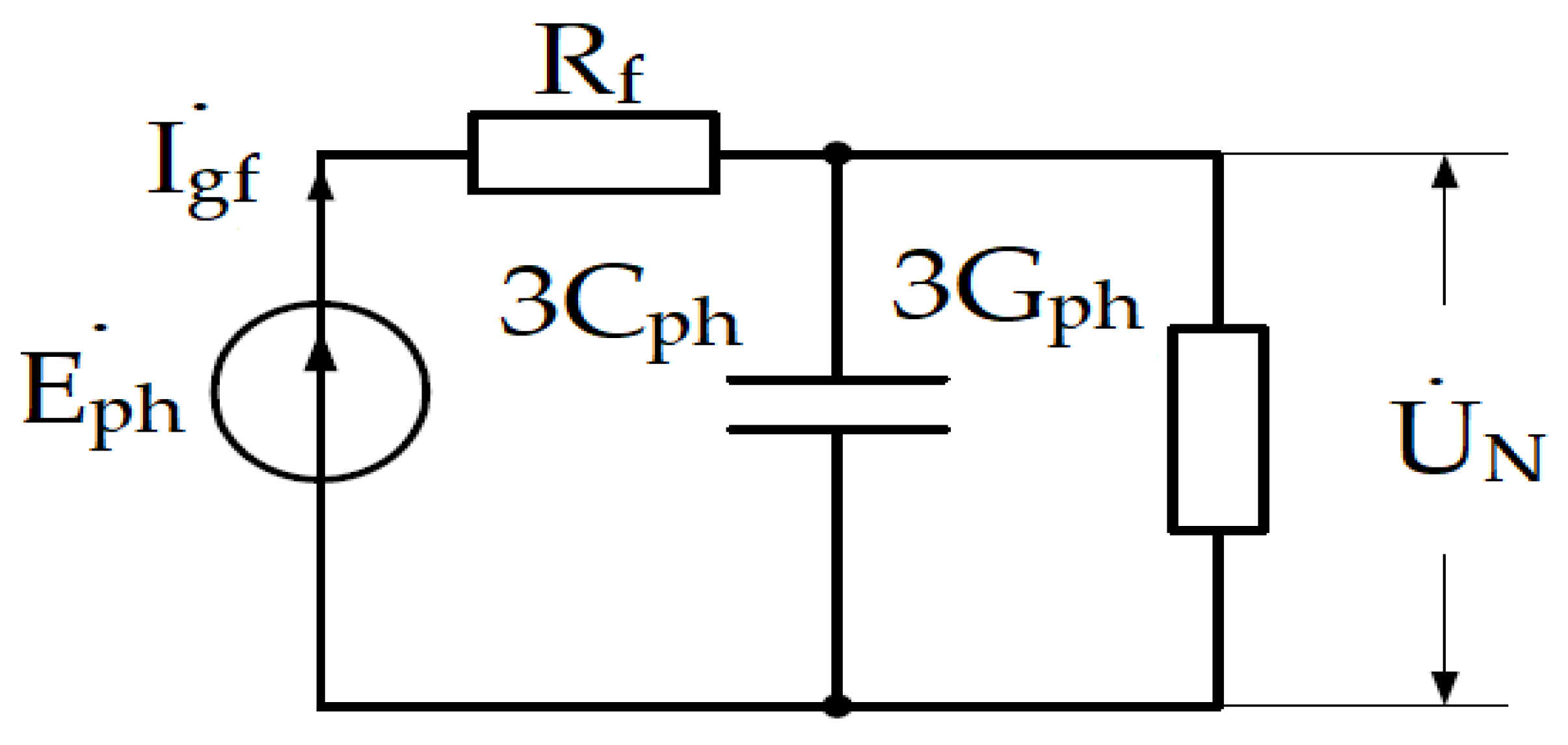
Equivalent zero-sequence diagram for a single-phase-to-ground fault.
Figure 2.
Equivalent zero-sequence diagram for a single-phase-to-ground fault.
Figure 3.
Graph of the dependence of the ground fault current on the transient resistance.
Figure 3.
Graph of the dependence of the ground fault current on the transient resistance.
Figure 4.
Error in UN (%) against admittance imbalance and transient resistance at 10 kV with the time step of 0.001 s.
Figure 4.
Error in UN (%) against admittance imbalance and transient resistance at 10 kV with the time step of 0.001 s.
Figure 5.
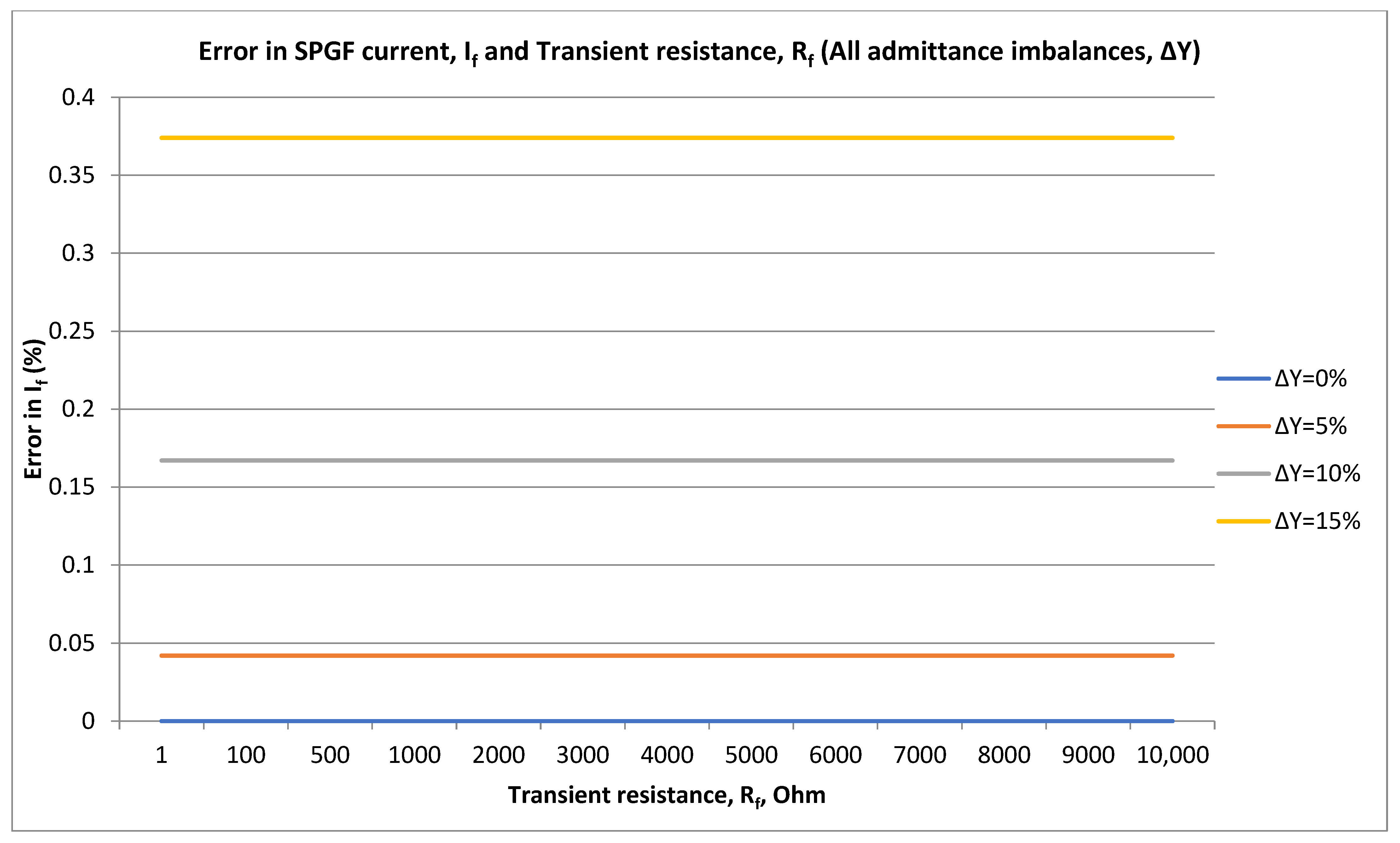
Error in If (%) against admittance imbalance at 10 kV with the time step of 0.001 s.
Figure 5.
Error in If (%) against admittance imbalance at 10 kV with the time step of 0.001 s.
Figure 6.
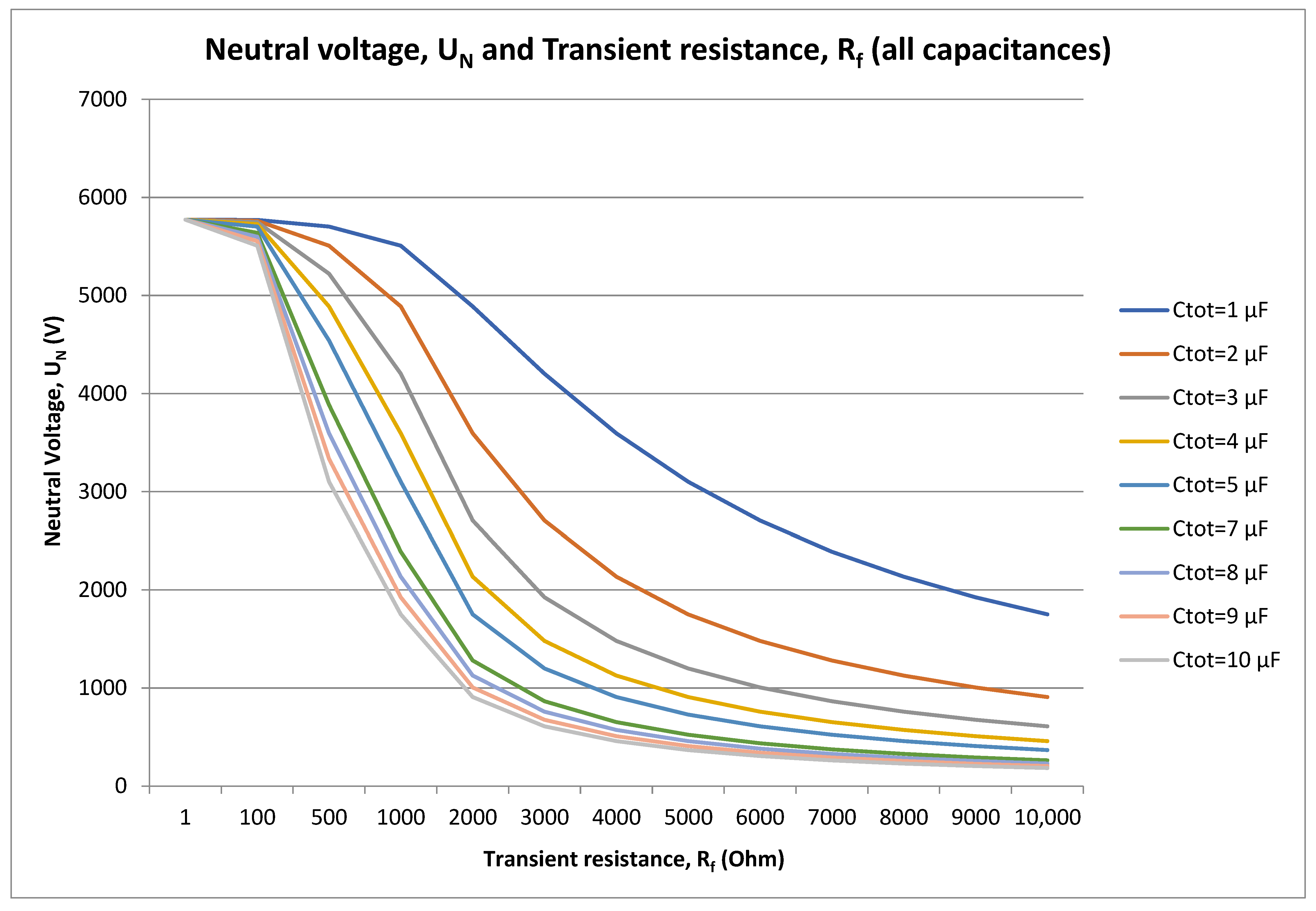
Dependence of capacitance and neutral voltage from transient resistance at 10 kV with the time step of 0.001 s.
Figure 6.
Dependence of capacitance and neutral voltage from transient resistance at 10 kV with the time step of 0.001 s.
Figure 7.
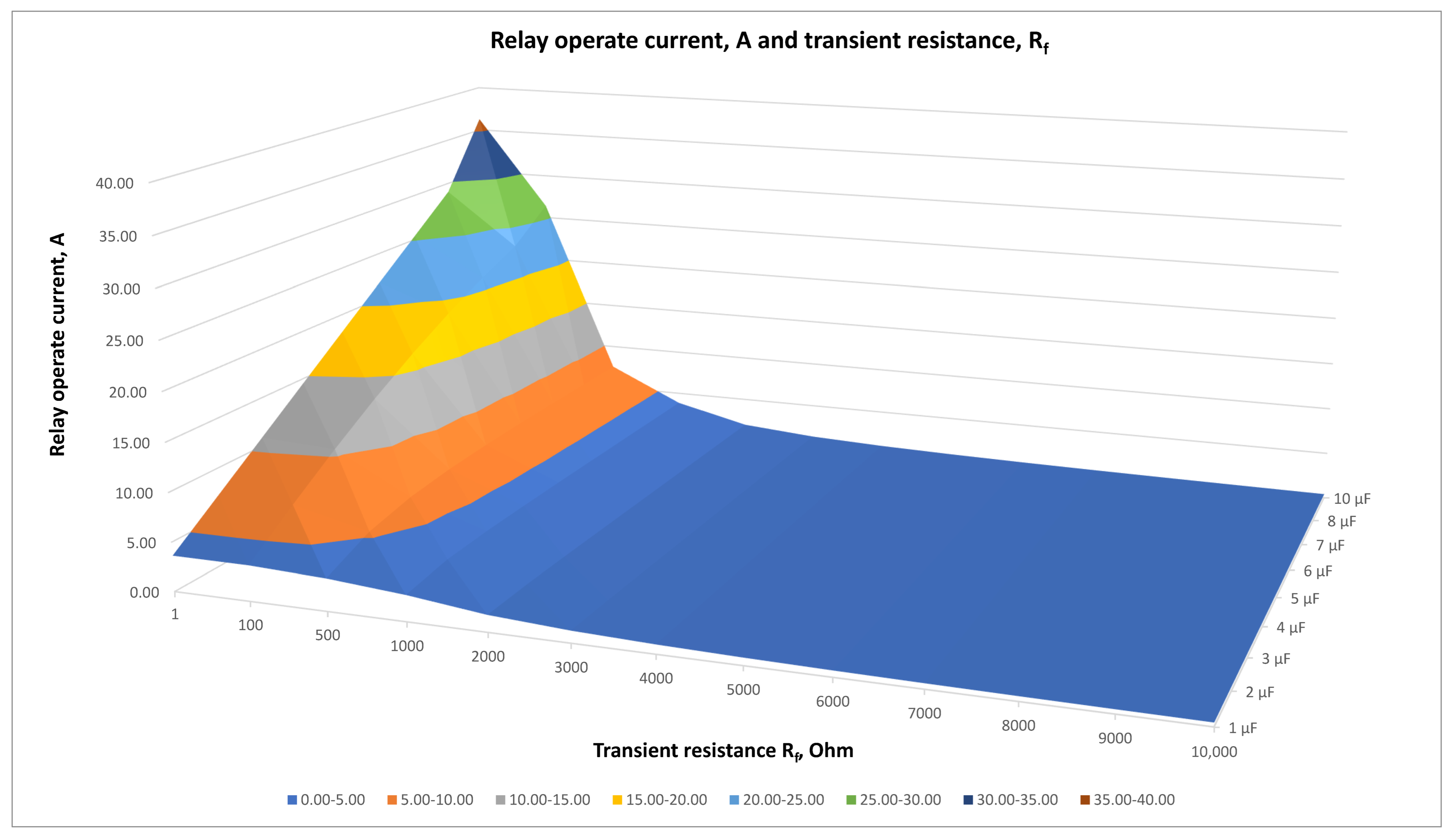
SPGF current, If, A and transient resistance, Rf at 10 kV with the time step of 0.001 s.
Figure 7.
SPGF current, If, A and transient resistance, Rf at 10 kV with the time step of 0.001 s.
Figure 8.
Ground overcurrent settings for various transient resistances at 10 kV with the time step of 0.001 s.
Figure 8.
Ground overcurrent settings for various transient resistances at 10 kV with the time step of 0.001 s.
Figure 9.
Loop integrity coefficient, β and transient resistance, Rf at 10 kV with the time step of 0.001 s.
Figure 9.
Loop integrity coefficient, β and transient resistance, Rf at 10 kV with the time step of 0.001 s.
Figure 10.
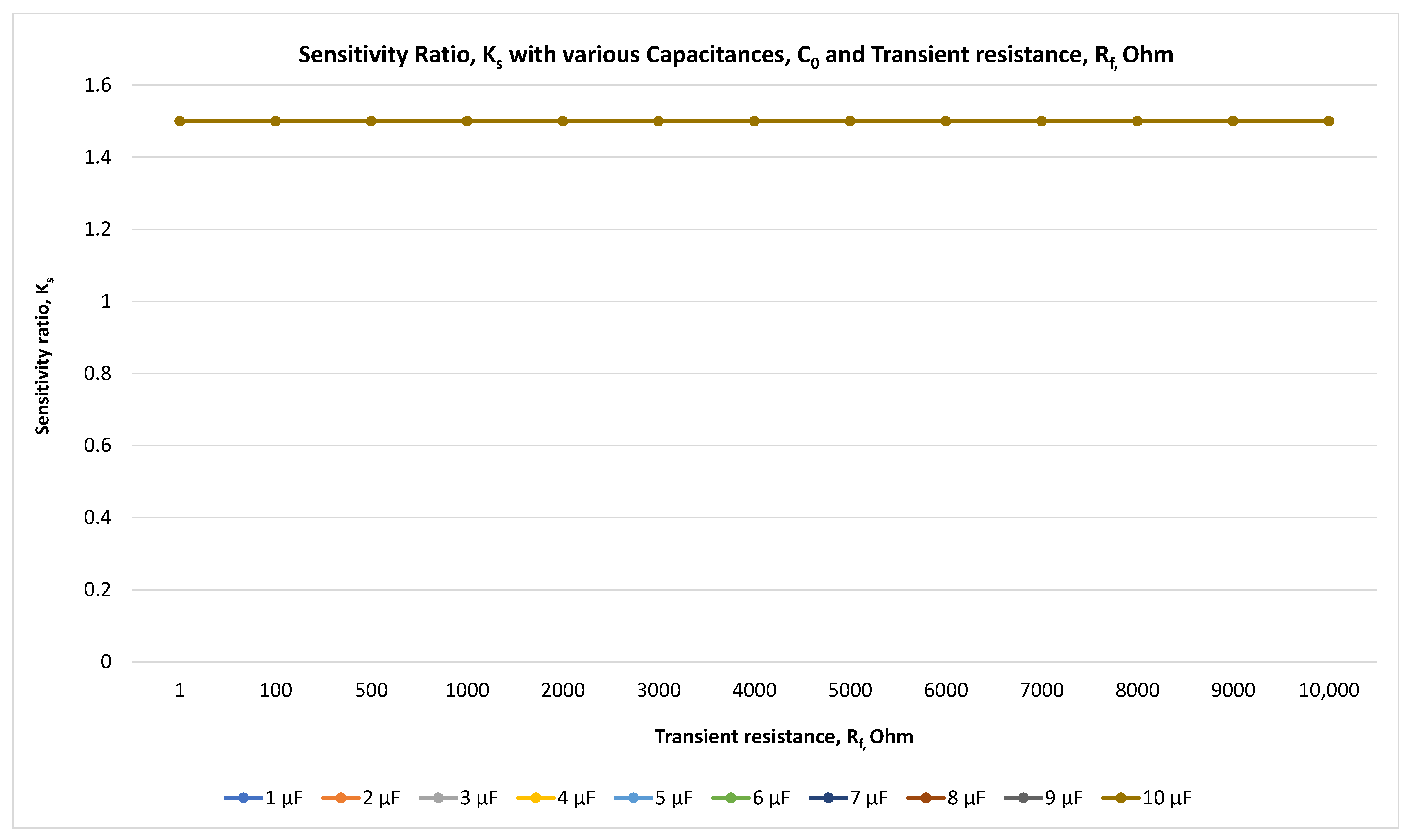
Sensitivity factor evaluation at 10 kV with the time step of 0.001 s.
Figure 10.
Sensitivity factor evaluation at 10 kV with the time step of 0.001 s.
Figure 11.
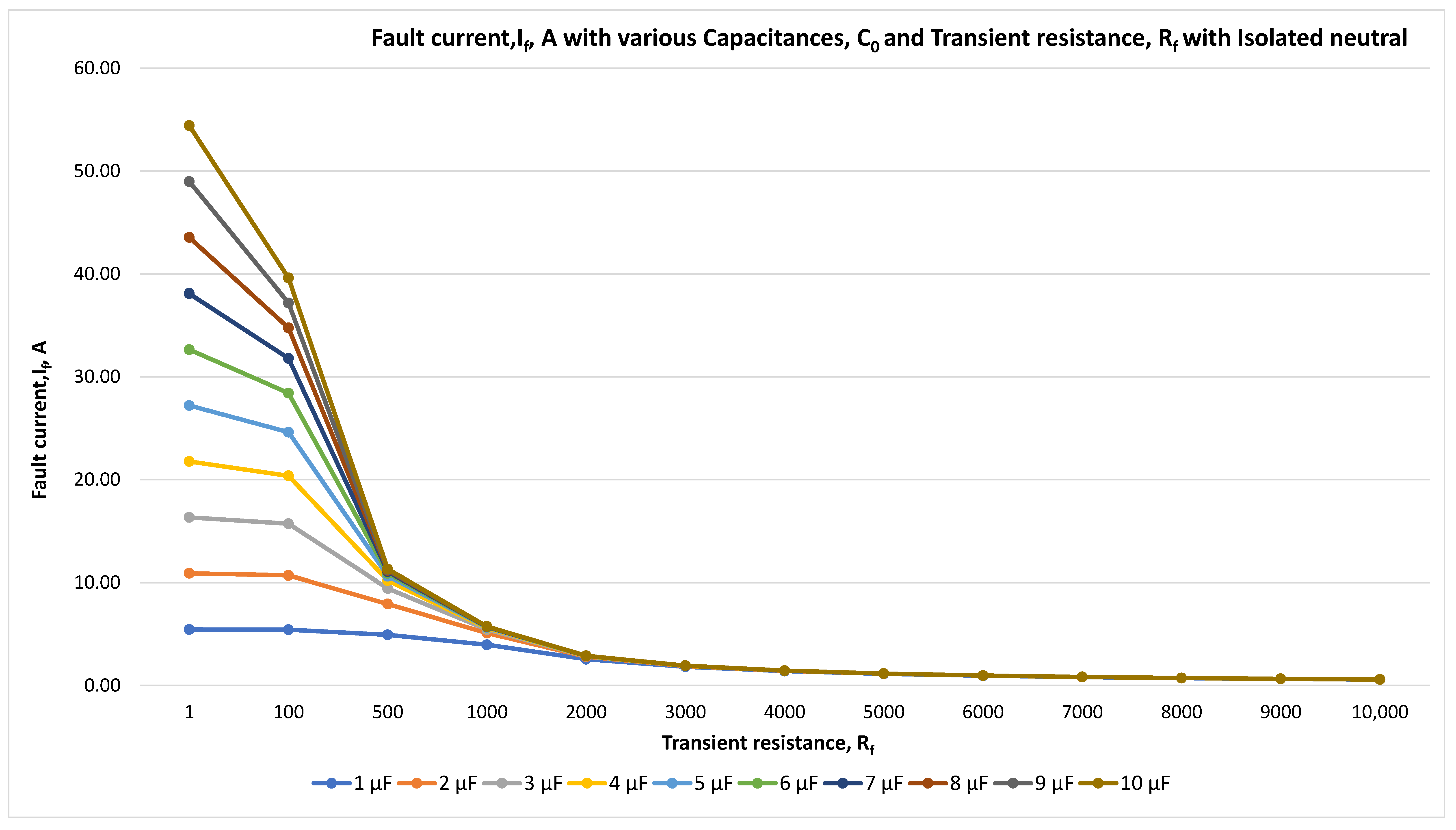
Fault current, If, A, and transient resistance, Rf for isolated neutral at 10 kV with the time step of 0.001 s.
Figure 11.
Fault current, If, A, and transient resistance, Rf for isolated neutral at 10 kV with the time step of 0.001 s.
Figure 12.
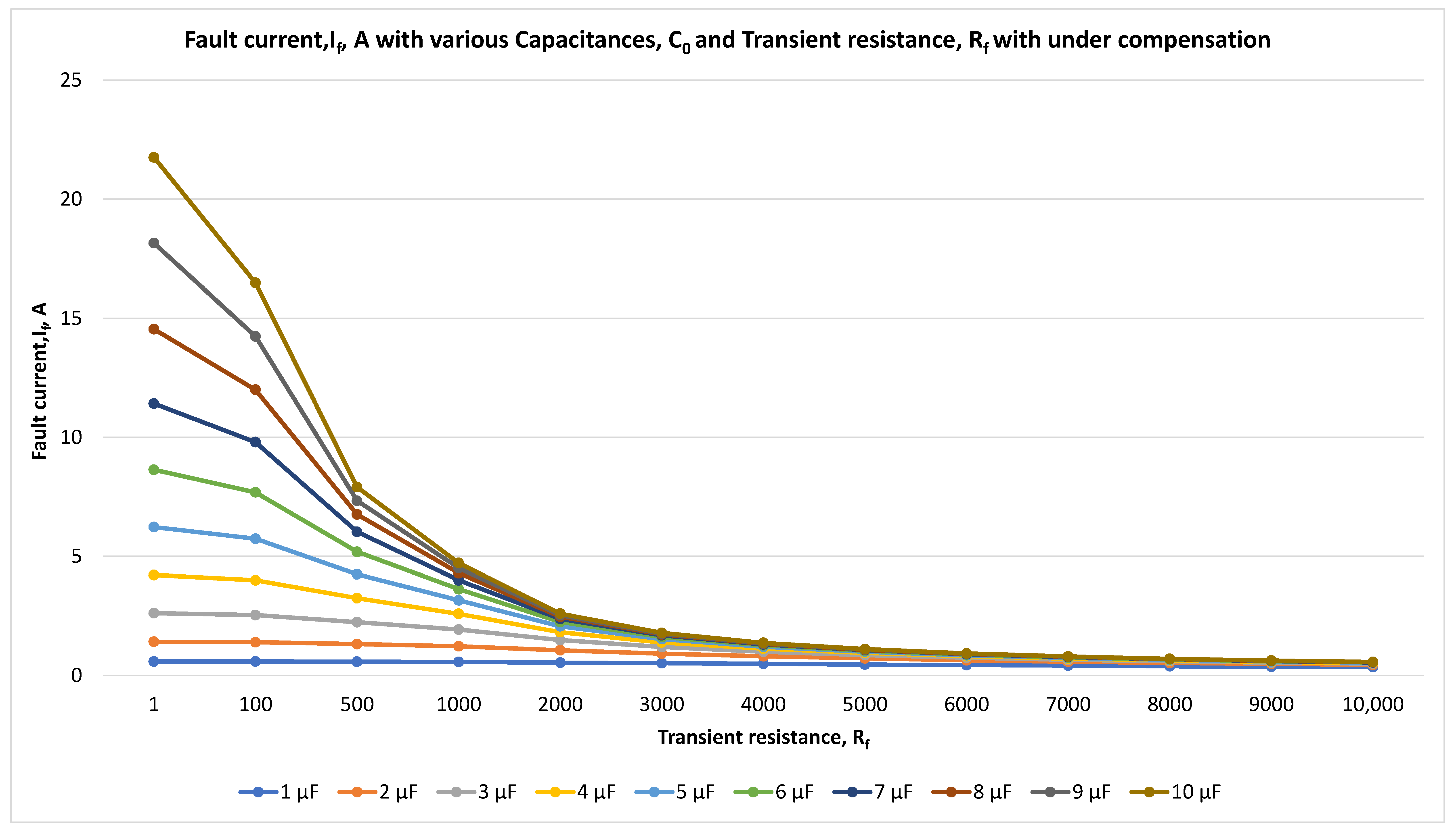
Fault current, If, A, and transient resistance, Rf for compensated neutral with under compensation at 10 kV with the time step of 0.001 s.
Figure 12.
Fault current, If, A, and transient resistance, Rf for compensated neutral with under compensation at 10 kV with the time step of 0.001 s.
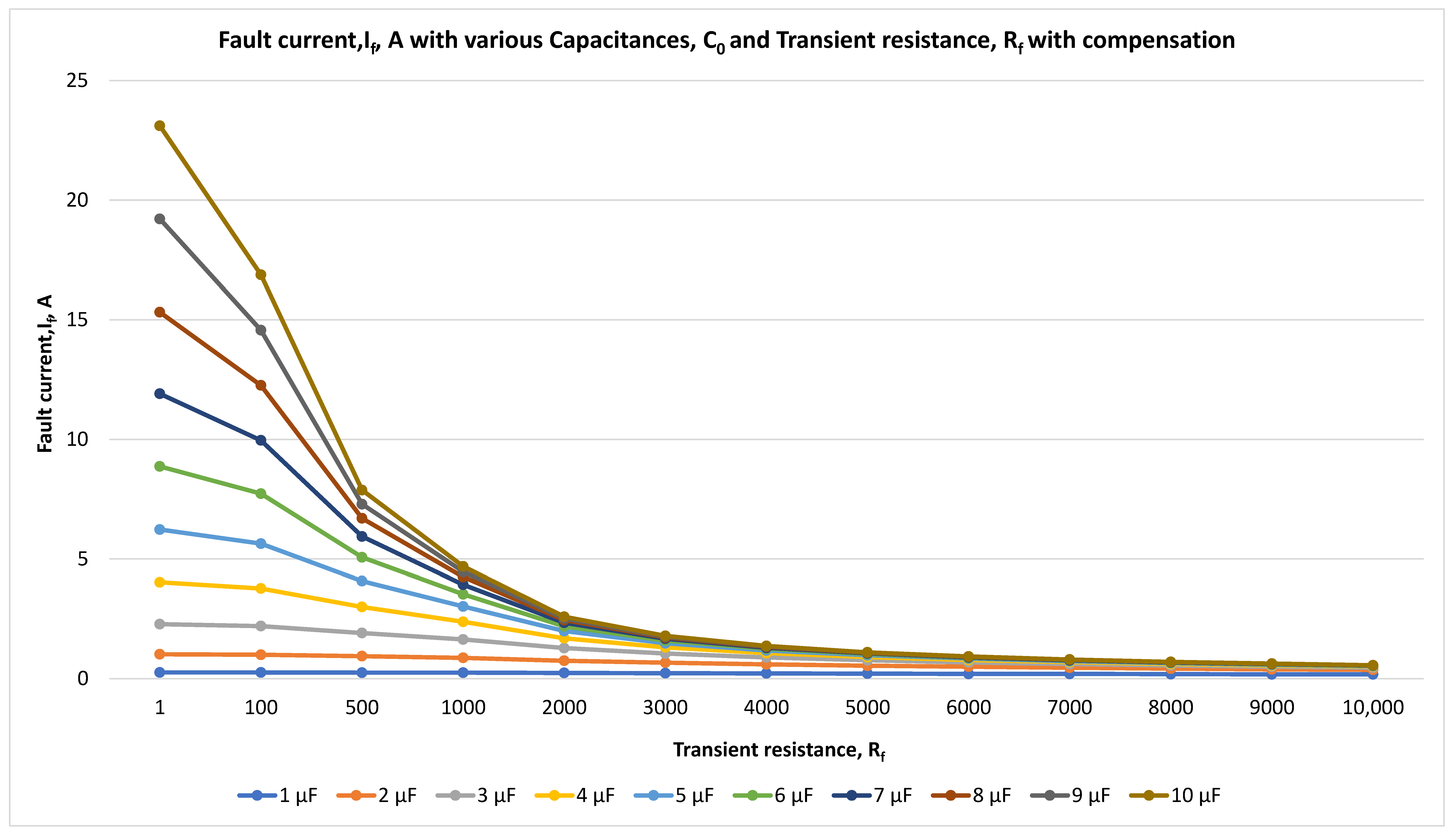
Figure 13.
Fault current, If, A, and transient resistance, Rf for compensated neutral with compensation at 10 kV with the time step of 0.001 s.
Figure 13.
Fault current, If, A, and transient resistance, Rf for compensated neutral with compensation at 10 kV with the time step of 0.001 s.
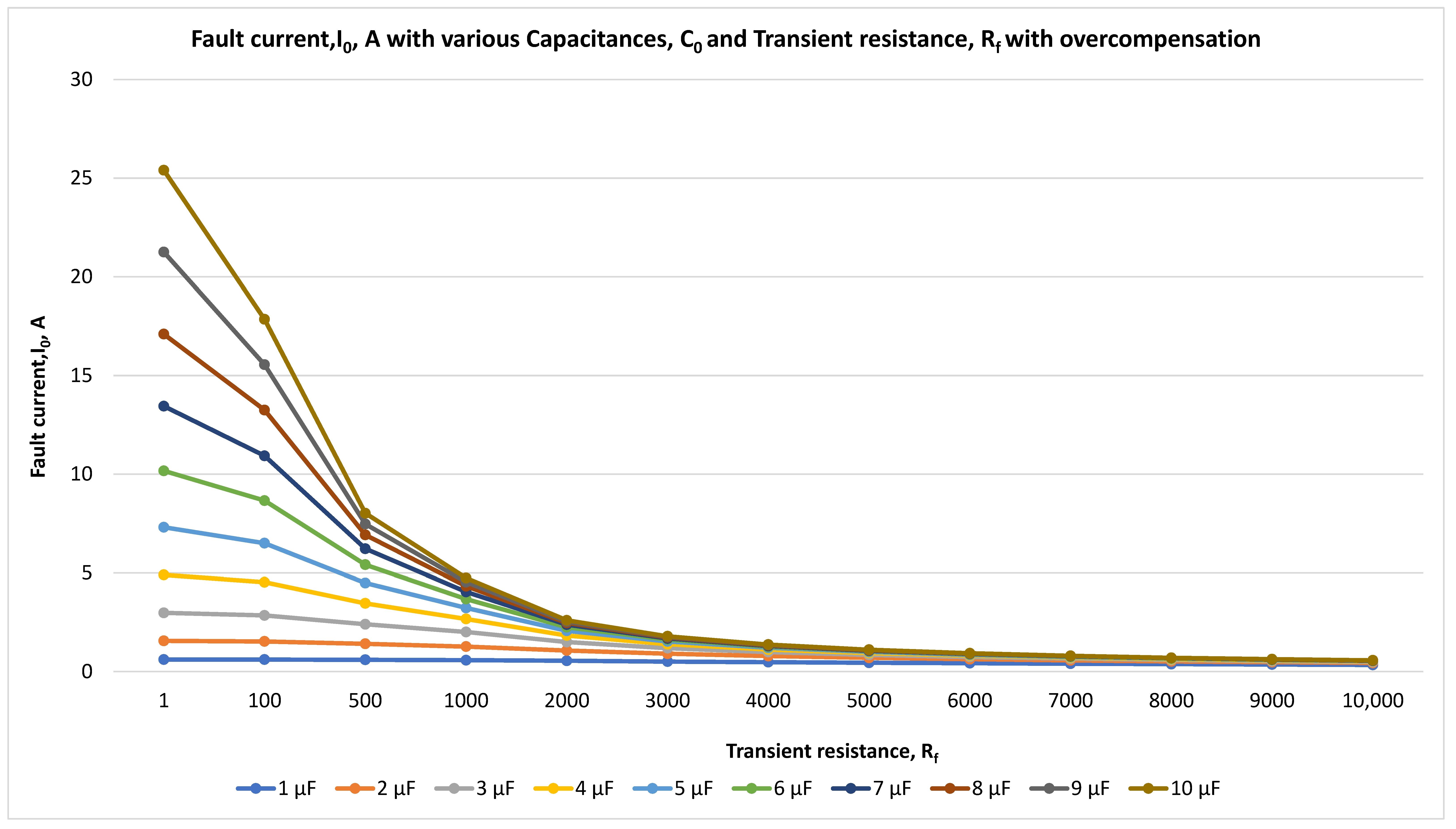
Figure 14.
Fault current, If, A, and transient resistance, Rf for compensated neutral with overcompensation at 10 kV with the time step of 0.001 s.
Figure 14.
Fault current, If, A, and transient resistance, Rf for compensated neutral with overcompensation at 10 kV with the time step of 0.001 s.
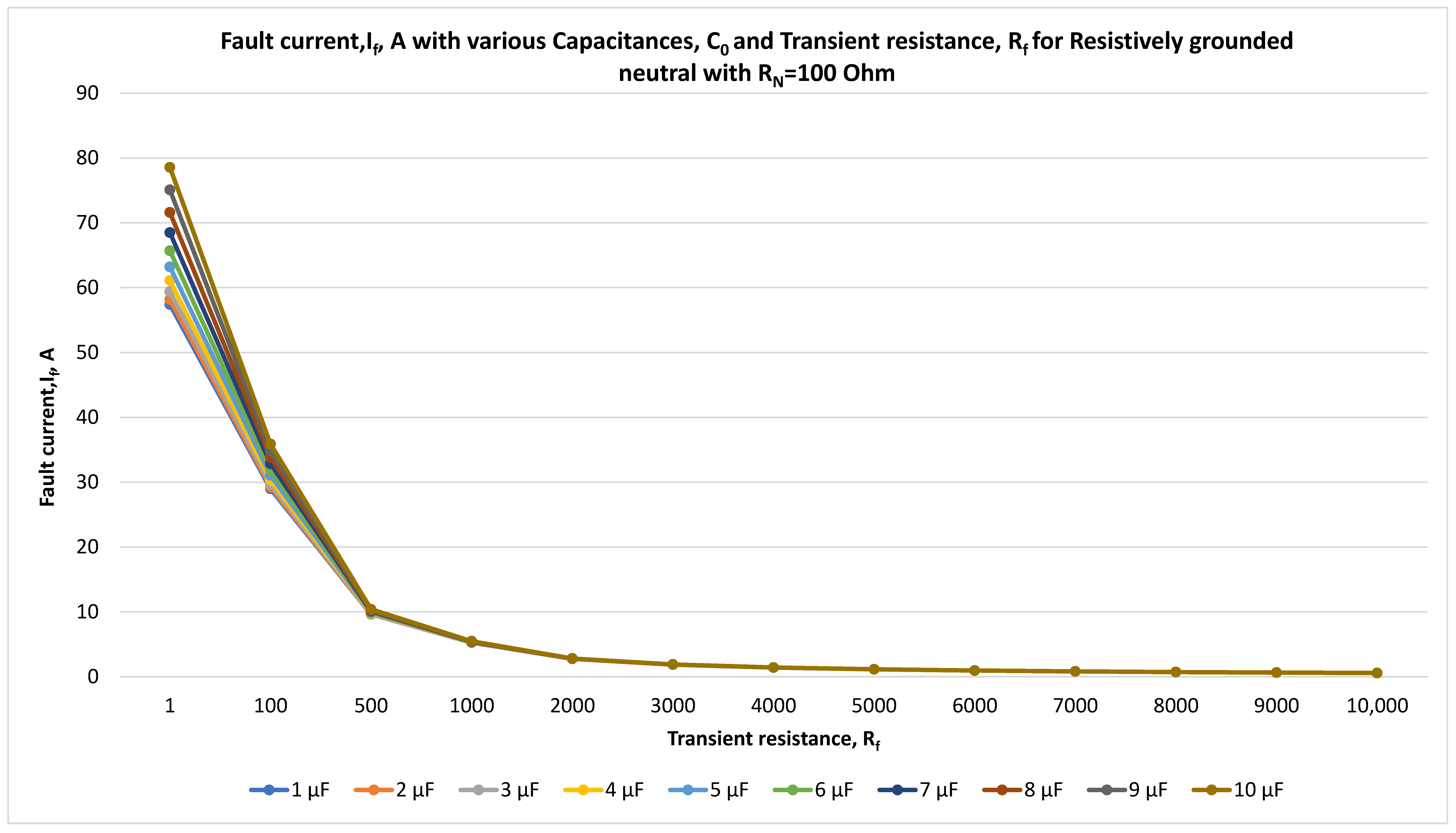
Figure 15.
Fault current, If, A, and transient resistance, Rf for resistively grounded neutral with RN = 100 Ohm at 10 kV with the time step of 0.001 s.
Figure 15.
Fault current, If, A, and transient resistance, Rf for resistively grounded neutral with RN = 100 Ohm at 10 kV with the time step of 0.001 s.
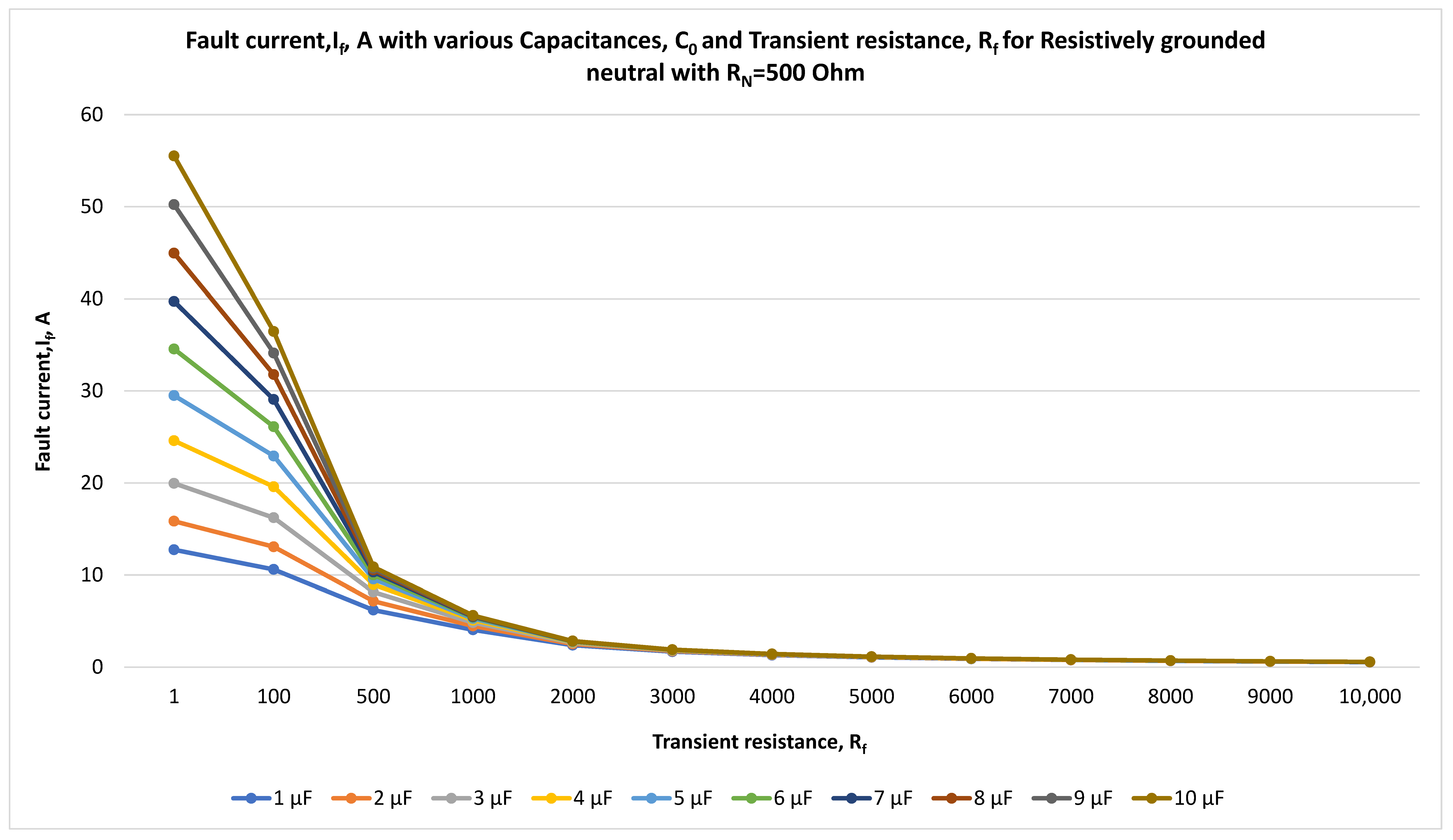
Figure 16.
Fault current, If, A, and transient resistance, Rf for resistively grounded neutral with RN = 500 Ohm at 10 kV with the time step of 0.001 s.
Figure 16.
Fault current, If, A, and transient resistance, Rf for resistively grounded neutral with RN = 500 Ohm at 10 kV with the time step of 0.001 s.
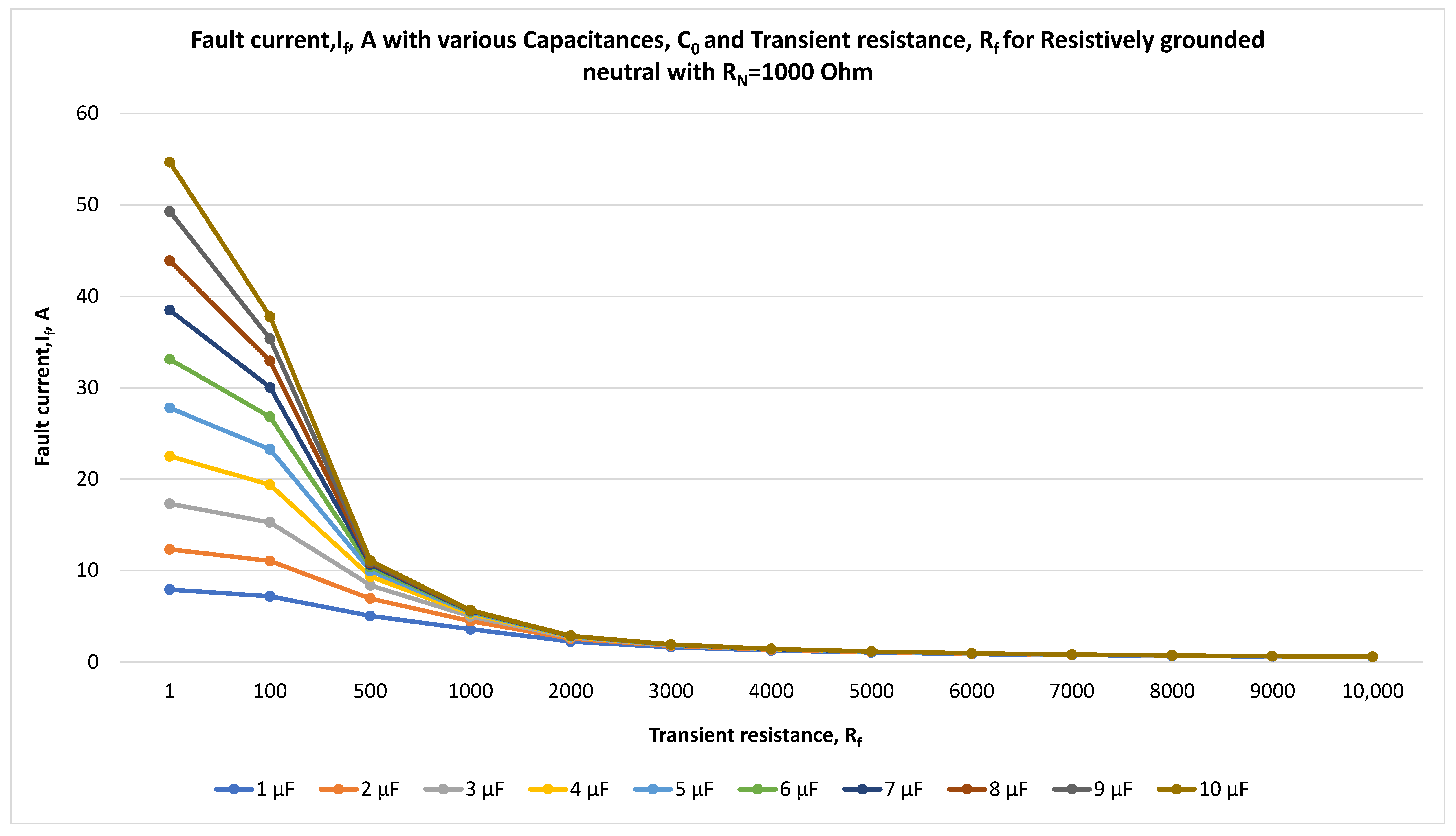
Figure 17.
Fault current, If, A, and transient resistance, Rf for resistively grounded neutral with RN = 1000 Ohm at 10 kV with the time step of 0.001 s.
Figure 17.
Fault current, If, A, and transient resistance, Rf for resistively grounded neutral with RN = 1000 Ohm at 10 kV with the time step of 0.001 s.
Figure 18.
CGFPU operation during SPGF for compensated network at 10 kV with the time step of 0.001 s.
Figure 18.
CGFPU operation during SPGF for compensated network at 10 kV with the time step of 0.001 s.
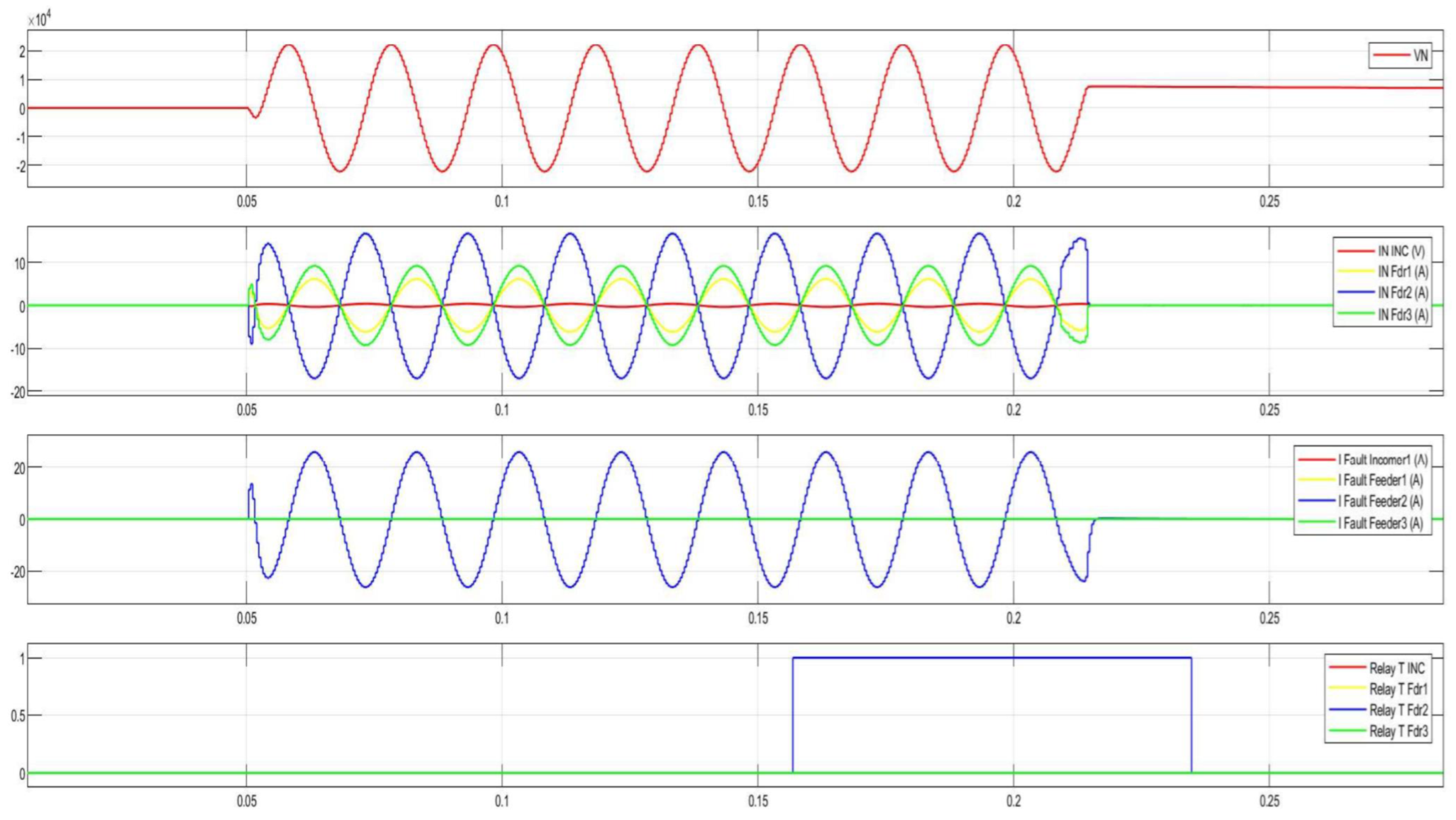
Figure 19.
CGFPU operation during SPGF for resistively grounded network at 10 kV with the time step of 0.001 s.
Figure 19.
CGFPU operation during SPGF for resistively grounded network at 10 kV with the time step of 0.001 s.
Figure 20.
Functional diagram of the CGFPU in the 10 kV network with the isolated neutral configuration.
Figure 20.
Functional diagram of the CGFPU in the 10 kV network with the isolated neutral configuration.
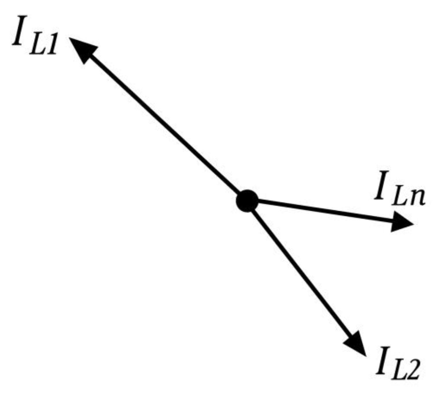
Figure 21.
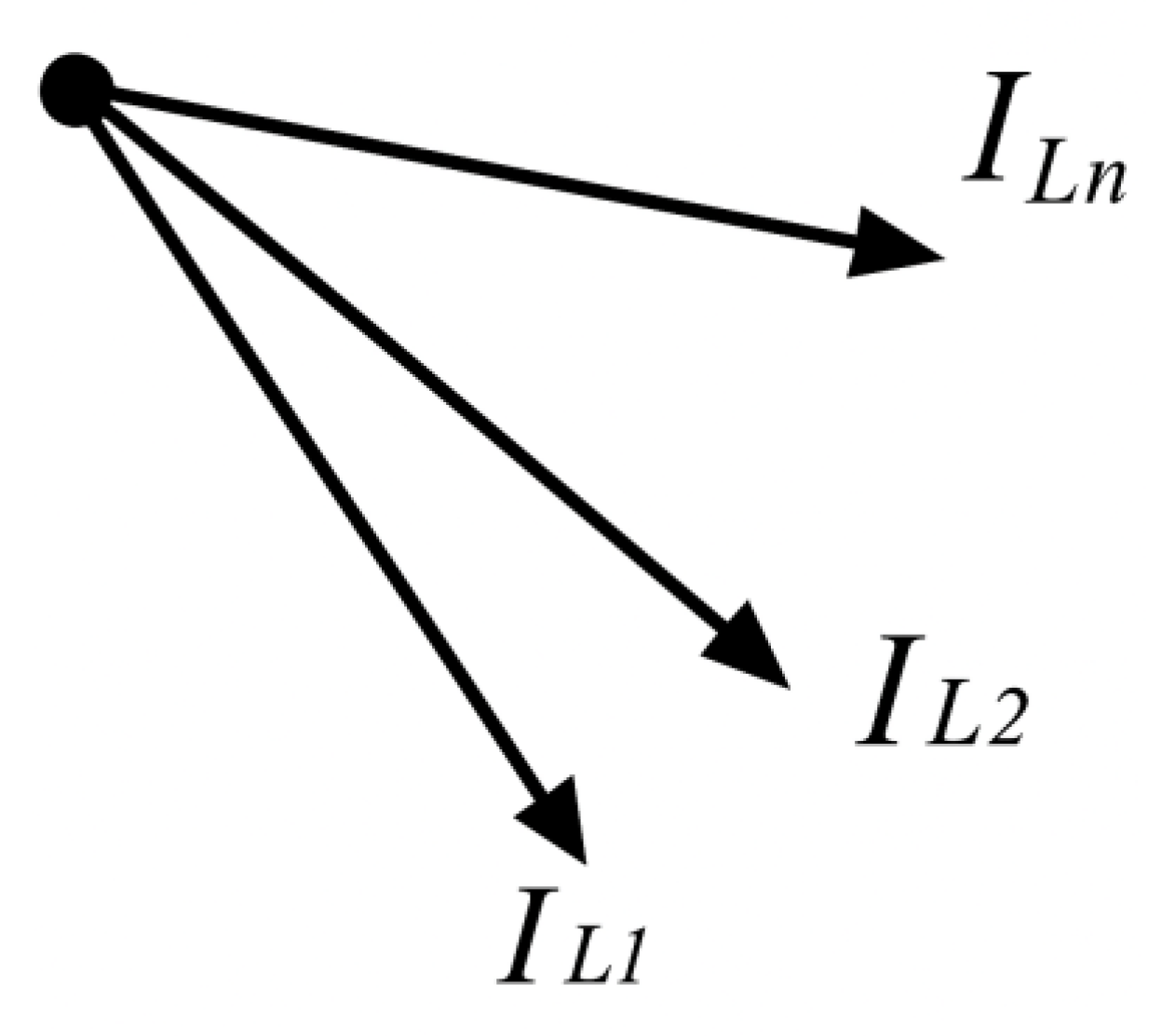
Phasor diagram of the ground fault current and capacitive currents during a ground fault on an outgoing feeder.
Figure 21.
Phasor diagram of the ground fault current and capacitive currents during a ground fault on an outgoing feeder.
Figure 22.
Phasor diagram of zero-sequence currents during ground fault on the 10 kV busbars.
Figure 22.
Phasor diagram of zero-sequence currents during ground fault on the 10 kV busbars.
Figure 23.
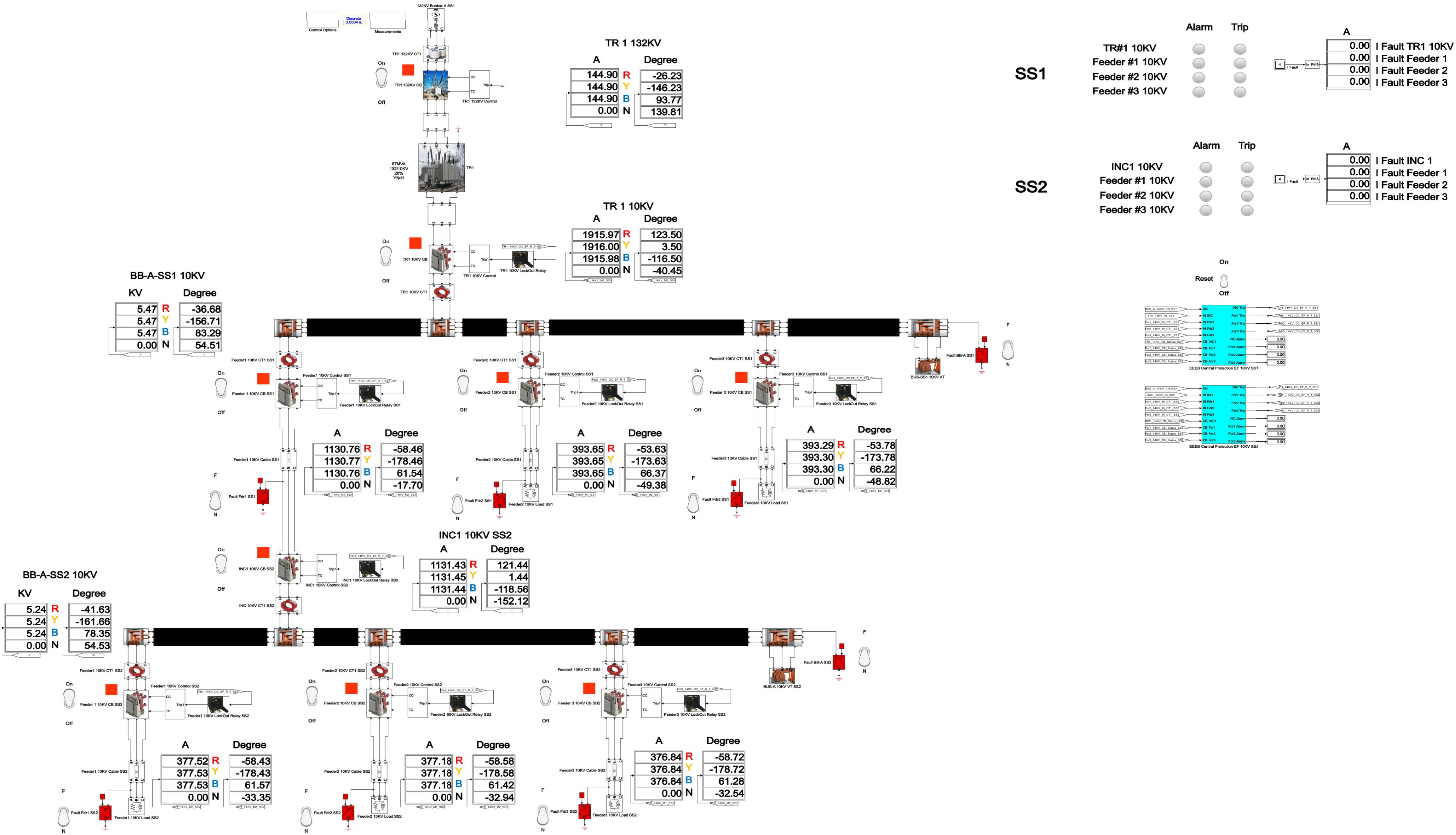
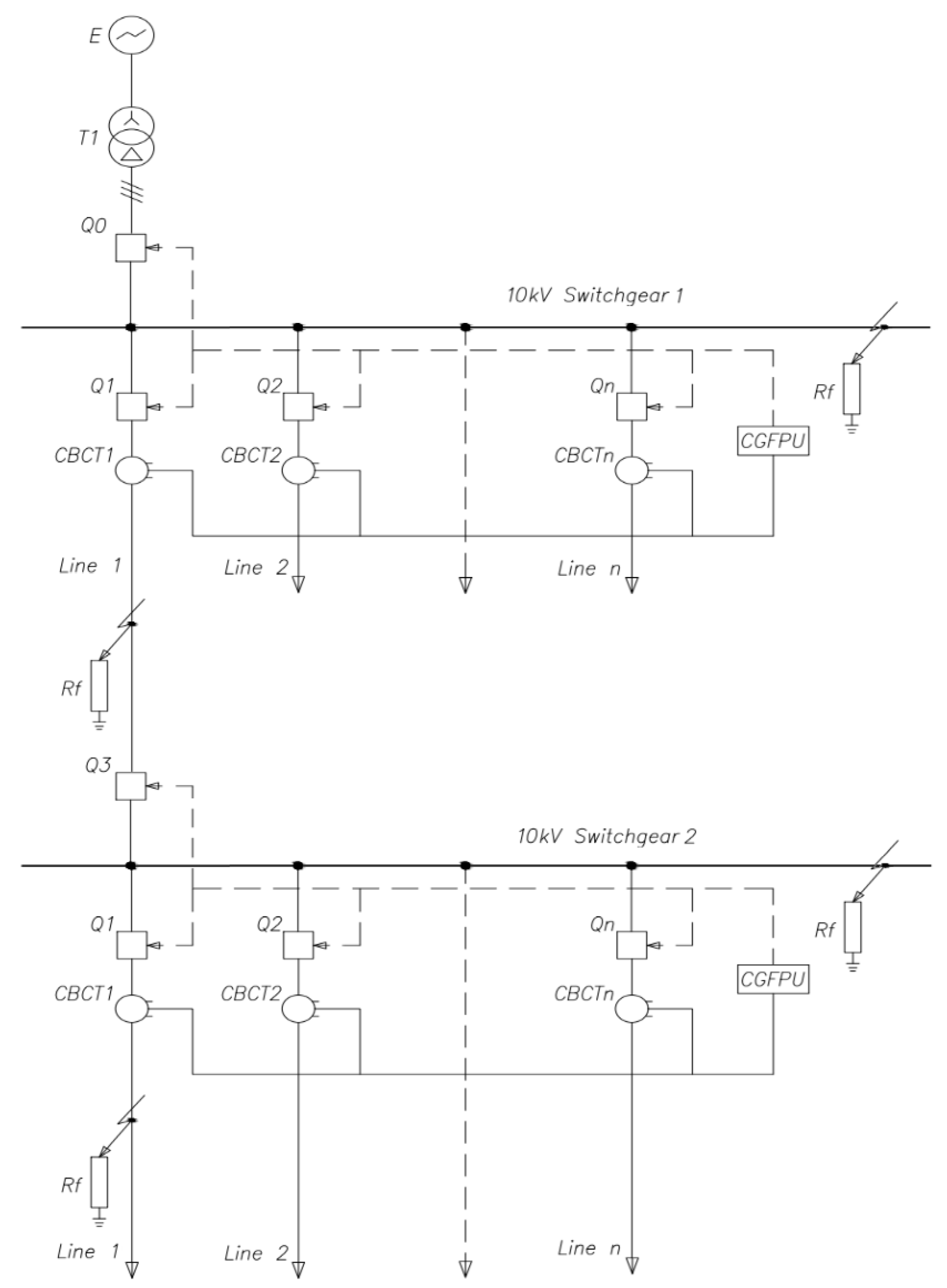
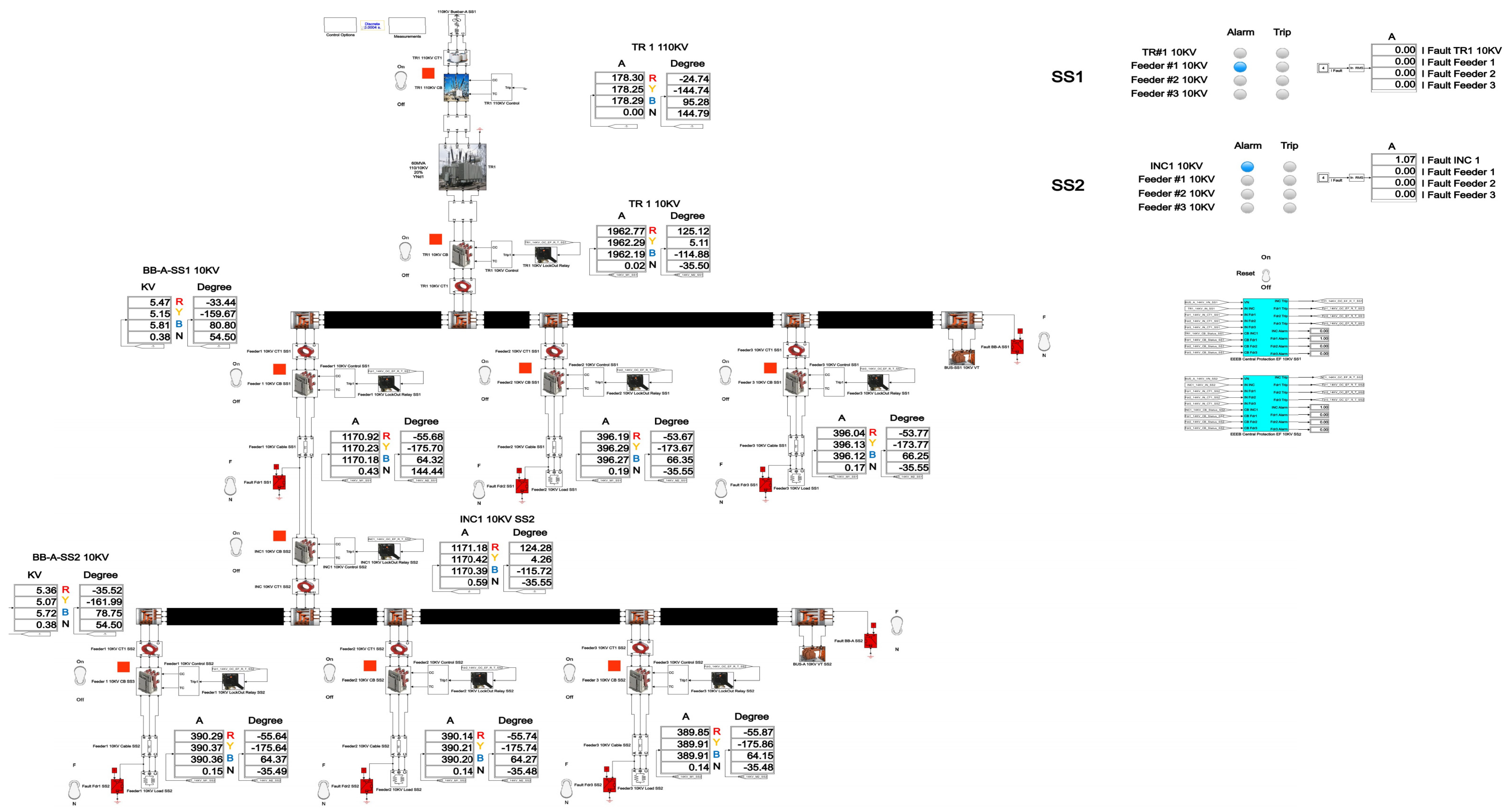
Single-line diagram of a 110/10 kV Substation in the network with the isolated neutral configuration.
Figure 23.
Single-line diagram of a 110/10 kV Substation in the network with the isolated neutral configuration.
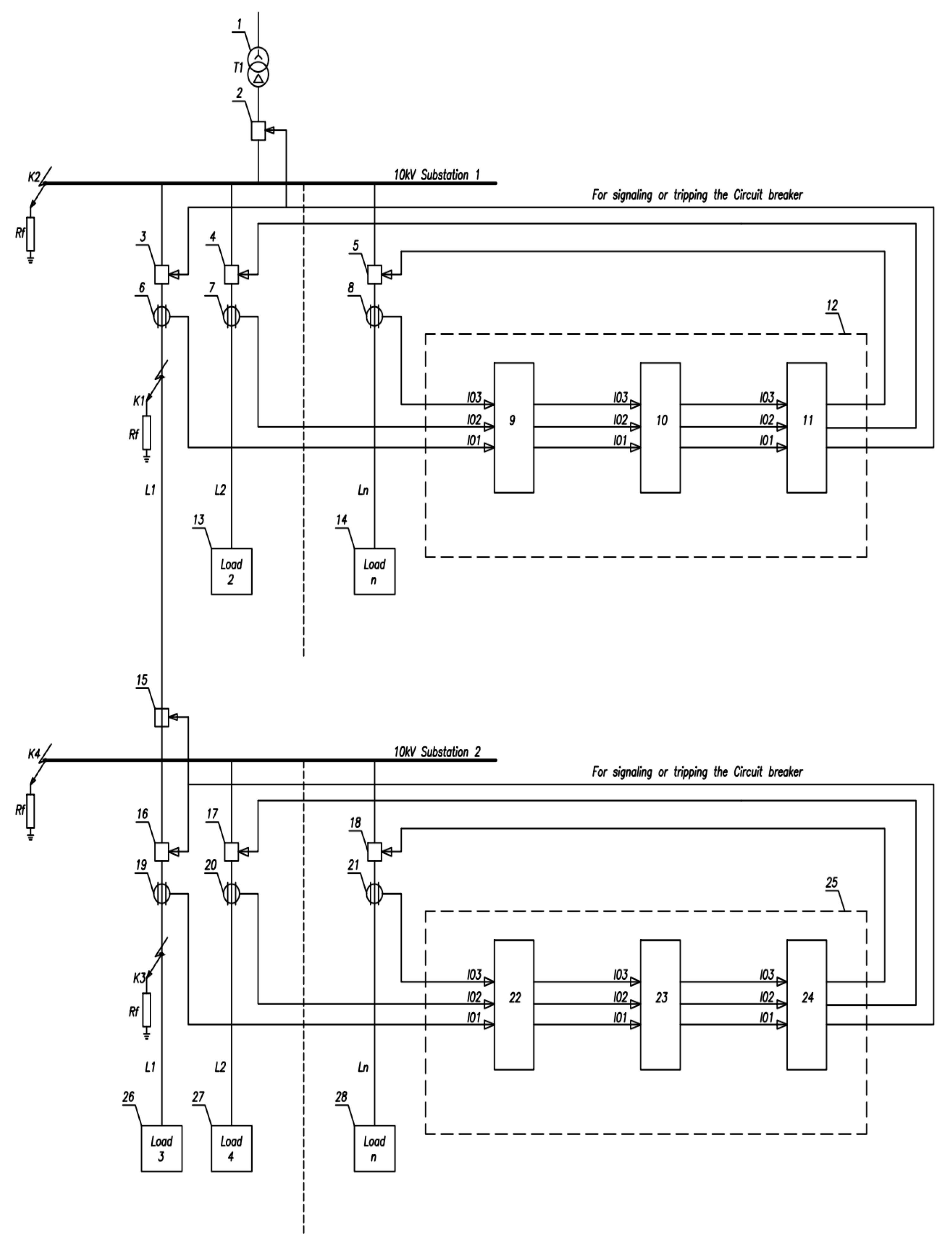
Figure 24.
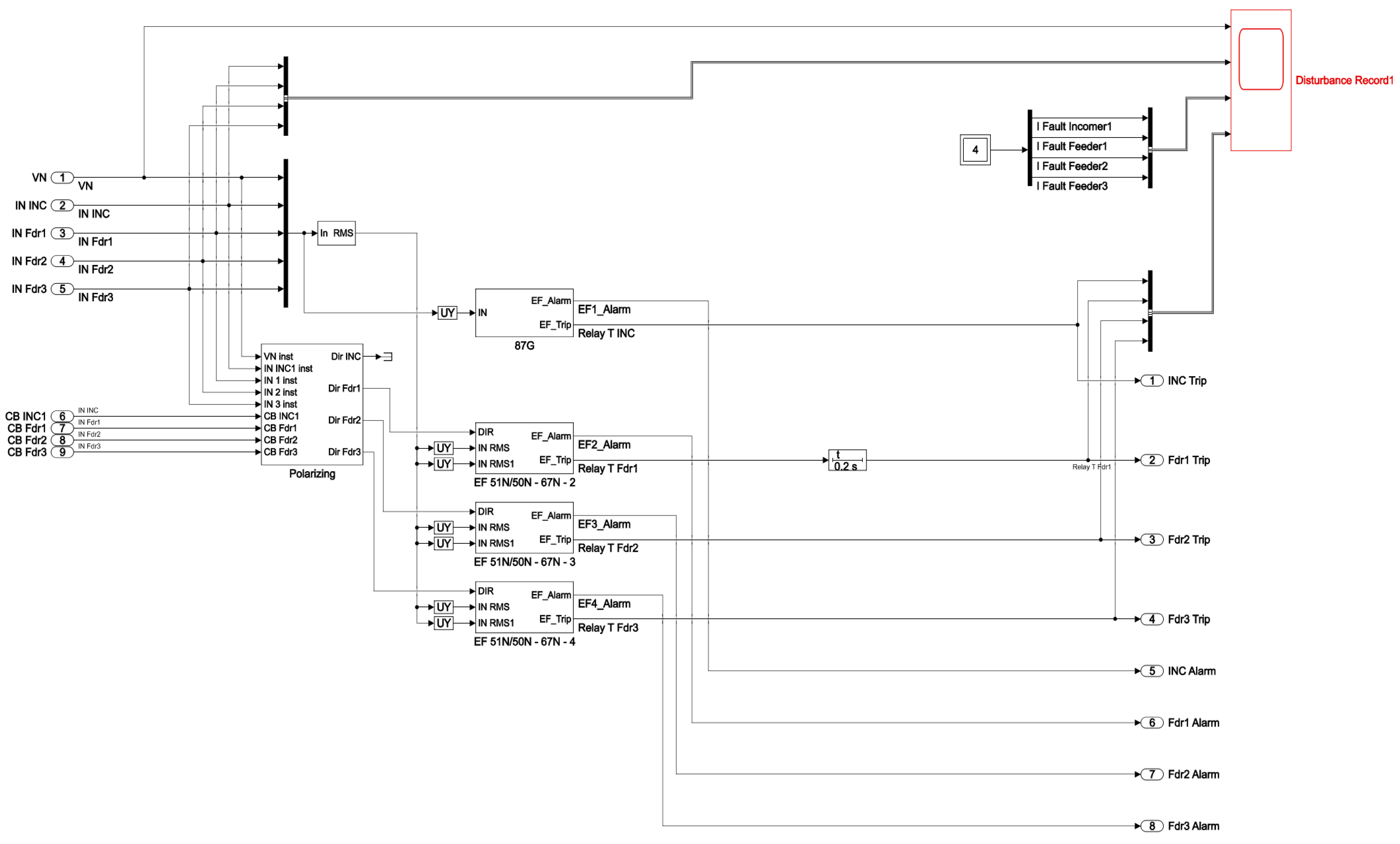
Block diagram of the CGFPU in a 10 kV network with the isolated neutral configuration for the Substations No.1 and No.2.
Figure 24.
Block diagram of the CGFPU in a 10 kV network with the isolated neutral configuration for the Substations No.1 and No.2.
Figure 25.
Functional diagram of the CGFPU polarization module in the 10 kV network with the isolated neutral configuration for the Substation No.1 and No.2.
Figure 25.
Functional diagram of the CGFPU polarization module in the 10 kV network with the isolated neutral configuration for the Substation No.1 and No.2.
Figure 26.
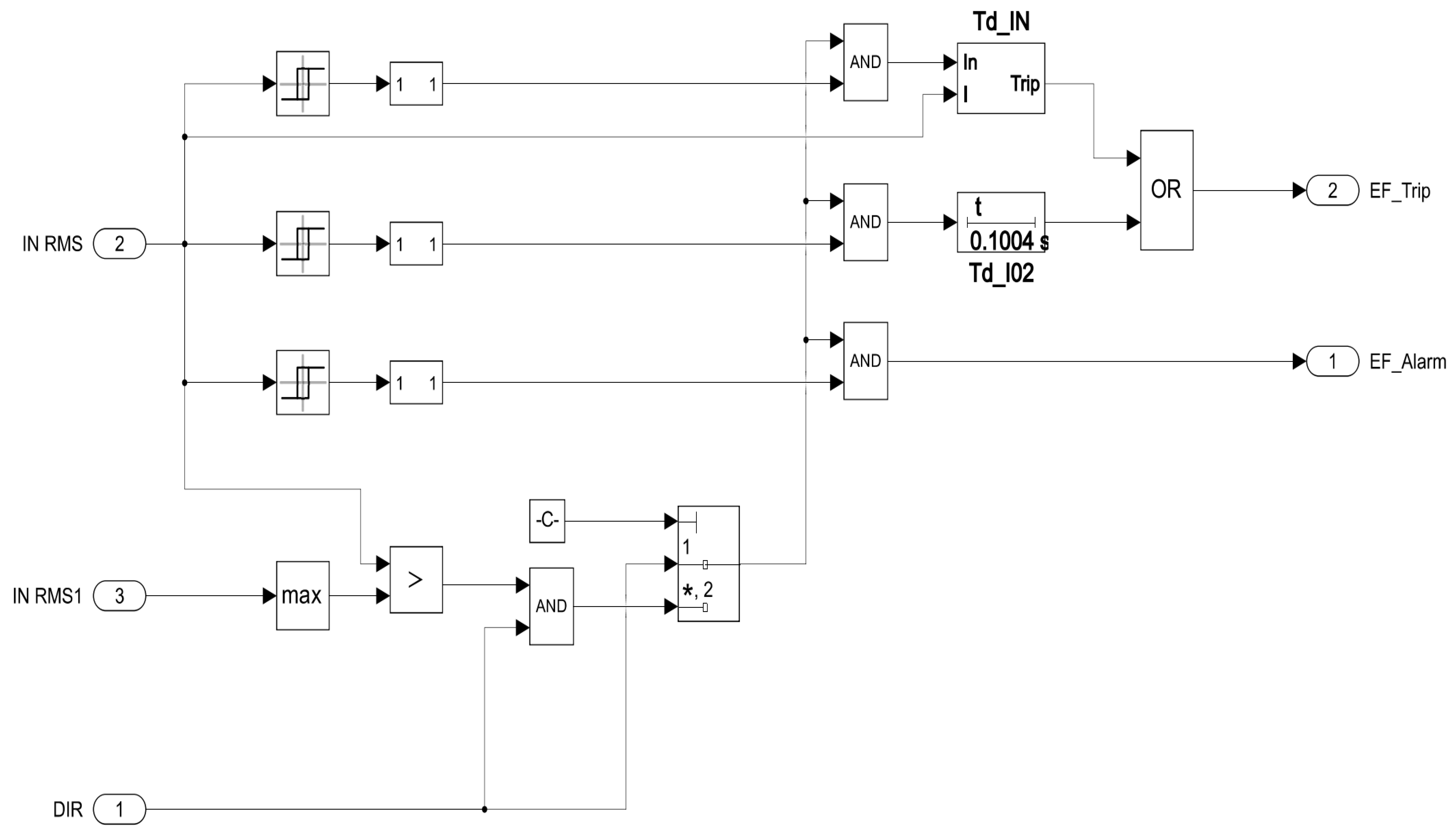
Functional diagram of the angle and magnitude comparison module for Feeders No.1, 2, and 3 in the Substations No.1 and No.2.
Figure 26.
Functional diagram of the angle and magnitude comparison module for Feeders No.1, 2, and 3 in the Substations No.1 and No.2.
Figure 27.
Functional diagram of the magnitude and angle comparison module for the incomers in substations No.1 and No.2.
Figure 27.
Functional diagram of the magnitude and angle comparison module for the incomers in substations No.1 and No.2.
Figure 28.
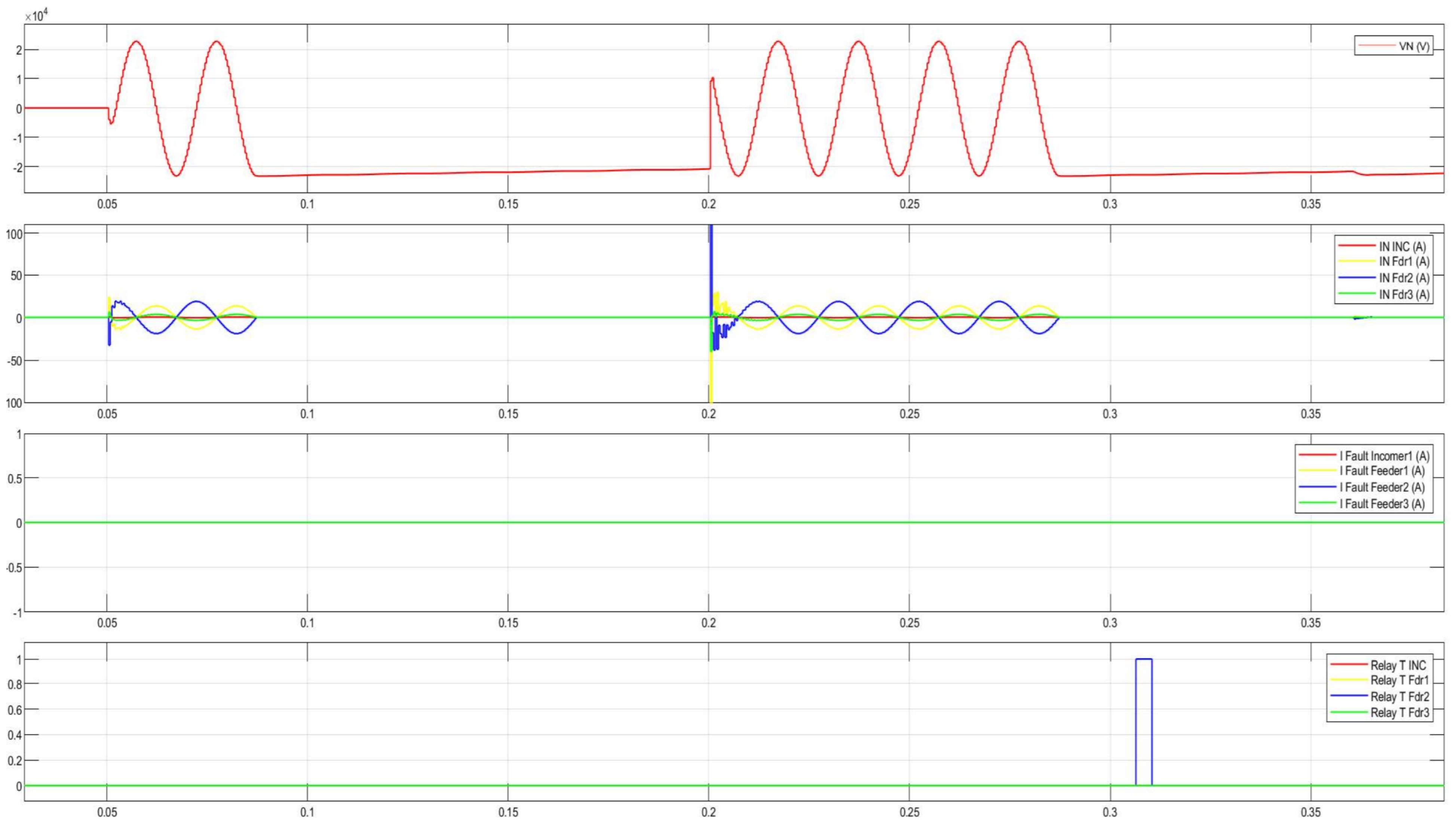
Disturbance record of the CGFPU issuing an alarm for single pulse arcing SPGF at 10 kV.
Figure 28.
Disturbance record of the CGFPU issuing an alarm for single pulse arcing SPGF at 10 kV.
Figure 29.
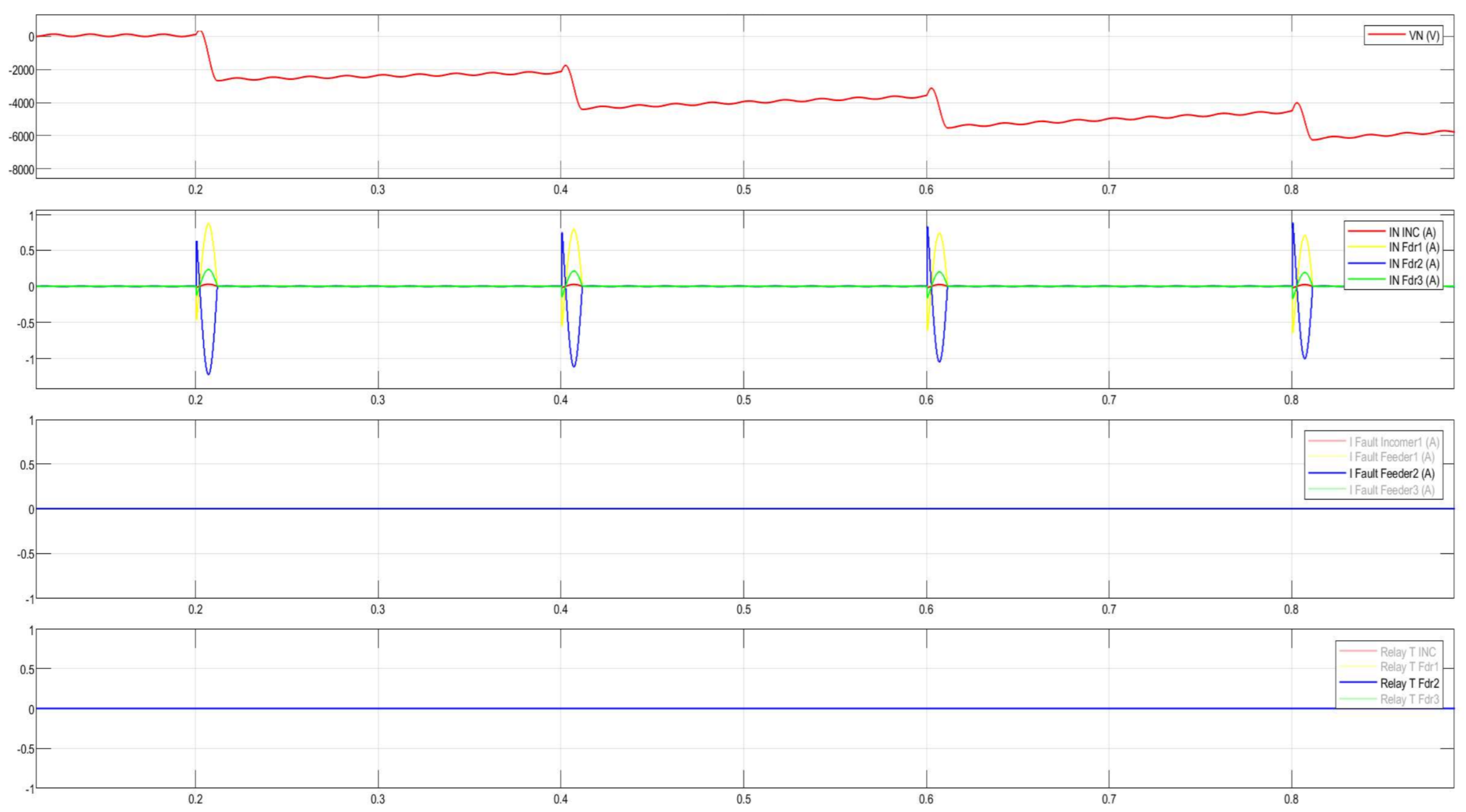
Disturbance record of the CGFPU issuing a trip signal during intermittent arcing SPGFs at 10 kV.
Figure 29.
Disturbance record of the CGFPU issuing a trip signal during intermittent arcing SPGFs at 10 kV.
Figure 30.
Flow diagram of the CGFPU.
Figure 30.
Flow diagram of the CGFPU.
Figure 31.
10 kV distribution network with the isolated neutral configuration.
Figure 31.
10 kV distribution network with the isolated neutral configuration.
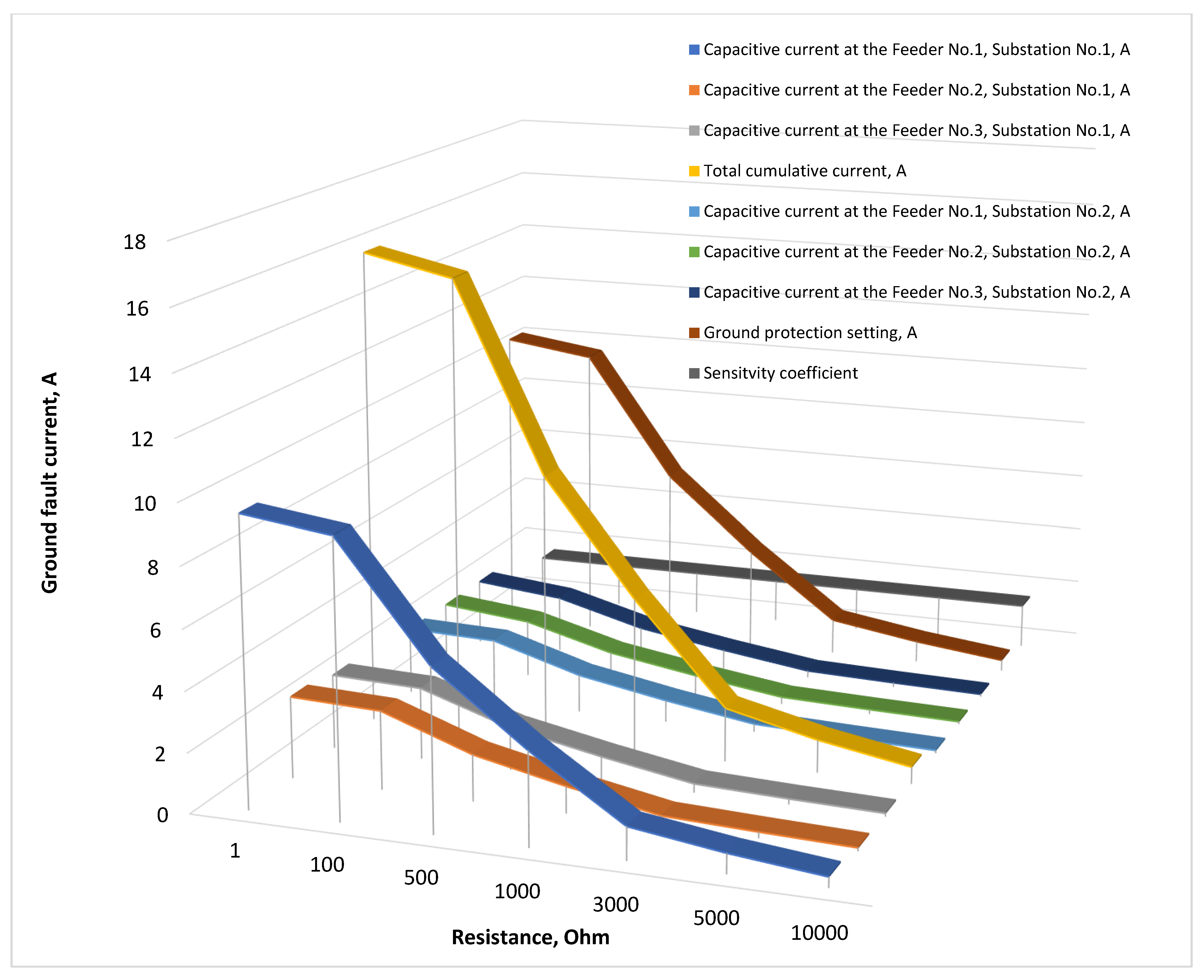
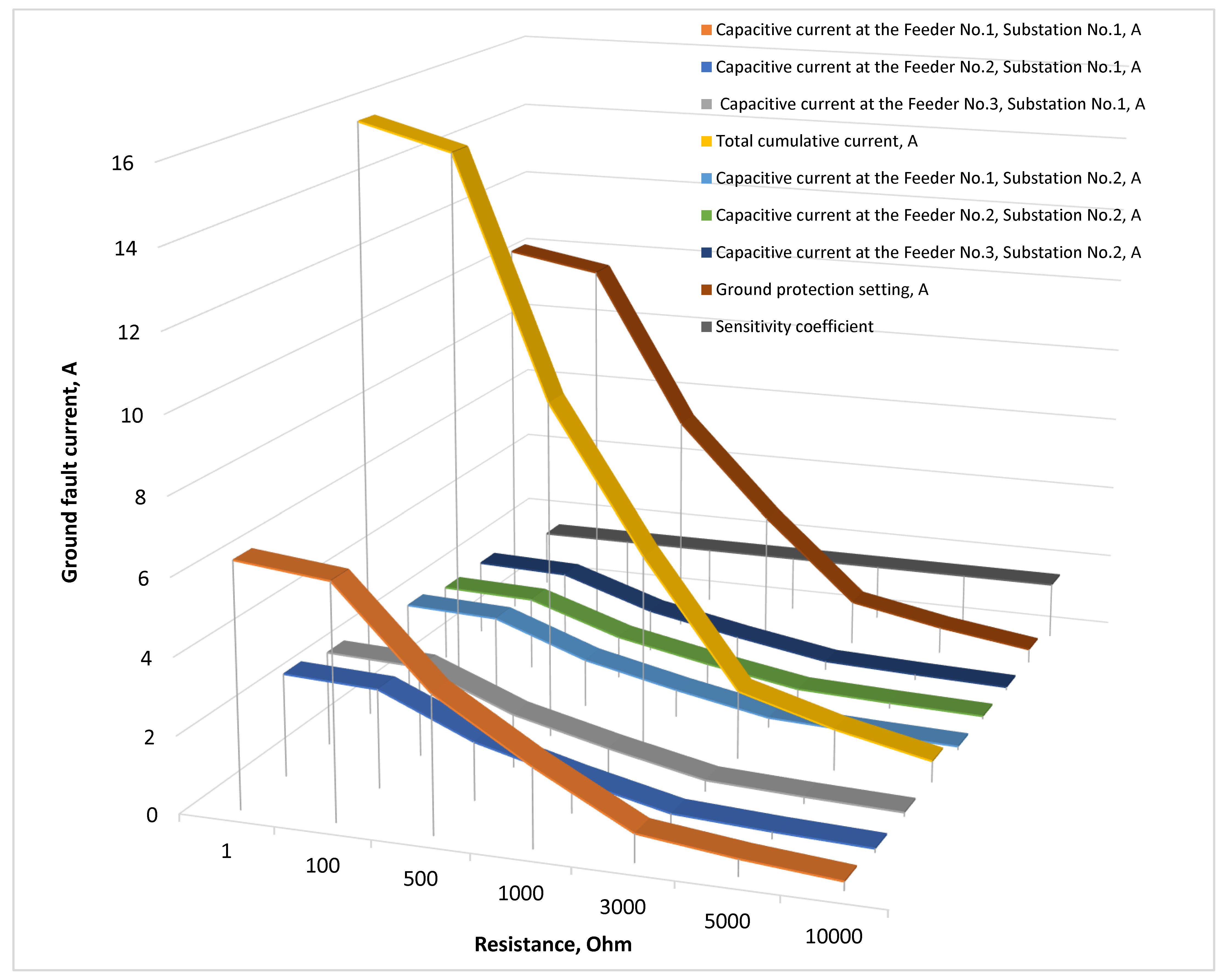
Figure 32.
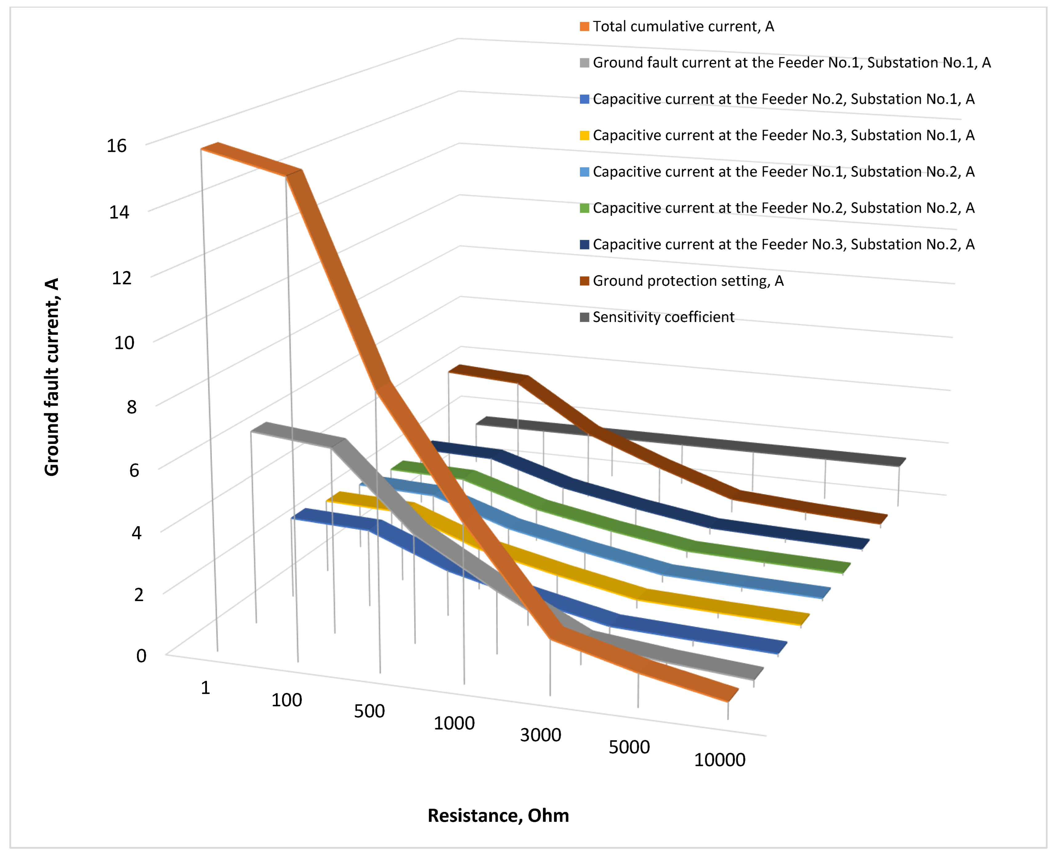
Total cumulative current, sensitivity ratio, ground fault current with transient resistances at the Feeder No.1, Substation No.1, and capacitive currents in the 10 kV network with the isolated neutral configuration.
Figure 32.
Total cumulative current, sensitivity ratio, ground fault current with transient resistances at the Feeder No.1, Substation No.1, and capacitive currents in the 10 kV network with the isolated neutral configuration.
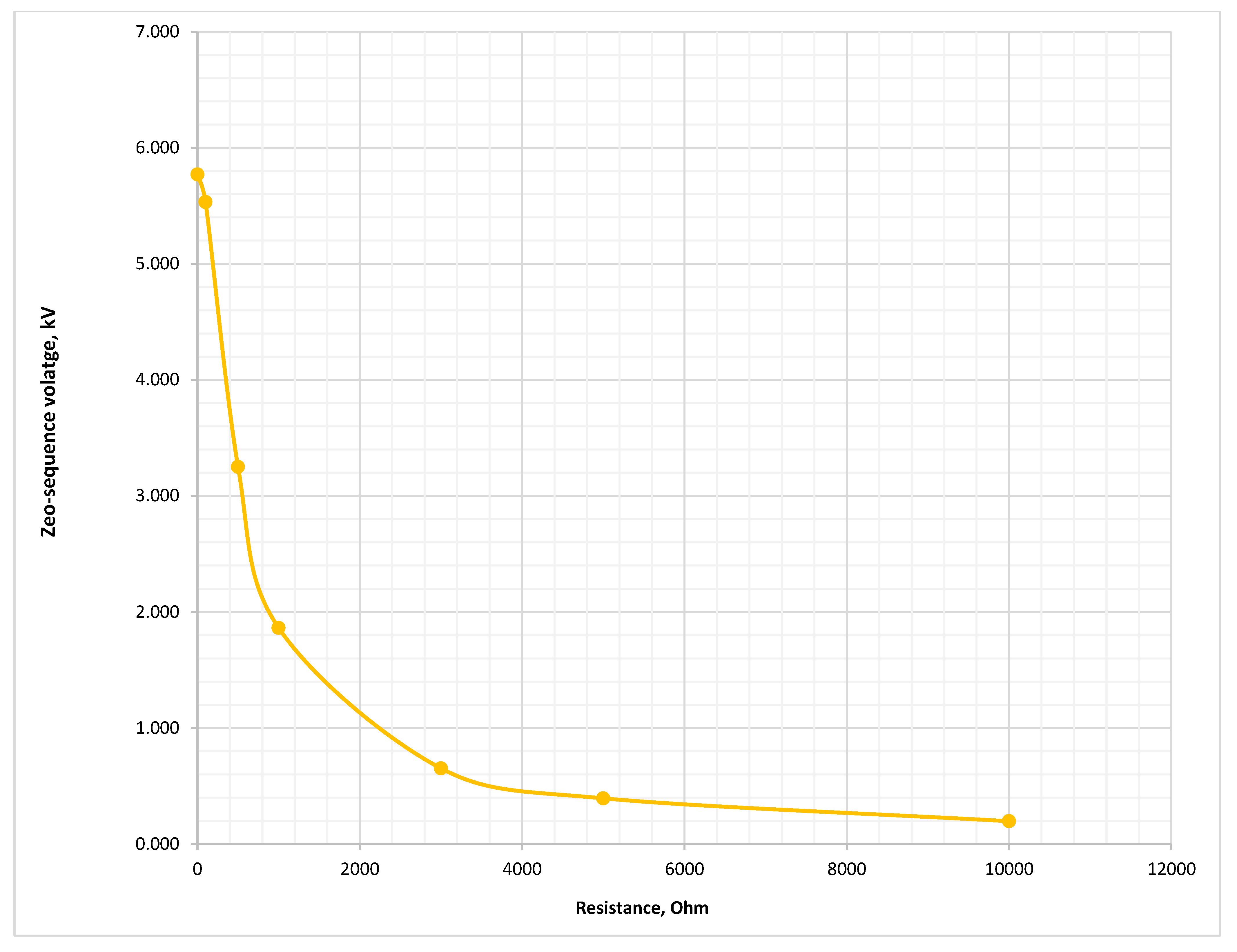
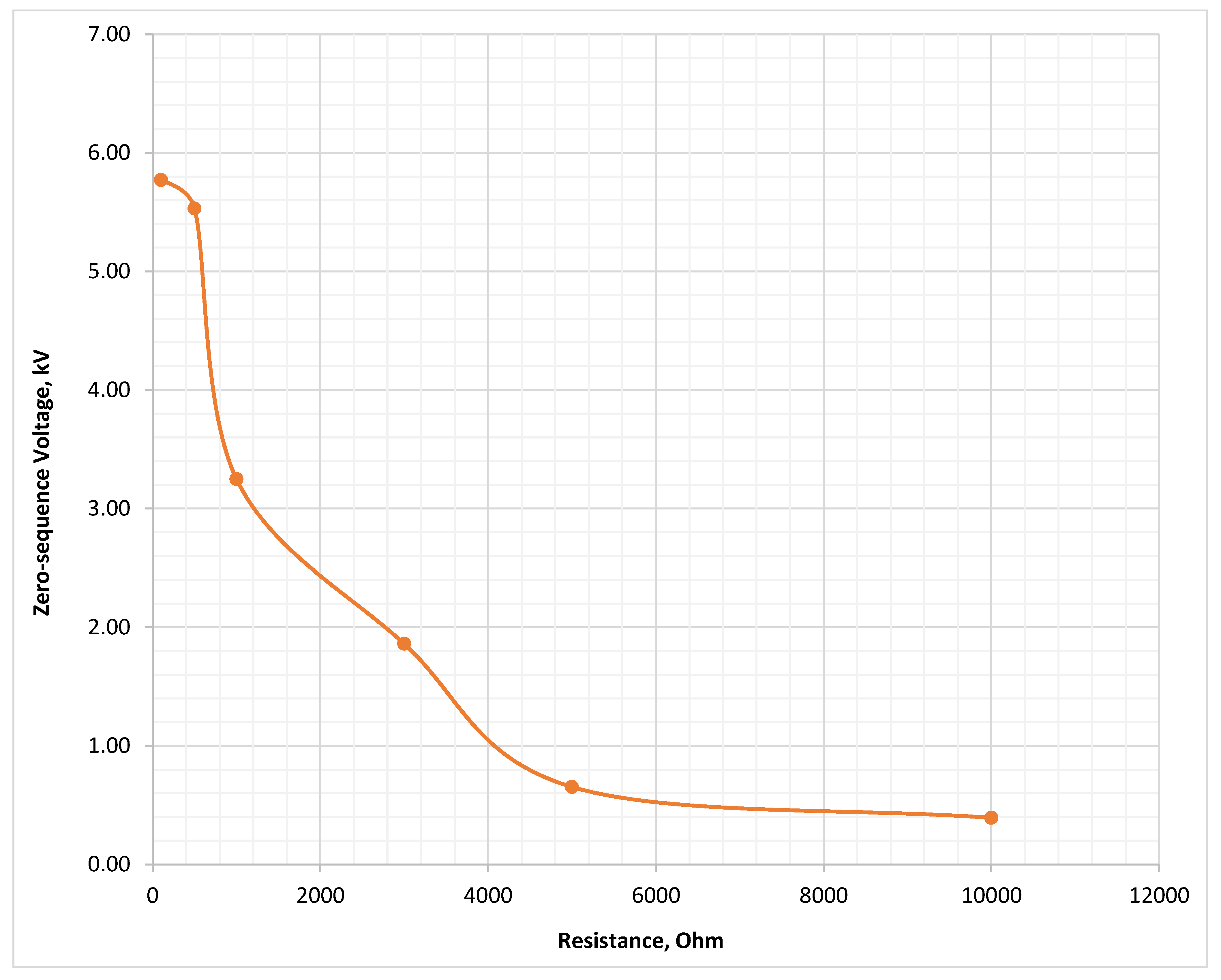
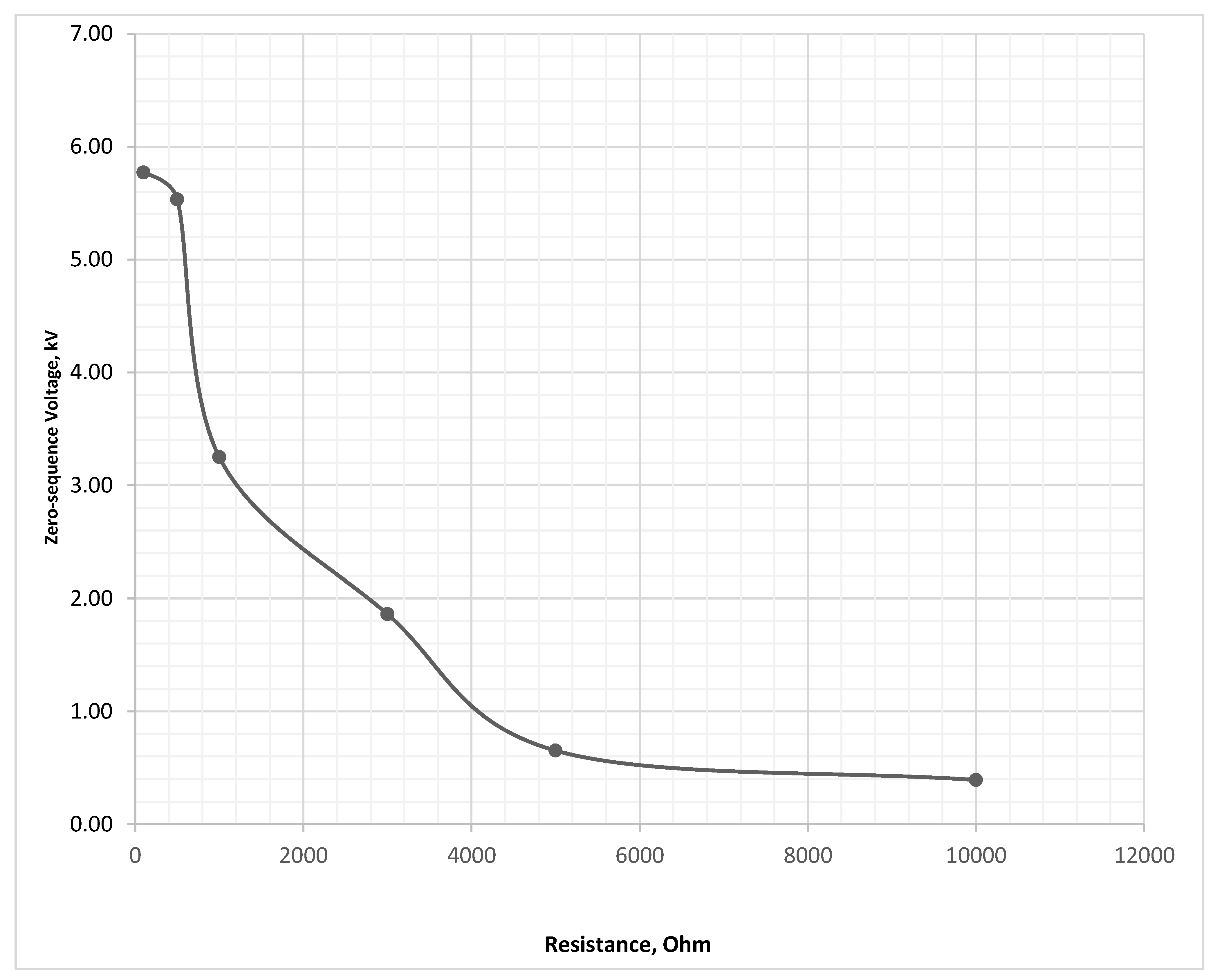
Figure 33.
Zero-sequence voltage during SPGF with transient resistances at the Feeder No.1, Substation No.1 in the 10 kV network with the isolated neutral configuration.
Figure 33.
Zero-sequence voltage during SPGF with transient resistances at the Feeder No.1, Substation No.1 in the 10 kV network with the isolated neutral configuration.
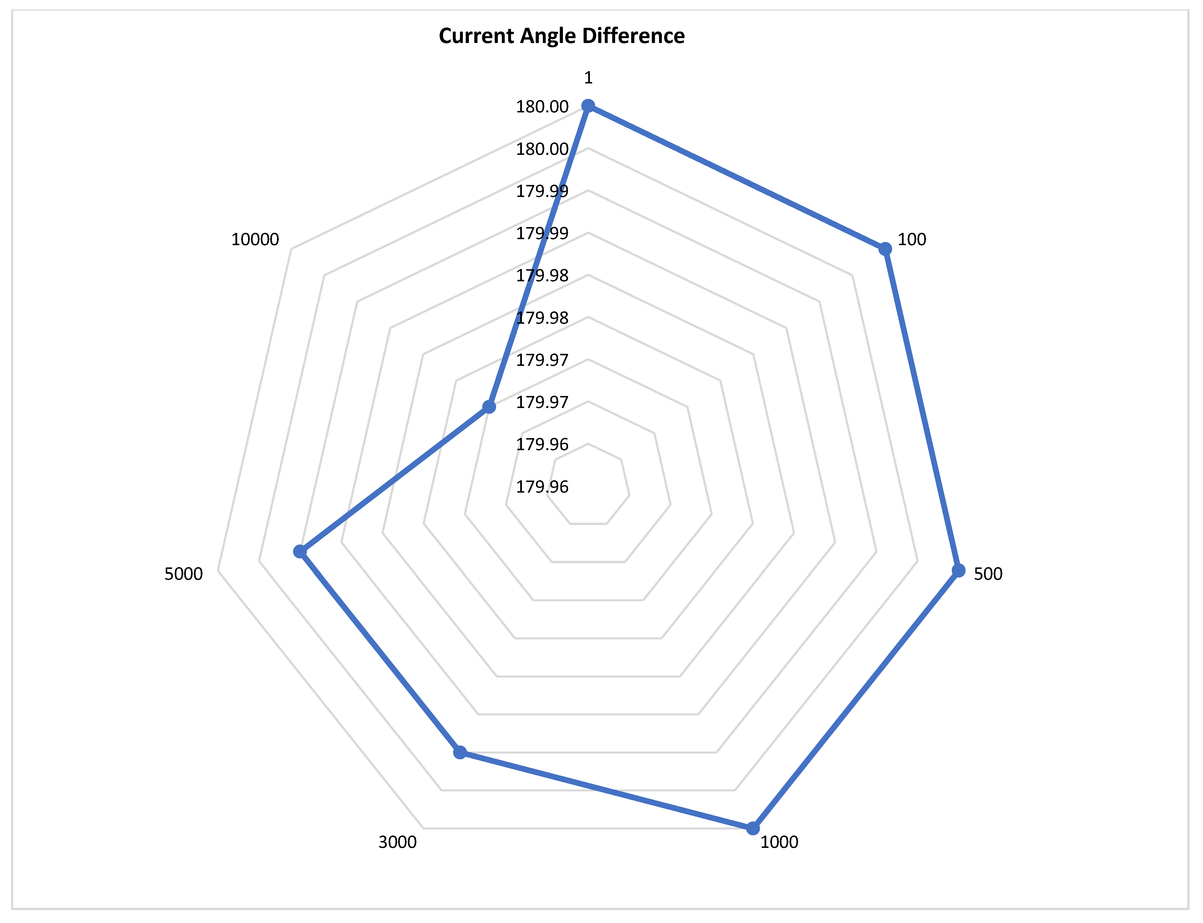
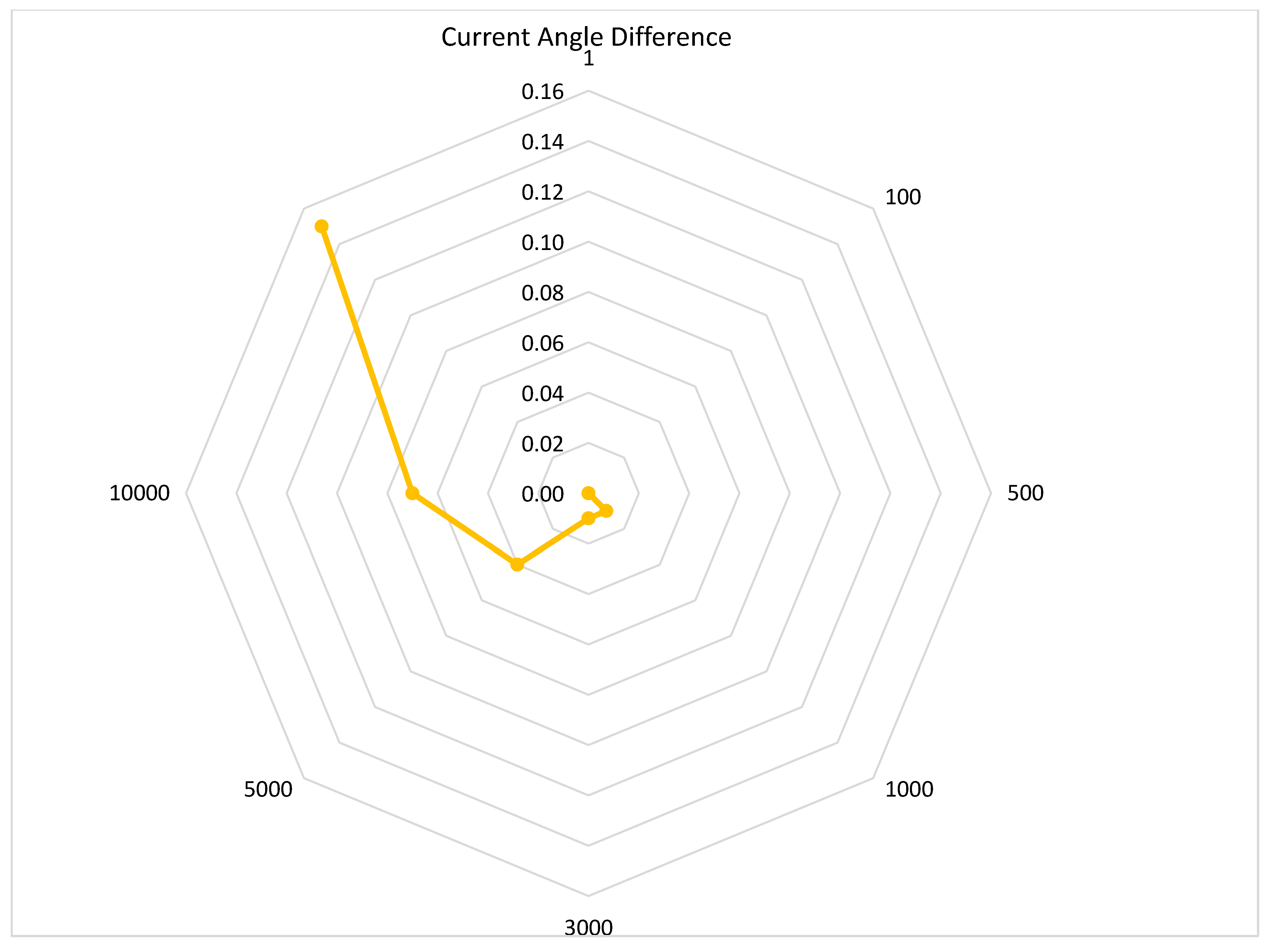
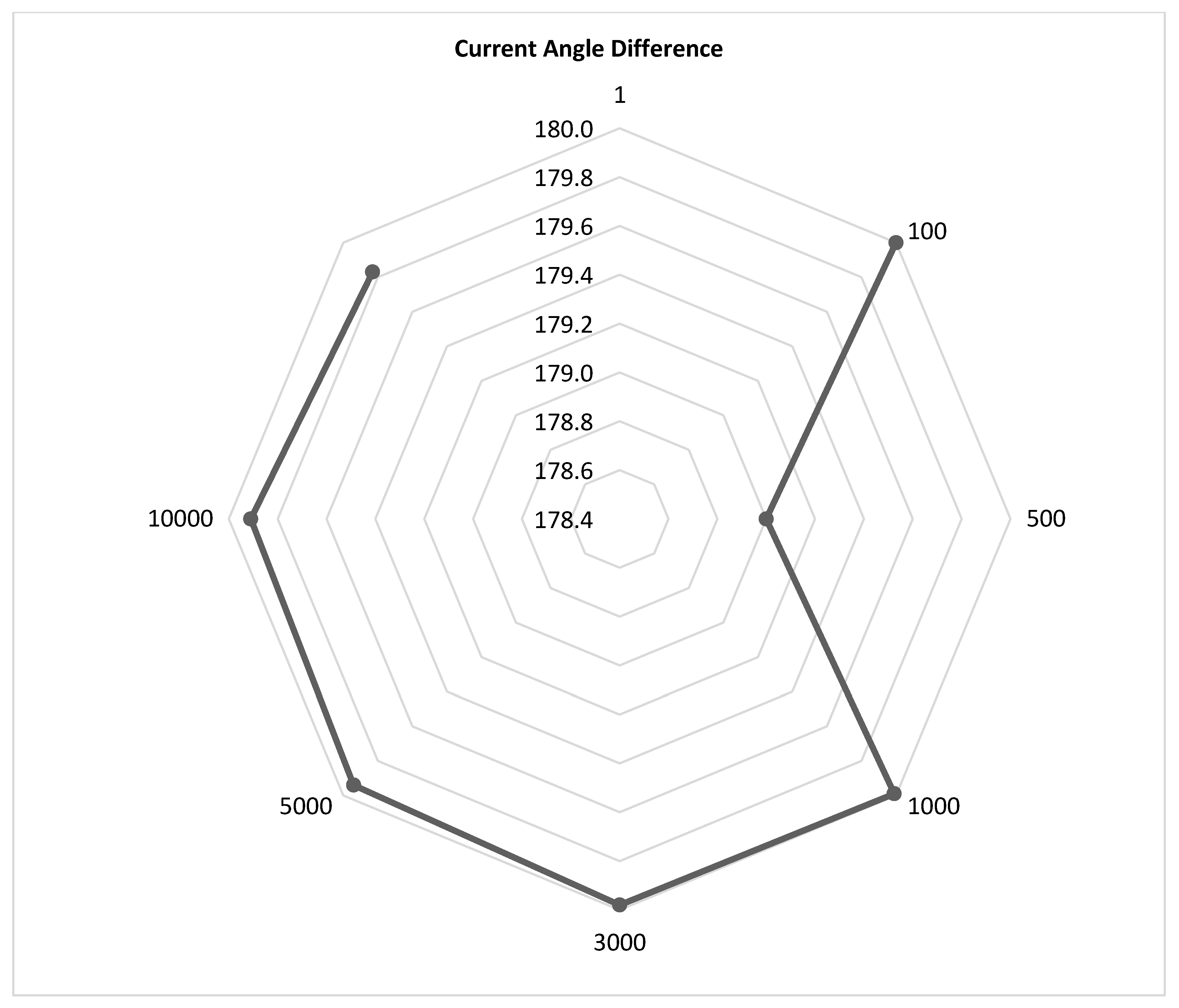
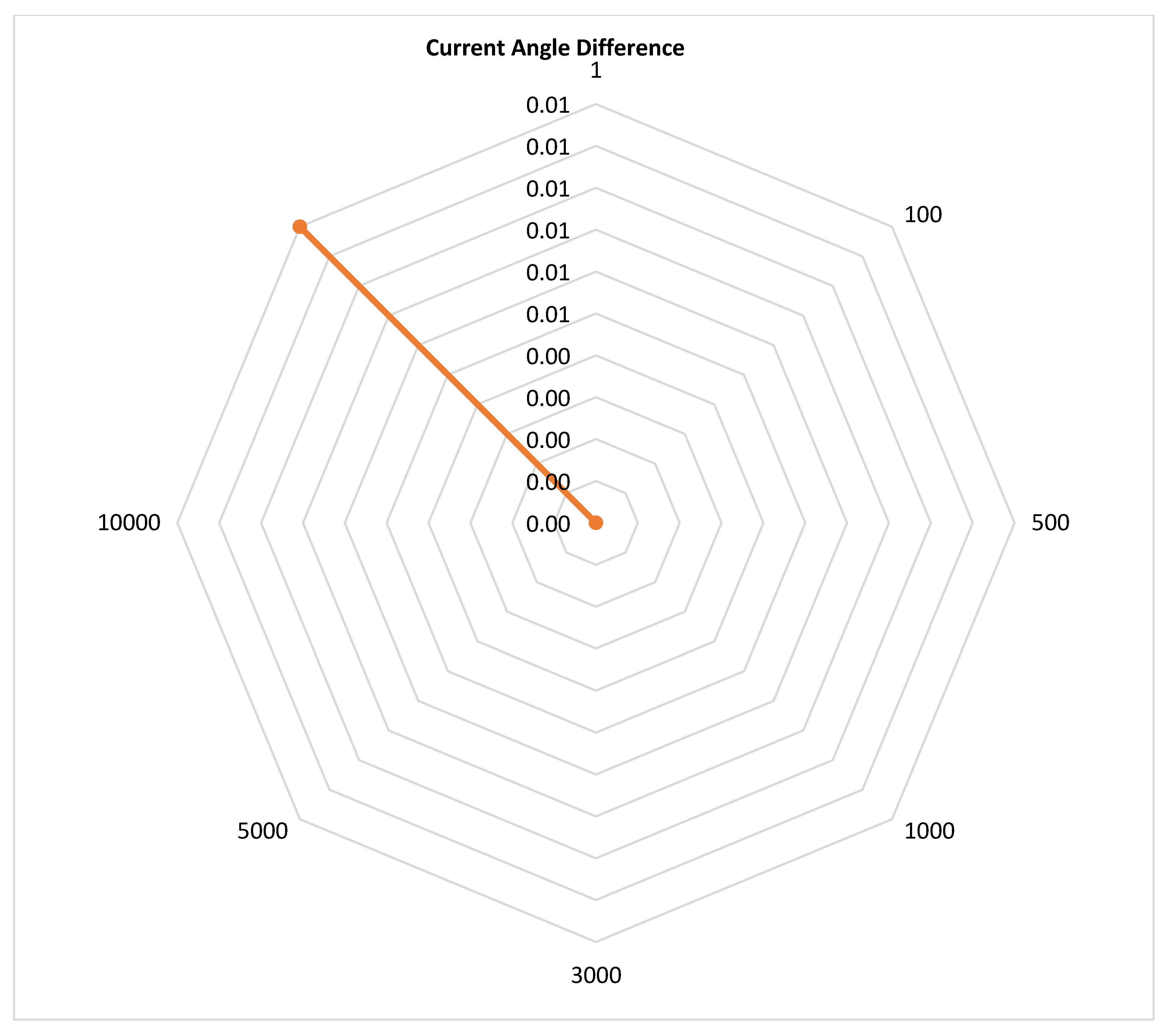
Figure 34.
Current angle difference during SPGF with transient resistance at the Feeder No.1, Substation No.1 in the 10 kV network with the isolated neutral configuration.
Figure 34.
Current angle difference during SPGF with transient resistance at the Feeder No.1, Substation No.1 in the 10 kV network with the isolated neutral configuration.
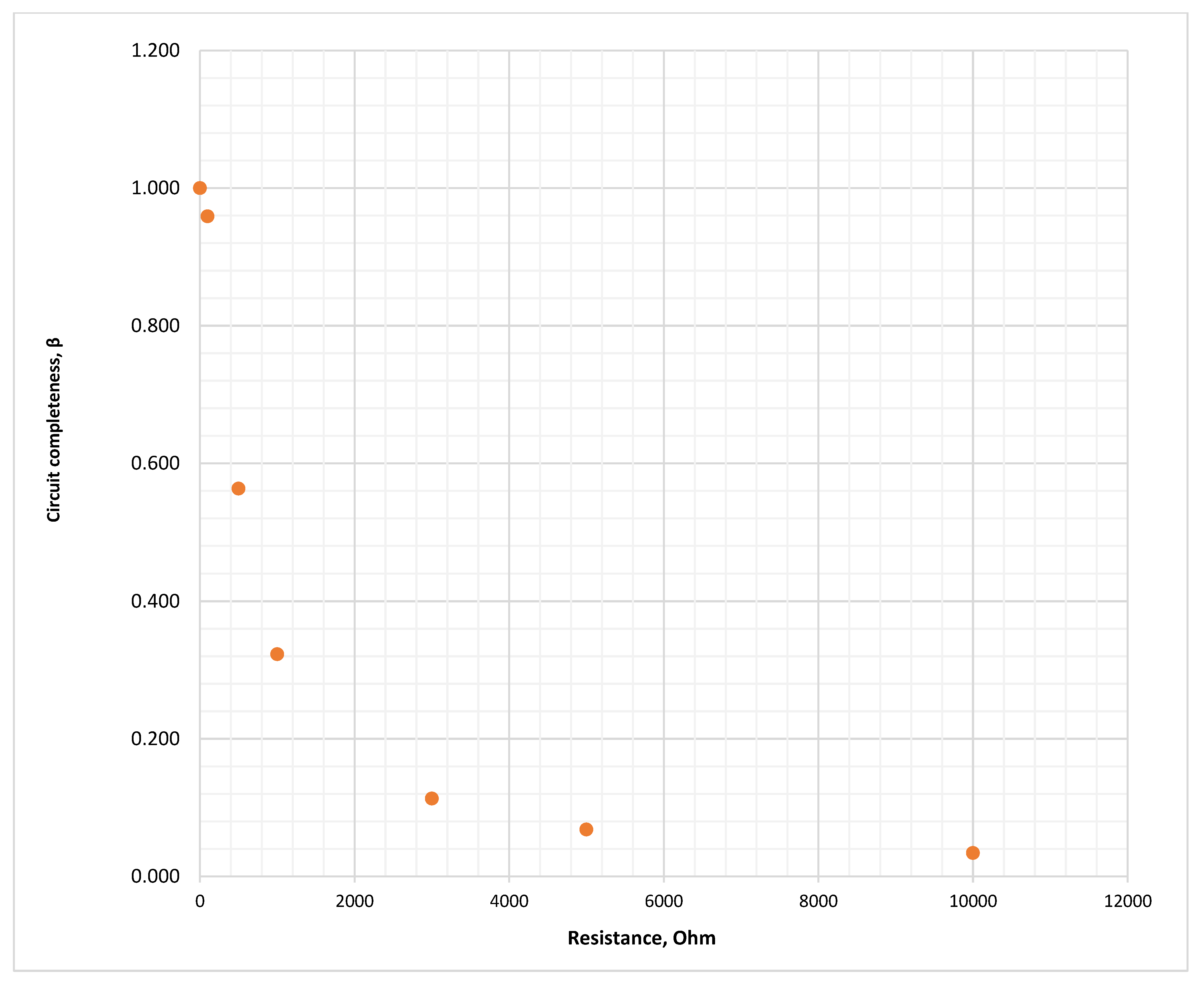
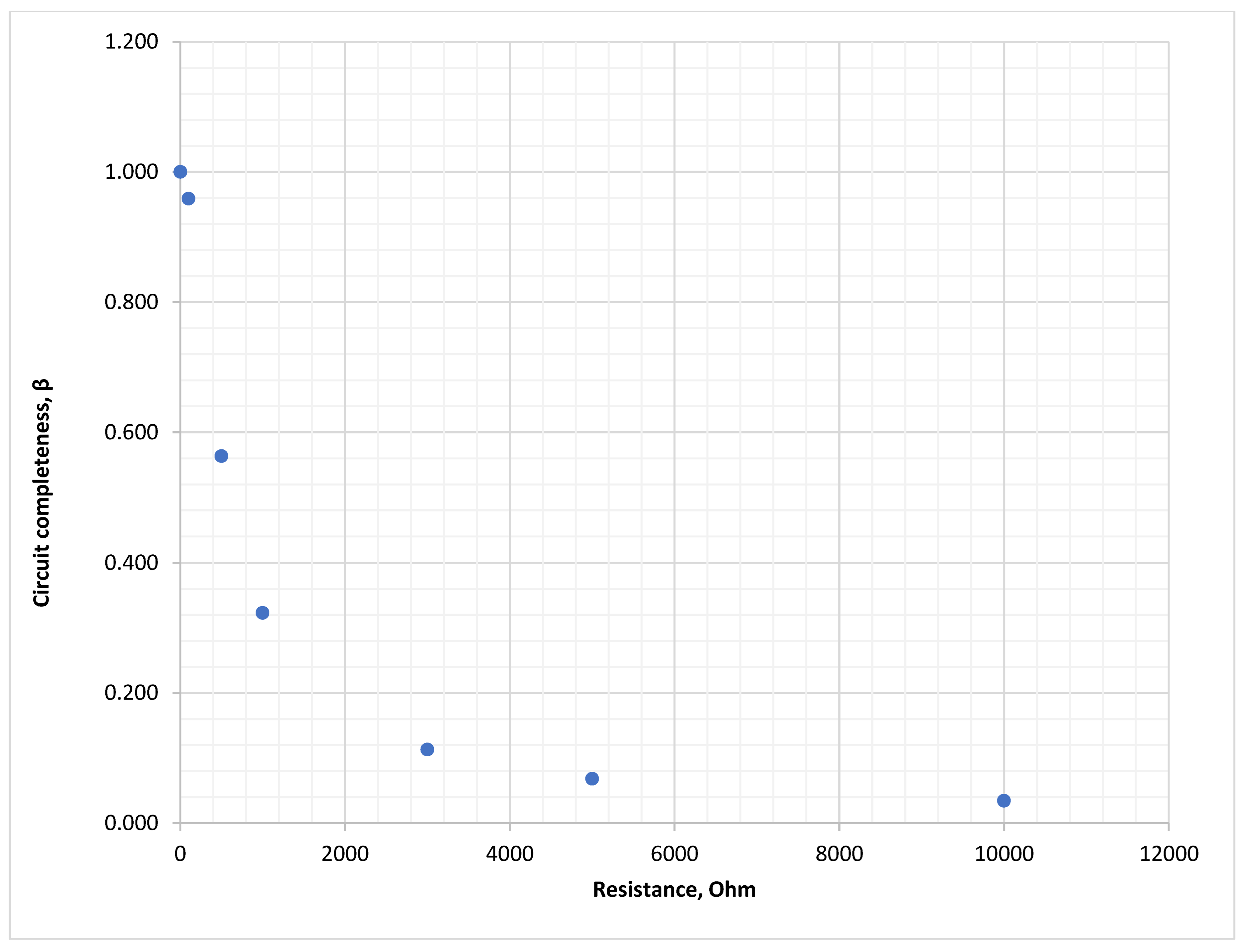
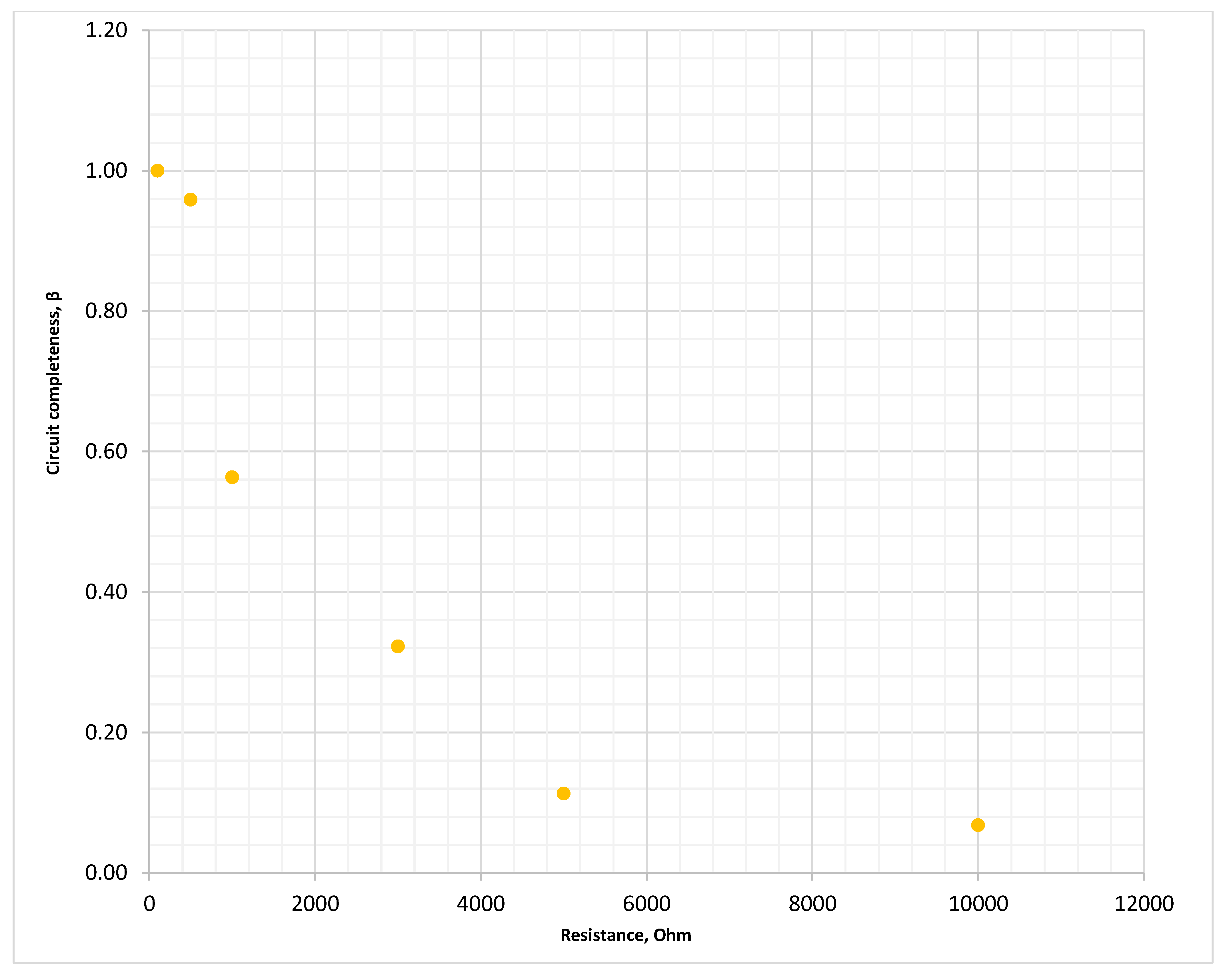
Figure 35.
Loop integrity coefficient during SPGF with transient resistances at Feeder No.1, Substation No.1 in the 10 kV isolated neutral network.
Figure 35.
Loop integrity coefficient during SPGF with transient resistances at Feeder No.1, Substation No.1 in the 10 kV isolated neutral network.
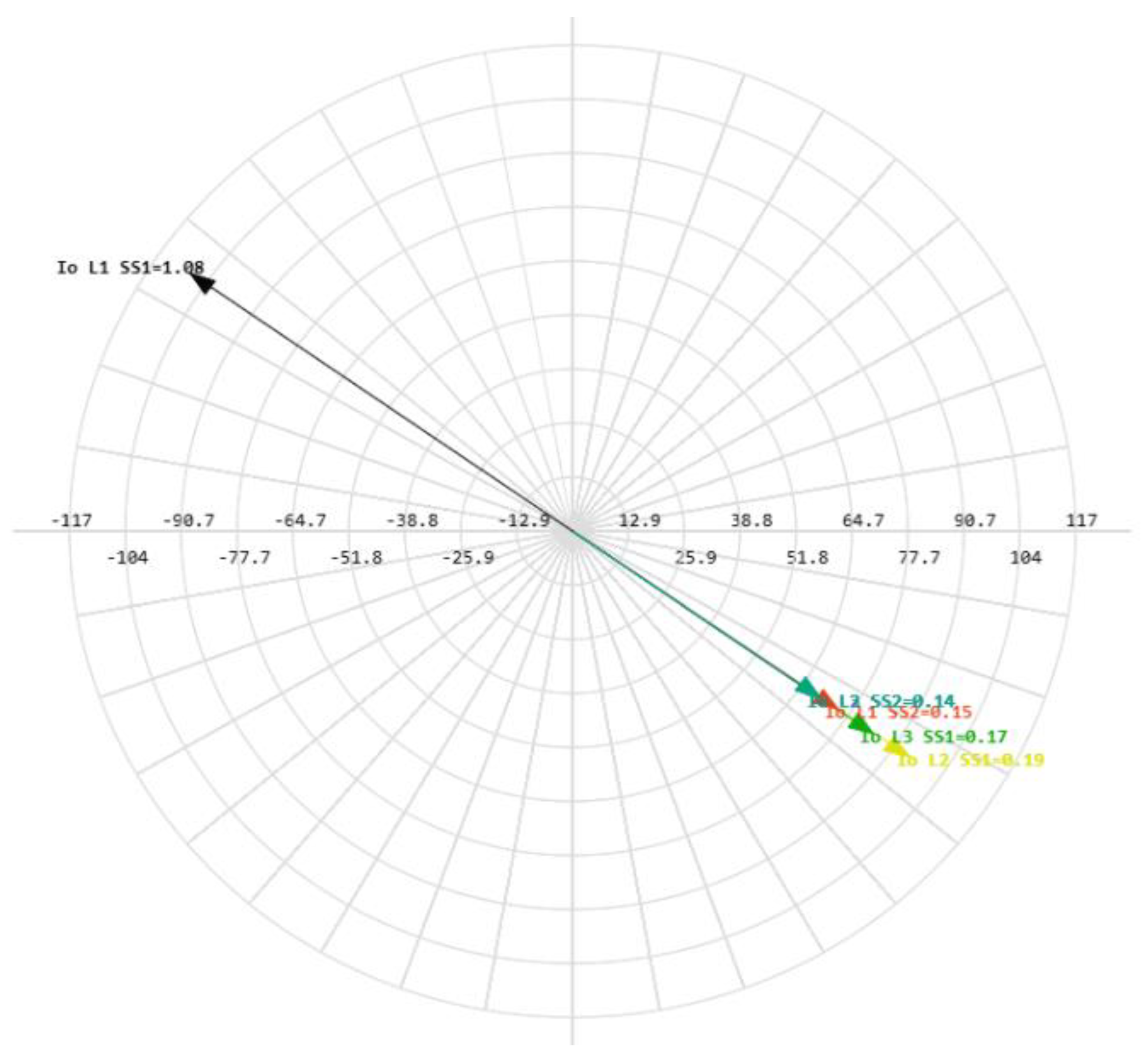
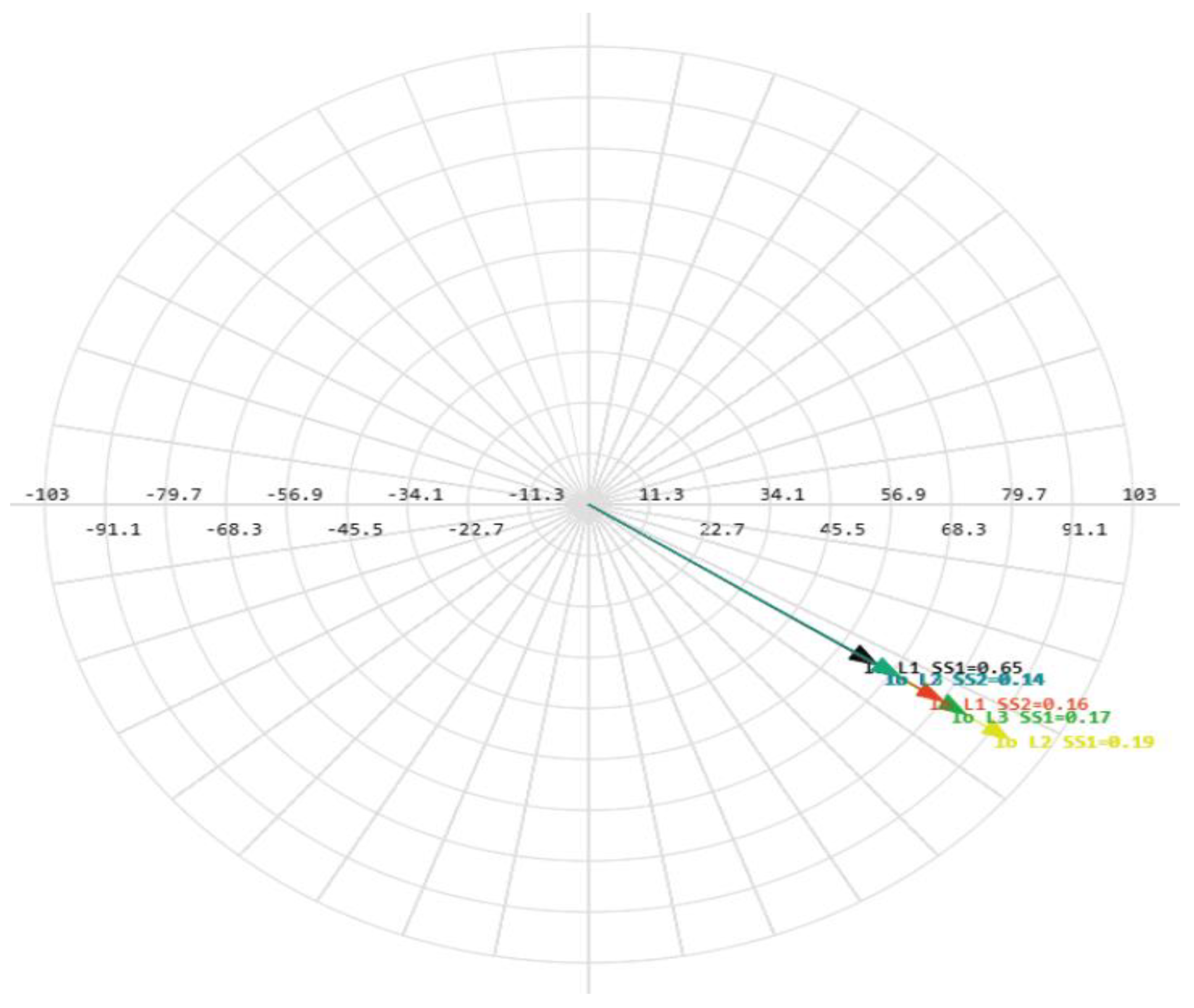
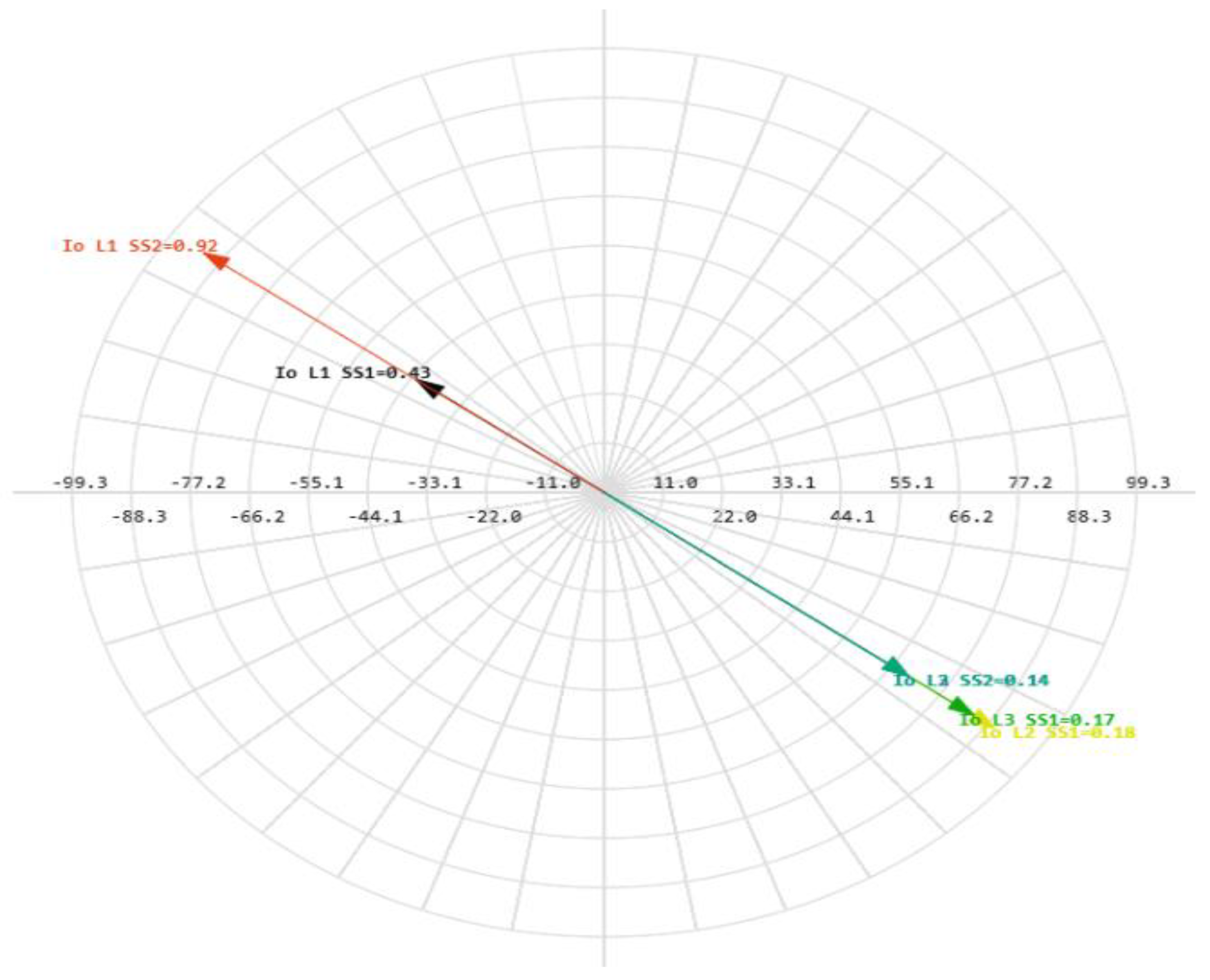
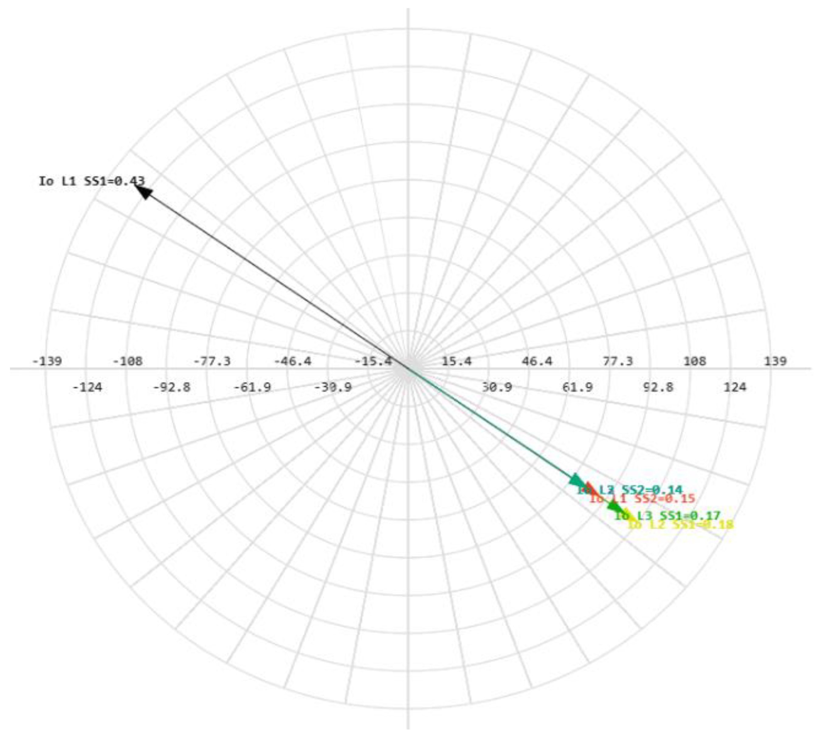
Figure 36.
Phasor diagram for SPGF at the Feeder No.1, Substation No.1 and capacitive currents in the 10 kV network with the isolated neutral configuration.
Figure 36.
Phasor diagram for SPGF at the Feeder No.1, Substation No.1 and capacitive currents in the 10 kV network with the isolated neutral configuration.
Figure 37.
Ground fault current with the transient resistance on the Substation No.1 bus and capacitive currents in the 10 kV network with the isolated neutral configuration.
Figure 37.
Ground fault current with the transient resistance on the Substation No.1 bus and capacitive currents in the 10 kV network with the isolated neutral configuration.
Figure 38.
Zero-sequence voltage during SPGF with transient resistances on the Substation No.1 bus in the 10 kV network with the isolated neutral configuration.
Figure 38.
Zero-sequence voltage during SPGF with transient resistances on the Substation No.1 bus in the 10 kV network with the isolated neutral configuration.
Figure 39.
Current angle difference during SPGF with transient resistances on the Substation No.1 bus in the 10 kV network with the isolated neutral configuration.
Figure 39.
Current angle difference during SPGF with transient resistances on the Substation No.1 bus in the 10 kV network with the isolated neutral configuration.
Figure 40.
Loop integrity coefficient during SPGF with transient resistances on the Substation No.1 bus in the 10 kV network with the isolated neutral configuration.
Figure 40.
Loop integrity coefficient during SPGF with transient resistances on the Substation No.1 bus in the 10 kV network with the isolated neutral configuration.
Figure 41.
Phasor diagram for the SPGF on the Substation No.1 bus and capacitive currents in the 10 kV network with the isolated neutral configuration.
Figure 41.
Phasor diagram for the SPGF on the Substation No.1 bus and capacitive currents in the 10 kV network with the isolated neutral configuration.
Figure 42.
SPGF with transient resistance at the Feeder No.1, Substation No.2, and capacitive currents in the 10 kV network with the isolated neutral configuration.
Figure 42.
SPGF with transient resistance at the Feeder No.1, Substation No.2, and capacitive currents in the 10 kV network with the isolated neutral configuration.
Figure 43.
Zero-sequence voltage during SPGF with transient resistance at the Feeder No.1, Substation No.2 in the 10 kV network with the isolated neutral configuration.
Figure 43.
Zero-sequence voltage during SPGF with transient resistance at the Feeder No.1, Substation No.2 in the 10 kV network with the isolated neutral configuration.
Figure 44.
Current angle difference during SPGF with transient resistance at the Feeder No.1, Substation No.1 in the 10 kV network with the isolated neutral configuration.
Figure 44.
Current angle difference during SPGF with transient resistance at the Feeder No.1, Substation No.1 in the 10 kV network with the isolated neutral configuration.
Figure 45.
Loop integrity coefficient during SPGF with transient resistance at the Feeder No.1, Substation No.2 in the 10 kV network with the isolated neutral configuration.
Figure 45.
Loop integrity coefficient during SPGF with transient resistance at the Feeder No.1, Substation No.2 in the 10 kV network with the isolated neutral configuration.
Figure 46.
Phasor diagram for SPGF at the Feeder No.1, substation No.2, and capacitive currents in the 10 kV network with the isolated neutral configuration.
Figure 46.
Phasor diagram for SPGF at the Feeder No.1, substation No.2, and capacitive currents in the 10 kV network with the isolated neutral configuration.
Figure 47.
Ground fault current with the transient resistance on the Substation No.2 bus and capacitive currents in the 10 kV network with the isolated neutral configuration.
Figure 47.
Ground fault current with the transient resistance on the Substation No.2 bus and capacitive currents in the 10 kV network with the isolated neutral configuration.
Figure 48.
Zero-sequence voltage during SPGF with transient resistance on the Substation No.2 bus in the 10 kV network with the isolated neutral configuration.
Figure 48.
Zero-sequence voltage during SPGF with transient resistance on the Substation No.2 bus in the 10 kV network with the isolated neutral configuration.
Figure 49.
Current angle difference during SPGF with transient resistance on the Substation No.2 bus in the 10 kV network with the isolated neutral configuration.
Figure 49.
Current angle difference during SPGF with transient resistance on the Substation No.2 bus in the 10 kV network with the isolated neutral configuration.
Figure 50.
Loop integrity coefficient during SPGF with transient resistance on the Substation No.2 bus in the 10 kV network with the isolated neutral configuration.
Figure 50.
Loop integrity coefficient during SPGF with transient resistance on the Substation No.2 bus in the 10 kV network with the isolated neutral configuration.
Figure 51.
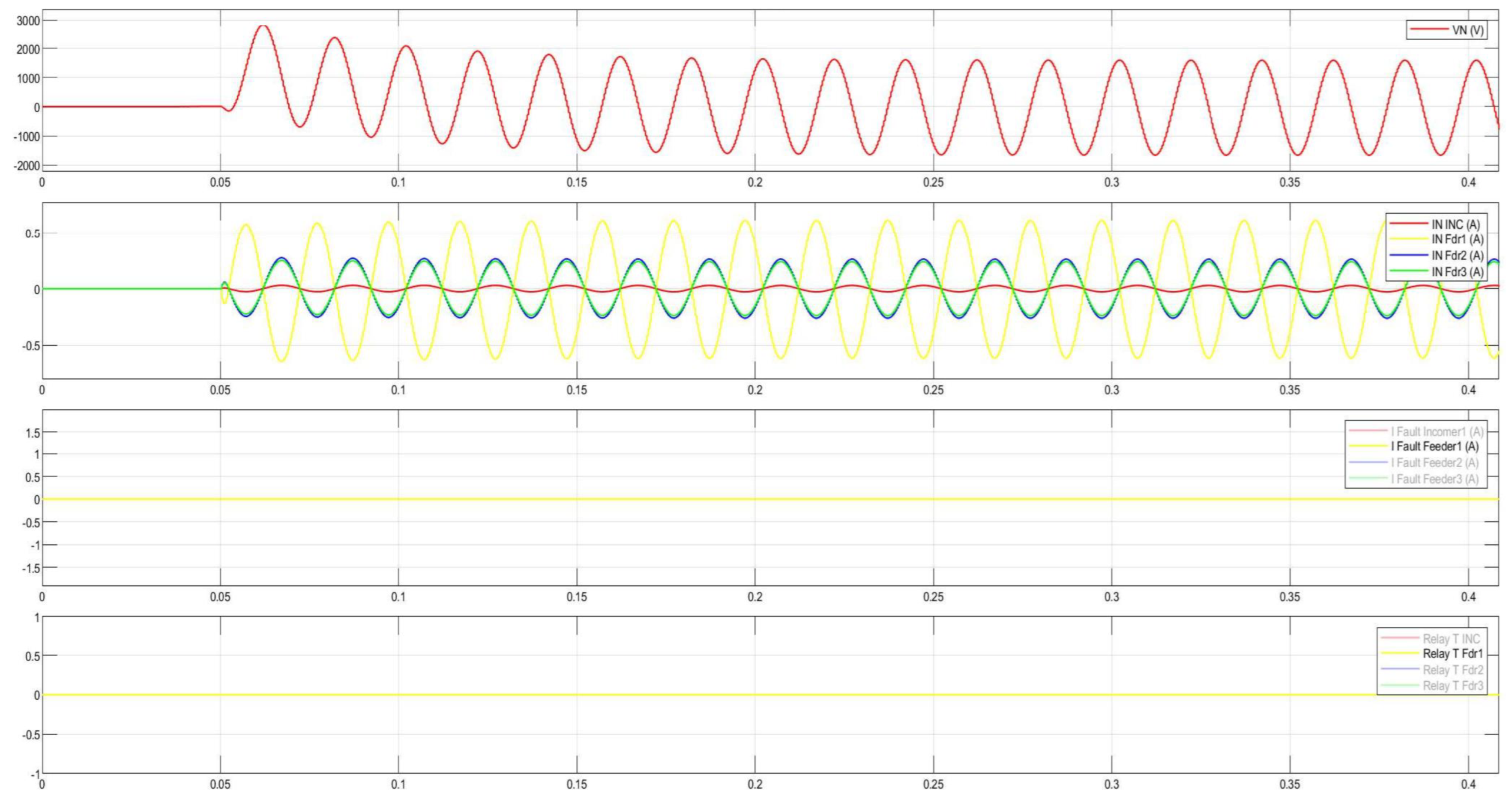
Phasor diagram for SPGF on the Substation No.2 bus and capacitive currents in the 10 kV network with the isolated neutral configuration. The minimum current in the secondary circuit that the ground overcurrent protection can detect depends on the relay sensitivity and the system configuration. Modern microprocessor relays can usually detect secondary currents of 0.01 to 0.05 A. For example, let us choose a transient resistance at the point of ground fault protection, Rf = 5000 Ohm. Let us calculate the ground overcurrent settings.
Figure 52.
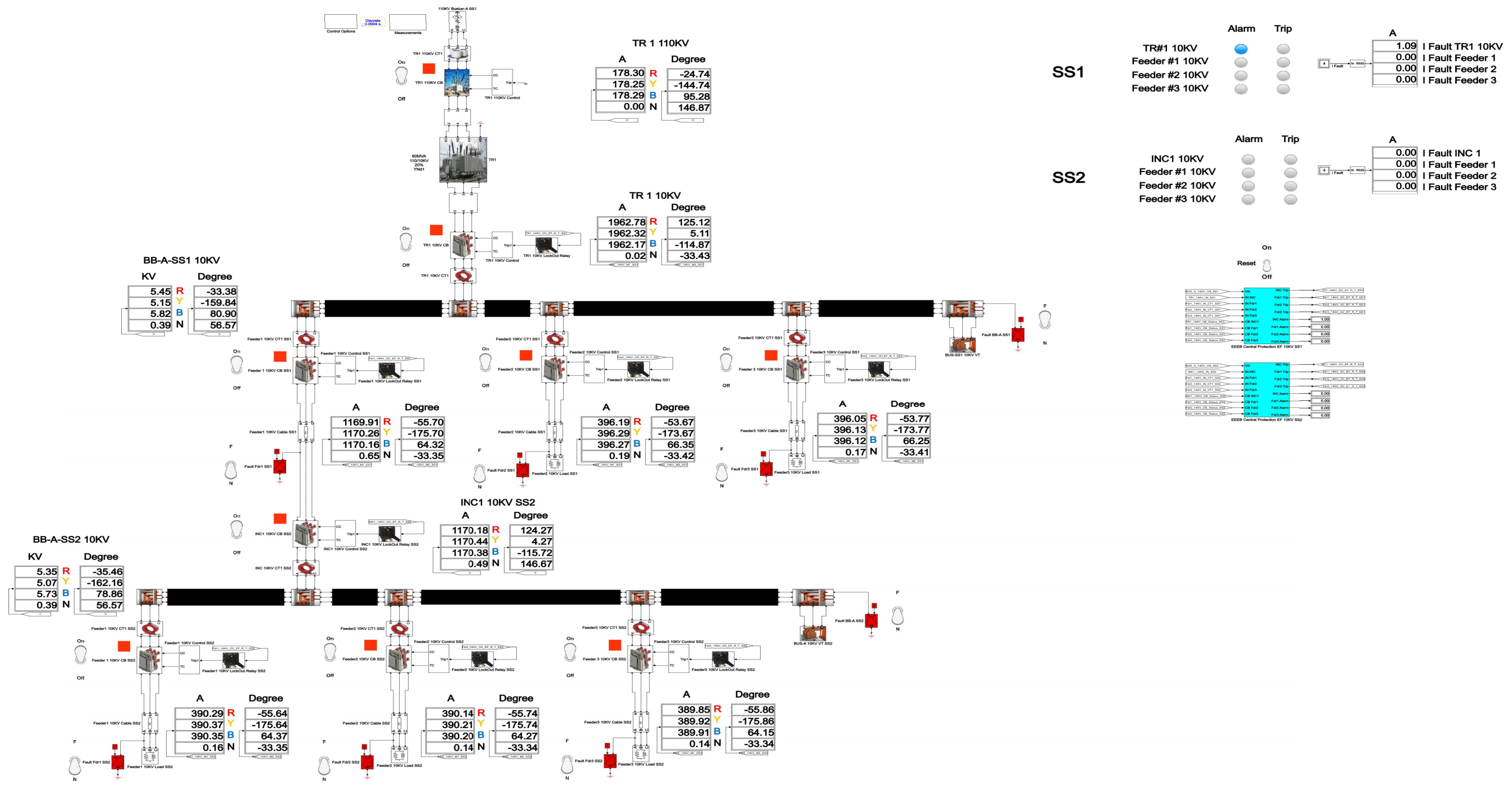
Single-line diagram with SPGF with the transient resistance of Rf = 5000 Ohm at the Feeder No.1, Substation No.1 in the 10 kV network with the isolated neutral configuration.
Figure 52.
Single-line diagram with SPGF with the transient resistance of Rf = 5000 Ohm at the Feeder No.1, Substation No.1 in the 10 kV network with the isolated neutral configuration.
Figure 53.
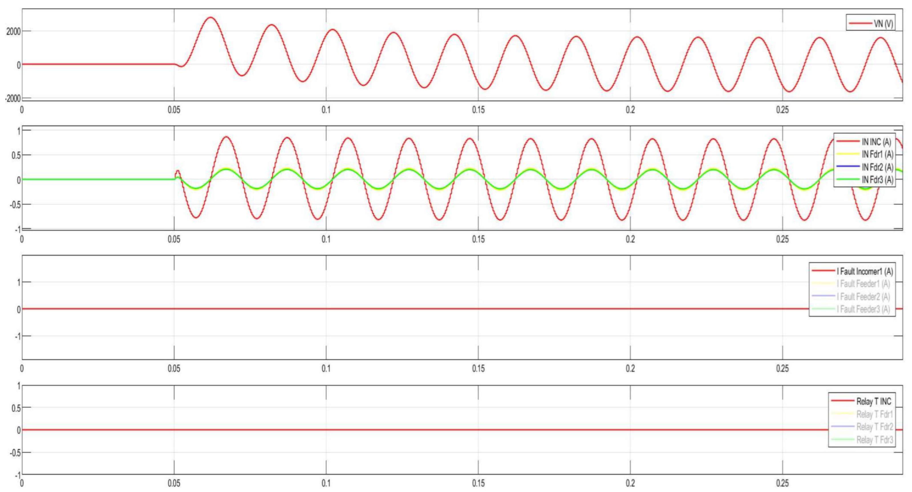
Disturbance record of SPGF with transient resistance of Rf = 5000 Ohm at the Feeder No.1, Substation No.1 in the 10 kV network with the isolated neutral configuration.
Figure 53.
Disturbance record of SPGF with transient resistance of Rf = 5000 Ohm at the Feeder No.1, Substation No.1 in the 10 kV network with the isolated neutral configuration.
Figure 54.
Single line diagram with SPGF with the transient resistance of Rf = 5000 Ohm on the Substation No.1 bus in the 10 kV network with the isolated neutral configuration.
Figure 54.
Single line diagram with SPGF with the transient resistance of Rf = 5000 Ohm on the Substation No.1 bus in the 10 kV network with the isolated neutral configuration.
Figure 55.
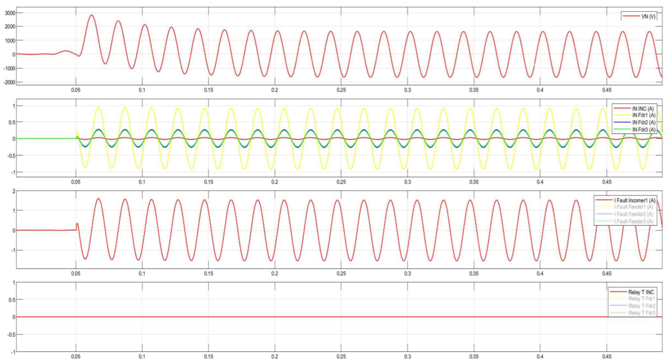
Disturbance record of SPGF with transient resistance of Rf = 5000 Ohm on the Substation No.1 bus in the 10 kV network with the isolated neutral configuration.
Figure 55.
Disturbance record of SPGF with transient resistance of Rf = 5000 Ohm on the Substation No.1 bus in the 10 kV network with the isolated neutral configuration.
Figure 56.
Single line diagram with SPGF with transient resistance of Rf = 5000 Ohm at the Feeder No.1, Substation No.2 in the 10 kV network with the isolated neutral configuration.
Figure 56.
Single line diagram with SPGF with transient resistance of Rf = 5000 Ohm at the Feeder No.1, Substation No.2 in the 10 kV network with the isolated neutral configuration.
Figure 57.
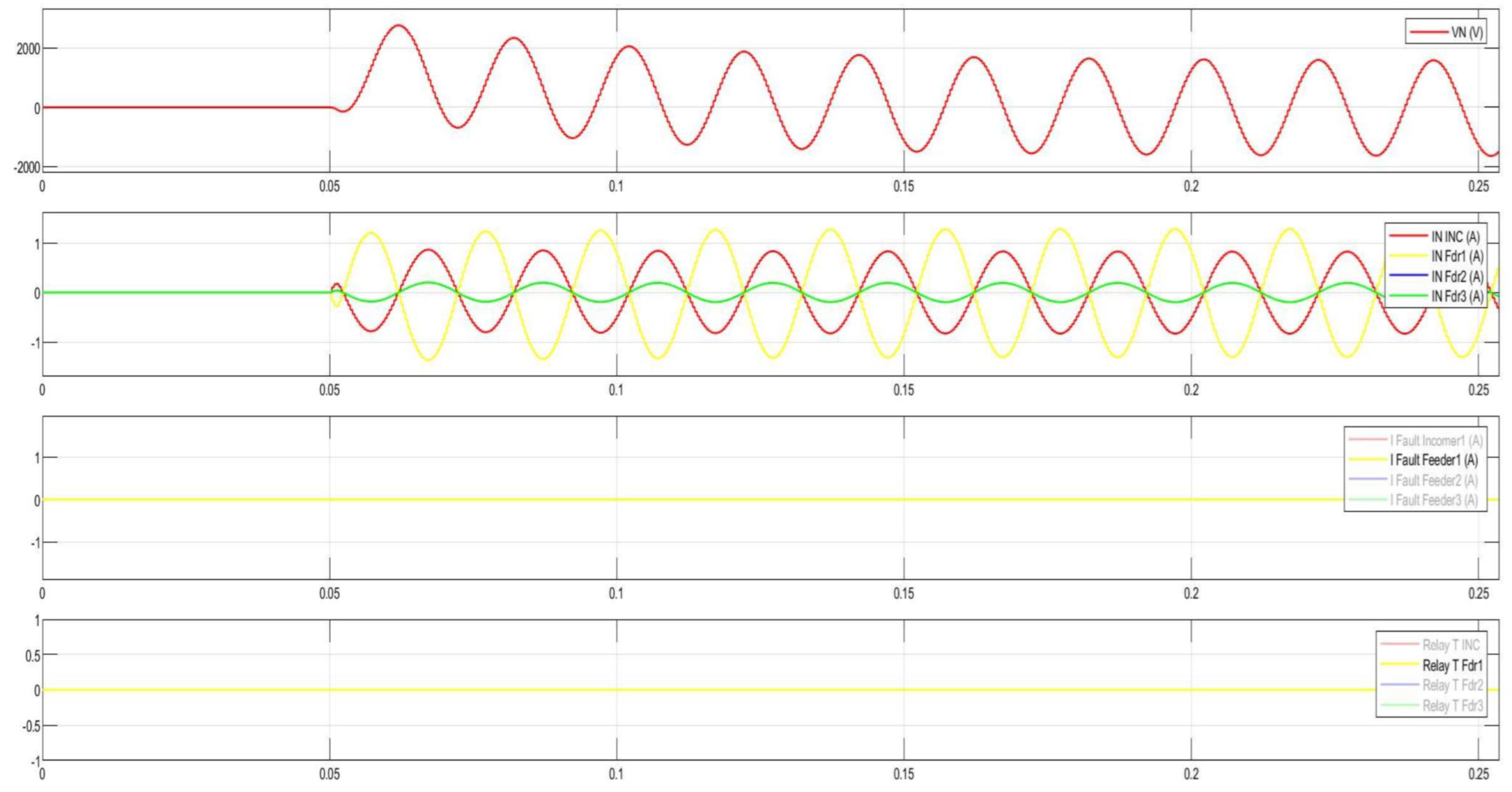
Disturbance record of SPGF with transient resistance of Rf = 5000 Ohm at the Feeder No.1, Substation No.2 in the 10 kV network with the isolated neutral configuration.
Figure 57.
Disturbance record of SPGF with transient resistance of Rf = 5000 Ohm at the Feeder No.1, Substation No.2 in the 10 kV network with the isolated neutral configuration.
Figure 58.
Single line diagram with SPGF with transient resistance of Rf = 5000 Ohm on the Substation No.2 bus in the 10 kV network with the isolated neutral configuration.
Figure 58.
Single line diagram with SPGF with transient resistance of Rf = 5000 Ohm on the Substation No.2 bus in the 10 kV network with the isolated neutral configuration.
Figure 59.
Disturbance record of SPGF with transient resistance of Rf = 5000 Ohm on the Substation No.2 bus in the 10 kV network with the isolated neutral configuration.
Figure 59.
Disturbance record of SPGF with transient resistance of Rf = 5000 Ohm on the Substation No.2 bus in the 10 kV network with the isolated neutral configuration.
Table 1.
Protection scheme comparison.
Table 1.
Protection scheme comparison.
| Scheme | Main Quantities | Principle | Data/Infrastructure |
|---|
| CGFPU | Zero sequence currents I0 per feeder | Zero sequence current angle and magnitude comparison ensures selectivity | Requires zero-sequence CT inputs from each feeder, copper cables to the CGFPU |
| Harmonic-based | Residual harmonic components (U0/I0) | Faulted feeder exhibits distinctive harmonic content (re-strikes, ASR detuning) | Fast Fourier Transform windowing, moderate sampling (1–5 kHz) |
| Directional Overcurrent | I0, U0 or negative sequence components | Directional torque (e.g., ∠U0 angle vs. ∠I0 angle + pickup | Local feeder relay, standard CT/VT; no communications required |
| Transient-based | HF content of U0/I0 | Uses first-cycle/high-freq signatures to point to faulted feeder | High sampling (≥20–100 kHz), low-latency digital signal processing; careful anti-aliasing |
Table 2.
Protection criteria.
Table 2.
Protection criteria.
| Criterion | CGFPU | Harmonic-Based | Directional Overcurrent | Transient Based |
|---|
| Sensitivity | High, zero sequence current angle and magnitude comparison keeps high sensitivity | Medium, it needs persistent arc, ASR detuning, weak for purely resistive SPGFs | Low, medium degrades for transient resistive SPGFs; there is a risk of pickup failure | Medium, high good if strong transients appear; can miss resistive faults |
| Speed | Fast, 20–40 ms; trips after validation | Medium, several cycles due to Fast Fourier Transform windows | Fast, 20–40 ms if pickup reached | Very fast, sub-cycle to 1 cycle |
| Selectivity | High, due to cross-feeder comparison | Medium, harmonics can spread system-wide | Medium, local decision; load unbalance can confuse | Medium, high but reflections/noise can confuse |
| Robustness, noise/CT/VT | High, as it uses power-frequency phasors and cross-checks | Medium, harmonic signal-to-noise ratio can be low | Medium, CT saturation, VT phase error impact | Medium, it is sensitive to noise, sampling, waveform distortion |
| Communications need | No | No | No | No |
Table 3.
Complexity and lifecycle cost.
Table 3.
Complexity and lifecycle cost.
| Criterion | CGFPU | Harmonic | Directional Overcurrent | Transient Based |
|---|
| Engineering effort | Low, centralized or distributed, cross-feeder angle/persistence settings | Medium, Fast Fourier Transform/phase locked loop setup, signal-to-noise ratio gating, persistence) | Low (per-feeder pickup/angle) | High, high-frequency digital signal processing tuning, possible time sync |
| Hardware | Medium, centralized unit and copper cables | Low standard relays, 2–5 kHz sampling, good VT residual | Low Standard relays | High, HF-capable relays/sensors; 20–100 kHz, low-latency path |
| Lifecycle cost | Low, medium, single centralized device for multiple feeders | Low, conventional protection relays | Low, mature and inexpensive | High, complex maintenance, calibration, and component cost |
Table 4.
Results of the analysis of the neutral displacement voltage, SPGF current errors, transient resistances at the admittance imbalance ΔY = 0%.
Table 4.
Results of the analysis of the neutral displacement voltage, SPGF current errors, transient resistances at the admittance imbalance ΔY = 0%.
| Rf ohm | ΔYpct | UN, V | UN sym, V | Err, Upct | If, A | If sym, A | Err, If pct |
|---|
| 1 | 0 | 5773.5 | 5773.5 | 0 | 4.86098 | 4.86098 | 0 |
| 100 | 0 | 5753.15 | 5753.15 | 0 | 4.84384 | 4.84384 | 0 |
| 500 | 0 | 5321.22 | 5321.22 | 0 | 4.48018 | 4.48018 | 0 |
| 1000 | 0 | 4416.56 | 4416.56 | 0 | 3.71851 | 3.71851 | 0 |
| 2000 | 0 | 2948.01 | 2948.01 | 0 | 2.48207 | 2.48207 | 0 |
| 3000 | 0 | 2125.27 | 2125.27 | 0 | 1.78937 | 1.78937 | 0 |
| 4000 | 0 | 1643.41 | 1643.41 | 0 | 1.38367 | 1.38367 | 0 |
| 5000 | 0 | 1334.33 | 1334.33 | 0 | 1.12344 | 1.12344 | 0 |
| 6000 | 0 | 1121.13 | 1121.13 | 0 | 0.94393 | 0.94393 | 0 |
| 7000 | 0 | 965.81 | 965.81 | 0 | 0.81316 | 0.81316 | 0 |
| 8000 | 0 | 847.87 | 847.87 | 0 | 0.71386 | 0.71386 | 0 |
| 9000 | 0 | 755.38 | 755.38 | 0 | 0.63599 | 0.63599 | 0 |
| 10,000 | 0 | 680.95 | 680.95 | 0 | 0.57332 | 0.57332 | 0 |
Table 5.
Results of the analysis of the neutral displacement voltage, SPGF current errors, and transient resistances at the admittance imbalance ΔY = 5%.
Table 5.
Results of the analysis of the neutral displacement voltage, SPGF current errors, and transient resistances at the admittance imbalance ΔY = 5%.
| Rf ohm | ΔYpct | UN, V | UN sym, V | Err, Upct | If, A | If sym, A | Err, If pct |
|---|
| 1 | 5 | 5773.64 | 5773.5 | 0 | 4.86301 | 4.86098 | 0.042 |
| 100 | 5 | 5767.13 | 5753.15 | 0.24 | 4.84586 | 4.84384 | 0.042 |
| 500 | 5 | 5385.88 | 5321.22 | 1.22 | 4.48205 | 4.48018 | 0.042 |
| 1000 | 5 | 4523.91 | 4416.56 | 2.43 | 3.72006 | 3.71851 | 0.042 |
| 2000 | 5 | 3091.31 | 2948.01 | 4.86 | 2.4831 | 2.48207 | 0.042 |
| 3000 | 5 | 2280.24 | 2125.27 | 7.29 | 1.79011 | 1.78937 | 0.042 |
| 4000 | 5 | 1803.19 | 1643.41 | 9.72 | 1.38424 | 1.38367 | 0.042 |
| 5000 | 5 | 1496.49 | 1334.33 | 12.15 | 1.12391 | 1.12344 | 0.042 |
| 6000 | 5 | 1284.63 | 1121.13 | 14.58 | 0.94433 | 0.94393 | 0.042 |
| 7000 | 5 | 1130.13 | 965.81 | 17.01 | 0.8135 | 0.81316 | 0.042 |
| 8000 | 5 | 1012.73 | 847.87 | 19.44 | 0.71416 | 0.71386 | 0.042 |
| 9000 | 5 | 920.61 | 755.38 | 21.87 | 0.63625 | 0.63599 | 0.042 |
| 10,000 | 5 | 846.45 | 680.95 | 24.3 | 0.57356 | 0.57332 | 0.042 |
Table 6.
Results of the analysis of the neutral displacement voltage, SPGF current errors, and transient resistances at the admittance imbalance ΔY = 10%.
Table 6.
Results of the analysis of the neutral displacement voltage, SPGF current errors, and transient resistances at the admittance imbalance ΔY = 10%.
| Rf ohm | ΔYpct | UN, V | UN sym, V | Err, Upct | If, A | If sym, A | Err, If pct |
|---|
| 1 | 10 | 5773.78 | 5773.5 | 0 | 4.86908 | 4.86098 | 0.167 |
| 100 | 10 | 5781.11 | 5753.15 | 0.49 | 4.85191 | 4.84384 | 0.167 |
| 500 | 10 | 5450.55 | 5321.22 | 2.43 | 4.48764 | 4.48018 | 0.167 |
| 1000 | 10 | 4631.25 | 4416.56 | 4.86 | 3.7247 | 3.71851 | 0.167 |
| 2000 | 10 | 3234.61 | 2948.01 | 9.72 | 2.4862 | 2.48207 | 0.167 |
| 3000 | 10 | 2435.2 | 2125.27 | 14.58 | 1.79235 | 1.78937 | 0.167 |
| 4000 | 10 | 1962.96 | 1643.41 | 19.44 | 1.38597 | 1.38367 | 0.167 |
| 5000 | 10 | 1658.64 | 1334.33 | 24.3 | 1.12531 | 1.12344 | 0.167 |
| 6000 | 10 | 1448.12 | 1121.13 | 29.17 | 0.94551 | 0.94393 | 0.167 |
| 7000 | 10 | 1294.45 | 965.81 | 34.03 | 0.81452 | 0.81316 | 0.167 |
| 8000 | 10 | 1177.59 | 847.87 | 38.89 | 0.71505 | 0.71386 | 0.167 |
| 9000 | 10 | 1085.84 | 755.38 | 43.75 | 0.63705 | 0.63599 | 0.167 |
| 10,000 | 10 | 1011.95 | 680.95 | 48.61 | 0.57428 | 0.57332 | 0.167 |
Table 7.
Results of the analysis of the neutral displacement voltage, SPGF current errors, and transient resistances at the admittance imbalance ΔY = 15%.
Table 7.
Results of the analysis of the neutral displacement voltage, SPGF current errors, and transient resistances at the admittance imbalance ΔY = 15%.
| Rf ohm | ΔYpct | UN, V | UN sym, V | Err, Upct | If, A | If sym, A | Err, If pct |
|---|
| 1 | 15 | 5773.92 | 5773.5 | 0.01 | 4.87918 | 4.86098 | 0.374 |
| 100 | 15 | 5795.1 | 5753.15 | 0.73 | 4.86197 | 4.84384 | 0.374 |
| 500 | 15 | 5515.21 | 5321.22 | 3.65 | 4.49695 | 4.48018 | 0.374 |
| 1000 | 15 | 4738.59 | 4416.56 | 7.29 | 3.73243 | 3.71851 | 0.374 |
| 2000 | 15 | 3377.91 | 2948.01 | 14.58 | 2.49136 | 2.48207 | 0.374 |
| 3000 | 15 | 2590.17 | 2125.27 | 21.87 | 1.79607 | 1.78937 | 0.374 |
| 4000 | 15 | 2122.73 | 1643.41 | 29.17 | 1.38885 | 1.38367 | 0.374 |
| 5000 | 15 | 1820.8 | 1334.33 | 36.46 | 1.12764 | 1.12344 | 0.374 |
| 6000 | 15 | 1611.61 | 1121.13 | 43.75 | 0.94747 | 0.94393 | 0.374 |
| 7000 | 15 | 1458.77 | 965.81 | 51.04 | 0.81621 | 0.81316 | 0.374 |
| 8000 | 15 | 1342.45 | 847.87 | 58.33 | 0.71654 | 0.71386 | 0.374 |
| 9000 | 15 | 1251.08 | 755.38 | 65.62 | 0.63837 | 0.63599 | 0.374 |
| 10,000 | 15 | 1177.46 | 680.95 | 72.91 | 0.57547 | 0.57332 | 0.374 |
Table 8.
Fault current, If, A and transient resistance, Rf.
Table 8.
Fault current, If, A and transient resistance, Rf.
| C0Σ (µF) | 1 | 100 | 500 | 1000 | 2000 | 3000 | 4000 | 5000 | 6000 | 7000 | 8000 | 9000 | 10,000 |
|---|
| 1 | 5.441 | 5.417 | 4.922 | 3.960 | 2.550 | 1.814 | 1.395 | 1.130 | 0.948 | 0.815 | 0.715 | 0.637 | 0.574 |
| 2 | 10.883 | 10.694 | 7.920 | 5.100 | 2.790 | 1.895 | 1.431 | 1.148 | 0.959 | 0.822 | 0.720 | 0.640 | 0.577 |
| 3 | 16.324 | 15.708 | 9.427 | 5.443 | 2.843 | 1.911 | 1.438 | 1.152 | 0.961 | 0.824 | 0.721 | 0.641 | 0.577 |
| 4 | 21.765 | 20.366 | 10.200 | 5.581 | 2.862 | 1.917 | 1.440 | 1.153 | 0.961 | 0.824 | 0.721 | 0.641 | 0.577 |
| 5 | 27.207 | 24.611 | 10.629 | 5.648 | 2.871 | 1.920 | 1.441 | 1.154 | 0.962 | 0.824 | 0.721 | 0.641 | 0.577 |
| 6 | 32.648 | 28.419 | 10.886 | 5.685 | 2.876 | 1.921 | 1.442 | 1.154 | 0.962 | 0.825 | 0.722 | 0.641 | 0.577 |
| 7 | 38.089 | 31.794 | 11.050 | 5.708 | 2.878 | 1.922 | 1.442 | 1.154 | 0.962 | 0.825 | 0.722 | 0.641 | 0.577 |
| 8 | 43.530 | 34.758 | 11.161 | 5.723 | 2.880 | 1.923 | 1.443 | 1.154 | 0.962 | 0.825 | 0.722 | 0.641 | 0.577 |
| 10 | 54.412 | 39.599 | 11.295 | 5.741 | 2.883 | 1.923 | 1.443 | 1.154 | 0.962 | 0.825 | 0.722 | 0.641 | 0.577 |
Table 9.
Ground overcurrent settings for various transient resistances.
Table 9.
Ground overcurrent settings for various transient resistances.
| C0Σ (µF) | 1 | 100 | 500 | 1000 | 2000 | 3000 | 4000 | 5000 | 6000 | 7000 | 8000 | 9000 | 10,000 |
|---|
| 1 | 3.63 | 3.61 | 3.28 | 2.64 | 1.70 | 1.21 | 0.93 | 0.75 | 0.63 | 0.54 | 0.48 | 0.42 | 0.38 |
| 2 | 7.26 | 7.13 | 5.28 | 3.40 | 1.86 | 1.26 | 0.95 | 0.77 | 0.64 | 0.55 | 0.48 | 0.43 | 0.38 |
| 3 | 10.88 | 10.47 | 6.28 | 3.63 | 1.90 | 1.27 | 0.96 | 0.77 | 0.64 | 0.55 | 0.48 | 0.43 | 0.38 |
| 4 | 14.51 | 13.58 | 6.80 | 3.72 | 1.91 | 1.28 | 0.96 | 0.77 | 0.64 | 0.55 | 0.48 | 0.43 | 0.38 |
| 5 | 18.14 | 16.41 | 7.09 | 3.77 | 1.91 | 1.28 | 0.96 | 0.77 | 0.64 | 0.55 | 0.48 | 0.43 | 0.38 |
| 6 | 21.77 | 18.95 | 7.26 | 3.79 | 1.92 | 1.28 | 0.96 | 0.77 | 0.64 | 0.55 | 0.48 | 0.43 | 0.38 |
| 7 | 25.39 | 21.20 | 7.37 | 3.81 | 1.92 | 1.28 | 0.96 | 0.77 | 0.64 | 0.55 | 0.48 | 0.43 | 0.38 |
| 8 | 29.02 | 23.17 | 7.44 | 3.82 | 1.92 | 1.28 | 0.96 | 0.77 | 0.64 | 0.55 | 0.48 | 0.43 | 0.38 |
| 10 | 36.27 | 26.40 | 7.53 | 3.83 | 1.92 | 1.28 | 0.96 | 0.77 | 0.64 | 0.55 | 0.48 | 0.43 | 0.38 |
Table 10.
Loop integrity coefficient, β and transient resistance, Rf.
Table 10.
Loop integrity coefficient, β and transient resistance, Rf.
| C0Σ | 1 | 100 | 500 | 1000 | 2000 | 3000 | 4000 | 5000 | 6000 | 7000 | 8000 | 9000 | 10,000 |
|---|
| 1 | 1.000 | 0.996 | 0.905 | 0.728 | 0.469 | 0.333 | 0.256 | 0.208 | 0.174 | 0.150 | 0.131 | 0.117 | 0.106 |
| 2 | 1.000 | 0.983 | 0.728 | 0.469 | 0.256 | 0.174 | 0.131 | 0.106 | 0.088 | 0.076 | 0.066 | 0.059 | 0.053 |
| 3 | 1.000 | 0.962 | 0.577 | 0.333 | 0.174 | 0.117 | 0.088 | 0.071 | 0.059 | 0.050 | 0.044 | 0.039 | 0.035 |
| 4 | 1.000 | 0.936 | 0.469 | 0.256 | 0.131 | 0.088 | 0.066 | 0.053 | 0.044 | 0.038 | 0.033 | 0.029 | 0.027 |
| 5 | 1.000 | 0.905 | 0.391 | 0.208 | 0.106 | 0.071 | 0.053 | 0.042 | 0.035 | 0.030 | 0.027 | 0.024 | 0.021 |
| 6 | 1.000 | 0.870 | 0.333 | 0.174 | 0.088 | 0.059 | 0.044 | 0.035 | 0.029 | 0.025 | 0.022 | 0.020 | 0.018 |
| 7 | 1.000 | 0.835 | 0.290 | 0.150 | 0.076 | 0.050 | 0.038 | 0.030 | 0.025 | 0.022 | 0.019 | 0.017 | 0.015 |
| 8 | 1.000 | 0.798 | 0.256 | 0.131 | 0.066 | 0.044 | 0.033 | 0.027 | 0.022 | 0.019 | 0.017 | 0.015 | 0.013 |
| 10 | 1.000 | 0.728 | 0.208 | 0.106 | 0.053 | 0.035 | 0.027 | 0.021 | 0.018 | 0.015 | 0.013 | 0.012 | 0.011 |
Table 11.
Parameters.
| Frequency, f (Hz) | 50 | | | | | | |
| Line voltage ULL, (V) | 10,000 | | | | | | |
| Phase voltage, Uph (V) | 5773 | | | | | | |
| ASR L(H) | 1.26 | | | | | | |
| ASR tuning ratio | 0.9, 1.0, 1.1 | | | | | |
| Resistor RN (Ohm) | 100, 500, 1000 | | | | |
| Transient resistance Rf (Ohm) | 1, 100, 500, 1000, 2000, 3000, 4000, 5000, 6000, 7000, 8000, 9000, 10,000 |
| Capacitance C0 (µF) | 1, 2, 3, 4, 5, 6, 7, 8, 10 | | | | |
Table 12.
SPGF current, If, A, and transient resistance, Rf for isolated neutral.
Table 12.
SPGF current, If, A, and transient resistance, Rf for isolated neutral.
| C0Σ (µF) | 1 | 100 | 500 | 1000 | 2000 | 3000 | 4000 | 5000 | 6000 | 7000 | 8000 | 9000 | 10,000 |
|---|
| 1 | 5.441 | 5.417 | 4.922 | 3.960 | 2.550 | 1.814 | 1.395 | 1.130 | 0.948 | 0.815 | 0.715 | 0.637 | 0.574 |
| 2 | 10.883 | 10.694 | 7.920 | 5.100 | 2.790 | 1.895 | 1.431 | 1.148 | 0.959 | 0.822 | 0.720 | 0.640 | 0.577 |
| 3 | 16.324 | 15.708 | 9.427 | 5.443 | 2.843 | 1.911 | 1.438 | 1.152 | 0.961 | 0.824 | 0.721 | 0.641 | 0.577 |
| 4 | 21.765 | 20.366 | 10.200 | 5.581 | 2.862 | 1.917 | 1.440 | 1.153 | 0.961 | 0.824 | 0.721 | 0.641 | 0.577 |
| 5 | 27.207 | 24.611 | 10.629 | 5.648 | 2.871 | 1.920 | 1.441 | 1.154 | 0.962 | 0.824 | 0.721 | 0.641 | 0.577 |
| 6 | 32.648 | 28.419 | 10.886 | 5.685 | 2.876 | 1.921 | 1.442 | 1.154 | 0.962 | 0.825 | 0.722 | 0.641 | 0.577 |
| 7 | 38.089 | 31.794 | 11.050 | 5.708 | 2.878 | 1.922 | 1.442 | 1.154 | 0.962 | 0.825 | 0.722 | 0.641 | 0.577 |
| 8 | 43.530 | 34.758 | 11.161 | 5.723 | 2.880 | 1.923 | 1.443 | 1.154 | 0.962 | 0.825 | 0.722 | 0.641 | 0.577 |
| 9 | 48.971 | 37.178 | 11.228 | 5.732 | 2.8815 | 1.923 | 1.443 | 1.154 | 0.962 | 0.825 | 0.722 | 0.641 | 0.577 |
| 10 | 54.412 | 39.599 | 11.295 | 5.741 | 2.883 | 1.923 | 1.443 | 1.154 | 0.962 | 0.825 | 0.722 | 0.641 | 0.577 |
Table 13.
SPGF current, If, A, and transient resistance, Rf for compensated neutral, 0.9 ASR under compensation tuning.
Table 13.
SPGF current, If, A, and transient resistance, Rf for compensated neutral, 0.9 ASR under compensation tuning.
| C0Σ (µF) | 1 | 100 | 500 | 1000 | 2000 | 3000 | 4000 | 5000 | 6000 | 7000 | 8000 | 9000 | 10,000 |
|---|
| 1 | 0.59 | 0.59 | 0.58 | 0.57 | 0.54 | 0.52 | 0.49 | 0.46 | 0.44 | 0.42 | 0.39 | 0.37 | 0.36 |
| 2 | 1.42 | 1.40 | 1.32 | 1.23 | 1.06 | 0.92 | 0.81 | 0.72 | 0.64 | 0.58 | 0.53 | 0.49 | 0.45 |
| 3 | 2.62 | 2.54 | 2.24 | 1.93 | 1.49 | 1.20 | 1.00 | 0.86 | 0.75 | 0.66 | 0.60 | 0.54 | 0.50 |
| 4 | 4.22 | 4.00 | 3.25 | 2.59 | 1.82 | 1.39 | 1.13 | 0.95 | 0.81 | 0.71 | 0.64 | 0.57 | 0.52 |
| 5 | 6.23 | 5.74 | 4.25 | 3.16 | 2.07 | 1.53 | 1.21 | 1.00 | 0.85 | 0.74 | 0.66 | 0.59 | 0.54 |
| 6 | 8.64 | 7.69 | 5.19 | 3.63 | 2.25 | 1.62 | 1.27 | 1.04 | 0.88 | 0.76 | 0.68 | 0.60 | 0.55 |
| 7 | 11.42 | 9.80 | 6.03 | 4.00 | 2.38 | 1.69 | 1.31 | 1.07 | 0.90 | 0.78 | 0.69 | 0.61 | 0.55 |
| 8 | 14.55 | 12.00 | 6.76 | 4.30 | 2.47 | 1.73 | 1.33 | 1.08 | 0.91 | 0.79 | 0.69 | 0.62 | 0.56 |
| 9 | 18.15 | 14.24 | 7.33 | 4.51 | 2.53 | 1.76 | 1.35 | 1.09 | 0.92 | 0.79 | 0.69 | 0.62 | 0.56 |
| 10 | 21.76 | 16.49 | 7.91 | 4.72 | 2.60 | 1.79 | 1.37 | 1.11 | 0.93 | 0.80 | 0.70 | 0.63 | 0.57 |
Table 14.
SPGF current, If, A, and transient resistance, Rf for compensated neutral, 1.0 ASR tuning.
Table 14.
SPGF current, If, A, and transient resistance, Rf for compensated neutral, 1.0 ASR tuning.
| C0Σ (µF) | 1 | 100 | 500 | 1000 | 2000 | 3000 | 4000 | 5000 | 6000 | 7000 | 8000 | 9000 | 10,000 |
|---|
| 1 | 0.26 | 0.26 | 0.25 | 0.25 | 0.24 | 0.23 | 0.22 | 0.21 | 0.20 | 0.20 | 0.19 | 0.18 | 0.18 |
| 2 | 1.02 | 1.00 | 0.94 | 0.87 | 0.75 | 0.67 | 0.60 | 0.54 | 0.50 | 0.46 | 0.42 | 0.39 | 0.37 |
| 3 | 2.28 | 2.20 | 1.91 | 1.64 | 1.28 | 1.05 | 0.89 | 0.77 | 0.68 | 0.61 | 0.55 | 0.50 | 0.46 |
| 4 | 4.03 | 3.77 | 3.00 | 2.38 | 1.69 | 1.31 | 1.07 | 0.90 | 0.78 | 0.69 | 0.61 | 0.55 | 0.51 |
| 5 | 6.23 | 5.64 | 4.08 | 3.02 | 1.99 | 1.48 | 1.18 | 0.98 | 0.84 | 0.73 | 0.65 | 0.58 | 0.53 |
| 6 | 8.87 | 7.73 | 5.07 | 3.53 | 2.19 | 1.59 | 1.25 | 1.03 | 0.87 | 0.76 | 0.67 | 0.60 | 0.54 |
| 7 | 11.91 | 9.96 | 5.94 | 3.93 | 2.34 | 1.67 | 1.29 | 1.06 | 0.89 | 0.77 | 0.68 | 0.61 | 0.55 |
| 8 | 15.32 | 12.26 | 6.70 | 4.25 | 2.45 | 1.72 | 1.33 | 1.08 | 0.91 | 0.79 | 0.69 | 0.62 | 0.56 |
| 9 | 19.22 | 14.57 | 7.29 | 4.47 | 2.52 | 1.76 | 1.35 | 1.09 | 0.92 | 0.80 | 0.70 | 0.63 | 0.56 |
| 10 | 23.11 | 16.88 | 7.88 | 4.69 | 2.59 | 1.79 | 1.37 | 1.10 | 0.93 | 0.80 | 0.70 | 0.63 | 0.56 |
Table 15.
SPGF current, If, A, and transient resistance, Rf for compensated neutral, 1.1 overcompensated ASR tuning.
Table 15.
SPGF current, If, A, and transient resistance, Rf for compensated neutral, 1.1 overcompensated ASR tuning.
| C0Σ (µF) | 1 | 100 | 500 | 1000 | 2000 | 3000 | 4000 | 5000 | 6000 | 7000 | 8000 | 9000 | 10,000 |
|---|
| 1 | 0.61 | 0.61 | 0.60 | 0.58 | 0.55 | 0.51 | 0.48 | 0.45 | 0.43 | 0.40 | 0.38 | 0.36 | 0.34 |
| 2 | 1.56 | 1.53 | 1.41 | 1.27 | 1.07 | 0.91 | 0.79 | 0.70 | 0.63 | 0.57 | 0.52 | 0.48 | 0.44 |
| 3 | 2.98 | 2.85 | 2.40 | 2.01 | 1.50 | 1.19 | 0.99 | 0.85 | 0.74 | 0.66 | 0.59 | 0.53 | 0.49 |
| 4 | 4.90 | 4.53 | 3.46 | 2.67 | 1.83 | 1.39 | 1.12 | 0.94 | 0.81 | 0.71 | 0.63 | 0.57 | 0.52 |
| 5 | 7.31 | 6.50 | 4.49 | 3.23 | 2.07 | 1.53 | 1.21 | 1.00 | 0.85 | 0.74 | 0.66 | 0.59 | 0.54 |
| 6 | 10.17 | 8.66 | 5.41 | 3.68 | 2.25 | 1.62 | 1.26 | 1.04 | 0.88 | 0.76 | 0.67 | 0.60 | 0.55 |
| 7 | 13.45 | 10.93 | 6.22 | 4.04 | 2.38 | 1.68 | 1.30 | 1.06 | 0.90 | 0.78 | 0.69 | 0.61 | 0.55 |
| 8 | 17.10 | 13.25 | 6.92 | 4.33 | 2.47 | 1.73 | 1.33 | 1.08 | 0.91 | 0.79 | 0.69 | 0.62 | 0.56 |
| 9 | 21.25 | 15.55 | 7.47 | 4.53 | 2.53 | 1.76 | 1.35 | 1.09 | 0.92 | 0.79 | 0.69 | 0.62 | 0.56 |
| 10 | 25.40 | 17.85 | 8.02 | 4.74 | 2.60 | 1.79 | 1.37 | 1.11 | 0.93 | 0.80 | 0.70 | 0.63 | 0.57 |
Table 16.
SPGF current, If, A, and transient resistance, Rf for resistively grounded neutral, NGR RN = 100 Ohm.
Table 16.
SPGF current, If, A, and transient resistance, Rf for resistively grounded neutral, NGR RN = 100 Ohm.
| C0Σ (µF) | 1 | 100 | 500 | 1000 | 2000 | 3000 | 4000 | 5000 | 6000 | 7000 | 8000 | 9000 | 10,000 |
|---|
| 1 | 57.42 | 28.96 | 9.64 | 5.25 | 2.75 | 1.86 | 1.41 | 1.13 | 0.95 | 0.81 | 0.71 | 0.63 | 0.57 |
| 2 | 58.17 | 29.25 | 9.67 | 5.26 | 2.75 | 1.86 | 1.41 | 1.13 | 0.95 | 0.81 | 0.71 | 0.63 | 0.57 |
| 3 | 59.40 | 29.70 | 9.73 | 5.28 | 2.76 | 1.87 | 1.41 | 1.13 | 0.95 | 0.81 | 0.71 | 0.63 | 0.57 |
| 4 | 61.09 | 30.32 | 9.81 | 5.31 | 2.77 | 1.87 | 1.41 | 1.13 | 0.95 | 0.81 | 0.71 | 0.64 | 0.57 |
| 5 | 63.19 | 31.06 | 9.90 | 5.33 | 2.77 | 1.87 | 1.41 | 1.14 | 0.95 | 0.82 | 0.71 | 0.64 | 0.57 |
| 6 | 65.67 | 31.91 | 10.00 | 5.36 | 2.78 | 1.88 | 1.42 | 1.14 | 0.95 | 0.82 | 0.71 | 0.64 | 0.57 |
| 7 | 68.48 | 32.84 | 10.10 | 5.39 | 2.79 | 1.88 | 1.42 | 1.14 | 0.95 | 0.82 | 0.72 | 0.64 | 0.57 |
| 8 | 71.59 | 33.83 | 10.20 | 5.42 | 2.80 | 1.88 | 1.42 | 1.14 | 0.95 | 0.82 | 0.72 | 0.64 | 0.57 |
| 9 | 75.07 | 34.85 | 10.3 | 5.45 | 2.80 | 1.88 | 1.42 | 1.14 | 0.95 | 0.82 | 0.72 | 0.64 | 0.57 |
| 10 | 78.55 | 35.88 | 10.40 | 5.48 | 2.81 | 1.89 | 1.42 | 1.14 | 0.95 | 0.82 | 0.72 | 0.64 | 0.57 |
Table 17.
SPGF current, If, A, and transient resistance, Rf for resistively grounded neutral, NGR RN = 500 Ohm.
Table 17.
SPGF current, If, A, and transient resistance, Rf for resistively grounded neutral, NGR RN = 500 Ohm.
| C0Σ (µF) | 1 | 100 | 500 | 1000 | 2000 | 3000 | 4000 | 5000 | 6000 | 7000 | 8000 | 9000 | 10,000 |
|---|
| 1 | 12.74 | 10.60 | 6.21 | 4.06 | 2.39 | 1.69 | 1.31 | 1.07 | 0.90 | 0.78 | 0.69 | 0.61 | 0.55 |
| 2 | 15.84 | 13.06 | 7.18 | 4.48 | 2.53 | 1.76 | 1.35 | 1.10 | 0.92 | 0.79 | 0.70 | 0.62 | 0.56 |
| 3 | 19.96 | 16.22 | 8.16 | 4.85 | 2.65 | 1.82 | 1.38 | 1.12 | 0.94 | 0.81 | 0.71 | 0.63 | 0.57 |
| 4 | 24.59 | 19.59 | 8.97 | 5.11 | 2.72 | 1.85 | 1.40 | 1.13 | 0.94 | 0.81 | 0.71 | 0.63 | 0.57 |
| 5 | 29.50 | 22.93 | 9.56 | 5.29 | 2.77 | 1.87 | 1.41 | 1.14 | 0.95 | 0.82 | 0.71 | 0.64 | 0.57 |
| 6 | 34.56 | 26.11 | 10.00 | 5.41 | 2.80 | 1.89 | 1.42 | 1.14 | 0.95 | 0.82 | 0.72 | 0.64 | 0.57 |
| 7 | 39.72 | 29.07 | 10.32 | 5.49 | 2.82 | 1.90 | 1.43 | 1.14 | 0.96 | 0.82 | 0.72 | 0.64 | 0.57 |
| 8 | 44.95 | 31.78 | 10.55 | 5.55 | 2.83 | 1.90 | 1.43 | 1.15 | 0.96 | 0.82 | 0.72 | 0.64 | 0.58 |
| 9 | 50.23 | 34.12 | 10.71 | 5.58 | 2.84 | 1.90 | 1.43 | 1.15 | 0.96 | 0.82 | 0.72 | 0.64 | 0.58 |
| 10 | 55.51 | 36.46 | 10.87 | 5.62 | 2.85 | 1.91 | 1.44 | 1.15 | 0.96 | 0.82 | 0.72 | 0.64 | 0.58 |
Table 18.
SPGF current, If, A, and transient resistance, Rf for resistively grounded neutral, NGR RN = 1000 Ohm.
Table 18.
SPGF current, If, A, and transient resistance, Rf for resistively grounded neutral, NGR RN = 1000 Ohm.
| C0Σ (µF) | 1 | 100 | 500 | 1000 | 2000 | 3000 | 4000 | 5000 | 6000 | 7000 | 8000 | 9000 | 10,000 |
|---|
| 1 | 7.93 | 7.19 | 5.05 | 3.59 | 2.24 | 1.62 | 1.27 | 1.04 | 0.88 | 0.77 | 0.68 | 0.61 | 0.55 |
| 2 | 12.31 | 11.04 | 6.95 | 4.48 | 2.56 | 1.78 | 1.36 | 1.10 | 0.93 | 0.80 | 0.70 | 0.63 | 0.56 |
| 3 | 17.30 | 15.25 | 8.40 | 5.00 | 2.70 | 1.85 | 1.40 | 1.13 | 0.94 | 0.81 | 0.71 | 0.63 | 0.57 |
| 4 | 22.50 | 19.37 | 9.35 | 5.28 | 2.77 | 1.88 | 1.42 | 1.14 | 0.95 | 0.82 | 0.72 | 0.64 | 0.57 |
| 5 | 27.78 | 23.24 | 9.96 | 5.43 | 2.81 | 1.89 | 1.43 | 1.14 | 0.95 | 0.82 | 0.72 | 0.64 | 0.57 |
| 6 | 33.12 | 26.81 | 10.36 | 5.53 | 2.83 | 1.90 | 1.43 | 1.15 | 0.96 | 0.82 | 0.72 | 0.64 | 0.58 |
| 7 | 38.49 | 30.03 | 10.63 | 5.59 | 2.85 | 1.91 | 1.43 | 1.15 | 0.96 | 0.82 | 0.72 | 0.64 | 0.58 |
| 8 | 43.87 | 32.93 | 10.82 | 5.63 | 2.86 | 1.91 | 1.44 | 1.15 | 0.96 | 0.82 | 0.72 | 0.64 | 0.58 |
| 9 | 49.26 | 35.35 | 10.94 | 5.65 | 2.86 | 1.91 | 1.44 | 1.15 | 0.96 | 0.82 | 0.72 | 0.64 | 0.58 |
| 10 | 54.66 | 37.78 | 11.06 | 5.68 | 2.87 | 1.92 | 1.44 | 1.15 | 0.96 | 0.82 | 0.72 | 0.64 | 0.58 |
Table 19.
SPGF current values at the Feeder No.1, Substation No.1 for different transient resistances and capacitive currents in the 10 kV network with the isolated neutral configuration.
Table 19.
SPGF current values at the Feeder No.1, Substation No.1 for different transient resistances and capacitive currents in the 10 kV network with the isolated neutral configuration.
| No. | Resistance Rf, Ohm | Cumulative Current, A | Ground Fault Current at Feeder No.1, Substation No.1, A | Capacitive Current at Feeder No.2,
Substation No.1, A | Capacitive Current at Feeder No.3,
Substation No.1, A | Capacitive Current at Feeder No.1,
Substation No.2, A | Capacitive Current at Feeder No.2,
Substation No.2, A | Capacitive Current at Feeder No.3,
Substation No.2, A |
|---|
| 1 | 1 | 15.82∠−129.02° | 6.37∠−129.02° | 2.69∠50.98° | 2.47∠50.98° | 2.25∠50.98° | 2.02∠50.98° | 2.02∠50.98° |
| 2 | 100 | 15.17∠−145.16° | 6.10∠−145.16° | 2.58∠34.84° | 2.37∠34.84° | 2.15∠34.84° | 1.94∠34.84° | 1.94∠34.84° |
| 3 | 500 | 8.91∠175.59° | 3.59∠175.59° | 1.52∠−4.41° | 1.39∠−4.41° | 1.27∠−4.40° | 1.14∠−4.40° | 1.14∠−4.40° |
| 4 | 1000 | 5.11∠160.15° | 2.06∠160.15° | 0.87∠−19.85° | 0.80∠−19.85° | 0.73∠−19.84° | 0.65∠−19.84° | 0.65∠−19.84° |
| 5 | 3000 | 1.79∠147.83° | 0.72∠147.78° | 0.31∠−32.21° | 0.28∠−32.21° | 0.25∠−32.17° | 0.23∠−32.17° | 0.23∠−32.17° |
| 6 | 5000 | 1.08∠145.18° | 0.43∠145.18° | 0.19∠−34.81° | 0.17∠−34.81° | 0.15∠−34.75° | 0.14∠−34.74° | 0.14∠−34.73° |
| 7 | 10,000 | 0.54∠143.35° | 0.22∠143.18° | 0.09∠−36.79° | 0.09∠−36.79° | 0.08∠−36.67° | 0.07∠−36.65° | 0.07∠−36.64° |
Table 20.
Dependence of the Loop integrity coefficient, sensitivity ratio, zero-sequence voltage and current angle difference from transient resistances during SPGF at the Feeder No.1, Substation No.1.
Table 20.
Dependence of the Loop integrity coefficient, sensitivity ratio, zero-sequence voltage and current angle difference from transient resistances during SPGF at the Feeder No.1, Substation No.1.
| No. | Resistance Rf, Ohm | Loop Integrity Coefficient, β | Sensitivity Ratio | Zero-Sequence Voltage, kV | Current Angle Difference, Deg |
|---|
| 1 | 1 | 1.000 | 1.5 | 5.770 | 180.00° |
| 2 | 100 | 0.959 | 1.5 | 5.533 | 180.00° |
| 3 | 500 | 0.563 | 1.5 | 3.250 | 180.00° |
| 4 | 1000 | 0.323 | 1.5 | 1.864 | 180.00° |
| 5 | 3000 | 0.113 | 1.5 | 0.653 | 179.99° |
| 6 | 5000 | 0.068 | 1.5 | 0.394 | 179.99° |
| 7 | 10,000 | 0.034 | 1.5 | 0.197 | 179.97° |
Table 21.
SPGF current values with different transient resistances on the Substation No.1 bus and capacitive currents in the 10 kV network with the isolated neutral configuration.
Table 21.
SPGF current values with different transient resistances on the Substation No.1 bus and capacitive currents in the 10 kV network with the isolated neutral configuration.
| No. | Resistance Rf, Ohm | Cumulative Current, A | Capacitive Current at the Feeder No.1, Substation
No.1, A | Capacitive Current at the Feeder No.2, Substation
No.1, A | Capacitive Current at the Feeder No.3, Substation
No.1, A | Capacitive Current at the Feeder No.1, Substation
No.2, A | Capacitive Current at the Feeder No.2, Substation
No.2, A | Capacitive Current at the Feeder No.3, Substation
No.2, A |
|---|
| 1 | 1 | 16.01∠−127.61° | 9.57∠52.39° | 2.73∠52.39° | 2.50∠52.39° | 2.27∠52.39° | 2.27∠52.39° | 2.27∠52.39° |
| 2 | 100 | 15.35∠−143.75° | 9.17∠36.25° | 2.62∠36.25° | 2.40∠36.25° | 2.18∠36.25° | 1.96∠36.25° | 1.96∠36.25° |
| 3 | 500 | 9.02∠−177.01° | 5.39∠−2.99° | 1.54∠−3.00° | 1.41∠−3.00° | 1.28∠−2.99° | 1.15∠−2.99° | 1.15∠−2.99° |
| 4 | 1000 | 5.17∠167.57° | 3.09∠−18.43° | 0.88∠−18.44° | 0.81∠−18.44° | 0.73∠−18.43° | 0.66∠−18.43° | 0.66∠−18.43° |
| 5 | 3000 | 1.81∠149.24° | 1.08∠−30.77° | 0.31∠−30.81° | 0.28∠−30.81° | 0.26∠−30.77° | 0.23∠−30.76° | 0.23∠−30.76° |
| 6 | 5000 | 1.09∠146.67° | 0.65∠−33.34° | 0.19∠−33.41° | 0.17∠−33.41° | 0.16∠−33.35° | 0.14∠−33.34° | 0.14∠−33.33° |
| 7 | 10,000 | 0.55∠144.77° | 0.33∠−35.26° | 0.09∠−35.41° | 0.09∠−35.40° | 0.08∠−35.28° | 0.07∠−35.25° | 0.07∠−35.24° |
Table 22.
Dependence of circuit completeness, sensitivity ratio, zero-sequence voltage and current angle difference from transient resistance during single phase ground fault on the Substation No.1 bus.
Table 22.
Dependence of circuit completeness, sensitivity ratio, zero-sequence voltage and current angle difference from transient resistance during single phase ground fault on the Substation No.1 bus.
| No. | Resistance Rf, Ohm | Loop Integrity Coefficient, β | Sensitivity Ratio | Zero-Sequence Voltage, kV | Current Angle Difference, Deg |
|---|
| 1 | 1 | 1.000 | 1.5 | 5.770 | 180.00 |
| 2 | 100 | 0.959 | 1.5 | 5.533 | 180.00 |
| 3 | 500 | 0.563 | 1.5 | 3.250 | 180.00 |
| 4 | 1000 | 0.323 | 1.5 | 1.864 | 180.00 |
| 5 | 3000 | 0.113 | 1.5 | 0.653 | 179.99 |
| 6 | 5000 | 0.068 | 1.5 | 0.394 | 179.99 |
| 7 | 10,000 | 0.034 | 1.5 | 0.197 | 179.97 |
Table 23.
SPGF current values with different transient resistances at the Feeder No.1, substation No.2, and capacitive currents in the 10 kV network with the isolated neutral configuration.
Table 23.
SPGF current values with different transient resistances at the Feeder No.1, substation No.2, and capacitive currents in the 10 kV network with the isolated neutral configuration.
| No. | Resistance Rf, Ohm | Cumulative Current, A | Capacitive Current at the Feeder No.1, Substation No.1, A | Capacitive Current at the Feeder Eder No.2,
Substation No.1, A | Capacitive Current at the Feeder No.3, Substation No.1, A | Ground Fault Current at the Feeder No.1, Substation No.2, A | Capacitive Current at the Feeder No.2, Substation No.2, A | Capacitive Current at the Feeder No.3, Substation No.2, A |
|---|
| 1 | 1 | 15.72∠−130.00° | 6.33∠−130.00° | 2.68∠50.00° | 2.45∠50.00° | 13.49∠−130.00° | 2.01∠50.00° | 2.01∠50.00° |
| 2 | 100 | 15.07∠−145.15° | 6.07∠−145.15° | 2.57∠33.85° | 2.35∠33.85° | 12.93∠−145.15° | 1.93∠33.85° | 1.93∠33.85° |
| 3 | 500 | 8.85∠−174.60° | 3.56∠−174.60° | 1.51∠−5.40° | 1.38∠−5.40° | 7.59∠−174.60° | 1.13∠−5.39° | 1.13∠−5.39° |
| 4 | 1000 | 2.04∠159.16° | 0.87∠159.16° | 0.79∠−20.84° | 0.79∠−20.84° | 4.35∠159.17° | 0.65∠−20.82° | 0.65∠−20.82° |
| 5 | 3000 | 1.78∠146.80° | 0.72∠146.80° | 0.30∠−33.18° | 0.28∠−33.19° | 1.52∠146.83° | 0.23∠−33.15° | 0.23∠−33.14° |
| 6 | 5000 | 1.07∠144.20° | 0.43∠144.20° | 0.18∠−35.78° | 0.17∠−35.78° | 0.92∠144.24° | 0.14∠−35.72° | 0.14∠−35.71° |
| 7 | 10,000 | 0.54∠−142.21° | 0.22∠−142.21° | 0.09∠−37.75° | 0.09∠−37.75° | 0.46∠−142.28° | 0.07∠−37.63° | 0.07∠−37.62° |
Table 24.
Dependence of the Loop integrity coefficient, sensitivity ratio, zero-sequence voltage, and current difference from transient resistance during SPGF at the Feeder No.1, Substation No.2.
Table 24.
Dependence of the Loop integrity coefficient, sensitivity ratio, zero-sequence voltage, and current difference from transient resistance during SPGF at the Feeder No.1, Substation No.2.
| No. | Resistance Rf, Ohm | Loop Integrity Coefficient, β | Sensitivity Ratio | Zero-Sequence Voltage, kV | Current Difference, Deg |
|---|
| 1 | 1 | 1.00 | 1.5 | 5.77 | 180.0° |
| 2 | 100 | 0.96 | 1.5 | 5.53 | 179° |
| 3 | 500 | 0.56 | 1.5 | 3.25 | 179.99° |
| 4 | 1000 | 0.32 | 1.5 | 1.86 | 179.98° |
| 5 | 3000 | 0.11 | 1.5 | 0.65 | 179.94° |
| 6 | 5000 | 0.07 | 1.5 | 0.39 | 179.91° |
| 7 | 10,000 | 0.03 | 1.5 | 0.20 | 179.83° |
Table 25.
SPGF current values with different transient resistances on the Substation No.2 bus and capacitive currents in the 10 kV network with the isolated neutral configuration.
Table 25.
SPGF current values with different transient resistances on the Substation No.2 bus and capacitive currents in the 10 kV network with the isolated neutral configuration.
| No. | Resista nce Rf, Ohm | Cumulative Current, A | Capacitive Current at the Feeder No.1, Substation
No.1, A | Capacitive Current at the Feeder No.2, Substation
No.1, A | Capacitive Current at the Feeder No.3, Substation
No.1, A | Capacitive Current at the Feeder No.1, Substation
No.2, A | Capacitive Current at the Feeder No.2, Substation
No.2, A | Capacitive Current at the Feeder No.3, Substation
No.2, A |
|---|
| 1 | 1 | 15.75∠50.24° | 6.34∠−129.76° | 2.68∠50.24° | 2.46∠50.24° | 2.24∠50.24° | 2.01∠50.24° | 2.01∠50.24° |
| 2 | 100 | 15.10∠34.09° | 6.08∠−145.91° | 2.57∠34.09° | 2.36∠34.09° | 2.14∠34.10° | 1.93∠34.10° | 1.93∠34.10° |
| 3 | 500 | 8.87∠−5.15° | 3.57∠174.85° | 1.51∠−5.15° | 1.39∠−5.15° | 1.26∠−5.15° | 1.13∠−5.15° | 1.13∠−5.15° |
| 4 | 1000 | 5.08∠−20.60° | 2.05∠159.40° | 0.87∠−20.59° | 0.80∠−20.59° | 0.72∠−20.58° | 0.65∠−20.58° | 0.65∠−20.58° |
| 5 | 3000 | 1.78∠−32.95° | 0.72∠147.04° | 0.31∠−32.95° | 0.28∠−32.95° | 0.25∠−32.91° | 0.23∠−32.91° | 0.23∠−32.91° |
| 6 | 5000 | 1.07∠−35.55° | 0.43∠144.44° | 0.18∠−35.54° | 0.17∠−35.54° | 0.15∠−35.48° | 0.14∠−35.48° | 0.14∠−35.48° |
| 7 | 10,000 | 0.54∠−37.53° | 0.22∠142.45° | 0.09∠−37.51° | 0.09∠−37.51° | 0.08∠−37.40° | 0.07∠−37.39° | 0.07∠−37.39° |
Table 26.
Dependence of circuit completeness, sensitivity ratio, zero-sequence voltage, and current angle difference from transient resistance during single phase ground fault on the Substation No.2 bus.
Table 26.
Dependence of circuit completeness, sensitivity ratio, zero-sequence voltage, and current angle difference from transient resistance during single phase ground fault on the Substation No.2 bus.
| No. | Resistance Rf, Ohm | Loop Integrity Coefficient, β | Sensitivity Ratio | Zero-Sequence Voltage, kV | Current Angle Difference, Deg |
|---|
| 1 | 1 | 1.00 | 1.5 | 5.77 | 0.00 |
| 2 | 100 | 0.96 | 1.5 | 5.53 | 0.00 |
| 3 | 500 | 0.56 | 1.5 | 3.25 | 0.00 |
| 4 | 1000 | 0.32 | 1.5 | 1.86 | 0.00 |
| 5 | 3000 | 0.11 | 1.5 | 0.65 | 0.00 |
| 6 | 5000 | 0.07 | 1.5 | 0.39 | 0.00 |
| 7 | 10,000 | 0.03 | 1.5 | 0.20 | 0.01 |
