Abstract
The article examines the use of hydrogen fuel as an alternative to traditional diesel fuel for internal combustion engines (ICE) in railway applications. The main objective of the study is to analyze the operational consumption of hydrogen fuel based on the mathematical modeling of the working cycle of the EMD 12-645E3C engine installed on CIE 071 locomotives used in freight and passenger service. The article provides information on the design features of the EMD 12-645E3C engine, its technical parameters, and the results of bench tests. The indicator parameters of the engine at various controller positions are determined and analyzed, and the results of mathematical modeling of its operation on hydrogen fuel are presented. Particular attention is paid to changes in indicator parameters, including the maximum combustion pressure and the peak gas temperature in the cylinder, as well as comparing the mass consumption of diesel and hydrogen fuel. The study results demonstrate that the use of hydrogen allows the engine to maintain effective power across all operational modes while simultaneously reducing energy costs up to 8%. In this case, the pressure and temperature of the gases in the cylinder increased by 3–6% and 5–8%. Recommendations are also provided regarding technical challenges associated with transitioning to hydrogen fuel, including the modernization of the combustion chamber, fuel system, and safety system.
1. Introduction
The world is increasingly moving towards reducing emissions, with an emphasis on clean energy. As heavy-duty vehicles and buses are responsible for 27%, light duty trucks for 12%, passenger car and motorcycles for 60% of greenhouse gas (GHG) emissions from road transport in the EU emitting 760 million tons of the total EU GHG emissions, significant improvements are needed in the fuels used daily not only in trucks and public transport, but also in railway and aviation [1]. In that case, the scale of decarbonization of the transport sector in the next decade could be challenging for the European Union (EU), together with the increasing demand for clean energy. At the same time, industry and society are looking for an environmental and stable source of energy [2]. Despite the various searches for alternative fuels, the number of studies on hydrogen applications have an increase in significantly in recent decades, covering both the use of pure hydrogen and the addition of hydrogen to the primary fuel of internal combustion engines [3], offering similar refueling and versatility characteristics as diesel fuel [4]. While fuel cell technology is well developed and has application experience in mainline trains, showing significant savings, and in electric trams [5], hydrogen combustion systems in conventional diesel engines are still under development [6]. In the case of hydrogen combustion systems, most of the studies have focused on the effect of port injection of hydrogen on engine performance and emissions, as well as simulations using computational fluid dynamics and experimental measurements [7]. However, both of these two systems used for hydrogen application in railway transport are quite similar from a management and operational point of view [8]. The use of hydrogen can be realized in existing diesel engines with minimal structural changes to the powertrain [9], significantly reducing the carbon footprint of transport, including railway transport. Unlike traditional hydrocarbon fuels, the combustion of hydrogen leads only to the formation of water, which makes it environmentally friendly. The study [10] emphasizes that hydrogen-fueled railway transport can completely eliminate emissions of carbon monoxide and other greenhouse gases. This fact determines its strategic application for regions with high pollution levels. The researchers noted that the economic advantages of hydrogen, such as its availability and reproducibility, may make hydrogen competitive with conventional hydrocarbon fuels in the future [11].
These findings are also supported by [12], where authors emphasized that hydrogen ICEs represent a sustainable solution for decarbonizing the transport sector and could become an alternative to electric vehicles, considering the issues related to limited range, charging infrastructure, and the environmental impact of mining rare earth metals for batteries. As 30% of worldwide railway roads are electrified, there still exist many diesel-driven trains in operation whose reconstruction for the use of hydrogen would be relevant in the context of emission reduction [13]. At the same time, a diesel engine can operate on existing rail lines, while electric traction requires electrical infrastructure development, which is economically justified on lines with high flows [14], while hydrogen can give significant environmental benefits in sectors where long-distance rail transport is used more [12]. At the same time, support for research into the use of this type of fuel in rail transport is also increasing, for example, in Italy, where the National Recovery and Resilience Plan provides about €300 M for testing hydrogen in rail transport [8].
Hydrogen also has the advantage of having a high specific calorific value per unit of its mass, which makes it an efficient fuel for weight-sensitive transport systems, including railway transport. According to the study [15], the calorific value of hydrogen can maintain or even improve the energy efficiency of railway locomotives compared to their diesel counterparts, provided that the thermal processes are optimally managed.
Previous scientific studies also showed that hydrogen can contribute to more complete combustion in the engine cylinder, which not only reduces the formation of harmful substances but also increases the indicated efficiency of the cycle. According to the authors of the study [16], hydrogen fuel increases in thermodynamic efficiency due to its ability to combust with high heat release, which may also be important for its application in highly boosted piston engines.
At the same time, the main technical challenges of using hydrogen as a locomotive engine fuel could be observed as follows: the complexities of its storage and transportation, optimizing the combustion process in the cylinder, and the durability of engine structural components. As hydrogen has a low density under normal conditions, storage requires either compression or liquefaction for compactness. To address this problem, high-strength composite cylinders and cryogenic technologies are being developed that can maintain the right conditions for hydrogen storage in vehicles. It is noted in [17] that the use of special high-pressure composite tanks for hydrogen storage can improve safety and reduce losses during transportation.
Moreover, the study [18] indicated that the use of compressed or liquefied hydrogen in transport requires the creation of special tanks resistant to high pressures. The authors proposed the use of new storage methods, such as hydrogen bubbles in liquids, which can increase the storage density of hydrogen, ensure reliability, and reduce the weight of the cylinders to lower the overall mass of the vehicle.
It is important to note that hydrogen requires more precise engine tuning to prevent pre-ignition and detonation. Preliminary studies have shown that combustion control is a crucial aspect to ensure the safety and efficiency of a hydrogen engine. The authors of the study [18] noted the rationality of using direct hydrogen injection into the engine cylinder, which can avoid issues with pre-ignition and detonation and improve the efficiency of the working process. It is also worth noting the study [19], which examined the influence of EGR on the combustion process of hydrogen in a piston engine cylinder. Experiments conducted by the authors confirmed that the use of EGR slows down the hydrogen combustion process and reduces the temperature of the gases in the cylinder, which can be useful for reducing NOx emissions.
Since hydrogen combustion is characterized by a higher temperature than diesel, the materials used in the engine are also subjected to active research. As hydrogen causes embrittlement problems for metallic materials than more attention will be devoted to structural components and materials operated in the hydrogen production-transport-storage-usage chain in the future perspective to ensure its active use in many industrial and transportation fields [20].
New perspectives for hydrogen transport opened worldwide with the exploitation of the first commercial hydrogen fuel-cell-powered passenger train (Alstom Coradia iLint), where two prototype trains went through field tests and travelled over 180,000 km on a regular passenger service track [21]. At the same time, the usage of hydrogen fuel cells in vehicles is limited by the continuous power they could provide, which is confirmed by the Coradia iLint vehicle, where power generation using fuel cells is only 54% of the vehicle’s power in the combustion engine option (Coradia Lint) [22].
Recently, the issue of converting high-power diesel locomotives to hydrogen using the existing powertrain—internal combustion engines—has become relevant. Such work has been successfully carried out in the USA [23] and India [24]. The experience of their operation has shown that hydrogen locomotives have high adaptability to various operating conditions and represent a reliable alternative to traditional diesel locomotives on routes requiring high power and speed.
Although the number of practical research using hydrogen is limited, simulation of engine operation is carried out quite extensively in various studies [25]. For example, Marjani [7] simulated the operation of Class 195 DMU trains using WAVE (Realis Simulation) software for both diesel and hydrogen engines with train dynamic simulations in MATLAB, where he found that hydrogen engines exhibit higher brake thermal efficiency in comparison to diesel engines in all engine loads, while production of NOx emissions is similar to diesel fuel.
These studies underline that hydrogen fuel is a promising substitute for diesel in railway applications. Its main advantages include environmental sustainability and high energy content. However, large-scale deployment depends on progress in hydrogen storage and supply systems, as well as the development of advanced combustion control and engine cooling technologies. Building upon this context, the present work addresses the estimation of operational hydrogen consumption in locomotive engines compared with diesel fuel, under the condition of maintaining equivalent effective work output. The assessment is based on mathematical modeling of the working cycle of a hydrogen-fueled diesel engine. For this study, the EMD 12-645E3C engine (Electro-Motive Division of General Motors, La Grange, IL, USA), widely used in the CIE Class 071 locomotives operating in Europe and worldwide, is selected as the research object.
2. Materials and Methods
As a research object was used the EMD 12-645E3C engine, which is a member of the 645 family of medium-speed diesel engines that were designed and manufactured by the Electro-Motive Division of General Motors, widely applied in mainline freight and passenger service. It is a turbocharged, two-stroke, 45° V-12 compression-ignition engine equipped with unit injectors (pump–nozzle, cam–actuated) and liquid cooling.
Key geometric and performance parameters are summarized in Table 1. The V-configuration and cylinder geometry provide a compact installation envelope suitable for locomotive engine rooms. The direct-injection system supports precise fuel metering over a wide load range, while the liquid-cooling circuit ensures thermal stability under high specific heat-release conditions.

Table 1.
Technical characteristics of the EMD 12-645E3C engine.
The EMD 12-645E3C has been widely deployed in locomotives for both freight and passenger service. Owing to its power density, durability under high duty cycles, and straightforward maintainability, it became particularly prevalent across North American networks (United States and Canada) and on several South American railways. Within Europe, adoption has been more selective, with applications concentrated on non-electrified mainline corridors in mixed-traffic service, where continuous traction effort and high availability are required.
The platform’s architecture—turbocharged two-stroke cycle, unit injectors, and robust cooling—supports reliable operation across a broad climatic envelope and under sustained thermal and mechanical loads. While its European footprint is smaller than in the Americas, locomotives powered by engines of the 645E3C series are in service in, for example, Germany, Poland, Ireland, and Spain. Typical deployments include long inter-regional routes and challenging profiles (e.g., steep gradients or heavy consists) where overhead electrification is infeasible or economically unjustified.
Analytical processing of the experimental indicator diagrams (in-cylinder pressure versus crank angle) followed established principles of technical thermodynamics and internal-combustion-engine theory. In particular, the analysis is grounded in the first law of thermodynamics, whereby the differential heat input to the thermodynamic system is partitioned into changes in internal energy and boundary work.
Under standard single-zone assumptions (ideal-gas behavior of the cylinder charge with time-varying composition and properties treated via tabulated fuel data), the apparent heat-release rate and cycle-integrated indicated quantities were derived from the measured pressure trace. Cycle averaging and outlier rejection were applied to improve the signal-to-noise ratio prior to integration.
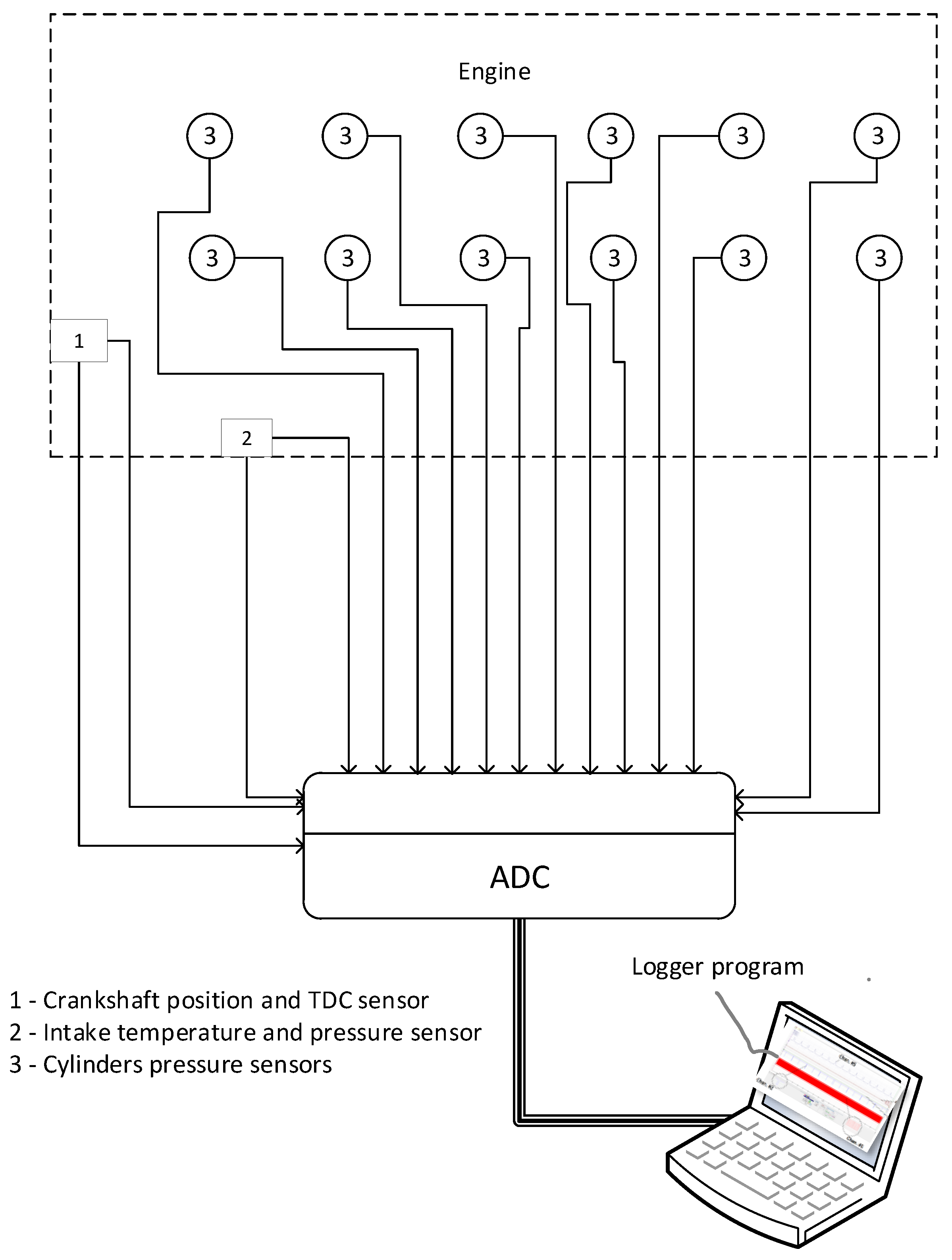
The inputs to the analytical model comprise (a) engine design parameters and operating settings, and (b) fuel thermo-chemical properties used for state-equation closure and heat release calculation. These data are summarized in Table 2. The system includes the following sensors: crankshaft position and TDC sensor ZF GS100101 (ZF Friedrichshafen AG, Friedrichshafen, Germany), air temperature and pressure sensor DS-G3-TF (Bosch, Gerlingen, Germany), and cylinder pressure sensors METZGER 0906488 (METZGER, Filderstadt, Germany), (see Figure 1). Visual registration of the main generator current and voltage was also performed synchronously, which allowed for determining the engine’s effective power.

Table 2.
Input data for processing the experimental results.
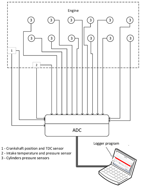
Figure 1.
Schematic diagram of the measuring system: 1—crankshaft position and TDC sensor (ZF GS100101); 2—air temperature and pressure sensor (DS-G3-TF); 3—cylinder pressure sensors (METZGER 0906488 (OE BMW 13 62 8 570 670)).
The sequence of calculations for mathematical analysis is as follows:
- 1.
- Air flow rate through the engine, kg/hwhere —fuel consumption, kg/h, —excess air ratio.
- 2.
- Cycle fuel supply, kg/cyclewhere n is the engine crankshaft speed, min−1.
- 3.
- Working body content in the cylinder, mol
- 4.
- Current cylinder volume by crankshaft angle of rotation per cycle, m3where .
- 5.
- Current cylinder volume increment by crankshaft rotation angle per cycle, m3/deg
- 6.
- Average indicator pressure, Pa
- 7.
- Current temperature in the cylinder by crankshaft angle of rotation in the cycle, K
- 8.
- Current heat capacity of the working body in the cylinder by crankshaft angle of rotation in the cycle, kJ/kgK
- 9.
- Current heat transfer coefficient in the cycle kW/m2K
- 10.
- Area of the internal heat-absorbing surface of the cylinder, m2
- 11.
- Relative rate of heat removal in the cycle,
- 12.
- Relative rate of effective heat releasewhere —increment of pressure in the cylinder, Pa/deg, —increment of current heat capacity of working body in the cylinder by crankshaft rotation angle in the cycle, kJ/(kmol K deg).
- 13.
- Relative combustion rate of fuel
- 14.
- Relative integral law of fuel burn-up
The given methodology was used in the present work to analyze experimental indicator diagrams and to determine the main indicator parameters.
3. Results and Discussion
To establish baseline indicated performance for the EMD 12-645E3C, the engine was tested in situ within a CIE Class 071 locomotive on a rheostat (load-bank) test stand. Measurements were acquired at operating points corresponding to the standard engine rating curve for diesel–electric locomotives. The schematic of the instrumentation and data-acquisition layout is shown in Figure 1.
3.1. Measurement Results and Their Processing
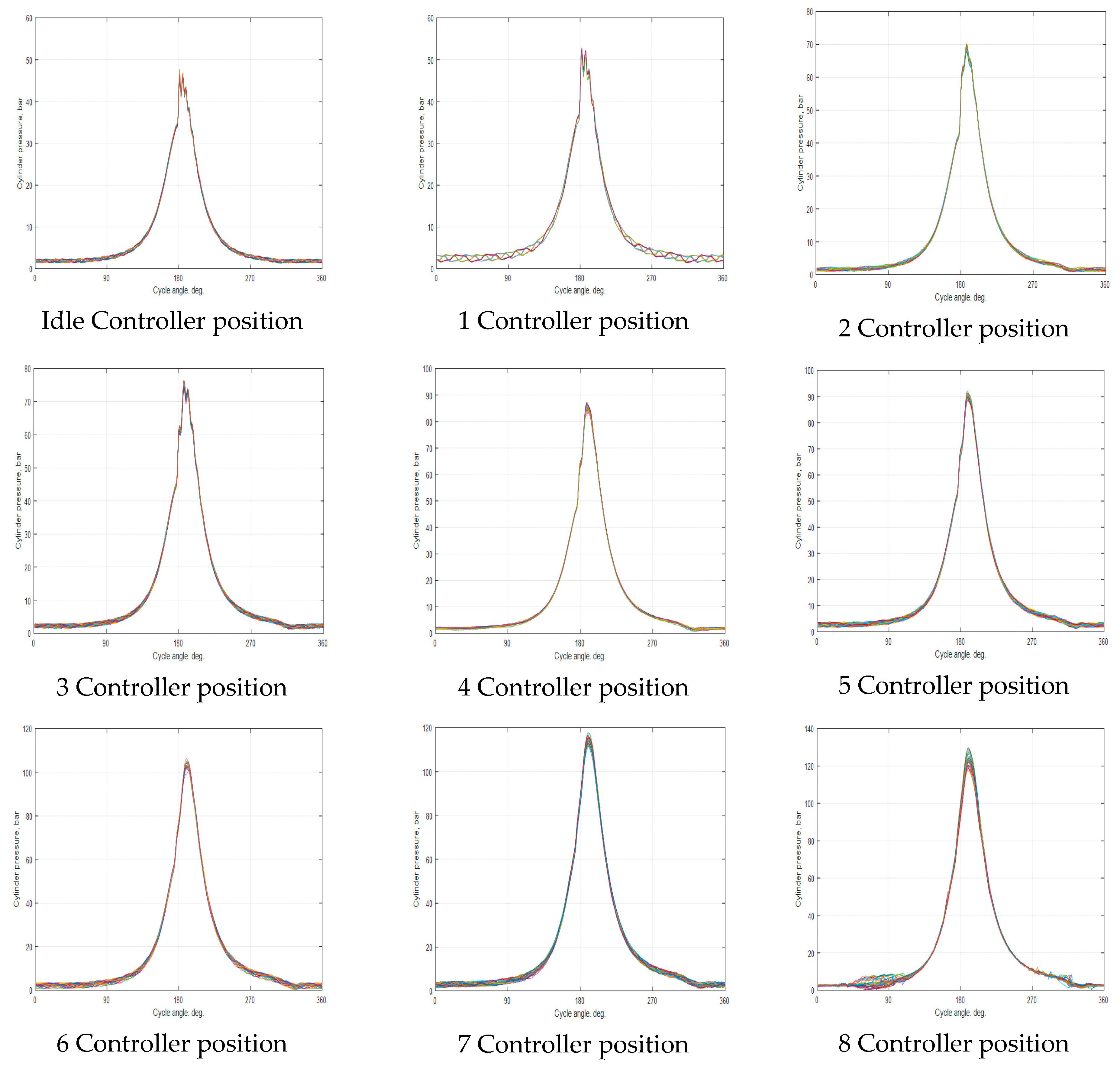
As a result of signal registration during locomotive bench tests, the following current engine operation parameters were obtained: effective power (kW), engine speed (RPM), intake pressure (MPa), intake temperature (K), cylinder pressure (MPa) for all 9 positions of the locomotive throttle controller position.
Their values are shown in Table 3 and Figure 2. Table 3 also shows the confidence interval of the parameter values determined when analyzing the indicator diagrams, based on the standard deviation of the normal law of statistical distribution.

Table 3.
Measured diesel engine operating parameters.
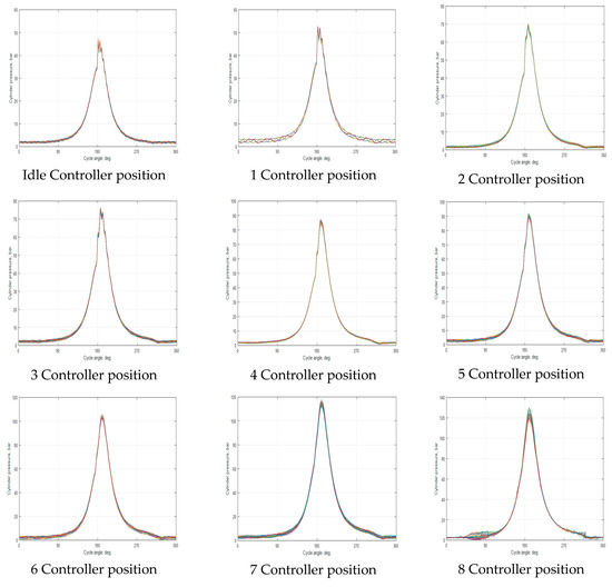
Figure 2.
Cylinder pressure variation based on controller position.
Figure 2 shows graphs of experimental indicator diagrams of 38 consecutive operating cycles at engine operation in different modes. These indicator diagrams are the basis for the performed analytical study. Figure 2 shows these indicator diagrams illustratively.
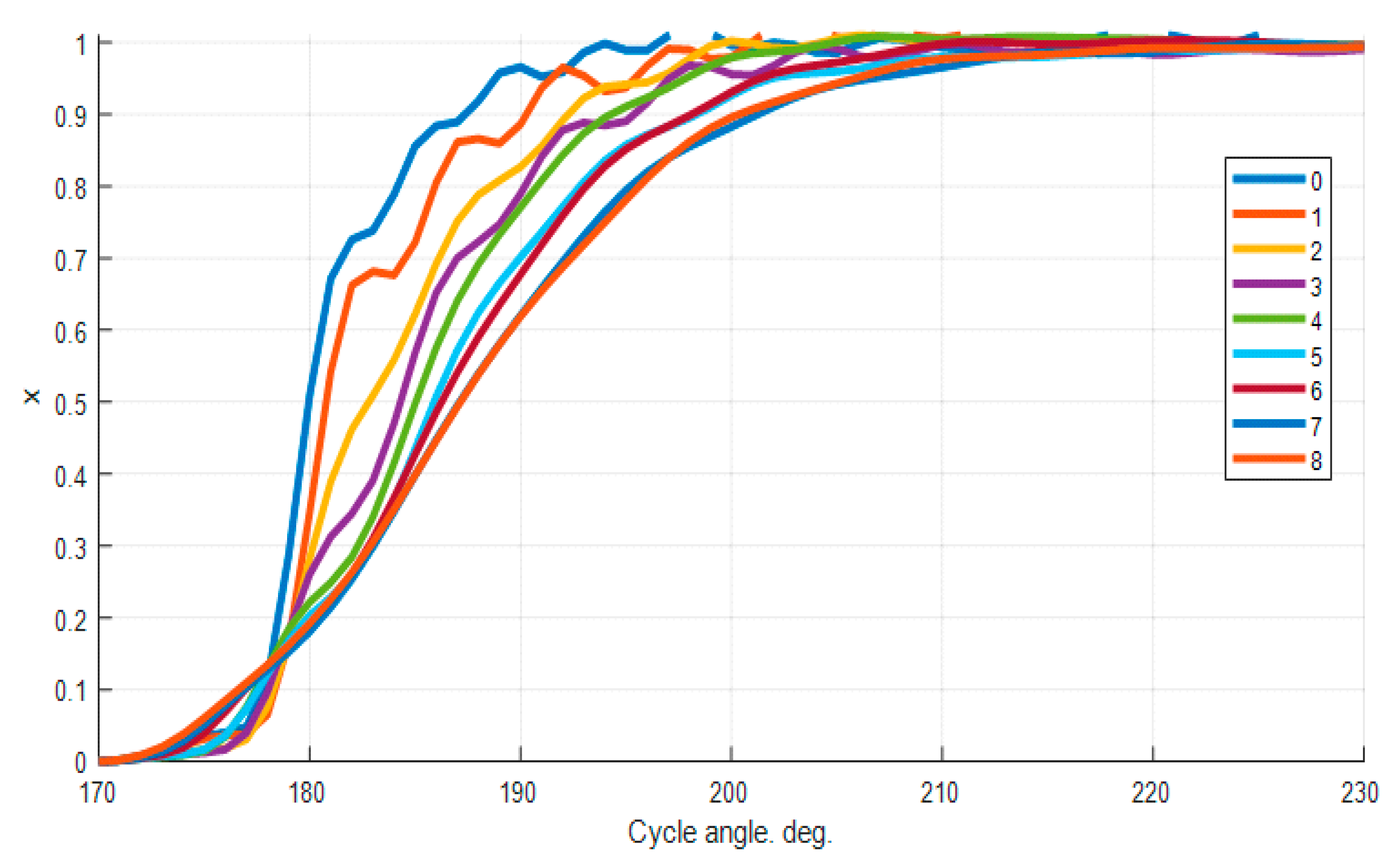
As a result of analytical processing of these signals, the following engine operation parameters are obtained: peak fire pressure (MPa), peak fire pressure (angle, deg), IMEP, (MPa), peak pressure rise (MPa/deg), start of combustion (SOC) angle (deg), end of combustion (EOC) angle (deg), which are summarized in Table 3. Parameters of heat release—integral law of combustion in the cylinder, obtained as a result of this analytical processing of indicator diagrams, are shown in Figure 3.
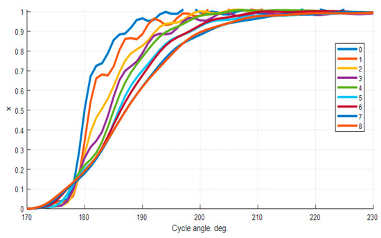
Figure 3.
Integral dependences of relative fuel burn-up.
The integral combustion law shows the relative amount of fuel burned in the cylinder by a certain moment of the cycle (crankshaft angle of rotation). Obviously, the condition x = 1 is fulfilled at the end of combustion (i.e., all fuel is burnt out). The moment of combustion start is determined by the condition x > 0. The graphs in Figure 3 show that the integral laws of fuel combustion in a diesel cylinder vary depending on its operating mode (load). Thus, when operating at controller positions 0, 1, or 2, where fuel delivery is minimal, combustion duration is 20–25 degrees of crankshaft rotation. It is also clear that combustion duration gradually increases with increasing load, reaching 55–60 degrees, which corresponds to controller positions 6–8. Furthermore, it could be observed that combustion begins earlier at higher load modes.
The above results of the analysis of experimental indicator diagrams served as a basis for the compilation and identification of the mathematical model of the EMD 12-645E3C engine, including its operation on hydrogen fuel.
3.2. Results of Mathematical Modeling of Hydrogen-Fueled Engine
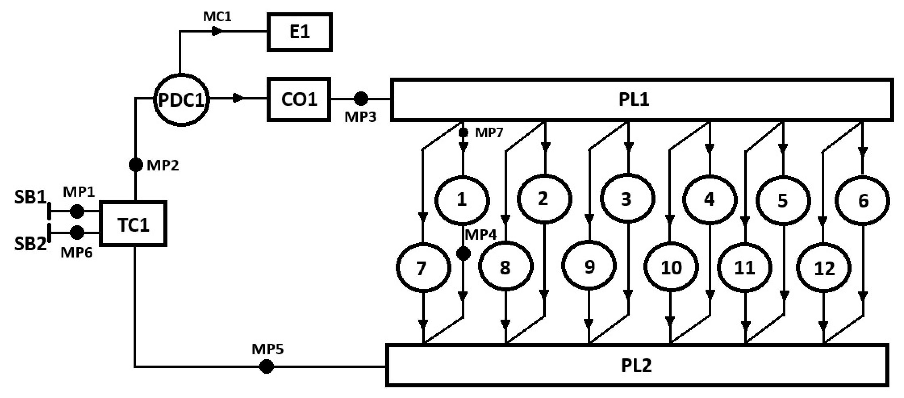
The schematic and composition of the mathematical model of the EMD 12-645E3C engine are shown in Figure 4. The following diagram shows the individual engine components: E1—engine as a unit, TC1—turbocharger, MC1—mechanical drive, PDC1—driven compressor, CO1—charge air cooler, PL1—intake manifold, C1-C12—engine cylinders, PL2—exhaust manifold, MP1-MP7—measurement points of parameters, SB1—inlet boundary conditions, SB2—outlet boundary conditions.
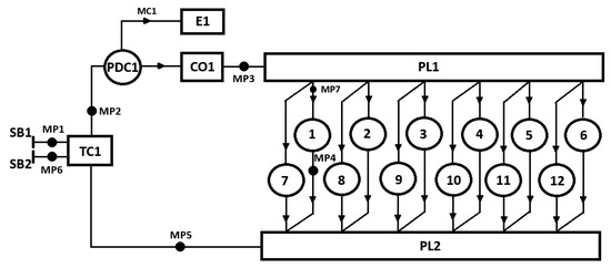
Figure 4.
Calculation diagram of the mathematical model of the EMD 12-645E3C engine.
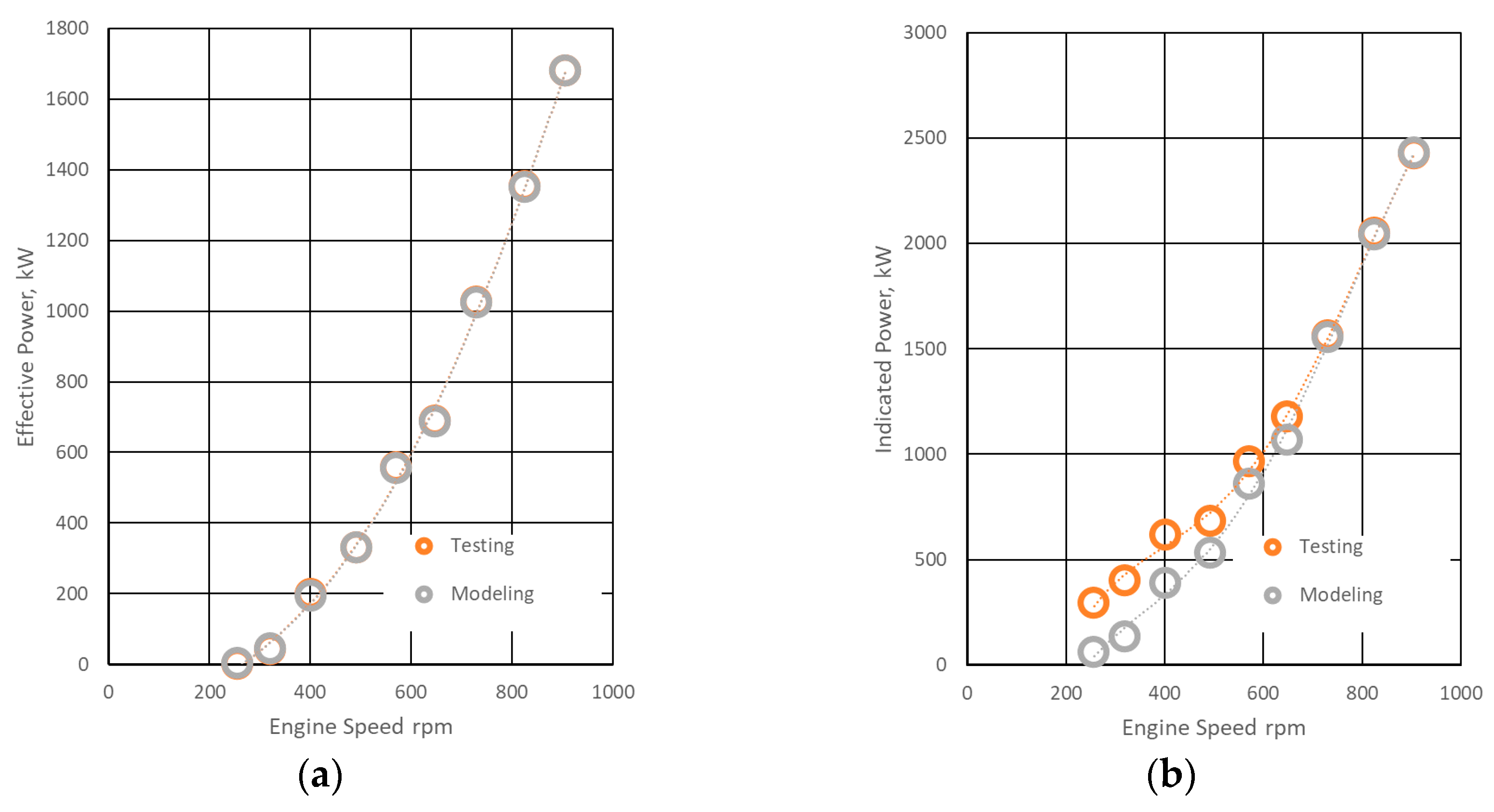
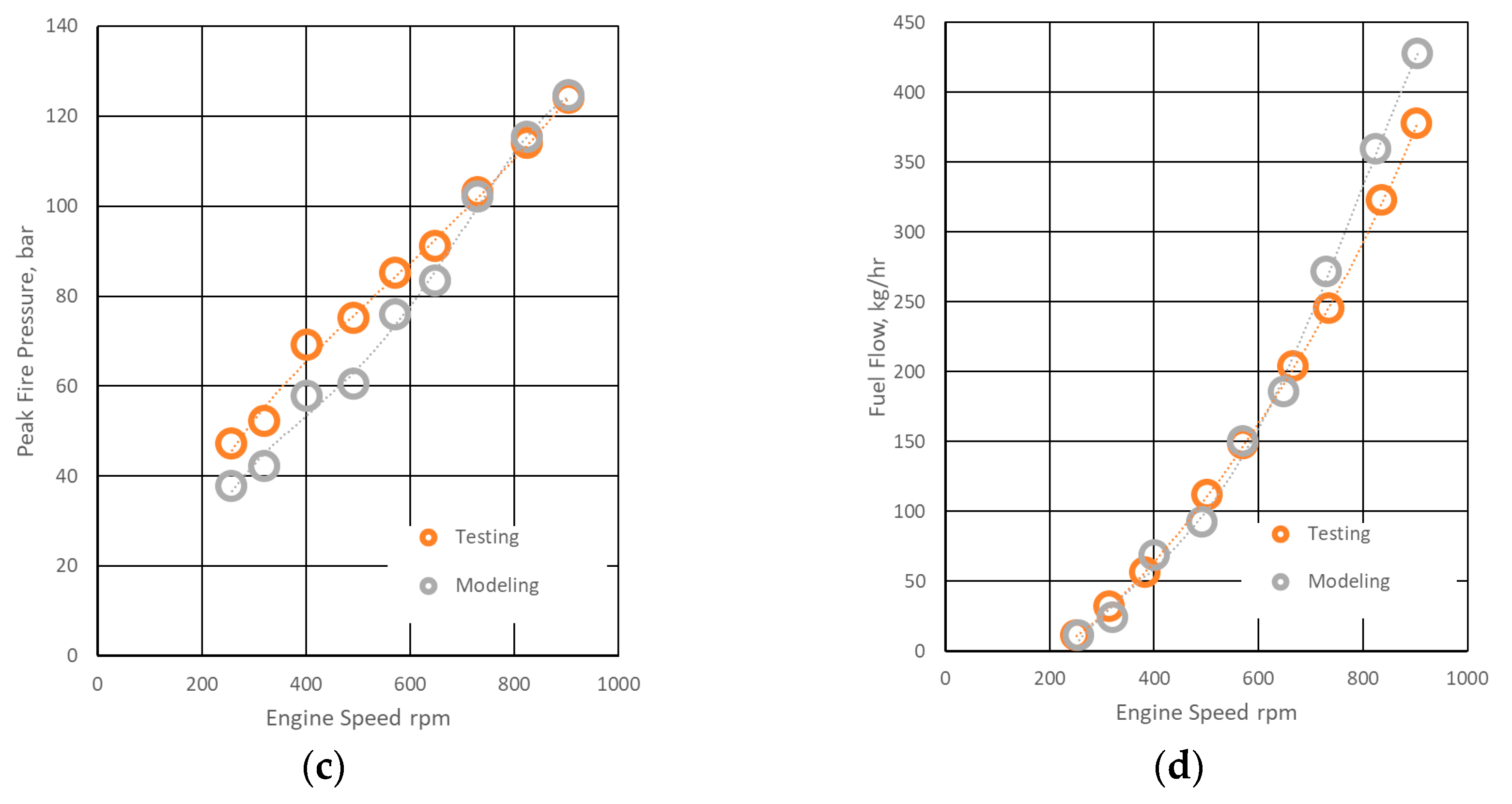
The outcomes of the diesel-engine simulation are summarized in Table 4 and Figure 5. This simulation stage served to calibrate the model parameters and to verify the adequacy of the mathematical formulation against the baseline measurements. As is evident from Table 4 and Figure 5, and in direct comparison with the experimental dataset in Table 3, the model reproduces both the indicated and brake (effective) performance metrics across all operating points of the locomotive rating curve.

Table 4.
Diesel engine modeling results.
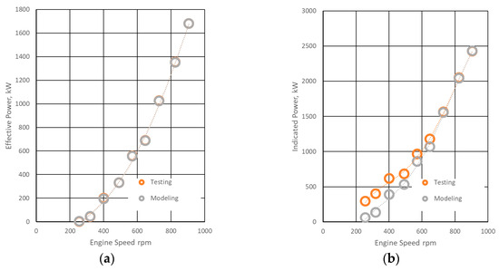
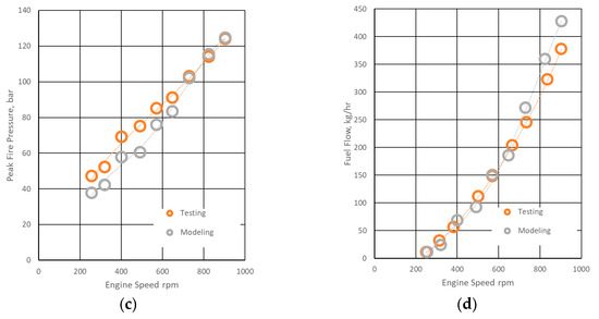
Figure 5.
Diesel engine modeling results: (a)—effective power; (b)—indicated power; (c)—peak fire pressure; (d)—fuel flow.
Across the tested modes, deviations between calculated and measured quantities remain within the confidence intervals reported for the corresponding experimental values in Table 3. The model captures the load-dependent trends without discernible systematic bias, and the magnitude of the residuals is consistent with the stated measurement uncertainty. These results support the adequacy of the calibrated model for subsequent analyses, including fuel-substitution scenarios and sensitivity studies.
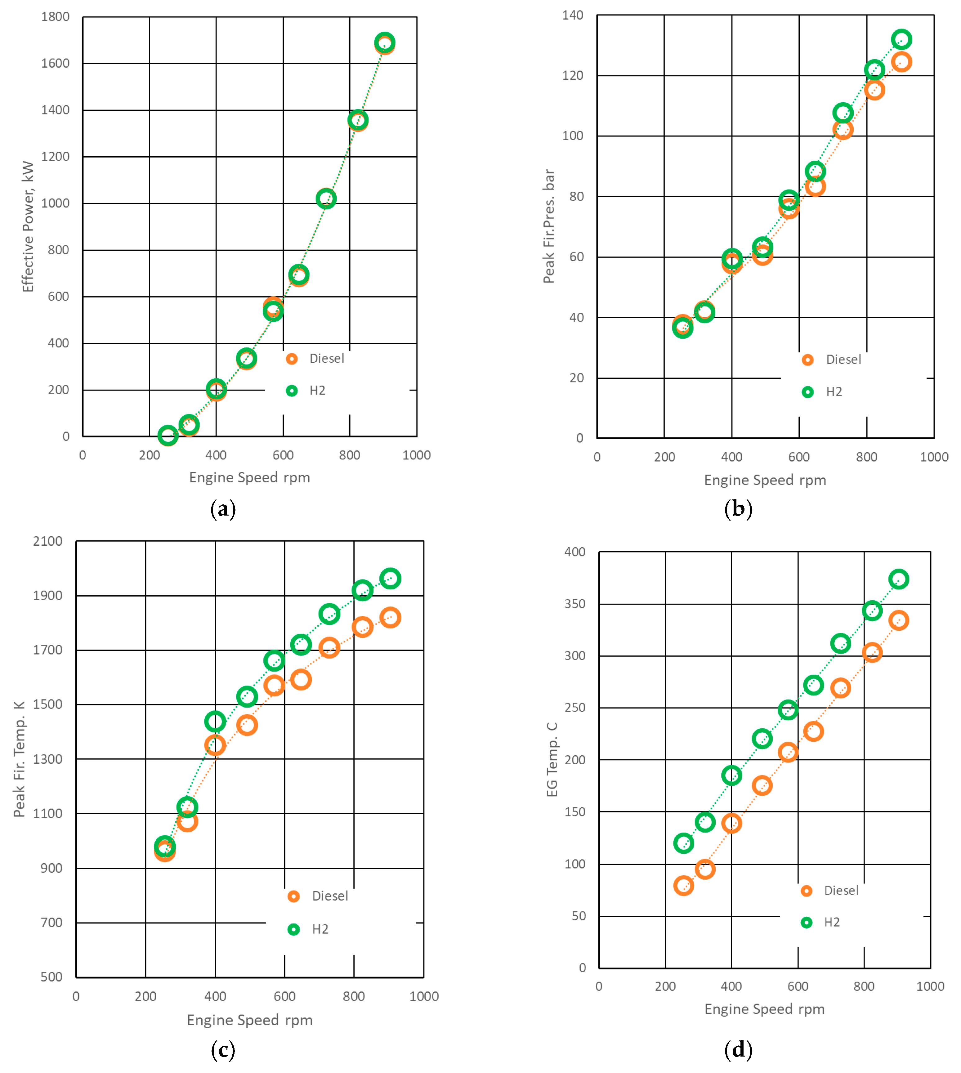
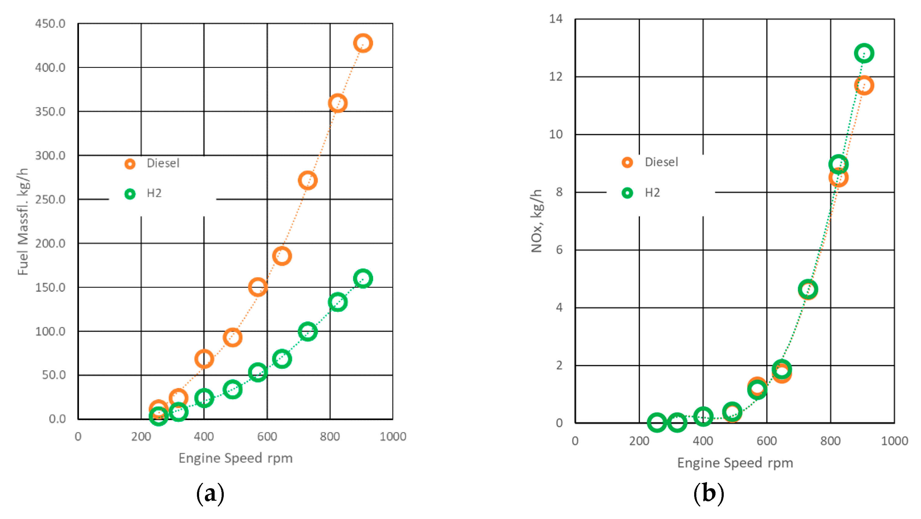
The simulation results of the hydrogen engine are shown in Table 5 and compared to the performance of the diesel engine in Figure 6 and Figure 7. From these data and their comparisons, conclusions can be drawn about the differences in engine performance for both fuels, which will be useful for further evaluation of their application in real-world applications.

Table 5.
Hydrogen engine modeling results.
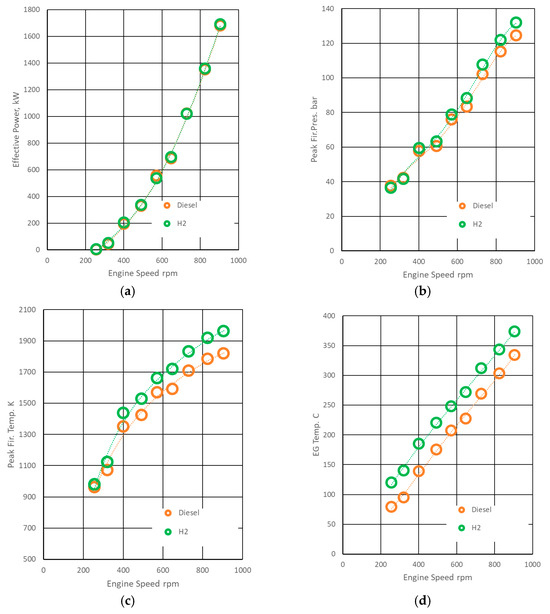
Figure 6.
Hydrogen engine modeling results: (a)—effective power; (b)—peak fire pressure; (c)—peak fire temperature; (d)—EG temperature.
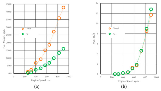
Figure 7.
Hydrogen engine modeling results for: (a)—fuel mass flow, (b)—NOx flow.
From the calibrated model and its comparison with test data (Table 3, Table 4 and Table 5), we infer the principal differences in engine behavior between hydrogen and diesel operation at matched effective power across the full locomotive rating curve (see Figure 6).
- Peak cylinder pressure (p_max): an increase of 3–6%, most pronounced at higher crankshaft speeds, consistent with faster global heat-release on hydrogen. This has implications for mechanical loading (head clamping, bearing loads) and should be reflected in fatigue and margin assessments.
- In-cylinder and exhaust temperatures: cycle-averaged gas temperatures rise by ≈5–8% in-cylinder and ≈12–20% at the turbine/exhaust, affecting combustion-chamber thermal fluxes, turbocharger turbine-inlet margins, and exhaust system material selection/insulation.
- Mass fuel flow: the hydrogen mass flow required to hold the same brake output is substantially lower than for diesel, primarily due to hydrogen’s higher lower heating value (LHV).
3.3. Analysis of the Dependence of Hydrogen Fuel Consumption on the Operating Mode
As shown in Figure 7a and Table 4 and Table 5, the equivalent hydrogen mass flow is typically 2.7–2.8× lower than that of diesel at matched effective power. This aligns with the ratio of the lower heating values (120 MJ·kg−1 for hydrogen versus 42.5 MJ·kg−1 for diesel; ratio ≈ 2.82). At low-power (light-load) positions, the observed ratio increase of 3.2–4.4 indicates comparatively higher apparent efficiency of in-cylinder processes on hydrogen in these regimes (reduced wall quench, lower pumping losses).
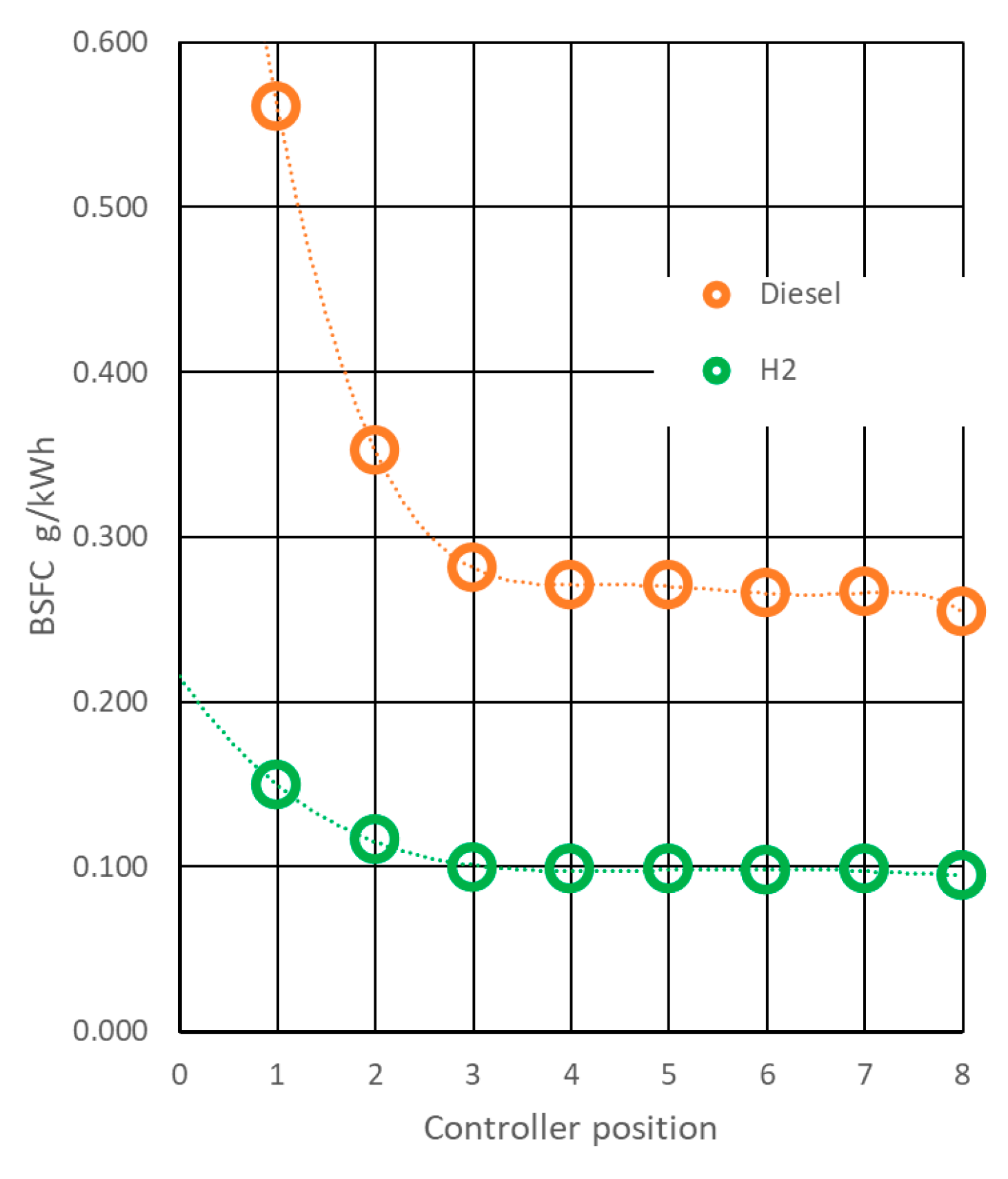
Mapping the mode-wise mass flows to effective power yields the brake-specific fuel consumption (BSFC) trends in Figure 8. As expected, idle (position 0) produces negligible effective power, so BSFC tends to be infinite. For mid–high load (positions 3–8), BSFC is nearly invariant and scales with the LHV ratio noted above. Study showed that specific effective consumption of diesel fuel is 260–270 g/kWh, and hydrogen is 90–100 g/kWh.
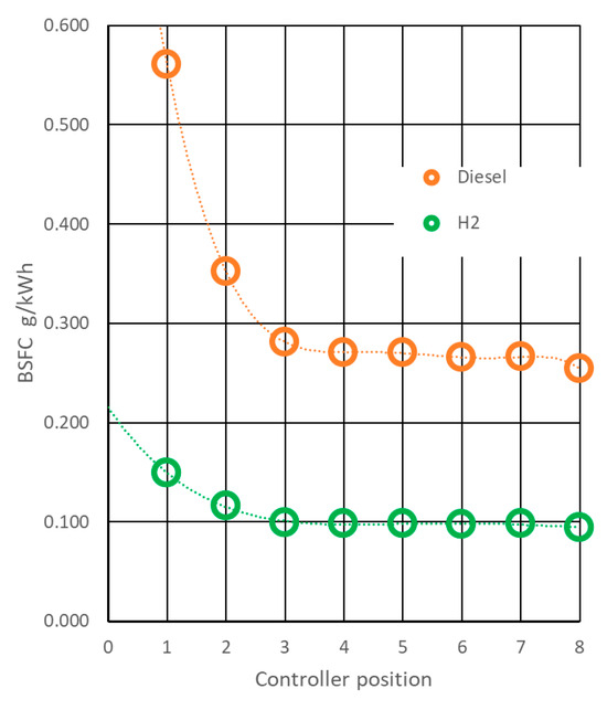
Figure 8.
Break specific fuel consumption by diesel locomotive characteristic.
For an integral (duty-cycle-weighted) estimate of locomotive fuel use, it is rational to weight the mode-wise flows by the relative time spent at each controller position. Because detailed time-at-notch statistics for CIE 071 are not available in the sources consulted, we adopt operator data for the GE C36-7i as shown in Table 6 and apply a simple weighting formula. On this basis, the dependence of flow on controller position (Figure 9) and the corresponding integral hourly consumption (Table 6) are obtained:

Table 6.
Operational fuel consumption of locomotive.
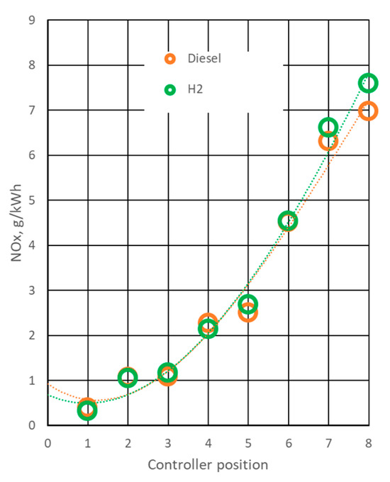
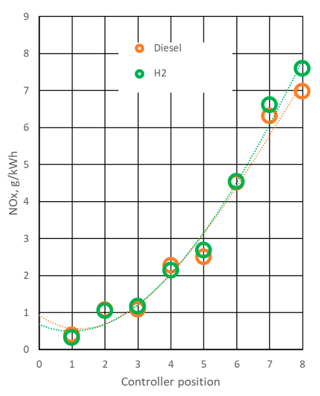
Figure 9.
NOx emissions by diesel locomotive characteristic.
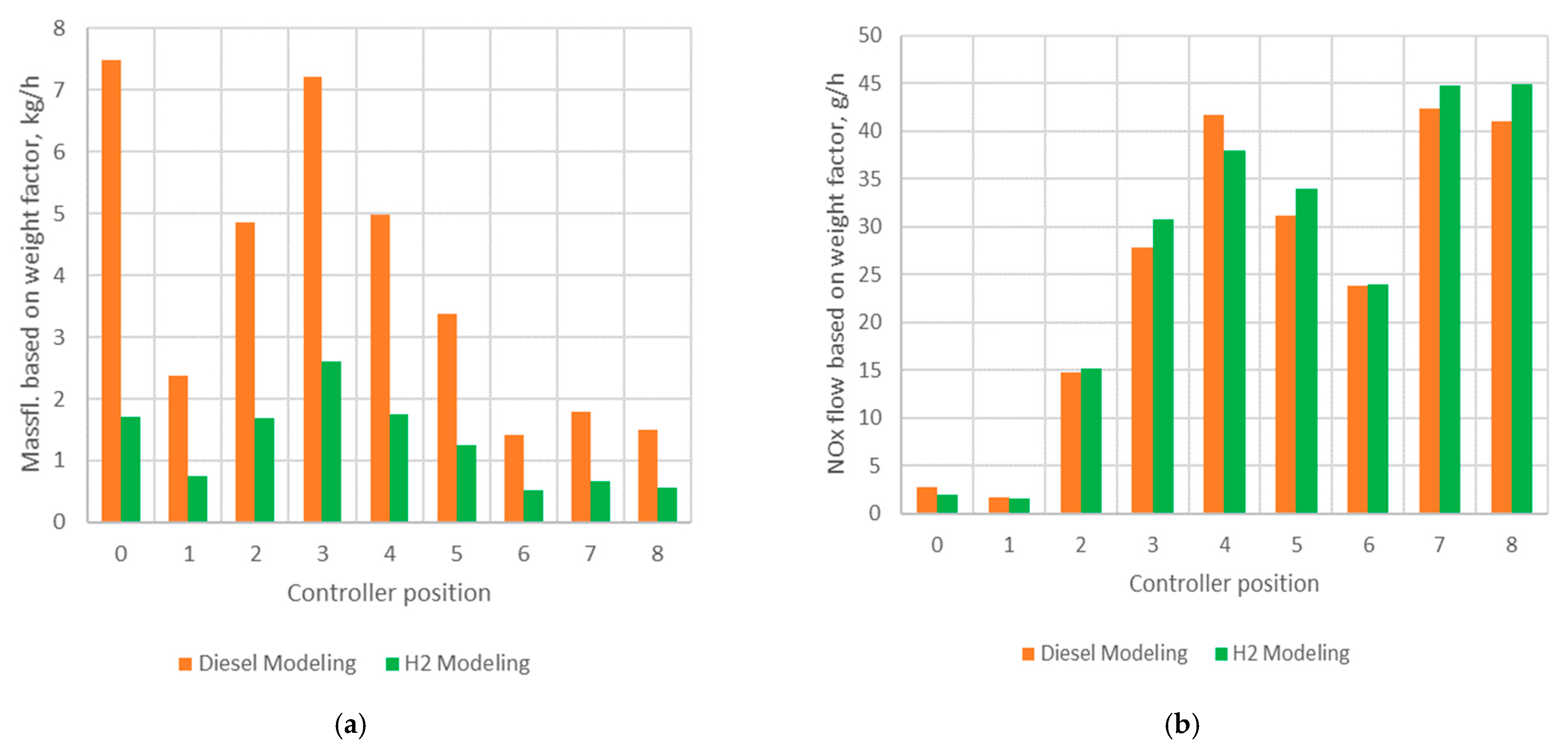
Using these data, the dependence of instantaneous fuel mass flow on controller (throttle) position is shown (Figure 10a), and the duty-cycle-weighted integral flow rate can be computed by accounting for the running time at each position. The time-weighted representation makes it possible to visualize which operating modes use fuel most efficiently and which require optimization. As shown from the histogram in Figure 10a, the overall trend in fuel consumption across individual modes is equidistant when using both diesel and hydrogen. Moreover, modes corresponding to idle (controller position zero) and light loads (positions two to five) are the locomotive’s primary fuel consumers, and these are the primary targets in case of optimization of the working process.
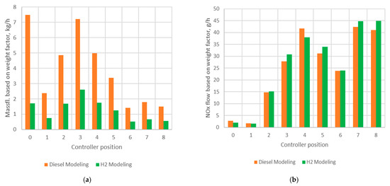
Figure 10.
Diesel and hydrogen modeling results: (a)—fuel mass flow based on weight factor at different controller positions; (b)—NOx flow based on weight factor at different controller positions.
Thus, the operational emissions of nitrogen oxides increase by 3.5% when using hydrogen, and an increase is observed at higher controller positions (see Table 7). This is explained by the higher adiabatic flame temperature of hydrogen in the cylinder. In overall hydrogen impact on the increase in NOx emissions could also be a combination of many operational factors, such as engine load, speed, combustion-system design, as well as fuel injection parameters [26]. NOx flow based on the weight factor at different controller positions is also calculated and reflected in Figure 10b.

Table 7.
NOx emissions of locomotive.
In addition, the obtained values of integral consumption of hydrogen fuel—11.5 kg/h vs. diesel fuel—35 kg/h, allow:
- Forecast the cost of operating a hydrogen locomotive based on a market cost of hydrogen of $1.5–3/kg and a diesel cost of $1.5–2.1/kg. The average operating cost of fuel for the locomotive when using diesel fuel will be 35 × 1.5–2.1) = 53–74 dollars per hour, and for hydrogen, 11.5 × (1.5–3) = 17–34 dollars per hour. Thus, the economy will be 35–40 dollars per hour.
- Estimate the amount of its required stock on board the crew. To maintain the locomotive’s autonomous cruising range, it is necessary to maintain a hydrogen reserve on board as fuel (taking into account the thermal equivalent): 11.5/35 × 120,000/42,000 × 100% = 94% of the mass of diesel fuel initially contained on board. Accordingly, knowing the estimated hydrogen reserve on board and solving the inverse problem, it is possible to predict or design the locomotive’s autonomous cruising range.
- Conclude that the energy resource is saved because the ratio of 35/11.5 = 3.04 is greater than the thermal equivalent in calorific value of diesel and hydrogen, which is 2.82.
4. Conclusions
The research conducted in this paper has shown that the use of hydrogen as a fuel for the diesel locomotive internal combustion engine used in passenger or freight service will not lead to deterioration of its operating parameters and will not reduce the reliability of the design. In particular:
- Peak combustion pressure. Switching to hydrogen increases in maximum in-cylinder pressure by ≈3–6%, most notably at high-power settings. This rise is modest and, based on typical design margins for the engine family, is not expected to materially increase in structural loading; nonetheless, it should be verified against head clamping, bearing loads, and fatigue life.
- Gas temperatures. Cycle-averaged in-cylinder and exhaust temperatures show slight increases of ≈5–8% and ≈12–20%. These deltas can be accommodated in combustion-chamber and exhaust-system design (materials, cooling, insulation, and turbocharger turbine-inlet limits), with modifications if required.
- Fuel mass consumption and energy use. The hydrogen mass flow required at matched effective power is significantly lower than for diesel, consistent with hydrogen’s higher LHV. Even after accounting for the thermal equivalent, the integral operational mass consumption implies an ≈8% energy-resource saving, attributable primarily to improved operating processes at idle and low-load regimes (controller positions 0–3).
- Conversion feasibility. The technical and operational characteristics of the EMD 12-645E3C suggest good potential for conversion to hydrogen, provided targeted modifications are implemented to the fuel, control, and safety subsystems. Priority actions include:
- -
- Fuel-system replacement. Adopt a hydrogen injection system capable of tight, high-pressure delivery to the cylinder (e.g., direct gaseous injection), with precise timing and metering.
- -
- Combustion-chamber adaptation. Optimize chamber geometry and compression ratio to promote uniform hydrogen distribution at low excess-air ratios while mitigating knock/detonation risk.
- -
- Ignition-system design. Employ a high-energy, potentially multi-point ignition strategy to ensure robust flame initiation under lean or stratified conditions and to reduce detonation propensity.
- -
- Safety systems. Integrate enhanced leak detection, ventilation, and automatic hydrogen shut-off to prevent accumulation and possible ignition outside the cylinders; ensure fault diagnostics and interlocks across the fuel path.
Overall, bench-referenced modeling indicates that converting legacy medium-speed locomotive diesels such as the EMD 12-645E3C to hydrogen can preserve rated performance while keeping modest increases in peak pressure and temperature within manageable design margins, and can yield duty-cycle efficiency gains—with corresponding cost and emissions benefits—provided the fuel, ignition, and safety systems are rigorously redesigned and validated.
Author Contributions
Conceptualization, P.D. and A.P.; methodology, P.D. and A.P.; computation A.P.; validation, P.D., A.P., and R.S.; formal analysis, P.D. and A.P.; investigation, P.D., A.P., and R.S.; resources, P.D.; data curation, A.P.; writing—original draft preparation, P.D. and A.P.; writing—review and editing, P.D. and R.S.; visualization, A.P. and R.S.; supervision, P.D.; project administration, P.D. All authors have read and agreed to the published version of the manuscript.
Funding
Agreement concluded on 12 July 2024 between the Competence Centre and the Central Finance and Contracting Agency on the implementation of the European Union Recovery Fund Project No. 2.2.1.3.i.0/1/24/A/CFLA/007, Study No. D.3.1 “Passenger train hydrogen internal combustion engine control system”.
Data Availability Statement
Data will be made available upon request.
Conflicts of Interest
Authors Petro Dumenko and Andriy Prokhorenko were employed by the company Digas Ltd. The remaining author declares that the research was conducted in the absence of any commercial or financial relationships that could be construed as a potential conflict of interest.
References
- Destatis. Road Transport: EU-Wide Carbon Dioxide Emissions Have Increased by 21% Since 1990. 2024. Available online: https://www.destatis.de/Europa/EN/Topic/Environment-energy/CarbonDioxideRoadTransport.html (accessed on 21 July 2025).
- Kowalski, P.; Kołodziejczak, K.; Frąckowiak, E. Hydrogen as an alternative energy source in railway vehicles. Rail Veh. Pojazdy Szyn. 2024, 3–4, 13–17. [Google Scholar] [CrossRef]
- Smigins, R.; Amatnieks, K.; Birkavs, A.; Kryshtopa, S. Performance and emissions of an agricultural diesel engine with hydrogen injection under different load modes. Agron. Res. 2025, 23, 195–207. [Google Scholar] [CrossRef]
- Staffell, I.; Scamman, D.; Velazquez Abad, A.; Balcombe, P.; Dodds, P.E.; Ekins, P.; Shah, N.; Ward, K.R. The role of hydrogen and fuel cells in the global energy system. Energy Environ. Sci. 2019, 12, 463–491. [Google Scholar] [CrossRef]
- Zhang, Y.; Tian, Z.; Jiang, K.; Hillmansen, S.; Roberts, C. Local and global sensitivity analysis for railway upgrading between hydrogen fuel cell and electrification. High-Speed Railw. 2024, 2, 219–229. [Google Scholar] [CrossRef]
- Sun, Y.; Anwar, M.; Hassan, N.M.S.; Spiryagin, M.; Cole, C. A review of hydrogen technologies and engineering solutions for railway vehicle design and operations. Rail. Eng. Sci. 2021, 29, 212–232. [Google Scholar] [CrossRef]
- Marjani, S.R.; Motaman, S.; Varasteh, H.; Yang, Z.; Clementson, J. Assessing hydrogen as an alternative fuel for rail transport—A case study. Sci. Rep. 2025, 15, 6449. [Google Scholar] [CrossRef] [PubMed]
- D’Acierno, L.; De Matteis, L.; Stefanelli, R. Adoption of Hydrogen in Railway Traction: Opportunities and Limits in the Case of Non-Electrified Railway Lines. Transp. Res. Procedia 2025, 90, 130–137. [Google Scholar] [CrossRef]
- Wright, M.L.; Lewis, A.C. Decarbonisation of heavy-duty diesel engines using hydrogen fuel: A review of the potential impact on NOx emissions. Environ. Sci. Atmos. 2022, 2, 852–866. [Google Scholar] [CrossRef]
- Atteridge, W.J.; Lloyd, S.A. Thoughts on use of hydrogen to power railway trains. Proc. Inst. Mech. Eng. Part A J. Power Energy 2021, 235, 306–316. [Google Scholar] [CrossRef]
- Kryshtopa, S.; Górski, K.; Longwic, R.; Smigins, R.; Kryshtopa, L.; Matijošius, J. Using Hydrogen Reactors to Improve the Diesel Engine Performance. Energies 2022, 15, 3024. [Google Scholar] [CrossRef]
- Goyal, H.; Jones, P.; Bajwa, A.; Parsons, D.; Akehurst, S.; Davy, M.H.; Leach, F.C.; Esposito, S. Design trends and challenges in hydrogen direct injection (H2DI) internal combustion engines—A review. Int. J. Hydrogen Energy 2024, 86, 1179–1194. [Google Scholar] [CrossRef]
- Regele, C.; Gackstatter, F.; Ortner, F.; Preuster, P.; Geißelbrecht, M. Simulation and optimization of a liquid organic hydrogen carrier based hydrogen train system. Energy Convers. Manag. 2025, 344, 120234. [Google Scholar] [CrossRef]
- D’Ovidio, G.; Ometto, A.; Valentini, O. A novel predictive power flow control strategy for hydrogen city rail train. Int. J. Hydrogen Energy 2020, 45, 4922–4931. [Google Scholar] [CrossRef]
- Pielecha, I.; Engelmann, D.; Czerwinski, J.; Merkisz, J. Use of hydrogen fuel in drive systems of rail vehicles. Rail Veh. Pojazdy Szyn. 2022, 1–2, 10–19. [Google Scholar] [CrossRef]
- Skabelund, B.B.; Jenkins, C.D.; Stechel, E.B.; Milcarek, R.J. Thermodynamic and emission analysis of a hydrogen/methane fueled gas turbine. Energy Convers. Manag. 2023, 19, 100394. [Google Scholar] [CrossRef]
- Molkov, V. Advances in hydrogen storage technologies. J. Loss Prev. Process Ind. 2025, 94, 105561. [Google Scholar] [CrossRef]
- Onorati, A.; Payri, R.; Vaglieco, B.M.; Agarwal, A.K.; Bae, C.; Bruneaux, G.; Canakci, M.; Gavaises, M.; Günthner, M.; Hasse, C.; et al. The role of hydrogen for future internal combustion engines. Int. J. Engine Res. 2022, 23, 529–540. [Google Scholar] [CrossRef]
- Szwaja, S.; Piotrowski, A.; Szwaja, M.; Musial, D. Thermodynamic Analysis of the Combustion Process in Hydrogen-Fueled Engines with EGR. Energies 2024, 17, 2833. [Google Scholar] [CrossRef]
- Sun, B.; Zhao, H.; Dong, X.; Teng, C.; Zhang, A.; Kong, S.; Zhou, J.; Zhang, X.-C.; Tu, S.-T. Current challenges in the utilization of hydrogen energy-a focused review on the issue of hydrogen-induced damage and embrittlement. Adv. Appl. Energy 2024, 14, 100168. [Google Scholar] [CrossRef]
- Nqodi, A.; Mosetlhe, T.C.; Yusuff, A.A. Advances in Hydrogen-Powered Trains: A Brief Report. Energies 2023, 16, 6715. [Google Scholar] [CrossRef]
- Stobnicki, P.; Gallas, D. Adoption of modern hydrogen technologies in rail transport. J. Ecol. Eng. 2022, 23, 84–91. [Google Scholar] [CrossRef]
- CSX Unveils Its First Hydrogen-Powered Locomotive in Collaboration with CPKC. Hydrogen Central. Available online: https://hydrogen-central.com/csx-unveils-its-first-hydrogen-powered-locomotive-in-collaboration-with-cpkc/ (accessed on 17 April 2024).
- Agency PTI. ‘India Made Hydrogen Fuel Train Engine More Powerful Than Others’: Ashwini Vaishnaw. Available online: https://www.news18.com/india/india-made-hydrogen-fuel-train-engine-more-powerful-than-others-ashwini-vaishnaw-9184255.html (accessed on 10 January 2025).
- Wang, Y.; Zhu, G.; Shen, Z.; Chen, L.; Kou, C.; Yang, D.; Chen, W.; Zuo, Q. Numerical study of active pre-combustion chamber structure on combustion performance and emission characteristics of jet ignition pure ammonia engine. Fuel 2026, 405, 136854. [Google Scholar] [CrossRef]
- Szwaja, S.; Naber, J.D. Performance characteristics of a hydrogen fuelled S.I. engine using timed manifold injection. Int. J. Hydrogen Energy 2013, 38, 12489–12496. [Google Scholar] [CrossRef]
Disclaimer/Publisher’s Note: The statements, opinions and data contained in all publications are solely those of the individual author(s) and contributor(s) and not of MDPI and/or the editor(s). MDPI and/or the editor(s) disclaim responsibility for any injury to people or property resulting from any ideas, methods, instructions or products referred to in the content. |
© 2025 by the authors. Licensee MDPI, Basel, Switzerland. This article is an open access article distributed under the terms and conditions of the Creative Commons Attribution (CC BY) license (https://creativecommons.org/licenses/by/4.0/).

