Abstract
With increasing attention paid to the development of natural gas hydrates, various mining methods have been studied. CO2-CH4 hydrate replacement has become one of the key research topics in the field of natural gas hydrate mining because it can overcome the disadvantage of traditional mining methods that easily lead to reservoir collapse and realize CO2 sequestration while extracting CH4. However, complex heat and mass transfer, as well as fluid migration, are involved in CO2-CH4 hydrate in situ replacement, and this method has the drawbacks of slower reaction rates and a lower replacement efficiency compared to traditional methods. Therefore, a substantial amount of experimental and simulation research is still needed to advance this method. This paper reviews the current research on CH4 recovery from CH4 hydrate by CO2 replacement. The main CO2-CH4 hydrate replacement mechanisms are summarized according to whether the hydrate cage structure is disrupted. Numerical simulation studies based on the above replacement mechanisms are introduced and compared in detail. The effects of various replacement methods, such as soaking replacement and dynamic replacement, as well as factors including the presence of initial water, reservoir permeability, temperature, and pressure on the replacement reaction, are summarized. Additionally, existing pore-scale replacement studies are reviewed, highlighting the necessity of pore-scale research on CO2-CH4 hydrate replacement reactions, pointing out the shortcomings of current pore-scale studies, and proposing suggestions for future research directions. This work provides a reference for the development of the CO2-CH4 hydrate replacement method and the realization of its industrial applications.
1. Introduction
Natural gas hydrates (NGHs), also known as “combustible ice”, are formed under low temperature and high pressure and appear as an ice-like solid. If more than 99% of the guest molecules trapped within the water lattice are CH4, the NGH is specifically referred to as CH4 hydrate. NGHs are widely distributed in subsea sediment layers and terrestrial permafrost regions and are considered an efficient, clean energy source. Therefore, the efficient development and utilization of NGH resources have been studied worldwide, with successful pilot production conducted in multiple countries.
On the other hand, a series of climate issues are attributed to CO2 accumulation in the atmosphere. Therefore, CO2 capture and storage (CCS) has also received increasing attention. Due to the stability of CO2 hydrate at ocean/permafrost depths, sequestration of CO2 in the form of hydrates is an advantageous option [1].
CO2-CH4 hydrate replacement is a method that involves injecting CO2 into hydrate reservoirs to produce CH4 and sequester CO2 in the original reservoir in the form of hydrates. Consequently, this method has garnered significant attention in recent years [2]. Generally, two processes are involved in CO2-CH4 replacement in the CH4 hydrate. First, CO2 is continuously injected into the CH4 hydrate reservoir through the inlet to displace CH4 in the pores. Second, when the pores are saturated with CO2 and the proportion of the outlet gas components remains essentially unchanged, the inlet and outlet are closed for a full reaction. Based on the characteristics of these two processes, CO2 replacement can be categorized into dynamic replacement and soaking replacement [3].
The CO2-CH4 hydrate replacement mechanism has remained controversial for a long time. One view holds that during the replacement process, the equilibrium of CH4 hydrate is disrupted, causing CH4 hydrate to dissociate and release CH4 and water molecules. The released water recombines with CO2 and part of the CH4 to form CO2/CH4 mixed hydrates [4]. Another view holds that CH4 hydrate does not dissociate during the replacement process, and its water lattice structure remains intact, with CO2 directly replacing CH4 molecules within the cages [5]. The latest view is based on the above two views and holds that the dissociation of CH4 hydrate is determined by the thermodynamic conditions and environmental factors during the replacement process [6]. Various models have been established from different perspectives by scholars to describe replacement mechanisms. These models include kinetic models based on the hydrate dissociation/formation mechanism, non-equilibrium thermodynamic models based on the guest molecule replacement mechanism, and so on. Meanwhile, the views on the replacement mechanism all suggest that the formation of mixed hydrates will restrict the interphase mass transfer of guest molecules, forcing them to diffuse through the mixed hydrate layer to continue the replacement reaction. This diffusion process of CH4 and CO2 molecules through mixed hydrates is referred to as diffusion-limited mass transfer [7].
In a word, multiphase and multicomponent systems are involved in CO2-CH4 hydrate replacement reactions, including fluid migration, hydrate dissociation/formation, interphase component transport, etc. During the replacement process, energy is released or absorbed by hydrate formation/dissociation, which, in turn, affects the reaction. In addition, CO2-CH4 hydrate replacement generally takes place in porous media and can be affected by thermodynamic properties, permeability, and pore microstructure of the sediment, which makes the replacement process more complicated. Current studies include intrinsic replacement mechanisms [8], phase equilibrium conditions of substances participating in the replacement reaction [9], and sensitivity of replacement rates to relevant parameters [10]. The influence of reservoir properties on CO2-CH4 hydrate replacement [11] and the mechanical intensity of sediment have also been explored [12].
Although current research has yielded a wealth of meaningful results, the inherent limitations of the CO2-CH4 hydrate replacement method remain unresolved. Conclusions regarding the influence of relevant factors on the replacement process are inconsistent. These issues may be related to the complexity of CO2-CH4 hydrate replacement or to the porous environment in which the reaction occurs. Therefore, this paper begins with fundamental replacement theories and models, analyzes the debates in existing research on CO2-CH4 hydrate replacement mechanisms and the factors affecting replacement efficiency, and aims to help identify methods for improving replacement efficiency. Furthermore, in spite of the necessity of pore-scale research on CO2-CH4 hydrate replacement, the current studies on the pore-scale replacement reaction are limited and scattered. This paper provides an overview of pore-scale studies, and recommendations for future research directions are proposed.
2. NGHs and Extraction Methods
2.1. Essential Properties of NGHs
NGHs burn when exposed to fire, producing CO2 and water as combustion products, with almost no residue. About 164 m3 of natural gas and 0.8 m3 of water can be produced when 1 m3 of NGHs completely dissociates. The density of NGHs is slightly lower than that of ice, but higher than that of hydrocarbon liquid, generally between 0.8 and 1.0 g/cm3, and their shear coefficient and thermal conductivity are lower than those of ice.
In NGHs, water molecules are connected through hydrogen bonds, forming cage-like structures of various sizes. The cage structures combine to form crystal cells with different configurations. Then, the guest molecules reside in the cavities of the water cages. There are many kinds of guest molecules capable of forming hydrates, including small-molecule hydrocarbons, CO2, N2, H2, H2S, and so on. The hydrate structures vary depending on the guest molecules. There are three common types of hydrate crystal structures, as follows: Structure I, Structure II, and Structure H. CH4 hydrate, CO2 hydrate, and the CO2/CH4 mixed hydrates involved in CO2-CH4 hydrate replacement are all thought to be Structure I hydrates. The molecular formula for Type I hydrate is 6L·2S·46H2O, where L and S represent large cages and small cages, respectively. In CH4 hydrate, large and small cages are occupied by CH4 molecules [13]. In CO2 hydrate, large cages and some of the small cages are occupied [14]. And in the CO2/CH4 mixed hydrates, large cages are occupied by CO2 molecules, while small cages are occupied by CH4 molecules [15].
2.2. Formation and Distribution of NGHs
The general molecular formula of NGHs can be written as M·NMH2O, where M and NM are the hydrate guest molecule and hydration number, respectively. Organic matter deposited beneath the seabed and continental rock layers decomposes under the action of microorganisms, producing sufficient gas [16], which provides the raw material for hydrate formation. Figure 1 shows a schematic diagram of NGH particle formation redrawn from Davies et al. [17]. As shown in the diagram, under conditions suitable for hydrate formation and with abundant gas, NGHs begin to be generated at the gas–liquid interface. Subsequently, due to the hindrance of the formed hydrate layer between the gas and the liquid phase, further hydrate formation is restricted, and the formation rate gradually slows down [17]. In porous media, hydrates exist by coating the grains when the gas phase is sufficient and the surface of the porous media particles is hydrophilic. After the hydrate formation process, a small amount of water will exist below the hydrate layer [18]. However, when the gas phase is scarce or even dissolved in the aqueous phase, or when the surface of the porous media particles is hydrophobic, hydrates are formed in the porous media in the form of pore-filling or a combination of pore-filling and partial grain-coating [18].
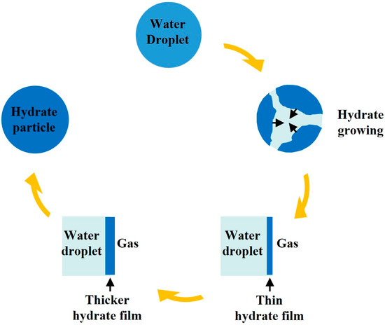
Figure 1.
Schematic diagram of NGH particle formation redrawn from Davies et al. [17].
The suitable temperature for hydrate formation ranges between 0 and 10 °C. The seabed temperature is generally around 4 °C, and the permafrost layers can also provide the low temperatures needed for hydrate formation. But in deeper rock layers, temperatures tend to rise due to geothermal effects. At the ocean floor and in rock layers above 800 m deep on land, it is easy to reach the pressure necessary for NGH formation. In summary, NGHs are widely distributed in continental and island slope areas, polar continental shelves, plateau permafrost areas, and some deep-water environments.
2.3. CH4 Hydrate Extraction Methods
Most NGHs are found in porous media such as mud, sand, and rock in nature, with a high extraction difficulty due to complex geological conditions. Therefore, extensive research on NGH extraction methods has been conducted worldwide. However, the extraction of NGHs is still in the pilot testing stage, and further research is still needed before commercial extraction can be achieved.
Most of the guest molecules of NGHs found in nature are CH4, so the research on NGHs extraction is mainly carried out around CH4 hydrate. The CH4 hydrate, CO2 hydrate, and CO2 phase equilibrium curves are displayed in Figure 2. As shown in Figure 2, when the environmental temperature and pressure are above the hydrate equilibrium curve, the hydrate remains in a stable state; conversely, the equilibrium state of the hydrate is disrupted, resulting in the decomposition of the hydrate into water and gas. Therefore, the essence of CH4 hydrate extraction is to disrupt its original thermodynamic equilibrium to release CH4 molecules. Traditional CH4 hydrate extraction methods include depressurization, thermal stimulation, and inhibitor injection. New extraction methods include CO2-CH4 hydrate replacement and the solid fluidization method [19]. A brief introduction to each method follows.
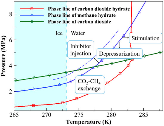
Figure 2.
Phase equilibrium curves of CH4 hydrate, CO2 hydrate, and liquid–gaseous CO2.
As shown in Figure 2, depressurization lowers the CH4 pressure to break the stable state of CH4 hydrate. Depressurization is relatively low-cost and easy to implement. These advantages render it the most promising approach for commercial extraction. This method had been adopted in field trials conducted in Canada, Japan, and China. However, depressurization also has some drawbacks, such as causing a temperature decrease, leading to the formation of ice and hydrates that block flow. Additionally, this method shares the common issue of rock deformation and collapse found in traditional extraction techniques [20]. The thermal stimulation method involves raising the temperature, thereby disrupting the phase equilibrium of CH4 hydrate. The process of thermal stimulation is simple and controllable, and its feasibility has been demonstrated in a field pilot test [21]. However, its drawbacks are also evident: compared to the depressurization method, this approach results in significant energy loss and has a lower extraction efficiency. The inhibitor injection method involves injecting chemical inhibitors, such as alcohols or electrolyte solutions, into the hydrate reservoir to alter the chemical environment of the hydrates. This change causes CH4 hydrate to become unstable [22]. Although the inhibitor injection method is simple and convenient, it is costly and prone to environmental pollution. Thus, this method is unsuitable for practical production. Unlike other methods, the solid hydrates are extracted directly by the use of the solid fluidization method. In this approach, the hydrates in the reservoir are first crushed into a slurry. Then, the hydrate-containing slurry is transported to shallow waters. During the lifting of the slurry, the hydrate decomposes due to the changes in temperature and pressure, and the CH4 is released. This method is suitable for shallow NGH deposits without a dense cap layer. In 2017, a field trial using solid fluidization was successfully conducted in Liwan, northern South China Sea [19].
The CO2-CH4 hydrate replacement method involves injecting CO2 into CH4 hydrate to release CH4, while simultaneously storing CO2 in the form of hydrates within the original reservoir. This method offers advantages beyond just CO2 sequestration. First, CO2 hydrate fills the pore spaces in the reservoir, which helps protect the reservoir structure and prevents rock deformation and collapse [20]. Second, since the exothermic heat of CO2 hydrate formation is 57.98 kJ/mol and the endothermic heat of CH4 hydrate dissociation is 54.49 kJ/mol [23], no additional heat needs to be supplied to the reservoir during CH4 hydrate extraction [24]. These advantages make CO2-CH4 hydrate replacement highly attractive. Its main drawbacks are that the replacement process is slow and has a low extraction efficiency. To overcome these drawbacks, hybrid extraction methods have been proposed to enhance the process of CO2-CH4 hydrate replacement. Through the combination of traditional mining methods and the CO2-CH4 hydrate replacement method, the advantages of each method can be utilized while compensating for their shortcomings [25].
Although the existing studies have yielded a large number of beneficial results, the practical application of the CO2-CH4 hydrate replacement method still requires a series of preparatory experiments and numerical simulation studies for support [26]. With the development of the CO2-CH4 hydrate replacement method, we should continue to focus on the replacement mechanism and clarify the key factors influencing the replacement process, so as to lay a foundation for the enhancement and practical application of the CO2-CH4 hydrate replacement method.
3. Fundamental Theories of CO2-CH4 Hydrate Replacement Extraction
3.1. Current Research on CO2-CH4 Hydrate Replacement Mechanism
In 1993, Ebinuma [27] theoretically proposed injecting CO2 into NGH reservoirs, using the sensible heat of CO2 and the latent heat released during the formation of CO2 hydrate to decompose NGHs. This approach aims to extract natural gas while simultaneously sequestering CO2. Since then, a great deal of research has been conducted to explore the basic mechanisms of CO2 replacement in CH4 hydrate, and several major viewpoints have gradually merged.
3.1.1. CO2 Replacement with CH4 Hydrate Dissociation
This perspective holds that the cage structure of CH4 hydrate is broken when CO2 replacement occurs, and the replacement reaction is accompanied by the generation and reorganization of water molecules. Deusner et al. [28] established an experiment on supercritical CO2-CH4 hydrate replacement and concluded that the heat released from the injected CO2 promotes CH4 hydrate dissociation, resulting in water generation during the replacement process. Yoon et al. [29] used in situ Raman spectroscopy to observe CO2-CH4 hydrate replacement at a temperature of 278 K under a pressure of 3 MPa. They found that CH4 hydrate breaks down faster than CO2 hydrate forms, leading to water generation during the reaction. Subsequently, Ota et al. [30] conducted a kinetic study of CO2-CH4 hydrate replacement using in situ Raman spectroscopy at a temperature range of 271.2 K to 275.2 K under an initial pressure of 3.25 MPa. They proposed that CH4 hydrate dissociation is primarily controlled by the rearrangement of water molecules, while CO2 hydrate formation is mainly governed by the diffusion of CO2. Xu et al. [31] studied the CO2-CH4 hydrate replacement process through in situ Raman spectroscopy and concluded that the replacement process can only occur when the CH4 partial pressure is less than that required for CH4 hydrate to remain stable and the CO2 partial pressure is more than that necessary for CO2 hydrate stability. Salamatin et al. [32] summarized the findings of Iwai et al. [33], Liu et al. [34], Dec [35], and Kvamme et al. [36], concluding that the rapid reaction within the first few minutes involves complete destruction and reconstruction of the fluid–hydrate interface. Once a new hydrate layer is formed, the remaining CH4 hydrate is protected from further dissociation, and subsequent transformation is determined by guest molecule diffusion within the hydrates.
Regarding the recombination of water and guest molecules, most studies believe that mixed hydrates of CO2 and CH4 are formed. Ota et al. [37] conducted experimental research on liquid CO2-CH4 hydrate replacement at 273.2 K. They concluded that CH4 hydrate partially dissociates, with the dissociation rate of large cages being faster than that of small cages. They pointed out that this rate difference may be related to the tendency for CH4 and water molecules to recombine within the small cages after the dissociation of CH4 hydrate. Yuan et al. [38] and Xu et al. [39] suggested that, in the newly formed mixed hydrate, the large cages are predominantly filled with CO2 molecules, whereas the small cages are mainly occupied by CH4 molecules.
3.1.2. CO2 Replacement Without CH4 Hydrate Dissociation
This perspective holds that during the CO2-CH4 hydrate replacement process, the hydrate cages are only partially deformed or ruptured. CH4 hydrate does not dissociate, no water is produced, and the guest molecules within the cages are directly replaced. Baldwin et al. [40] used magnetic resonance imaging to observe the CO2-CH4 hydrate replacement phenomenon. The results demonstrated that the replacement occurred in liquid CO2 under 8.27 MPa at −4 °C. But there was no detectable hydrate dissociation when CH4 hydrate was converted to CO2 hydrate. Lee et al. [41] employed a high-pressure micro-differential scanning calorimeter (HP μ-DSC) to detect the heat flux during the replacement of CH4 hydrate by gaseous CO2 below the freezing point. They concluded that most CH4 hydrate does not dissociate to produce water during replacement.
This viewpoint is also supported by numerical studies such as molecular simulations. Tung et al. [42] conducted molecular dynamics simulations of liquid CO2 replacing CH4 hydrate, showing that the hydrogen bonds of the water cages on the surface of CH4 hydrate were broken. CH4 molecules were directly replaced by CO2 molecules through the openings generated by the hydrogen bond breakage, then the hydrogen bonds reorganized. The cages away from the hydrate surface remained rigid with intact hydrogen bonds, and CH4 molecules were replaced via the instantaneous co-occupation with CO2 molecules in the same cavities. These results indicate that CO2-CH4 hydrate replacement can be carried out without destroying the hydrate cages. Qi et al. [43] obtained similar results through molecular dynamics simulations. Regarding the CO2 migration within hydrates, Liang et al. [44] noted through molecular simulation results that the presence of adjacent empty cages is crucial for guest molecules to hop from cage to cage within the hydrate. They concluded that at around 270 K, CO2 diffusion coefficient in hydrates ranges from 1.0 × 10⁻¹⁶ to 2.0 × 10⁻¹⁴ m2/s. Their conclusion is supported by kinetic Monte Carlo simulation results from Peters et al. [45] and is consistent with the “hole in the cage wall” theory proposed by Buch et al. [46]. The molecular dynamics simulation results of Wu et al. [47] at temperatures varying from 250 to 275 K under pressures of 20, 50, and 100 bar showed that the released CH4 participates in CO2/CH4 mixed hydrate generation.
3.1.3. CH4 Hydrate Dissociation Determined by the CO2-CH4 Hydrate Replacement Environment
The most recent perspective is a combination of the two previously mentioned views. Shagapov et al. [48] believed that, depending on the CO2-CH4 hydrate replacement conditions, CH4 hydrate may dissociate into CH4 and water, or CO2-CH4 replacement may occur directly. They established numerical models for these two scenarios and analyzed the conditions that these two scenarios prefer. They proposed that whether the CO2 injection causes heat accumulation in the sediment to reach the CH4 hydrate dissociation temperature is a key factor determining the replacement mechanism. Wei et al. [6] summarized existing research and concluded that the emergence of replacement mechanisms is contingent upon the particular environmental context and thermodynamic conditions during the replacement. If the environment is conducive to effective heat dissipation, the reaction temperature is maintained at a level lower than that required for CH4 hydrate phase equilibrium, the replacement follows the mechanism involving partial rupture of the hydrate cages; otherwise, the CH4 hydrate dissociates.
It is evident that there is no fundamental disagreement in the existing research on CO2-CH4 hydrate replacement mechanisms. The differences in conclusions primarily arise from the distinct replacement conditions employed by various studies. When the temperature and pressure disrupt the equilibrium state of CH4 hydrate and no obstruction of mass transfer is induced by the newly formed hydrate, CH4 hydrate dissociates. Conversely, the guest molecules within the hydrate are replaced. Therefore, the CO2-CH4 hydrate replacement mechanism should be determined based on the specific replacement reaction to guide practical CH4 hydrate extraction processes.
3.2. Numerical Models
Experimental research and numerical simulation are both important methods for studying CO2 replacement in CH4 hydrate. By summarizing experimental phenomena and establishing accurate numerical models based on the replacement mechanism, it is convenient to provide support for the practical application of the CO2-CH4 hydrate replacement method. The main macro models of CO2 replacement in CH4 hydrate are summarized below.
3.2.1. Kinetic Models
These models are established based on the CO2-CH4 hydrate replacement mechanism involving CH4 hydrate dissociation and the recombination of water and guest molecules to form mixed hydrates during the replacement process and are known as hydrate formation/dissociation models.
In 1987, Kim et al. [49] proposed the classical Kim–Bishnoi CH4 hydrate dissociation kinetic model, as follows:
where is the moles of CH4 in the hydrate, t represents the reaction time, is the CH4 hydrate dissociation rate constant, and is the total particle area, which is a function of . is the CH4 fugacity difference between the phase equilibrium hydrate and the gas phase. This model considers that hydrate dissociation involves the following two processes: the collapse of the water cages on the hydrate surface, followed by the detachment of CH4 molecules from that surface.
Similarly, Englezos et al. [50] proposed the following kinetic model for gas hydrate formation:
where n and p represent the moles of gas consumed in hydrate formation and in the hydrate particles, respectively, and K* is the hydrate formation rate constant.
Equations (1) and (2) constitute the classical kinetic model for hydrate dissociation and formation. Subsequently, the model has been continuously improved through in-depth studies of hydrate dissociation/formation kinetics. For CH4 hydrate dissociation, the Kim–Bishnoi model was improved by Masuda et al. [51] through the finite difference method. Their experiment has also become the comparative experiment for many subsequent CH4 hydrate dissociation models [52]. Clarke and Bishnoi [53] introduced a population balance model and reevaluated the dissociation rate constant in the Kim–Bishnoi model according to their experimental results. For CO2 hydrate formation, the formation rate constant of CO2 hydrate was experimentally measured by Chun and Lee [54]. Subsequently, Clarke and Bishnoi [55] refined the CO2 hydrate formation rate constant obtained by Malegaonkar et al. through in situ particle size analysis.
Based on the above work, Ota et al. [30] proposed the concept of overall rate constants for CO2-CH4 hydrate replacement as follows:
where , , and are the overall rate constant, rate constant, and the mass transfer coefficient for hydrate dissociation, respectively; , , and are the overall rate constant, rate constant, and the mass transfer coefficient for hydrate formation, respectively.
The basic form of this model is the same as Equations (1) and (2), except for the concept of the overall rate constant introduced to correct the hydrate dissociation/formation rate constants. The product of the overall rate constant and the reaction surface area was obtained by fitting experimental data and was dependent only on temperature. This model is closely matched by the experimental data in the later stage of the CO2-CH4 hydrate replacement experiment carried out by Ota et al., but it is quite different from the early-stage (t < 10 h) experimental data. The reason for this difference may be that the overall rate constant and the reaction area were treated together as a constant. Neither the change in the reaction area during the replacement process nor the effect of hydrate layer thickness on the mass transfer of guest molecules in the hydrate was considered. Subsequently, Ota et al. [37] and Yuan et al. [38] improved this model in their studies. The reaction area was calculated by using the specific surface area formula for CH4 hydrate in pores established by Yousif and Sloan [56], and the effect of CO2 hydrate layer thickness on guest molecule mass transfer within the hydrate was considered. Thus, the hydrate mass transfer constant for hydrate dissociation/formation was corrected to Di/L, where L is the thickness of the newly formed CO2 hydrate layer and Di is the diffusion coefficient for the guest molecule i (i represents CO2 or CH4) through the hydrate layer. The values of Di in this model depend on the experimental results.
For the phase–velocity–energy multi-field coupled CO2-CH4 hydrate replacement process, Phirani et al. [57] established one-dimensional governing equations for a six-phase (water, gas, liquid CO2, CO2 hydrate, CH4 hydrate, and ice) and five-component (water, CH4, CO2, CH4 hydrate, and CO2 hydrate) system for the entire reaction. Janicki et al. [58] and Gharasoo et al. [59] also established overall governing equations. In their equations, hydrate dissociation/formation occurs under the difference between the concentration of the gas component in the solution and the phase equilibrium concentration of the hydrate in the solution.
Several numerical simulators have been created for examining the multi-field coupled process in CH4 hydrate reservoirs. STOMP-HYD-KNC [60] handles the CO2-CH4 hydrate replacement reaction by using the product of the pressure difference and the interphase replacement coefficient as the kinetic rate term. The subsequently developed numerical simulator STOMP-HYDT-KE [61] divides the mass transfer between the fluid and the hydrate into hydrate formation kinetics transfer and guest molecule kinetic replacement within the hydrate. The kinetic replacement constant is obtained by fitting field experimental data. The geothermal-assisted CO2-CH4 hydrate replacement numerical model established by Liu et al. [62] and some other numerical simulators, such as CMG STARS [58] and Mix3HRS [63], all use the Kim–Bishnoi model or the Clarke and Bishnoi model in their kinetics modules, and the guest molecule diffusion in the hydrate is neglected.
3.2.2. Thermodynamic Models
These models are established based on the van der Waals and Platteeuw method derived from the Langmuir adsorption model. They are frequently utilized to handle the phase equilibrium state of gas–water–hydrate systems [64] or to calculate the cage occupancy of each component in hydrates [65]. They are also used to explain the guest molecule replacement mechanism in hydrates. Hirohama et al. [8] applied a numerical model grounded in non-equilibrium thermodynamics to elucidate the CO2-CH4 hydrate replacement mechanism for the first time. According to the Langmuir adsorption theory, the relationship between the fugacity of guest molecules in mixed hydrates and cage occupancy and the relationship between chemical potential and cage occupancy are derived as follows:
where f and θ are fugacity and cage occupancy, respectively. is the Langmuir constant of guest molecule i in cage j (j represents small cage or large cage). μ, R, and T are the chemical potential, universal gas constant, and temperature, respectively.
Subsequently, the theory of non-equilibrium thermodynamics is applied to establish a one-dimensional adiabatic diffusion equation for the guest molecule migration within the hydrate. The chemical potential gradient of guest molecules is considered to be the driving force for molecule diffusion through the hydrate layer [66]. The diffusion flux was obtained as follows:
where , c, ω, and Z represent the diffusion flux of guest molecules, concentration, effective mobility of the solute, and diffusion depth of the t molecule, respectively. and are the cage density and the average cage occupancy of guest molecule i, respectively.
Hirohama et al. [8] set the effective contact area between the hydrate phase and the fluid phase in their reactor to 0.03 m2 based on the size of the reactor and observational results. The error of RTω was about 30%. Zhou et al. [67] improved Hirohama et al.’s model by fitting in situ Raman results and gas consumption data to calculate the reaction area. The migration of water molecules in the hydrate was considered. In their subsequent work, Zhou et al. [68] combined experiments and simulations to further improve the model. The divergence observed between the CO2-CH4 hydrate replacement simulation results and the experimental data was not more than 10%. They highlighted that the replacement rate was determined by the huge resistance to gas diffusion. Salamatin et al. [32] constructed a CO2 hydrate guest molecular diffusion model based on Hirohama et al.’s model and the “pore in cage wall” theory. The model was extended to CO2 and CH4 diffusion in the mixed hydrate layer [5], and the accuracy of the model was confirmed by experimental results [69]. The migration paths of guest molecules in the hydrate are shown in Figure 3, modified after Salamatin et al. [5].
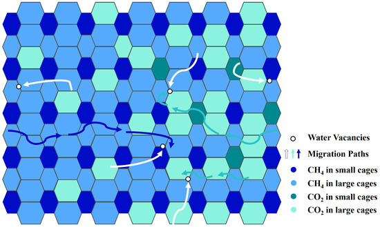
Figure 3.
Schematic diagram of the migration paths of CO2 and CH4 molecules in the hydrate modified after Salamatin et al. [5].
It should be noted that thermodynamic models are not limited to describing the replacement process without CH4 hydrate dissociation. In fact, they are also frequently used in field-scale simulations of CO2-CH4 hydrate replacement reactions [63]. Some numerical simulators for CH4 hydrate reservoirs include equilibrium model modules [70]. In these models, the heat generated from the formation of CO2 hydrate and the sensible heat of injected CO2 serve as the energy for CH4 hydrate dissociation, while the diffusion of guest molecules in hydrate particles is neglected.
In addition, some other models have been established. The kinetic model was combined with the non-equilibrium thermodynamic model by Wang et al. [71] to simultaneously consider the mechanisms of hydrate dissociation/formation and guest molecule replacement within hydrate crystals. Baig et al. [72] combined non-equilibrium thermodynamics and phase-field theory (PFT) to establish a model to study the process of CO2 injection into a system containing gaseous CH4, a single CH4 hydrate particle, and some water. Tegze et al. [73] developed a PFT model for liquid CO2-CH4 hydrate replacement, further confirming that hydrate conversion is controlled by guest molecule diffusion. The fundamental formula of PFT models can be given as follows:
where , , , , and are the phase field, phase-field mobility, free-energy scale, double-well function, and square gradient term coefficient, respectively. is the difference in free energy between the bulk liquid phase and the solid phase.
Khasanov et al. [74] established a numerical model for injecting liquid CO2 into CH4 hydrate reservoirs based on multiphase media mechanics equations, and the diffusion of CO2 molecules in hydrate particles is ignored. The fundamental formula of this model can be given as follows:
where , , , , and are porosity, density, saturation, velocity, and velocity of the boundary, respectively. The subscripts c, m, hc, and hm are CO2, CH4, CO2 hydrate, and CH4 hydrate, respectively.
Khasanov et al. [75] subsequently established a CO2-CH4 hydrate replacement model. The diffusion of guest molecules in hydrates is considered, and the diffusion coefficients are calculated through a new empirical formula. Hsieh et al. [76] treated the molecular replacement region as a virtual aqueous buffer layer based on the film theory of hydrate dissociation. The CH4 hydrate dissociation flux and CO2 hydrate formation flux are given as follows:
where is the intrinsic dissociation constant and and are the CH4 volumetric molar concentration in equilibrium with hydrate and the molar solubility of CH4, respectively. and are the intrinsic generation rate and replacement rate, respectively. is the volumetric molar concentration of guest molecules at the surface of the hydrate in the liquid. The superscripts C and M are CO2 and CH4, respectively.
The Avrami model and the shrinking core model of the crystallization kinetics were used in the work of Lee et al. [77] and Zhao et al. [78,79] to explain the rapid surface reaction stage and the diffusion-limited stage of CO2-CH4 hydrate replacement, respectively. The parameters in these two models were obtained from experimental results. The fundamental formula of the Avrami model and the shrinking core model are given as follows:
where , , , , and are the hydrate conversion ratio, time, rate constant, Avrami exponent, and radius of particle, respectively. The superscript * represents the start of diffusion through hydrate film.
In summary, each model has its own characteristics. In the kinetic models, CH4 hydrate dissociation and CO2 hydrate formation are calculated separately, and the impact of guest molecule diffusion is always neglected or included in the regression coefficient obtained from experimental data. Non-equilibrium thermodynamic models can explain the mechanism of guest molecule diffusion in hydrates. Equilibrium models can take the interphase heat transfer into account, and the guest molecule diffusion in hydrate particles is neglected. CO2-CH4 hydrate replacement models based on the PFT model take the change of a single hydrate particle in seconds as the research object. A comparison of these models is shown in Table 1. Since the latest research suggested that the CO2-CH4 hydrate replacement mechanism varies according to actual reaction conditions and environments, it is crucial to establish or select models based on actual reaction characteristics.

Table 1.
Comparison of some representative models.
4. Factors Affecting CO2-CH4 Hydrate Replacement
4.1. Impact of Replacement Methods
As mentioned above, there are two basic methods for CO2-CH4 hydrate replacement, as follows: dynamic replacement and soaking replacement. The dominant mechanism of the CO2-CH4 hydrate replacement process varies under different replacement methods.
4.1.1. Soaking Replacement
During the process of soaking replacement, CH4 hydrate is maintained at a low temperature or under high pressure to reduce its dissociation, and CO2 is rapidly injected to saturate the pores in a short time. Then, the inlet and outlet are closed. Finally, the temperature and pressure are adjusted to the replacement conditions. It is generally believed that, in this case, CH4 hydrate does not dissociate or only dissociates rapidly and slightly on the surface, and mixed hydrates are formed. Subsequently, a slow replacement by CO2 controlled by diffusion-limited mass transfer of guest molecules occurs [78]. Thus, CH4 hydrate dissociation can be ignored during soaking replacement, and the study of the guest molecule replacement mechanism is mostly carried out in the soaking process.
Ota et al. [80], Yuan et al. [38], Zhao et al. [79], Zhang et al. [81], and Almenningen et al. [2] all have studied the dominant mechanism of soaking replacement. Lee et al. [77] studied a soaking replacement reaction lasting 120 h through the pressure response during the reaction process. They believed that CO2/CH4 mixed hydrates are formed immediately after CH4 hydrate dissociation. The entire process of replacement can be divided into the following two distinct phases: an initial rapid reaction that occurs on the hydrate surface and a slower diffusion-limited phase at the core of the hydrate. Figure 4 shows a diagram illustrating the two-step replacement reaction modified after Wang et al. [71]. The Avrami model and the shrinking core model were used by Lee et al. to describe the replacement rate evolution in these two phases, respectively. The replacement rates in the above studies ranged from 6.07% to 56.60%
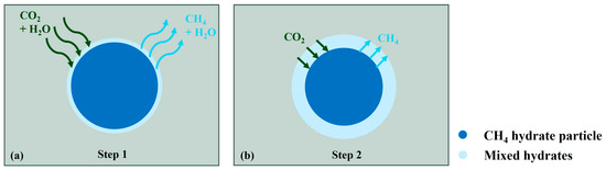
Figure 4.
Schematic diagram of two steps of replacement reaction modified after Wang et al. [71] (a) fast surface reaction stage and (b) diffusion-limited stage.
4.1.2. Dynamic Replacement
During dynamic replacement, CO2 is continuously injected into the porous media containing CH4 hydrate, and the CH4 in the pores is displaced. Wang et al. [82] conducted an experiment on the replacement of CH4 hydrate using a CO2/H2 gas mixture. They concluded that the injection of the mixed gas leads to a decrease in CH4 partial pressure, which causes CH4 hydrate dissociation. Then, the newly formed hydrate layer restricts the interphase mass transfer of gas components, resulting in a decrease in the replacement rate. Khlebnikov et al. [83], Tupsakhare et al. [84], and Chen et al. [20] all conducted experiments combining CO2-CH4 hydrate dynamic replacement with other CH4 hydrate extraction methods. In these combined methods, replacement rates were improved by accelerating the dissociation of CH4 hydrate. Seo et al. [85] carried out experiments on the dynamic replacement and soaking replacement of CH4 hydrate by CO2/N2 gas mixture. The data demonstrated that supplementation of fresh mixed gas can maintain the driving force of the replacement reaction and improve the replacement rate.
For numerical studies, Oldenburg et al. [86] simulated the process of continuously injecting CO2 into depleted natural gas reservoirs to enhance CH4 recovery while simultaneously sequestering CO2. The evolution of pressure, CH4 mass fraction, and CH4 production rate at the production well were analyzed. A sensitivity analysis on CO2-CH4 hydrate replacement was conducted by Huneker [87], and the conclusion that a high recovery efficiency can be obtained at low injection pressures in Type 2 hydrate reservoirs was drawn. White et al. [88] suggested that a lower injection pressure can reduce the secondary formation of hydrates. Janicki et al. [58] believed that CO2 injection changes the thermal conditions of the reservoir, resulting in further dissociation of the CH4 hydrate. The simulation results of the core-scale CO2-CH4 hydrate dynamic replacement by Phirani et al. [57] also showed that a higher CO2 mole fraction in the fluid or the lower injection pressure can cause CH4 hydrate to dissociate during CO2 injection.
From the above studies, it can be seen that in dynamic replacement, the reaction is initially controlled by the hydrate dissociation/formation mechanism. As the reaction progresses, it shifts to being controlled by the guest molecule replacement mechanism. Specifically, the migration of the mobile phases within the pores is caused by CO2 injection, significantly altering the CH4 partial pressure in the fluid, which leads to the depressurization of CH4 hydrate. However, with the formation of CO2 hydrate, CH4 hydrate dissociation is inhibited, and the replacement efficiency decreases.
4.2. Effect of Initial Water
Initial water is usually present in hydrate reservoirs. When CO2 is pumped in, the water migrates through the porous media along with the CO2 and reacts with it to create CO2 hydrate [6]. Castellani et al. [89] experimentally demonstrated that water is essential for CO2 hydrate formation. The research of Zhao et al. [78] indicated that CO2 hydrate formation changes the pressure as the CO2-CH4 hydrate replacement happens. Yuan et al. [38] believed that the presence of initial water helps CO2 hydrate to form, thereby reducing replacement efficiency. Baig et al. [72], on the other hand, argued that the initial water on the surface of CH4 hydrate is conducive to heat transfer, thus promoting the replacement process. The replacement rate is proportional to the amount of water originally around the hydrate particle. Therefore, further research is needed to elucidate the role of initial water in the replacement process.
4.3. Effect of Other Factors
Gambelli et al. [90] and Fan et al. [91] believed that an increase in temperature is beneficial to the improvement of replacement efficiency. However, regarding the effect of pressure, different conclusions have been drawn. Ota et al. [80] thought that an increase in pressure is beneficial to CO2 diffusion, which is helpful for improving the CO2-CH4 hydrate replacement rate. Meng et al. [92], on the other hand, argued that a lower pressure leads to a higher replacement rate because the lower CO2 pressure is conducive to CH4 hydrate dissociation. In the experiment conducted by Zhao et al. [79], the effect of pressure on the replacement rate varied according to the temperature and pressure range of the reaction. In the experiment of Lee et al. [4], pressure had no significant effect on the replacement rate.
Permeability is an important property of hydrate reservoirs, which affects the migration of fluid in pores. There are some studies on the influence of reservoir permeability on the CO2-CH4 hydrate replacement process. Generally, the high permeability facilitates fluid flow [93], and smaller particle sizes (which correspond to lower permeability) result in a larger reaction area for replacement, which is beneficial for the replacement process. But in the study of Ryou et al. [3], the replacement rate was slightly lower in the test with lower permeability. One of the reasons for this result may be that the two sets of experiments used for comparison did not last for the same duration. This may also be due to the fact that permeability affects multiple aspects such as fluid flow and reaction area, so the permeability is not simply positively or negatively correlated with replacement efficiency.
In addition, the distribution of CH4 hydrate in the porous reservoir is uneven. The CO2-CH4 hydrate replacement process is also affected by pore microstructure, CH4 hydrate distribution, wall slip, and so on. The progress in pore-scale research on CO2-CH4 hydrate replacement will be summarized in the next section.
5. Study on Pore-Scale CO2-CH4 Hydrate Replacement
5.1. Pore-Scale Replacement Studies
CO2-CH4 hydrate replacement reactions often occur in porous media, where the contact between the hydrate phase and the fluid phase will be influenced by pore structure, sand composition, hydrate distribution, and so on. Fluid migration and heat and mass transfer will be affected. When initial water is in the pores, the initial water and injected CO2 can form CO2 hydrate that leads to a change in hydrate distribution. In that case, the reservoir permeability and fluid migration are altered. In addition, the surface wettability and adsorption of porous media particles can also affect the replacement process. Hence, delving into the CO2-CH4 hydrate replacement mechanism, reaction characteristics, phase distributions, and fluid migration at the pore scale hold substantial importance. However, compared to macro-scale research and molecular research, the pore-scale research on CO2-CH4 hydrate replacement remains insufficient.
The first pore-scale laboratory investigation on CH4 hydrate recovery by CO2 was conducted by Jadhawar et al. [94]. CO2 was injected into a micro glass pore model with CH4 hydrate and excess water in its pores. The gas produced after the experiment was analyzed. The results revealed that the excess water and CO2 dissolved in the water make it harder for CH4 to be released. The CO2 injection and the changes in CH4 hydrate morphology are shown in Figure 5, redrawn from Jadhawar et al. [94].
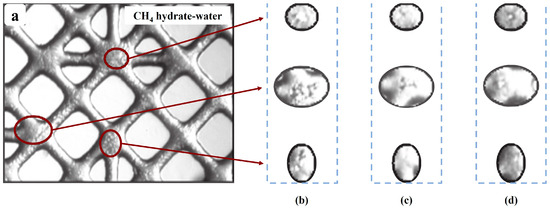
Figure 5.
Images redrawn from Jadhawar et al. [94] for CO2 injection and the changes in CH4 hydrate morphology caused by the injection. (a) CH4 in large cages; (b) 45 h after CO2 injection; (c) 54 h after CO2 injection; (d) 89 h after CO2 injection.
Huang et al. [95] employed microfocus computer tomography along with digital volume correlation (DVC) to study the deformation characteristics of hydrate sediment samples with replacement rates of 0%, 20.86%, 33.24% and 62.59%. Sagittal-plane CT images were utilized to illustrate the microscopic mechanism. Figure 6, modified after Huang et al. [95], illustrates the CT images of the sediment sample containing hydrate with a replacement rate of 20.86%. In this figure, four regions of the sample under various stresses are presented, with the sand particles numbered for observation. The phenomena induced by the increase in strain, such as structural damage (region 1), rotation of sand particles (region 2), the generation and compression of pores (region 3), and the movement of particles (region 4), are depicted. The results show that cement breakdown and partial pore filling are the primary reasons for plastic deformation. CO2-CH4 hydrate replacement alters the cementation structure of the hydrate sediment, resulting in the width of the shear band decreasing from 13.79 to 5.59 times the median particle size.
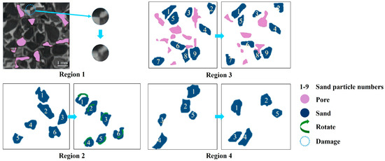
Figure 6.
CT images of the sediment sample containing hydrate with a replacement rate of 20.86% modified after Huang et al. [95].
Microfocus computer tomography was used by Li et al. [96] to study the microstructure evolution of hydrate deposits during the Kr hydrate replacement by gaseous Xe at an initial hydrate saturation of 63% under a pressure of 1 MPa. It was found that temporary local enrichment of the hydrate and blockages was caused by the migration of the released water within the deposits. The flow channel distribution characterized by velocity is shown in Figure 7, modified after Li et al. [96]. The sphericity of hydrate particles was improved and pore connectivity was enhanced after the replacement. Although the existence of blockage temporarily reduced the increase in permeability, the absolute permeability was increased by 225.23%.
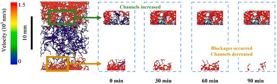
Figure 7.
The image of flow channel distribution characterized by velocity, modified after Li et al. [96].
Obviously, despite the importance of pore-scale research, related work is very deficient, and most of it is qualitative analysis. One of the possible reasons for this is the limitations of experimental methods, which make it difficult to observe pore-scale phenomena and measure relevant parameters. In numerical studies, a major challenge is how to establish an appropriate pore model reflecting pore characteristics. Research on the pore-scale dissociation and formation of hydrates can serve as a useful reference in this regard.
5.2. Pore-Scale Hydrate Dissociation/Formation Studies
Numerical methods were adopted by Fukumoto et al. [18] to examine the pore-scale CH4 hydrate formation. A 3D physical model was established from microscopic CT images of sand grains. The phase field model and classical nucleation theory were used to estimate the distribution of the generated CH4 hydrate in the pores. Finally, the formation process of CH4 hydrate in the pores was successfully simulated. Figure 8 shows the sectional diagram for the distribution of phases during CH4 hydrate formation in pores modified after Fukumoto et al. [18].
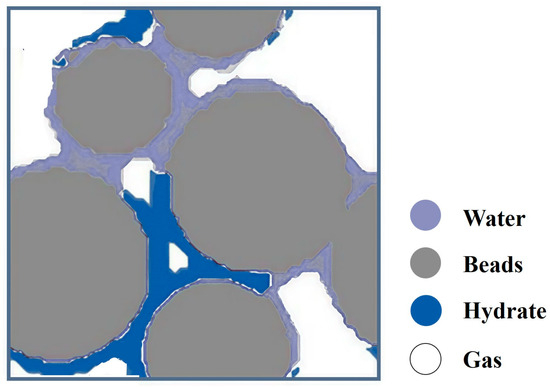
Figure 8.
The sectional diagram for the distribution of phases during CH4 hydrate formation in pores modified after Fukumoto et al. [18].
To reveal the pore-scale dynamic interaction between the structure change in the deposit and the permeability during the hydrate dissociation process, Wang et al. [97] carried out an experiment on Xe hydrate formation and dissociation by the use of X-ray computed tomography (CT). In this experiment, Xe hydrate was generated in spherical quartz and then dissociated by depressurization. The permeability and 3D structure of the hydrate deposit were analyzed during the reaction. The findings indicated that the non-uniformity in the spatial distribution of the hydrate does not alter the power function relationship between permeability and hydrate saturation. Taking hydrate saturation between 16.35% and 25.37% as the cut-off point, the fluid flow resistance at a high hydrate saturation mainly depends on the quantity and size of the pathways, while it depends on the size of the pathways when the hydrate saturation is low. Finally, based on image processing technology, a new relative permeability model was developed. The specific parameters of hydrate saturation were connected to the model. Wang et al. [98] established an experiment on the gas hydrate formation/dissociation in fine-grained quartz sand. The results were analyzed through high-resolution X-ray CT images of the samples during the experimental process. A pore network representing the pore topology was further established to clarify the pore structure changes of the samples. Finally, it was concluded that gas hydrates primarily grow in the pore space through particle cementation. Changes in gas hydrate saturation cause significant variations in pore structure and flow characteristics. The fluid flow is influenced more significantly by the hydrate dissociation compared to the hydrate formation. The damage to pore structure caused by hydrate dissociation may explain the increased frequency percentage of 10–20 μm pores observed in hydrate-bearing samples after the experiment.
Habiburrahman et al. [99] developed a microfluidic technique that can examine the phase transition behaviors of hydrates in pores to investigate the intrapore growth and cross-pore propagation kinetics of hydrates. This study revealed that the pore-filling behavior of the gas hydrate formation is density-dependent: hydrates formed by CH4 and CO2 gas (lower density) fill the pores by partially coating the walls when the hydrate phase equilibrium is reached. Conversely, hydrate formed by the liquid CO2 (higher density) cements the pores rapidly due to volumetric expansion. Thus, the permeability of the porous media is significantly reduced. Fluorescence imaging was used to visualize this pore-filling phenomenon.
Yang et al. [100] established experimental research to study the pore-scale depressurization of hydrates. Microfluidic technology along with high-resolution microscope imaging was utilized in their study. A machine learning algorithm was employed to segment images for the analysis of phase saturation evolution and hydrate dissociation rates. The flow chart of image segmentation for segmenting each phase in the graph is shown in Figure 9, modified after Yang et al. [100]. First, masks representing the pore microstructure were generated from the experimental images. Second, a set of pixels in the original image representing water, gas, and hydrates were manually labeled. The color and texture features of these pixels were extracted by the trained random forest classifier, so predictions were made for the unmarked regions. Finally, with continuous correction of classification errors, image segmentation was achieved. The study revealed that the following two hydrate forms were present in the microfluidic chip: hydrate films and crystals, each exhibiting distinct decomposition characteristics. Hydrate films rapidly dissociated at a rate of 1.12 × 10⁻¹%/s under stable gas–water conditions when the pressure dropped below the hydrate equilibrium pressure. When gas–water migration was considered, the dissociation rate would decrease due to the displacement of the gas in hydrate films by water. Under stable gas–water conditions, the decomposition of hydrate crystals was hindered by limited mass transfer. The decomposition rate was 3.30 × 10⁻³%/s, which is much slower than that of hydrate films. The gas slug flow resulting from pressure reduction has the ability to facilitate the breakdown of hydrates, leading to a rise in the dissociation rate that is over ten times greater than that observed when gas and water are in a stable state.
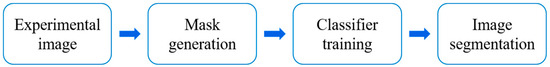
Figure 9.
Flow chart of image segmentation for segmenting each phase in the graph, modified after Yang et al. [100].
In summary, X-ray CT technology, microfluidic chip technology, and pore network models are being increasingly utilized in the study of hydrate formation and dissociation. Through the application of these techniques, porous media models can be constructed effectively and the hydrate behavior within pores can be simulated. Issues such as extracting the topological structural parameters of porous media and visualizing phase distribution during hydrate phase transitions can be successfully addressed. Despite the application of some of these technologies in research on replacing CH4 hydrates with CO2, the focus of the studies remains primarily on qualitative analysis. There is still a lack of research regarding mass transfer, fluid migration, and phase distribution during the CO2-CH4 hydrate replacement process. Since the CO2-CH4 hydrate replacement process involves multiphase and multicomponent systems, distinguishing and identifying each phase may pose a major challenge during experimentation. Therefore, pore-scale simulation studies should not be overlooked. By corroborating experimental observations with simulation results, a more comprehensive understanding of the hydrate behavior within pores can be achieved.
6. Conclusions
CO2-CH4 hydrate replacement involves both the hydrate dissociation/formation mechanism and the guest molecule replacement mechanism within the hydrate. This process includes fluid migration in pores, interphase heat and mass transfer, and is affected by multiple factors such as the replacement method, the presence of initial water, reservoir permeability, temperature and pressure conditions, pore microstructure, hydrate distributions, and so on. It is a complex process involving multiphase and multicomponent systems in porous media. To clarify the replacement mechanisms and boost effectiveness, extensive studies have been carried out, leading to many remarkable results. In this paper, by summarizing the existing research work, the following conclusions are obtained:
(1) CO2-CH4 hydrate replacement is not controlled by a single replacement mechanism. When judging which mechanism a particular replacement process is controlled by, it should be analyzed according to the specific replacement environment. Whether the local temperature and pressure satisfy hydrate phase equilibrium states is crucial to judging whether the CH4 hydrate dissociates. No matter which mechanism dominates the initial replacement reaction, the newly formed hydrate layer will limit the subsequent interfacial mass transfer. Ultimately, the process will be controlled by the mechanism of guest molecule replacement in hydrate crystals, which is the main factor leading to a low replacement rate.
(2) The CO2-CH4 hydrate replacement process is affected by many factors. Understanding how these factors affect the replacement process is essential to finding ways to enhance the replacement process, increase the replacement rate, and overcome the disadvantage of a low replacement efficiency, thereby making the replacement method practically valuable.
Both higher temperatures and lower CO2 partial pressures improve the CO2-CH4 hydrate replacement rate by promoting CH4 hydrate dissociation. Regarding replacement methods, the dominant mechanisms of dynamic replacement and soaking replacement are different. In fact, dynamic replacement can be regarded as a combination of depressurization and guest molecular exchange. The replacement rate can be improved through localized dissociation of CH4 hydrate at the CO2 flow front. However, reservoir deformation and collapse may be caused by excessive dissociation of CH4 hydrate, which would undermine the advantage of the CO2-CH4 hydrate replacement method in maintaining reservoir stability. Therefore, the response of reservoir mechanical stability to the enhanced replacement process is one of the necessary research directions in the future.
The effect of initial water in reservoirs on CO2-CH4 hydrate replacement is seldom studied. Some existing studies suggest that initial water leads to secondary formation and local enrichment of hydrates, resulting in reduced reservoir permeability and obstruction of fluid flow and interphase mass transfer. There is also a view that the presence of water facilitates heat transfer and has positive effects on the replacement reaction. Therefore, the influence mechanism of initial water on CO2 replacement still requires further investigation.
The reaction area and fluid migration are both affected by reservoir permeability. However, current studies generally take uniformly dispersed granular sediments into consideration to calculate the permeability and reaction area. The effect of permeability on replacement processes should be further studied according to the reservoir morphology.
(3) Since CH4 hydrate is mostly found in porous media in nature, studies of the CO2-CH4 hydrate replacement process at the pore scale help to better understand the in situ replacement reaction. However, research on pore-scale CO2-CH4 hydrate replacement is limited and mostly qualitative. Therefore, there is a lack of cognition regarding the influence mechanisms of pore microstructure and hydrate distribution within pores on fluid flow and replacement reaction. In future work, microfluidic chip technology and pore network models can be adopted more extensively to establish pore models that characterize the topological features of hydrate-bearing sediments. X-ray CT technology can be employed to visualize the gas–liquid–solid three-phase distribution within the pores. Experimental setups should be continuously improved and experimental methods should be optimized. Combined with numerical simulations, additional comprehensive investigations on the influence of pore microstructures and wall characteristics on mass transfer, fluid migration, and phase distributions during the pore-scale replacement process can be carried out.
Author Contributions
Conceptualization, funding acquisition, investigation, methodology, software, and writing—original draft, Y.W.; formal analysis, resources, validation, and writing—review and editing, W.L.; data curation, visualization, project administration, X.W.; supervision, B.D. All authors have read and agreed to the published version of the manuscript.
Funding
This research was supported by the Scientific Research Foundation of Hainan Tropical Ocean University (No. RHDRC202315 and No. RHDRC202109).
Data Availability Statement
No new data were created or analyzed in this study.
Conflicts of Interest
The authors declare no conflicts of interest.
References
- Zheng, J.; Chong, Z.R.; Qureshi, M.F.; Linga, P. Carbon dioxide sequestration via gas hydrates: A potential pathway toward decarbonization. Energy Fuels 2020, 34, 10529–10546. [Google Scholar] [CrossRef]
- Almenningen, S.; Graue, A.; Ersland, G. Experimental investigation of critical parameters controlling CH4-CO2 exchange in sedimentary CH4 hydrates. Energy Fuels 2021, 35, 2468–2477. [Google Scholar] [CrossRef]
- Ryou, J.E.; Al-Raoush, R.I.; Alshibli, K.; Lee, J.Y.; Jung, J. Effects of soaking process on CH4-CO2 replacement efficiency for hydrate-bearing sediments. J. Pet. Sci. Eng. 2021, 196, 107772. [Google Scholar] [CrossRef]
- Lee, H.; Seo, Y.; Seo, Y.T.; Moudrakovski, I.L.; Ripmeester, J.A. Recovering methane from solid methane hydrate with carbon dioxide. Angew. Chem.-Int. Ed. 2003, 42, 5048–5051. [Google Scholar] [CrossRef] [PubMed]
- Salamatin, A.N.; Falenty, A.; Kuhs, W.F. Diffusion model for gas replacement in an isostructural CH4-CO2 hydrate system. J. Phys. Chem. C 2017, 121, 17603–17616. [Google Scholar] [CrossRef]
- Wei, W.N.; Li, B.; Gan, Q.; Li, Y. Le Research progress of natural gas hydrate exploitation with CO2 replacement: A eview. Fuel 2022, 312, 122873. [Google Scholar] [CrossRef]
- Zhang, L.; Yang, L.; Wang, J.; Zhao, J.; Dong, H.; Yang, M.; Liu, Y.; Song, Y. Enhanced CH4 recovery and CO2 storage via thermal stimulation in the CH4/CO2 replacement of methane hydrate. Chem. Eng. J. 2017, 308, 40–49. [Google Scholar] [CrossRef]
- Hirohama, S.; Shimoyama, Y.; Wakabayashi, A.; Tatsuta, S.; Nishida, N. Conversion of CH4 hydrate to CO2 hydrate in liquid CO2. J. Chem. Eng. Jpn. 1996, 26, 1014–1020. [Google Scholar] [CrossRef]
- Song, Y.; Wang, S.; Jiang, L.; Zhang, Y.; Yang, M. Hydrate phase equilibrium for CH4-CO2-H2O system in porous media. Can. J. Chem. Eng. 2016, 94, 1592–1598. [Google Scholar] [CrossRef]
- Ding, Y.L.; Wang, H.Q.; Xu, C.G.; Li, X.S. The effect of CO2 partial pressure on CH4 recovery in CH4-CO2 swap with simulated IGCC syngas. Energies 2020, 13, 1017. [Google Scholar] [CrossRef]
- Kossel, E.; Bigalke, N.K.; Deusner, C.; Haeckel, M. Microscale processes and dynamics during CH4-CO2 guest-molecule exchange in gas hydrates. Energies 2021, 14, 1763. [Google Scholar] [CrossRef]
- Liu, W.; Luo, T.; Li, Y.; Song, Y.; Zhu, Y.; Liu, Y.; Zhao, J.; Wu, Z.; Xu, X. Experimental study on the mechanical properties of sediments containing CH4 and CO2 hydrate mixtures. J. Nat. Gas. Sci. Eng. 2016, 32, 20–27. [Google Scholar] [CrossRef]
- Adisasmito, S.; Frank, R.J.; Sloan, E.D. Hydrates of carbon dioxide and methane mixtures. J. Chem. Eng. Data 1991, 36, 68–71. [Google Scholar] [CrossRef]
- Anderson, G.K. Enthalpy of dissociation and hydration number of methane hydrate from the Clapeyron equation. J. Chem. Thermodyn. 2004, 36, 1119–1127. [Google Scholar] [CrossRef]
- Xu, C.G.; Yan, R.; Fu, J.; Zhang, S.H.; Yan, K.F.; Chen, Z.Y.; Xia, Z.M.; Li, X. Sen Insight into micro-mechanism of hydrate-based methane recovery and carbon dioxide capture from methane-carbon dioxide gas mixtures with thermal characterization. Appl. Energy 2019, 239, 57–69. [Google Scholar] [CrossRef]
- Gray, N.D.; Sherry, A.; Larter, S.R.; Erdmann, M.; Leyris, J.; Liengen, T.; Beeder, J.; Head, I.M. Biogenic methane production in formation waters from a large gas field in the North Sea. Extremophiles 2009, 13, 511–519. [Google Scholar] [CrossRef]
- Davies, S.R.; Boxall, J.A.; Dieker, L.E.; Sum, A.K.; Koh, C.A.; Sloan, E.D.; Creek, J.L.; Xu, Z.G. Predicting hydrate plug formation in oil-dominated flowlines. J. Pet. Sci. Eng. 2010, 72, 302–309. [Google Scholar] [CrossRef]
- Fukumoto, A.; Kamada, K.; Sato, T.; Oyama, H.; Torii, H.; Kiyono, F.; Nagao, J.; Temma, N.; Narita, H. Numerical simulation of pore-scale formation of methane hydrate in the sand sediment using the phase-field model. J. Nat. Gas. Sci. Eng. 2018, 50, 269–281. [Google Scholar] [CrossRef]
- Li, Q.; Zhou, S.; Zhao, J.; Song, Y.; Zhu, J. Research status and prospects of natural gas hydrate exploitation technology. Chin. J. Eng. Sci. 2022, 24, 214. [Google Scholar] [CrossRef]
- Chen, Y.; Gao, Y.; Chen, L.; Wang, X.; Liu, K.; Sun, B. Experimental investigation of the behavior of methane gas hydrates during depressurization-assisted CO2 replacement. J. Nat. Gas. Sci. Eng. 2019, 61, 284–292. [Google Scholar] [CrossRef]
- Yin, Z.; Linga, P. Methane hydrates: A future clean energy resource. Chin. J. Chem. Eng. 2019, 27, 2026–2036. [Google Scholar] [CrossRef]
- Yuan, Q.; Sun, C.Y.; Yang, X.; Ma, P.C.; Ma, Z.W.; Li, Q.P.; Chen, G.J. Gas production from methane-hydrate-bearing sands by ethylene glycol injection using a three-dimensional reactor. Energy Fuels 2011, 25, 3108–3115. [Google Scholar] [CrossRef]
- Goel, N. In situ methane hydrate dissociation with carbon dioxide sequestration: Current knowledge and issues. J. Pet. Sci. Eng. 2006, 51, 169–184. [Google Scholar] [CrossRef]
- Ersland, G.; Husebø, J.; Graue, A.; Kvamme, B. Transport and storage of CO2 in natural gas hydrate reservoirs. Energy Procedia 2009, 1, 3477–3484. [Google Scholar] [CrossRef]
- Tupsakhare, S.S.; Castaldi, M.J. Efficiency enhancements in methane recovery from natural gas hydrates using injection of CO2/N2 gas mixture simulating in-situ combustion. Appl. Energy 2019, 236, 825–836. [Google Scholar] [CrossRef]
- Boswell, R.; Schoderbek, D.; Collett, T.S.; Ohtsuki, S.; White, M.; Anderson, B.J. The Iġnik Sikumi field experiment, Alaska North Slope: Design, operations, and implications for CO2-CH4 exchange in gas hydrate reservoirs. Energy Fuels 2017, 31, 140–153. [Google Scholar] [CrossRef]
- Ebinuma, T. Method for Dumping and Disposing of Carbon Dioxide Gas and Apparatus Therefore. U.S. Patent 5261490A, 16 November 1993. [Google Scholar]
- Deusner, C.; Bigalke, N.; Kossel, E.; Haeckel, M. Methane production from gas hydrate deposits through injection of supercritical CO2. Energies 2012, 5, 2112–2140. [Google Scholar] [CrossRef]
- Yoon, J.H.; Kawamura, T.; Yamamoto, Y.; Komai, T. Transformation of methane hydrate to carbon dioxide hydrate: In situ Raman spectroscopic observations. J. Phys. Chem. A 2004, 108, 5057–5059. [Google Scholar] [CrossRef]
- Ota, M.; Abe, Y.; Watanabe, M.; Smith, R.L.; Inomata, H. Methane recovery from methane hydrate using pressurized CO2. Fluid. Phase Equilibria 2005, 228–229, 553–559. [Google Scholar] [CrossRef]
- Xu, C.G.; Cai, J.; Yu, Y.S.; Yan, K.F.; Li, X. Sen Effect of pressure on methane recovery from natural gas hydrates by methane-carbon dioxide replacement. Appl. Energy 2018, 217, 527–536. [Google Scholar] [CrossRef]
- Salamatin, A.N.; Falenty, A.; Hansen, T.C.; Kuhs, W.F. Guest migration revealed in CO2 clathrate hydrates. Energy Fuels 2015, 29, 5681–5691. [Google Scholar] [CrossRef]
- Iwai, Y.; Nakamura, H.; Hirata, M. Molecular dynamics simulation of replacement of methane hydrate with carbon dioxide. Mol. Simul. 2012, 38, 481–490. [Google Scholar] [CrossRef]
- Liu, B.; Pan, H.; Wang, X.; Li, F.; Sun, C.; Chen, G. Evaluation of different CH4-CO2 replacement processes in hydrate-bearing sediments by measuring P-wave velocity. Energies 2013, 6, 6242–6254. [Google Scholar] [CrossRef]
- Dec, S.F. Surface transformation of methane-ethane sI and sII clathrate hydrates. J. Phys. Chem. C 2012, 116, 9660–9665. [Google Scholar] [CrossRef]
- Kvamme, B.; Qasim, M.; Baig, K.; Kivelä, P.H.; Bauman, J. Hydrate phase transition kinetics from Phase Field Theory with implicit hydrodynamics and heat transport. Int. J. Greenh. Gas. Control 2014, 29, 263–278. [Google Scholar] [CrossRef]
- Ota, M.; Morohashi, K.; Abe, Y.; Watanabe, M.; Lee Smith, R.; Inomata, H. Replacement of CH4 in the hydrate by use of liquid CO2. Energy Convers. Manag. 2005, 46, 1680–1691. [Google Scholar] [CrossRef]
- Yuan, Q.; Sun, C.Y.; Yang, X.; Ma, P.C.; Ma, Z.W.; Liu, B.; Ma, Q.L.; Yang, L.Y.; Chen, G.J. Recovery of methane from hydrate reservoir with gaseous carbon dioxide using a three-dimensional middle-size reactor. Energy 2012, 40, 47–58. [Google Scholar] [CrossRef]
- Xu, C.G.; Cai, J.; Yu, Y.S.; Chen, Z.Y.; Li, X. Sen Research on micro-mechanism and efficiency of CH4 exploitation via CH4-CO2 replacement from natural gas hydrates. Fuel 2018, 216, 255–265. [Google Scholar] [CrossRef]
- Baldwin, B.A.; Stevens, J.; Howard, J.J.; Graue, A.; Kvamme, B.; Aspenes, E.; Ersland, G.; Husebø, J.; Zornes, D.R. Using magnetic resonance imaging to monitor CH4 hydrate formation and spontaneous conversion of CH4 hydrate to CO2 hydrate in porous media. Magn. Reson. Imaging 2009, 27, 720–726. [Google Scholar] [CrossRef]
- Lee, S.; Lee, Y.; Lee, J.; Lee, H.; Seo, Y. Experimental verification of methane-carbon dioxide replacement in natural gas hydrates using a differential scanning calorimeter. Environ. Sci. Technol. 2013, 47, 13184–13190. [Google Scholar] [CrossRef] [PubMed]
- Tung, Y.T.; Chen, L.J.; Chen, Y.P.; Lin, S.T. In situ methane recovery and carbon dioxide sequestration in methane hydrates: A molecular dynamics simulation study. J. Phys. Chem. B 2011, 115, 15295–15302. [Google Scholar] [CrossRef]
- Qi, Y.; Ota, M.; Zhang, H. Molecular dynamics simulation of replacement of CH4 in hydrate with CO2. Energy Convers. Manag. 2011, 52, 2682–2687. [Google Scholar] [CrossRef]
- Liang, S.; Liang, D.; Wu, N.; Yi, L.; Hu, G. Molecular mechanisms of gas diffusion in CO2 hydrates. J. Phys. Chem. C 2016, 120, 16298–16304. [Google Scholar] [CrossRef]
- Peters, B.; Zimmermann, N.E.R.; Beckham, G.T.; Tester, J.W.; Trout, B.L. Path sampling calculation of methane diffusivity in natural gas hydrates from a water-vacancy assisted mechanism. J. Am. Chem. Soc. 2008, 130, 17342–17350. [Google Scholar] [CrossRef] [PubMed]
- Buch, V.; Devlin, J.P.; Monreal, I.A.; Jagoda-Cwiklik, B.; Uras-Aytemiz, N.; Cwiklik, L. Clathrate hydrates with hydrogen-bonding guests. Phys. Chem. Chem. Phys. 2009, 11, 10245–10265. [Google Scholar] [CrossRef]
- Wu, G.; Tian, L.; Chen, D.; Niu, M.; Ji, H. CO2 and CH4 hydrates: Replacement or cogrowth? J. Phys. Chem. C 2019, 123, 13401–13409. [Google Scholar] [CrossRef]
- Shagapov, V.S.; Khasanov, M.K.; Musakaev, N.G.; Duong, N.H. Theoretical research of the gas hydrate deposits development using the injection of carbon dioxide. Int. J. Heat. Mass. Transf. 2017, 107, 347–357. [Google Scholar] [CrossRef]
- Kim, H.C.; Bishnoi, P.R.; Heidemann, R.A.; Rizvi, S.S.H. Kinetics of methane hydrate decomposition. Chem. Eng. Sci. 1987, 42, 1645–1653. [Google Scholar] [CrossRef]
- Englezos, P.; Kalogerakis, N.; Dholabhai, P.D.; Bishnoi, P.R. Kinetics of formation of methane hydrates and gas. Chem. Eng. Sci. 1987, 42, 2647–2658. [Google Scholar] [CrossRef]
- Masuda, Y.; Kurihara, M.; Ochuchi, H.; Sato, T. A field-scale simulation study on gas productivity of formations containing gas hydrates. In Proceedings of the 4th International Conference on Gas Hydrates, Yokohama, Japan, 19–23 May 2002; pp. 40–46. [Google Scholar]
- Zhao, J.F.; Ye, C.C.; Song, Y.C.; Liu, W.G.; Cheng, C.X.; Liu, Y.; Zhang, Y.; Wang, D.Y.; Ruan, X.K. Numerical simulation and analysis of water phase effect on methane hydrate dissociation by depressurization. Ind. Eng. Chem. Res. 2012, 51, 3108–3118. [Google Scholar] [CrossRef]
- Clarke, M.; Bishnoi, P.R. Determination of the activation energy and intrinsic rate constant of methane gas hydrate decomposition. Can. J. Chem. Eng. 2001, 79, 143–147. [Google Scholar] [CrossRef]
- Chun, M.K.; Lee, H. Kinetics of formation of carbon dioxide clathrate hydrates. Korean J. Chem. Eng. 1996, 13, 620–626. [Google Scholar] [CrossRef]
- Clarke, M.A.; Bishnoi, P.R. Determination of the intrinsic kinetics of CO2 gas hydrate formation using in situ particle size analysis. Chem. Eng. Sci. 2005, 60, 695–709. [Google Scholar]
- Yousif, M.H.; Sloan, E.D. Experimental investigation of hydrate formation and dissociation in consolidated porous media. SPE Reserv. Eng. 1991, 6, 69–76. [Google Scholar] [CrossRef]
- Phirani, J.; Mohanty, K.K. Kinetic simulation of CO2 flooding of methane hydrates. Proc.-SPE Annu. Tech. Conf. Exhib. 2010, 3, 1781–1797. [Google Scholar]
- Janicki, G.; Schlüter, S.; Hennig, T.; Lyko, H.; Deerberg, G. Simulation of methane recovery from gas hydrates combined with storing carbon dioxide as hydrates. J. Geol. Res. 2011, 2011, 1–15. [Google Scholar] [CrossRef]
- Gharasoo, M.; Babaei, M.; Haeckel, M. Simulating the chemical kinetics of CO2-methane exchange in hydrate. J. Nat. Gas. Sci. Eng. 2019, 62, 330–339. [Google Scholar] [CrossRef]
- White, M.D.; McGrail, B.P. Numerical simulation of methane hydrate production from geologic formations via carbon dioxide injection. In Proceedings of the Offshore Technology Conference, Houston, TX, USA, 5–8 May 2008. [Google Scholar]
- Yonkofski, C.M.R.; Horner, J.A.; White, M.D. Experimental and numerical investigation of hydrate-guest molecule exchange kinetics. J. Nat. Gas Sci. Eng. 2016, 35, 1480–1489. [Google Scholar] [CrossRef]
- Liu, Y.; Hou, J.; Zhao, H.; Liu, X.; Xia, Z. A method to recover natural gas hydrates with geothermal energy conveyed by CO2. Energy 2018, 144, 265–278. [Google Scholar] [CrossRef]
- Sridhara, P.; Anderson, B.J.; Garapati, N.; Seol, Y.; Myshakin, E.M. Novel technological approach to enhance methane recovery from Class 2 hydrate deposits by employing CO2 injection. Energy Fuels 2018, 32, 2949–2961. [Google Scholar] [CrossRef]
- Ohgaki, K.; Takano, K.; Sangawa, H.; Matsubara, T.; Nakano, S. Methane exploitation by carbon dioxide from gas hydrates phase equilibria for CO2-CH4 mixed hydrate system. J. Chem. Eng. Jpn. 1996, 29, 478–483. [Google Scholar] [CrossRef]
- Zhu, T.; McGrail, B.P.; Kulkarni, A.S.; White, M.D.; Phale, H.; Ogbe, D. Development of a thermodynamic model and reservoir simulator for the CH4, CO2, and CH4-CO2 gas hydrate system. In Proceedings of the SPE Western Regional Meeting, Irvine, CA, USA, 30 March–1 April 2005; pp. 533–540. [Google Scholar]
- Schicks, J.M.; Luzi, M.; Beeskow-Strauch, B. The conversion process of hydrocarbon hydrates into CO2 hydrates and vice versa: Thermodynamic considerations. J. Phys. Chem. A 2011, 115, 13324–13331. [Google Scholar] [CrossRef]
- Zhou, X.; Lin, F.; Liang, D. Multiscale analysis on CH4-CO2 swapping phenomenon occurred in hydrates. J. Phys. Chem. C 2016, 120, 25668–25677. [Google Scholar] [CrossRef]
- Zhou, X.; Li, D.; Zhang, S.; Liang, D. Swapping methane with carbon dioxide in spherical hydrate pellets. Energy 2017, 140, 136–143. [Google Scholar] [CrossRef]
- Falenty, A.; Qin, J.; Salamatin, A.N.; Yang, L.; Kuhs, W.F. Fluid composition and kinetics of the in situ replacement in CH4-CO2 hydrate system. J. Phys. Chem. C 2016, 120, 27159–27172. [Google Scholar] [CrossRef]
- Chibura, P.E.; Zhang, W.; Luo, A.; Wang, J. A review on gas hydrate production feasibility for permafrost and marine hydrates. J. Nat. Gas. Sci. Eng. 2022, 100, 104441. [Google Scholar] [CrossRef]
- Wang, Y.; Dong, B.; Zhang, L.; Chen, C.; Li, W.; Song, Y.; Liu, Y. Influences of diffusion-limited transport in the crystals and initial water on the gaseous CO2 dynamic replacement in CH4 hydrate. J. Nat. Gas. Sci. Eng. 2022, 106, 104741. [Google Scholar] [CrossRef]
- Baig, K.; Kvamme, B.; Kuznetsova, T.; Bauman, J. Impact of water film thickness on kinetic rate of mixed hydrate formation during injection of CO2 into CH4 hydrate. Aiche J. 2015, 61, 3944–3957. [Google Scholar] [CrossRef]
- Tegze, G.; Gránásy, L.; Kvamme, B. Phase field modeling of CH4 hydrate conversion into CO2 hydrate in the presence of liquid CO2. Phys. Chem. Chem. Phys. 2007, 9, 3104–3111. [Google Scholar] [CrossRef]
- Khasanov, M.K.; Stolpovsky, M.V.; Gimaltdinov, I.K. Mathematical model of injection of liquid carbon dioxide in a reservoir saturated with methane and its hydrate. Int. J. Heat Mass Transf. 2019, 132, 529–538. [Google Scholar] [CrossRef]
- Khasanov, M.K.; Rafikova, G.R.; Musakaev, N.G. Mathematical model of carbon dioxide injection into a porous reservoir saturated with methane and its gas hydrate. Energies 2020, 13, 440. [Google Scholar] [CrossRef]
- Hsieh, P.Y.; Sean, W.Y.; Sato, T.; Seo, Y.W. Mesoscale modeling of exploiting methane hydrate by CO2 replacement in homogeneous porous media. Int. J. Heat Mass Transf. 2020, 158, 119741. [Google Scholar]
- Lee, B.R.; Koh, C.A.; Sum, A.K. Quantitative measurement and mechanisms for CH4 production from hydrates with the injection of liquid CO2. Phys. Chem. Chem. Phys. 2014, 16, 14922–14927. [Google Scholar] [CrossRef] [PubMed]
- Zhao, J.; Zhang, L.; Chen, X.; Zhang, Y.; Liu, Y.; Song, Y. Combined replacement and depressurization methane hydrate recovery method. Energy Explor. Exploit. 2016, 34, 129–139. [Google Scholar] [CrossRef]
- Zhao, J.; Zhang, L.; Chen, X.; Fu, Z.; Liu, Y.; Song, Y. Experimental study of conditions for methane hydrate productivity by the CO2 swap method. Energy Fuels 2015, 29, 6887–6895. [Google Scholar] [CrossRef]
- Ota, M.; Saito, T.; Aida, T.; Watanabe, M.; Sato, Y.; Smith, R.L.; Inomata, H. Macro and microscopic CH4-CO2 replacement in CH4 hydrate under pressurized CO2. AIChE J. 2007, 53, 2715–2721. [Google Scholar] [CrossRef]
- Zhang, Y.; Xiong, L.J.; Li, X.S.; Chen, Z.Y.; Xu, C.G. Replacement of CH4 in hydrate in porous sediments with liquid CO2 injection. Chem. Eng. Technol. 2014, 37, 2022–2029. [Google Scholar] [CrossRef]
- Wang, X.H.; Sun, Y.F.; Wang, Y.F.; Li, N.; Sun, C.Y.; Chen, G.J.; Liu, B.; Yang, L.Y. Gas production from hydrates by CH4-CO2/H2 replacement. Appl. Energy 2017, 188, 305–314. [Google Scholar]
- Khlebnikov, V.N.; Antonov, S.V.; Mishin, A.S.; Bakulin, D.A.; Khamidullina, I.V.; Liang, M.; Vinokurov, V.A.; Gushchin, P.A. A new method for the replacement of CH4 with CO2 in natural gas hydrate production. Nat. Gas Ind. 2016, 36, 40–47. [Google Scholar] [CrossRef]
- Tupsakhare, S.S.; Fitzgerald, G.C.; Castaldi, M.J. Thermally assisted dissociation of methane hydrates and the impact of CO2 injection. Ind. Eng. Chem. Res. 2016, 55, 10465–10476. [Google Scholar] [CrossRef]
- Seo, Y.J.; Kim, D.; Koh, D.Y.; Lee, J.Y.; Ahn, T.; Kim, S.J.; Lee, J.; Lee, H. Soaking process for the enhanced methane recovery of gas hydrates via CO2/N2 gas injection. Energy Fuels 2015, 29, 8143–8150. [Google Scholar] [CrossRef]
- Oldenburg, C.M.; Pruess, K.; Benson, S.M. Process modeling of CO2 injection into natural gas reservoirs for carbon sequestration and enhanced gas recovery. Energy Fuels 2001, 15, 293–298. [Google Scholar] [CrossRef]
- Huneker, R.H. Natural Gas Production and CO2 Sequestration in a Class 2 Hydrate Accumulation: A Numerical Simulation Study; Delft University of Technology: Delft, The Netherlands, 2010. [Google Scholar]
- White, M.D.; Wurstner, S.K.; McGrail, B.P. Numerical studies of methane production from Class 1 gas hydrate accumulations enhanced with carbon dioxide injection. Mar. Pet. Geol. 2011, 28, 546–560. [Google Scholar] [CrossRef]
- Castellani, B.; Rossetti, G.; Tupsakhare, S.; Rossi, F.; Nicolini, A.; Castaldi, M.J. Simulation of CO2 storage and methane gas production from gas hydrates in a large scale laboratory reactor. J. Pet. Sci. Eng. 2016, 147, 515–527. [Google Scholar] [CrossRef]
- Gambelli, A.M.; Rossi, F. Natural gas hydrates: Comparison between two different applications of thermal stimulation for performing CO2 replacement. Energy 2019, 172, 423–434. [Google Scholar] [CrossRef]
- Fan, S.; Wang, X.; Wang, Y.; Lang, X. Recovering methane from quartz sand-bearing hydrate with gaseous CO2. J. Energy Chem. 2017, 26, 655–659. [Google Scholar] [CrossRef]
- Shi, M.; Woodley, J.M.; Von Solms, N. An experimental study on improved production performance by depressurization combined with CO2-enriched air injection. Energy Fuels 2020, 34, 7329–7339. [Google Scholar] [CrossRef]
- Li, G.; Wu, D.M.; Li, X.S.; Lv, Q.N.; Li, C.; Zhang, Y. Experimental measurement and mathematical model of permeability with methane hydrate in quartz sands. Appl. Energy 2017, 202, 282–292. [Google Scholar] [CrossRef]
- Jadhawar, P.; Mohammadi, A.H.; Yang, J.; Tohidi, B. Subsurface carbon dioxide Storage through clathrate hydrate formation. Adv. Geol. Storage Carbon. Dioxide 2006, 65, 111–126. [Google Scholar]
- Huang, L.; Wu, P.; Wang, Y.; Song, Y.; Li, Y. Pore-scale deformation characteristics of hydrate-bearing sediments with gas replacement. Sci. Total Environ. 2024, 954, 176464. [Google Scholar]
- Li, Y.; Huang, L.; Wu, P.; Wang, Y.; Liu, T.; Wang, H.; Song, Y. Investigation on multi-parameter of hydrate-bearing synthetic sediment during hydrate replacement process: A in-situ X-Ray computed tomography study. Sci. Total Environ. 2024, 929, 172621. [Google Scholar] [CrossRef] [PubMed]
- Wang, H.; Li, Y.; Huang, L.; Liu, T.; Liu, W.; Wu, P.; Song, Y. A pore-scale study on microstructure and permeability evolution of hydrate-bearing sediment during dissociation by depressurization. Fuel 2024, 358, 130124. [Google Scholar] [CrossRef]
- Wang, D.; Wang, C.; Li, C.; Liu, C.; Lu, H.; Wu, N.; Hu, G.; Liu, L.; Meng, Q. Effect of gas hydrate formation and decomposition on flow properties of fine-grained quartz sand sediments using X-Ray CT based pore network model simulation. Fuel 2018, 226, 516–526. [Google Scholar] [CrossRef]
- Habiburrahman, M.; Yu, W.; Ge, K.; Wang, J.; Sultan, A.S. Pore-filling behaviors and lateral propagation of CH4 and CO2 hydrates forming in microfluidic porous media. Chem. Eng. J. 2025, 519, 162234. [Google Scholar] [CrossRef]
- Yang, J.; Liu, Y.; Xu, Q.; Liu, Z.; Dai, X.; Shi, L.; Luo, K.H. Pore-scale visualization of hydrate dissociation and mass transfer during depressurization using microfluidic experiments. Fuel 2024, 368, 131519. [Google Scholar] [CrossRef]


Disclaimer/Publisher’s Note: The statements, opinions and data contained in all publications are solely those of the individual author(s) and contributor(s) and not of MDPI and/or the editor(s). MDPI and/or the editor(s) disclaim responsibility for any injury to people or property resulting from any ideas, methods, instructions or products referred to in the content. |
© 2025 by the authors. Licensee MDPI, Basel, Switzerland. This article is an open access article distributed under the terms and conditions of the Creative Commons Attribution (CC BY) license (https://creativecommons.org/licenses/by/4.0/).