Communication

A New Method for Calculating Dynamic Reserves of Fault-Controlled Condensate Gas Reservoir

1
School of Petroleum and Natural Gas Engineering, Southwest Petroleum University, Chengdu 610500, China
2
Northwest Oilfield Branch, SINOPEC, Urumqi 830063, China
3
Xinjiang Oilfield Branch, China National Petroleum Corporation, Karamay 834000, China
*
Author to whom correspondence should be addressed.
Energies 2025, 18(20), 5402; https://doi.org/10.3390/en18205402
Submission received: 24 May 2025 / Revised: 31 July 2025 / Accepted: 12 October 2025 / Published: 14 October 2025

Abstract

The SHB fault-controlled condensate gas reservoir is the largest ultra-deep carbonate gas reservoir in China, and the accuracy of dynamic reserve calculation is an important basis for developing the development plan. The fault-controlled condensate gas reservoir has some problems, such as “ultra-deep, ultra-high temperature, supercritical”, strong heterogeneity of reservoir space, and difficulty in obtaining real underground reservoir parameters, which seriously affect the results of dynamic reserve evaluation. Combining the quasi-steady flow equation and the flow resistance of a gas well, a new flow material balance method based on the original apparent formation pressure and daily production data is proposed to effectively calculate the dynamic reserves of a gas reservoir. By comparing the calculation results of various dynamic reserves calculation methods for the SHB condensate gas reservoir, it is proven that this method can effectively calculate the dynamic reserves of gas wells and has important guiding significance for the calculation of dynamic reserves of fault control body condensate gas reservoirs.

1. Introduction

The development of ultra-deep natural gas in China is an important strategic direction for our country and has gradually become the main part of the growth in natural gas production. Such gas fields often have characteristics such as strong reservoir heterogeneity, developed fractures, and complex structures. These factors often limit the correct evaluation of dynamic reserves in the early stage [1].
At present, the calculation methods for dynamic reserves of ultra-deep gas reservoirs are mainly divided into five categories: the classical flowing material balance method, the elastic two-phase method, the unsteady well test analysis method, the traditional production decline analysis method, and the modern production decline analysis method [2,3,4,5,6]. When calculating the dynamic reserves of special gas reservoirs, each method often ignores the changes of some reservoir parameters during the production process (such as the compression coefficient and viscosity of high-pressure natural gas) [7], or its accuracy depends on the degree of gas reservoir exploitation [8], resulting in slightly different calculations of the dynamic reserves of the same gas reservoir. A more common method is to use the flowing material balance method, combined with the deliverability equation, to transform the material balance equation into a way of using flowing pressure data to obtain the dynamic reserves of the gas reservoir. However, this method is only applicable to conventional gas reservoirs where the gas well is located in the center of a square drainage area [9,10,11,12].
The fault-controlled condensate gas reservoir is controlled by strike-slip faults. It develops in a long-strip shape on the plane, has a large effective thickness vertically, and shows an “upright plate” shape as a whole. The effective reservoir space is the cave and fracture system formed by faults. Under the control of stress, it shows obvious directionality, and the fluid also has obvious directionality under the constraint of the reservoir space [13,14]. In view of this feature, this paper derives a new method for calculating dynamic reserves based on the flowing material balance method. This method assumes that after the gas well produces at a constant rate and reaches a quasi-steady state, the apparent formation pressure at any point in the formation changes in the same way over time [15]. At the same time, by combining with the flow resistance under quasi-steady flow conditions, it effectively avoids the influence of some formation reserve parameters that are difficult to obtain and their changes. Taking the gas wells in the No. 4 strip of the SHB condensate gas reservoir as an example, comparing the calculation results of multiple reserve calculation methods shows that this method can be effectively applied to the reserve calculation of fault-controlled condensate gas reservoirs.

2. A New Method for Calculating the Dynamic Reserves of Single Wells in Fault-Controlled Gas Reservoirs

The flow pattern in vertical wells of fault-controlled gas reservoirs is linear flow, which is similar to the flow characteristics of horizontal wells in conventional gas reservoirs. On the other hand, the flow pattern in horizontal wells is radial flow, resembling the flow characteristics of vertical wells in conventional gas reservoirs [16]. In addition, the surface crude oil shows the characteristics of condensate oil with “three lows and two highs” (low freezing point, low viscosity, low sulfur content, high initial boiling point, and high wax content). The gas reservoir phase state has the characteristics of “three supers” (ultra-high temperature, ultra-high pressure, supercritical) [17,18,19]. The average initial formation pressure of the gas reservoir is 90.04 MPa, and the average pressure coefficient is 1.17, belonging to an ultra-high-pressure system as a whole. Fault-controlled gas reservoirs are distributed along deep and large fault zones, with a wide vertical distribution range of reservoirs. Different from conventional layered gas reservoirs, the real formation pressure during their development cannot be accurately obtained through calculation [20]. Therefore, by using the conversion relationship between formation pressure and bottom-hole flowing pressure under quasi-steady flow in the gas reservoir, the influence of gas reservoir pressure changes during production on the reserve calculation results can be avoided, and a new flowing material balance equation for fault-controlled condensate gas reservoirs can be developed.
According to the conclusion from the research on the theoretical basis of the “flow” material balance method, after a gas well reaches a quasi-steady state at a constant production rate, the apparent formation pressure at any point changes with time in the same manner. Therefore, when drawing the pressure drop funnel curve of a gas well under quasi-steady state conditions, the ordinate should use the apparent formation pressure, as shown in Figure 1.
In the figure, p p w f is the bottom-hole flowing pressure p w f / Z w f , MPa; is the apparent formation pressure p / Z , MPa; and r e is the supply radius, m.
That is, there are parallel quasi-pressure drop funnel curves, and the following relationship is satisfied:
d p pwf d t = d p pR d t = d p ¯ p d t = T f p sc T sc Z sc q sc r e 2 π h φ
In the formula, dpwf is the change amount of bottom-hole pressure per unit time, MPa; dppR is the change amount of bottom—hole pressure per unit time, MPa; d p ¯ p is the change in formation pressure per unit time, MPa; Tf is the formation temperature, K; Tsc is the temperature under standard surface conditions, K; Zsc is the gas deviation factor; H is the reservoir thickness, m; psc is the formation pressure, MPa; qsc is the production volume under standard surface conditions, 104 m3; φ is the porosity, expressed as a decimal.
For a gas reservoir with a closed outer boundary, ignoring the expansibility of the rock and the connate water, there is a material balance equation:
p R Z R = p i Z i 1 G p G = p i Z i p i Z i G p G
In the formula, pi is the original formation pressure, MPa; pR is the formation pressure, MPa; ZR is the deviation factor of natural gas; Zi is the deviation factor of natural gas under original conditions; Gp is the cumulative production of natural gas, 104 m3; G is the dynamic reserves, 104 m3.
Equations (1) and (2) are solved simultaneously:
p ¯ R Z ¯ R p wf Z wf p R Z R p wf Z wf = C = q sc b pss
bpss—The coefficient under the condition of quasi-steady state flow. MPa·d/m3—Its physical meaning is the flow resistance under the quasi-steady state flow conditions in the productivity equation [16].
In practice, the calculation of the flow resistance coefficient is consistent with the calculation formula for conventional gas reservoirs. For horizontal wells, the reservoir thickness h in the conventional equation is corrected to the horizontal section length L of the fault-controlled horizontal well; for vertical wells, the reservoir thickness h in the conventional equation is corrected to the flow width b of the linear flow in the fault-controlled gas reservoir.
In this way, combined with the material balance equation, we can obtain the following:
Δ p pwf = p i Z i p wf Z wf = p i Z i p R Z R + p R Z R p wf Z wf = p i Z i G p G + q sc b pss
Dividing both sides of the equation by Δ p pwf b pss , we can obtain the following:
q sc Δ p pwf = 1 b pss p i Z i 1 G b pss G p Δ p pwf
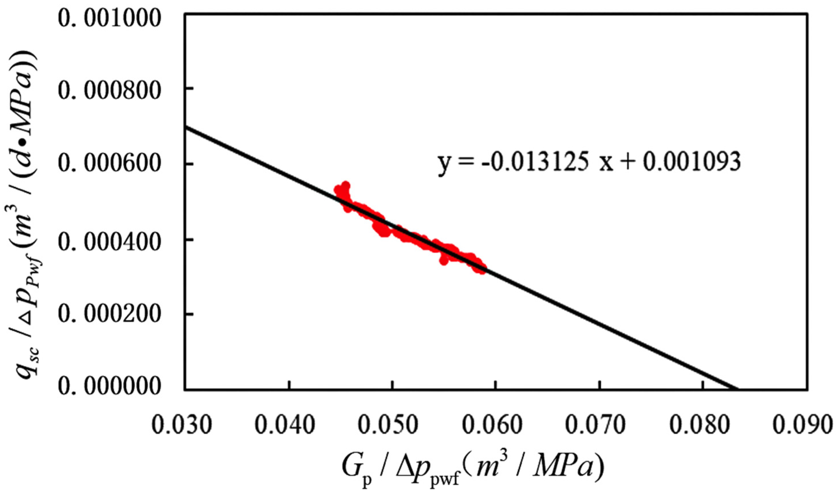
According to the above formula, the relationship between q sc Δ p pwf and G p Δ p pwf can be linearly regressed to obtain the slope value m = p i Z i 1 G b pss and the intercept 1 b pss of the straight line, and thus the dynamic reserve G of the gas reservoir can be obtained:
G = p i / Z i m b pss

3. Actual Application Effects

Taking the gas wells in the No. 4 strip of SHB as an example, the burial depth of the gas reservoir in this area is generally below 7300 m, the original formation pressure is around 90 MPa, and the formation temperature is around 165 °C. It belongs to an ultra-deep, high-temperature, and high-pressure fault-controlled condensate gas reservoir. The reservoir space of the SHB condensate gas reservoir is mainly composed of the cavity of the fault surface formed by fault fragmentation, the pores between breccias, and structural fractures, which have similar production characteristics to the fracture-cavity gas reservoir. The exploration work of the gas reservoir in the second zone of SHB began in 2002. A major breakthrough in oil and gas was achieved in the No. 4 strip in 2017. Later, 20 gas wells were deployed and successively tested to obtain high-yield industrial oil and gas flows, basically realizing the construction of the overall basic well pattern in the No. 4 strip, as shown in Figure 2.
The discovery of the SHB oil and gas field has expanded China’s exploration area in the Tarim Basin. It represents a major breakthrough in oil and gas exploration in new regions, new fields, and new types in the Tarim Basin of China [21].
Taking the SHB4-5H gas well in the No. 4 strip of SHB as an example, according to Formula (5), the values of q sc Δ p pwf and G p Δ p pwf at different times are calculated respectively. Taking q sc Δ p pwf as the ordinate and G p Δ p pwf as the abscissa, through linear regression, the straight-line segment, as well as the slope and intercept of the straight line, are obtained. The relationship of the linear regression is shown in Figure 3.
By performing linear regression to obtain the slope m and the intercept b, and substituting the original apparent formation pressure pi into Formula (6), the dynamic reserve G of the gas well can be obtained, as shown in Table 1.
According to statistical calculations, when the pressure of the SHB4-5H gas well drops to two-thirds, the cumulative gas production is approximately 160 million cubic meters. According to the research results of Sun Hedong, in the early stage of the condensate gas reservoir, the empirical method of gas production per unit cumulative pressure drop can be applied, and the estimated reserve of the SHB4-5H gas well is 400 million cubic meters. It is difficult for the traditional flow material balance method to determine the inflection point of the two-stage curve of the ultra-high-pressure gas reservoir. At the same time, most of the other gas reservoir engineering methods do not consider the deviation coefficient of high-pressure natural gas [22,23,24]. Therefore, the calculation results of the reserve of the SHB4-5H gas well vary, as shown in Table 2.
The calculation results show that the reserve calculation result of the new method for SHB4-5H is 400 million cubic meters, which is close to the average calculation result of 407.5 million cubic meters for SHB4-5H obtained by other reserve calculation methods. It is not difficult to see that the calculation results of the traditional flow material balance method and the gas production curve method are on the high side, the calculation result of the reservoir influence function method is on the low side, and the calculation result of Sun Hedong’s empirical formula method is close to the average value.
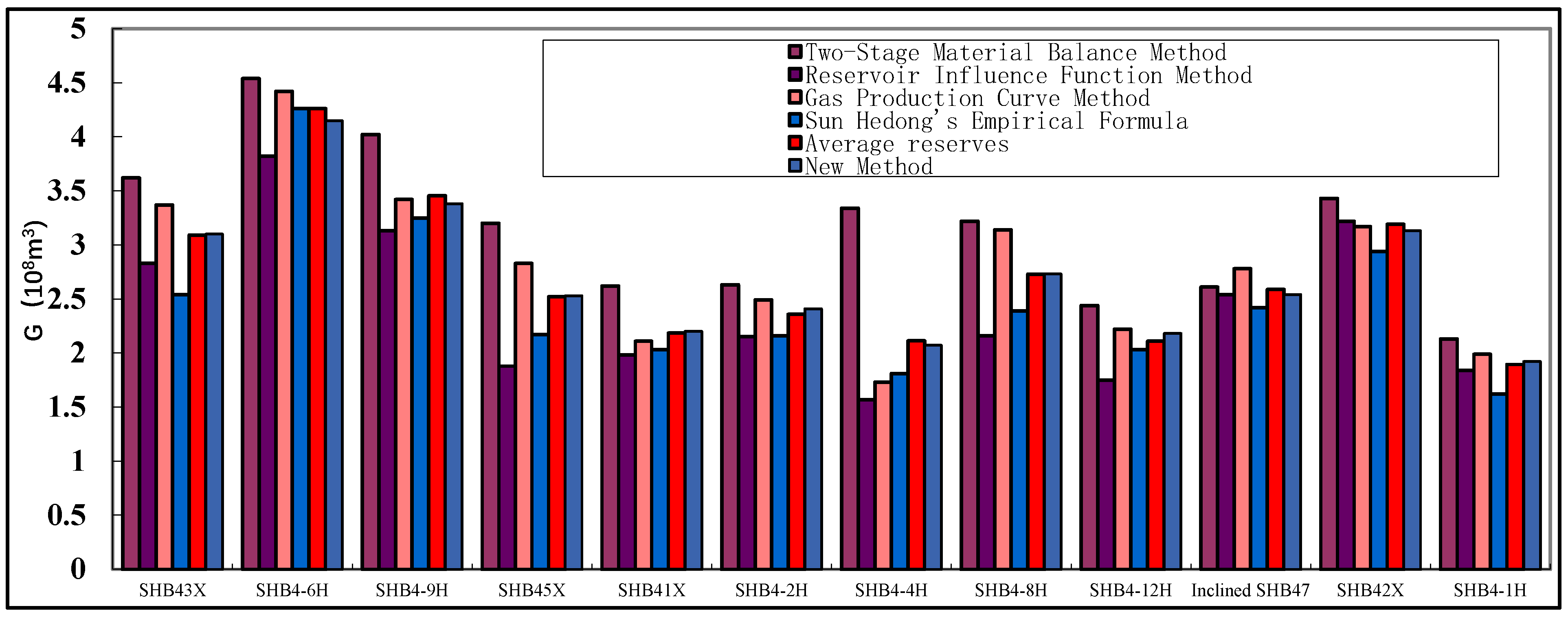
Other gas well dynamic reserves calculation results are shown in Table 3 and Figure 4.
Through the analysis of the data results, for the fault-controlled condensate gas reservoirs with complex underground reservoir spaces, due to the directionality of both their fluids and reservoir spaces, and the characteristics of the gas reservoirs such as a large ground-dew point pressure difference, strong ability to carry heavy oil, and a long single-gas-state time window, the calculation results of the dynamic reserves of such gas reservoirs by traditional gas reservoir engineering methods vary. Generally, the calculation results of the traditional flow material balance method are basically higher than those of other methods, and the calculation results of the reservoir influence function method are lower than those of other methods. In terms of the average value, the new method approaches the average value of other methods. To sum up, it is believed that the newly derived method described above is reliable for calculating the reserves of fault-controlled condensate gas reservoirs.

4. Conclusions

(1) For the fault-controlled condensate gas reservoirs with “vertical plate”-shaped strata and complex fluid properties, the time period when the working system of the gas well remains unchanged and the production is stable is selected. When the gas well reaches a quasi-steady state at a fixed production rate and the apparent pressure change in the reservoir is a constant value, the influence of the pressure change of the gas reservoir during the production process on the reserve calculation result is avoided. The dynamic reserve can be obtained through linear regression based on the original apparent formation pressure and daily production data, and the calculation is simple and easy to implement.
(2) For the fault-controlled condensate gas reservoirs with complex underground reservoir spaces, the calculation results of the dynamic reserves by traditional gas reservoir engineering methods vary. Among them, the calculation results of the traditional flow material balance method are basically higher than those of other methods, and the results of the reservoir influence function method are basically the smallest. The average value of multiple methods approaches the calculation result of the new method.
(3) At present, there is a lack of standards for calculating the reserves of fault-controlled condensate gas reservoirs. Referring to the empirical method of gas production per unit cumulative pressure drop and combining with the calculation average values of multiple reserve calculation methods for the SHB fault-controlled condensate gas reservoir as the basis, it is believed that this method is relatively accurate and can be effectively applied to the calculation of the reserves of fault-controlled condensate gas reservoirs.
(4) The new method takes into account the particularities of fault-controlled bodies and can incorporate the characteristics of fault sealing or limited conductivity. It better conforms to the actual seepage boundaries of fault-controlled bodies, thereby enhancing the pertinence of reserve calculation. Meanwhile, it is also adaptable to the phase changes of condensate gas reservoirs. During the development process of condensate gas reservoirs, oil and gas phase transitions (such as retrograde condensation) will occur due to pressure changes. The new method combines the principle of material balance with phase changes through phase equilibrium equations, which can more accurately reflect the changes in total fluid volume and reduce errors caused by the influence of phase states. In addition, this method is mainly based on dynamic production data (such as production volume and pressure changes) and does not require excessive reliance on static data with limited accuracy (such as porosity and gas saturation distribution). It is particularly suitable for complex structures, such as fault-controlled bodies that are difficult to describe statically, thus improving the practicability of reserve calculation.

Author Contributions

Conceptualization, Q.H. and F.W.; Methodology, Q.H. and F.W.; Formula derivation, F.W. and C.Y.; Verification, Q.H.; Software, H.X. and W.Z.; Formal analysis, W.L. and J.L.; Investigation, F.W. and C.Y.; Data management, H.X., W.Z., W.L. and J.L.; Writing—preparation of original drafts, C.Y. and F.W.; Writing—review and editing, Q.H. and F.W.; Visualization, Q.H.; Supervision, Q.H.; Project management, Q.H.; Funding acquisition, Q.H. All authors have read and agreed to the published version of the manuscript.

Funding

This research received no external funding.

Data Availability Statement

The original contributions presented in the study are included in the article; further inquiries can be directed to the corresponding author.

Acknowledgments

I would like to express my gratitude to Q.H. and C.Y. for providing the methods and formula derivations. I also appreciate H.X., W.Z., J.L. and W.L. for their data support.

Conflicts of Interest

Authors Hong Xiao, Wenxue Zhang, Jie Liu, Wenliang Li were employed by SINOPEC. Cong Yang were employed by China National Petroleum Corporation. The remaining authors declare that the research was conducted in the absence of any commercial or financial relationships that could be construed as a potential conflict of interest.

References

  1. Li, X.Z.; Guo, Z.H.; Hu, Y.; Liu, X.; Wan, Y.; Luo, R.; Sun, Y.; Che, M. Challenges, countermeasures and suggestions for high-quality development of super-deep gas fields in China. Gas Ind. 2020, 40, 75–82. [Google Scholar]
  2. Mattar, L.; McNeil, R. The “flowing” gas material balance. J. Can. Pet. Technol. 1998, 37, 52–55. [Google Scholar] [CrossRef]
  3. Sun, H.; Cao, W.; Li, J.; Jia, W.; Li, Y.; Wu, Y.; Zhu, S.; Fu, X.; Yang, M.; Meng, G. A new method to improve the reliability of dynamic reserves evaluation of ultra-deep and ultra-high pressure gas reservoirs—Practical material balance analysis method. Gas Ind. 2020, 40, 49–56. [Google Scholar]
  4. Chen, Y.Q.; Shi, X.M. Derivation and application of new elastic two-phase method. Reserv. Eval. Dev. 2023, 13, 135–140. [Google Scholar] [CrossRef]
  5. Zhang, Y.Z. Production Decline Analysis Method and Application of Gas Well in Tight Gas Reservoir. Master’s Thesis, China University of Petroleum (Beijing), Beijing, China, 2019. [Google Scholar] [CrossRef]
  6. Feng, D.; Tang, Y.H.; Li, Y.; Li, X.; Li, D.; Jia, H. Study on calculation method of dynamic reserves of continental shale gas in Yan’an area. Unconv. Oil Gas 2023, 10, 27–31+43. [Google Scholar] [CrossRef]
  7. Li, Q.; Guo, P.; Huang, Q.H. Study on dynamic reserves method of gas well. J. Chongqing Univ. Sci. Technol. (Nat. Sci. Ed.) 2008, 34–36. [Google Scholar] [CrossRef]
  8. Mattar, L.; Anderson, D.; Stotts, G. Dynamic material balance: Oil-or gas-in-place without shut-ins. J. Can. Pet. Technol. 2006, 45, 7–10. [Google Scholar] [CrossRef]
  9. You, X.T.; Jia, C.S.; Liu, J.Y.; Liao, X.; Zheng, A.; Li, J. A new production data analysis method of shale gas: Based on flowing material balance theory and considering the complex flow mechanisms of multiple pressure systems. Energy Procedia 2019, 158, 3626–3632. [Google Scholar] [CrossRef]
  10. Han, G.F.; Liu, M.; Li, Q. Flowing material balance method with adsorbed phase volumes for unconventional gas reservoirs. Energy Explor. Exploit. 2019, 38, 519–532. [Google Scholar] [CrossRef]
  11. Xu, Y.M.; Oluwatobi, A.; Hassan, D. A flowing material balance equation for two-phase flowback analysis. J. Pet. Sci. Eng. 2016, 142, 170–185. [Google Scholar] [CrossRef]
  12. He, L.; Mei, H.Y.; Hu, X.R.; Dejam, M.; Kou, Z.; Zhang, M. Advanced flowing material balance to determine original gas in place of shale gas considering adsorption hysteresis. SPE Reserv. Eval. Eng. 2019, 22, 1282–1292. [Google Scholar] [CrossRef]
  13. Sun, Z.; Shi, J.T.; Zhang, T.; Wu, K.; Miao, Y.; Feng, D.; Sun, F.; Han, S.; Wang, S.; Hou, C.; et al. The modified gas-water two phase version flowing material balance equation for low permeability CBM reservoirs. J. Pet. Sci. Eng. 2018, 165, 726–735. [Google Scholar] [CrossRef]
  14. Zhang, C.S.; Han, Z.; Feng, Z.G.; Fan, Z.F.; Xu, A.Z.; He, C.G.; Zhang, D.Y.; Li, J.G.; Wang, F.R.; Ren, J.H.; et al. Calculation method of dissolved gas reinjection reservoir mass balance based on equation of state. Sci. Technol. Eng. 2020, 20, 9851–9855. [Google Scholar]
  15. Huang, Q.H.; Chen, C.; Pi, J.; Wang, F.; Yang, R.; Wu, J. Research on theoretical basis of “flowing” material balance method. Reserv. Eval. Dev. 2015, 5, 30–33+49. [Google Scholar] [CrossRef]
  16. Li, D.M.; Li, H.H.; Zhu, S.Y.; Li, T. Flow material balance method of fault solution reservoir. Lithol. Reserv. 2022, 34, 154–162. [Google Scholar]
  17. Teng, J.W.; Si, X.; Wang, Y.C.H. Exploration, development potential and future of fossil energy in China. Pet. Geophys. Explor. 2021, 60, 1–12. [Google Scholar]
  18. Sun, H.D.; Cao, W.; Zhu, S.B.; Tang, Y.L.; Wu, Y. Challenges, analysis methods and suggestions for dynamic reserves evaluation of ultra-high pressure gas reservoirs. In Proceedings of the the 32nd National Natural Gas Academic Conference (2020), Chongqing, China, 13–14 November 2020; pp. 603–612. [Google Scholar] [CrossRef]
  19. Hu, W.G. Development technology and research direction of fracture-vuggy carbonate reservoir in Tahe Basin. Reserv. Eval. Dev. 2020, 10, 1–10. [Google Scholar] [CrossRef]
  20. Wang, F.P.; Huang, Q.H.; Yang, H.B.; Zhao, C.Z.; Chen, L. Optimization of formation pressure calculation method based on production data. Fault-Block Oil Field 2009, 16, 66–68. [Google Scholar]
  21. Zhang, Y.; Mao, Q.Y.; Li, H.Y.; Li, Z.; Han, J.; Lin, B. Characteristics and practical application of ultra deep fault controlled fracture cave type oil and gas reservoirs in the central part of Shunbei. China Pet. Explor. 2023, 28, 1–13. [Google Scholar]
  22. Deng, H.; Feng, X.; Wang, H.; Hu, S.Q.; He, Y.B. A method for calculating dynamic reserves in the early stage of complex gas reservoir development and its applicability analysis. Gas Ind. 2012, 32, 61–63+123. [Google Scholar]
  23. Liu, R.H. Discussion on calculation method of dynamic reserves in early stage of gas reservoir development. Spec. Oil Gas Reserv. 2012, 19, 69–72+154. [Google Scholar]
  24. Huang, Q.H.; Li, S.L.; Cao, W.J.; Xu, S. Application of reservoir influence function in gas reservoir. Gas Ind. 2003, 106–109+184. [Google Scholar]
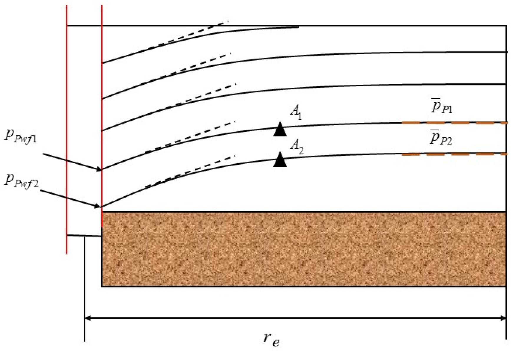
Figure 1. Schematic diagram of the flowing material balance method.
Energies 18 05402 g001
Figure 2. Distribution map of well locations deployed in the plan for fault zone No. 4.
Energies 18 05402 g002
Figure 3. The linear regression straight line of the new flow material balance method for well SHB4-5H.
Energies 18 05402 g003
Figure 4. Calculation results of the dynamic reserves of other gas wells by different gas reservoir engineering methods.
Energies 18 05402 g004
Table 1. Calculation results of parameters of the new method of gas well flow material balance.
Well NumberSlope
m
Intercept
b
Flow Resistance Coefficient
b p s s
Apparent Original Formation Pressure
pi/Zi
Dynamic Reserve
G
SHB4-5H−0.0131250.00109391547.64.0
Table 2. Calculation results of the dynamic reserves of well SHB4-5H by different gas reservoir engineering methods.
Well NumberTwo-Stage Material Balance Method
(100 Million Cubic Meters)
Reservoir Influence Function Method
(100 Million Cubic Meters)
Gas Production Curve Method
(100 Million Cubic Meters)
Sun Hedong’s Empirical Formula
(100 Million Cubic Meters)
New Method
(100 Million Cubic Meters)
SHB4-5H4.323.814.193.984.00
Table 3. Calculation results of the dynamic reserves of other gas wells by different gas reservoir engineering methods.
Well NumberTwo-Stage Material Balance MethodReservoir Influence Function MethodGas Production Curve MethodSun Hedong’s Empirical
Formula
Average
Reserves
New Method
SHB43X3.622.833.372.543.093.10
SHB4-6H4.543.824.424.264.264.15
SHB4-9H4.023.133.423.253.463.38
SHB45X3.201.882.832.172.522.53
SHB41X2.621.982.112.032.192.20
SHB4-2H2.632.152.492.162.362.41
SHB4-4H3.341.571.731.812.112.07
SHB4-8H3.222.163.142.392.732.73
SHB4-12H2.441.752.222.032.112.18
Inclined SHB472.612.542.782.422.592.54
SHB42X3.433.223.172.943.193.13
SHB4-1H2.131.841.991.621.901.92
Disclaimer/Publisher’s Note: The statements, opinions and data contained in all publications are solely those of the individual author(s) and contributor(s) and not of MDPI and/or the editor(s). MDPI and/or the editor(s) disclaim responsibility for any injury to people or property resulting from any ideas, methods, instructions or products referred to in the content.