Abstract
In order to solve the problem of combustion cycle variation in two-stroke aviation kerosene piston engines under idle conditions, experiments were conducted to investigate the influence of intake air temperature on combustion cycle variation and output work. The coefficient of variation of the indicated mean effective pressure was used to characterize combustion cycle variation. The results showed that there is a negative correlation between the engine combustion work and the combustion cycle variation. In the lower range, increasing the intake air temperature has a greater effect on reducing the combustion cycle variation, while in the higher range, the combustion cycle variation has a greater impact on the output work. At the same time, the influence of intake air temperature on the fuel evaporation rate is related to engine speed, and this relationship weakens as the engine speed increases. In the range of 0~40 °C, the higher the intake air temperature, the larger the stable combustion range.
1. Introduction
In the last few years, the number of unmanned aerial vehicles on the market has grown. Among them, low-power two-stroke engines are widely used in small to mid-sized unmanned aerial vehicles due to their high power-to-weight ratio [1]. In terms of fuel selection, compared to gasoline (with its higher vapor pressure and strong volatility), kerosene demonstrates greater safety in storage and usage due to its lower vapor pressure and superior thermal stability. Furthermore, kerosene possesses an energy density comparable to that of gasoline, making it an increasingly ideal fuel for small aviation two-stroke engines; its application is widely recognized and highly regarded in scientific literature [2,3,4]. However, for inlet injection, its heavy oil particles can easily condense into a liquid film after contact with the wall of a cold air duct, and it is difficult to form a uniform combustible mixture; thus, the actual air–fuel ratio is different from the theoretical air–fuel ratio, which leads to the combustion instability of the engine [5]. Therefore, aviation kerosene is not easy to use in two-stroke engines [6].
An increase in the intake air temperature (IAT) can effectively improve fuel atomization and evaporation, make the mixture more uniform, and enhance combustion stability [7]. Many scholars have extensively studied the role of IAT in combustion cycle variation. The indicated mean effective pressure (IMEP) encapsulates detailed pressure fluctuation data and is widely regarded as the most reliable parameter for assessing combustion cycle variation. This parameter has been widely used to quantitatively evaluate combustion cycle variation [8]. Yao et al. used IMEP to study the combustion cycle variation of homogeneous charge compression ignition; they found that with an increase in IMEP, the combustion cycle variation of the engine decreased and the combustion stability decreased [9]. Liu et al. also found that as the distribution range of the IMEP decreased, the combustion cycle variation decreased and the combustion stability was enhanced [10]. Maurya et al. evaluated combustion cycle variation using the coefficient of variation of the indicated mean effective pressure and found that the variation decreased as the IAT rose [11]. In addition, Wang et al. found that combustion cycle variation is particularly influenced by variations in IAT under low-load conditions. With an increase in IAT, decreased and the combustion stability increased [12,13,14]. Compared with the low-load condition, when the two-stroke engine was idle, the throttle was almost closed, the intake pressure was low, the airflow speed was weak, and the diffusion ability was insufficient, resulting in large charge fluctuations. At the same time, the low combustion temperature further deteriorated the combustion, causing a significant increase in engine speed changes [15,16].
IAT leads to combustion cycle variation, which directly affects the engine’s output power. The primary focus of current research is on how variations in IAT influence combustion cycles and power output. To this end, many researchers have carried out relevant studies. Regarding the link between combustion cycle variation and engine output power, some studies suggest that eliminating such a variation can lead to a 10% increase in engine output power without changing the fuel consumption [17]. With regard to the relationship between intake temperature and output power, Chen et al. found that the output power of the engine decreased with an increase in IAT when studying the influence of altitude on the output power of an aviation kerosene two-stroke engine. The reason for this is that a high IAT will lead to a decrease in air density, resulting in insufficient intake [18]. Yu et al. also found that, at a certain altitude, the engine power showed an increasing trend as the IAT decreased [19]. Li et al. found that changing the IAT can improve combustion, accelerate the combustion process, as well as enhance the engine’s effective power and indicated thermal efficiency [20].
The hybrid unmanned aerial vehicle engine is required to maintain idle operation for extended periods at low altitudes [21]. Idle speed, a typical working condition of the engine, accounts for about 25% of the running time and 30% of the fuel, and the combustion cycle varies considerably [22,23]. The low-temperature environment causes difficulties in fuel evaporation, exacerbating combustion cycle variations at idle conditions. Therefore, this study employed the sensitivity coefficient method to establish a quantitative relationship between intake air temperature, combustion cycle variation, and output power; experiments were conducted under idle conditions on a two-stroke engine. Next, the experimental results are discussed, and the impacts of intake air temperature and crankcase temperature on the fuel evaporation rate are analyzed. After operating under different loads, the engine’s crankcase temperature varies. Based on the fuel evaporation rates at these temperature conditions, fuel injection is adjusted to improve fuel economy. Additionally, at different intake air temperatures, reducing combustion cycle variations and enhancing combustion stability at idle conditions becomes significant.
2. Experimental Specifications
2.1. Experimental Setup
This research was carried out on an engine measurement and control platform composed of the following parts: an intake temperature control system, signal acquisition system, exhaust condensation system, dynamometer, and engine. Figure 1 illustrates the layout of the test bench. The aviation kerosene details are shown in Table 1, the engine parameters are provided in Table 2, and the signal acquisition equipment and specifications are shown in Table 3.
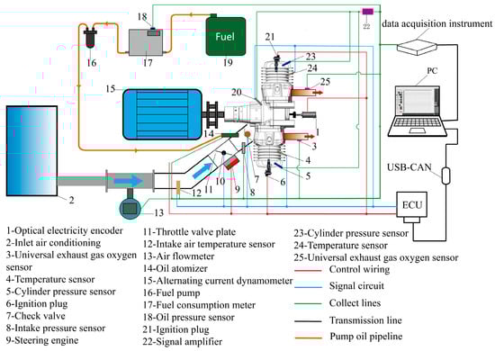
Figure 1.
Measurement and control test platform of the two-stroke aviation kerosene piston engine.

Table 1.
Fuel properties.
Table 2.
Main parameters of the two-stroke aviation kerosene piston engine.
Table 3.
Testing signal acquisition equipment, specifications, and measurement uncertainties.
2.2. Test Conditions
When studying the influence of on combustion cycle variation and output power, the injection pulse width is adjusted under the following conditions, as shown in Table 4, and the engine is kept in an idle condition.
Table 4.
Environmental conditions of engine idling.
When the engine is working, the heat release will lead to an increase in the crankcase temperature . and jointly affect the fuel evaporation rate. The temperature range of the typical working condition of the crankcase is between 40 °C and 120 °C, and the working condition is selected, as shown in Table 5. To investigate the effects of different values on the fuel evaporation rate, the crankcase is heated to the test condition temperature and kept within ±3 °C using a heating device. The dynamometer motors the engine at the specified speed, injecting fuel based on the measured intake airflow and the set air–fuel ratio. The ignition system is deactivated to ensure that the combustible mixture formed by fuel evaporation is not ignited and can be collected at the exhaust end, allowing the engine to operate in a non-combustion state for testing. The exhaust-condensing equipment reduces the temperature of the mixture so that the aviation kerosene in the mixture is liquefied again and collected.
Table 5.
Intake and crankcase temperatures under different speed conditions.
2.3. Evaluation Index and Method
By comparing the collected liquefied fuel mass with the total fuel injection during the test run, the rate under each working condition is calculated. The calculation formula is as follows:
where represents the total mass of fuel injected into the injector, represents the actual collected liquefied fuel mass, and represents the fuel evaporation rate.
The IMEP is closely related to the output power of the engine [23,24]. In this paper, the average IMEP of consecutive combustion cycles is used as the index of combustion output work. To determine how affects the combustion cycle variation rate, in this study, the average IMEP is selected to evaluate the cyclic variation in engine combustion. The calculation formula for the cyclic variation rate is as follows:
where is the mean value of the combustion state parameter IMEP of cycles; is the deviation of IMEP, which is the combustion characteristic quantity of cycles; is the IMEP for each cycle; and is the number of samples. When studying combustion stability, is generally used as the stable combustion boundary [25]. This study aims to clarify the stable combustion range at various inlet temperatures. When the actual measured , the corresponding excess air coefficient is used as the judgment boundary of the stable combustion range.
In order to quantify the influence of on combustion cycle variation, the parameter is defined to represent the increment in the combustion variation rate caused by unit temperature change. The calculation formula is as follows:
where represents the combustion cycle variation rate corresponding to the excess air coefficient and ; the excess air coefficient is defined as the ratio of the actual air–fuel ratio (A/F) to the stoichiometric air–fuel ratio (A/F) stoichiometric. At the same time, in order to eliminate the calculation errors, 0 and are used as the reference benchmarks.
To examine the effect of combustion cycle variation on the IMEP, the parameter is defined to represent the increment in the IMEP caused by the change in the unit combustion cycle variation rate. The calculation formula is as follows:
where represents the IMEP, given and .
To explore the relationship between and the output work, the parameter is defined to represent the increment in IMEP per unit temperature. The specific calculation method is as follows:
where and represents the difference in the IMEP under the same and different .
3. Results
3.1. Influence of Combustion Cyclic Variation on Output Work
Figure 2 shows and at 0 °C. As increases, initially decreases rapidly, then gradually increases, while the engine combustion output power increases initially before decreasing. The maximum combustion output power is observed when reaches its minimum. It is concluded that the engine combustion work is negatively correlated with ; when decreases, the combustion output work increases, and when increases, the combustion output work decreases.
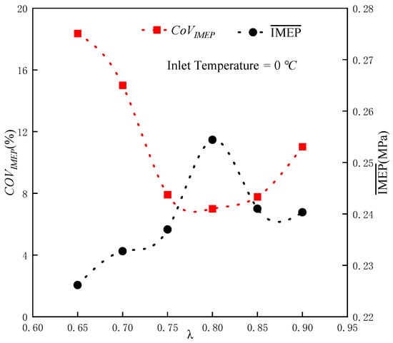
Figure 2.
The relationship between the combustion cycle variation and the output work at an intake air temperature of 0 °C.
3.2. Influence of Inlet Temperature on Output Work
Figure 3 shows the of 50 consecutive combustion cycles at different under conditions of = 0 °C, 20 °C, and 40 °C. The results show that at the same , the increases with an increase in . This is mainly attributed to the rise in and the increased volume of mixed gas involved in combustion. In addition, an increase in makes the mixture distribution more uniform. The difference in the amount and distribution of the mixture between the combustion cycles decreases, resulting in a decrease in and an increase in the combustion work. Under the condition that remains unchanged, the first increases and then decreases with a decrease in .
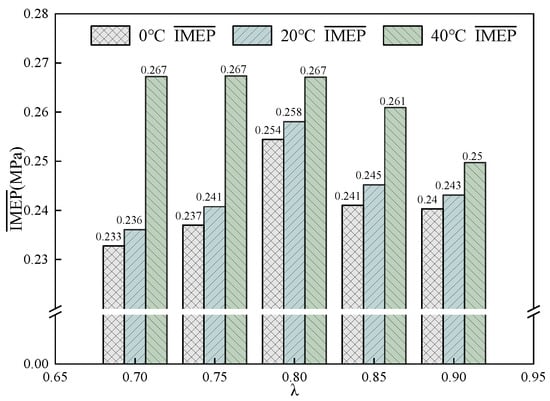
Figure 3.
The average IMEP values at intake temperatures of 0 °C, 20 °C, and 40 °C.
Figure 4 shows the fuel evaporation rate of aviation kerosene at different engine speeds, with = 0 °C, 20 °C, and 40 °C, = 55 °C, 85 °C, and 115 °C. The results show that an increase in can promote . At low speeds, is highly sensitive to . As the speed increases, the sensitivity of to decreases. At the same time, at low speeds, has a strong correlation with speed. As the speed increases, its effect on gradually diminishes. The increase in crankcase temperature promotes fuel evaporation.
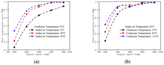
Figure 4.
(a) The fuel evaporation rates of aviation kerosene under different rotational speeds and intake air temperatures at . (b) The fuel evaporation rates of aviation kerosene under different rotational speeds and crankcase temperatures at .
3.3. Relationship Between Intake Air Temperature and Combustion Cycle-to-Cycle Variation Rate and Output Work
Figure 5 shows at 0 °C, 20 °C, and 40 °C. The results show that with an increase in , decreases first, remains stable, and then increases gradually. When the combustion cycle variability is low, it exhibits a stable combustion state.
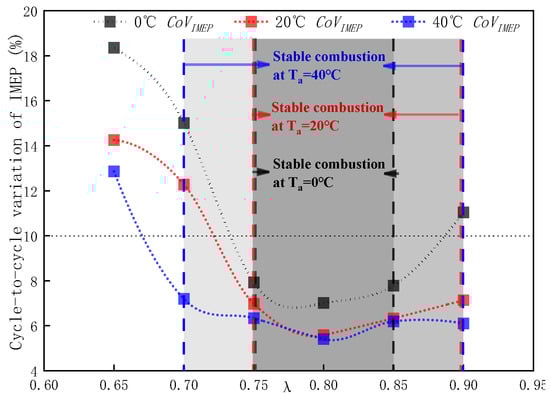
Figure 5.
Division of stable combustion interval.
When increases from 0 °C to 20 °C, the stable combustion range expands toward less rich mixtures, and the increase in can broaden the stable combustion range. For example, in Figure 5, 0.85~0.9. When increases from 0 °C to 20 °C and 40 °C, decreases significantly, and the combustion becomes more stable. The reason is that when 0 °C, is low and the fuel mass injected is less, resulting in the formation of a mixture concentration that is lower than the lean ignition limit. As increases, increases, which increases the amount of mixed gas participating in the combustion, thereby increasing the IMEP.
Compared with 20 °C, when 40 °C, the stable combustion range is extended toward richer mixtures. As shown in Figure 5, 0.70~0.75, and an increase in from 0 °C to 20 °C has no obvious effect on reducing the combustion cyclic variation. When is increased to 40 °C, the combustion cyclic variation is significantly reduced. This is because when 0 °C, is low, resulting in insufficient mixed gas involved in combustion. When rises to 20 °C, increases and the total amount of the mixture increases. However, due to the uneven distribution of the mixture, does not decrease significantly. When increases to 40 °C, the higher makes the mixture more uniform, the combustion is more stable, and is significantly reduced. However, when 0.70, the fuel concentration is too high and exceeds the ignition limit, resulting in the deterioration of the combustion state and an increase in instead.
Figure 6 depicts the relationship between and . The results show that, compared with the high , increasing has a greater effect on reducing in this intake temperature range. As shown in Figure 6, 0.90~0.75, and is smaller in the range of 0~40 °C compared to the range of 0~20 °C. At the same time, it was found that, compared with stable combustion, an increase in has a greater effect on reducing in unstable combustion. As shown in Figure 6, is much smaller in stable combustion than in unstable combustion.
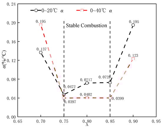
Figure 6.
Effect of intake temperature on the coefficient of variation of the indicated mean effective pressure.
Figure 7 presents the relationship between and output work. The results show that has a greater impact on the output work when is high. Moreover, compared with unsteady combustion, the combustion cycle variation has a more significant effect on the external output work of the engine in the steady combustion state. It can be seen from the figure that is much smaller in unstable combustion than in stable combustion. Compared to unstable combustion, in a stable combustion state, each 1% increase in combustion cycle variation leads to a more significant reduction in output work. This demonstrates the negative impact of the combustion cycle under stable combustion conditions. The effect of on the combustion cycle variation and engine work is greater.
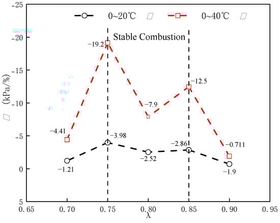
Figure 7.
Effect of combustion cycle variation on work output when 0~20 °C and 0~40 °C.
Figure 8 presents the impact of on output work. It can be seen from the figure that an increase in has a positive effect on the improvement of the engine output work, and the influence degree is different in different temperature ranges. When is increased from 0 °C to 20 °C, is approximately 0.13~0.21 kPa. When rises from 20 °C to 40 °C, increases significantly, reaching 0.23~0.86 kPa. This indicates that an increase in temperature has a more significant effect on the IMEP at higher .
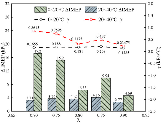
Figure 8.
Effect of increased intake air temperature on IMEP.
4. Conclusions
This study examined the effect of on combustion cycle variation in a two-stroke aviation kerosene piston engine under idle conditions. The influence of on the evaporation rate of aviation kerosene was analyzed, and a relationship was established between , combustion cycle variation, and work output. The key findings are as follows:
The influence of on the fuel evaporation rate is related to engine speed, and this correlation weakens as the speed increases. The increase in crankcase temperature promotes fuel evaporation.
The combustion work of the engine is negatively correlated with the combustion cycle variation; when is small, the combustion work is higher, and when is large, the combustion work is low.
When is low, increasing has a greater effect on reducing . When is within a higher range, the impact of combustion cycle variation on output power is more significant than the variation of itself.
An increase in expands the stable combustion range. In the range of 0~40 °C, the higher the inlet temperature, the larger the stable combustion range.
Author Contributions
Data curation, Y.L., Z.F. and X.W.; investigation, J.F.; methodology, J.W. and Z.H.; project administration, Z.H., Z.Z. and W.T.; resources, Z.H., Z.Z. and J.F.; software, Z.F. and X.W.; writing—original draft, J.W.; writing—review and editing, J.W., Z.H., Z.Z., W.T., J.F. and X.W. All authors have read and agreed to the published version of the manuscript.
Funding
This research was funded by the Sichuan Science and Technology Program [grant numbers 2024ZDZX0042 and 2023NSFSC0836], the Open Research Subject of Key Laboratory of Fluid Machinery and Engineering (Xihua University), Sichuan Province [grant number LTJX-2024005], and the Chunhui Plan of the Ministry of Education of the People’s Republic of China [grant numbers HZKY20220586 and HZKY20220569].
Data Availability Statement
The data presented in this study are available upon request from the corresponding author due to ethical and legal reasons.
Acknowledgments
We sincerely appreciate the valuable guidance and assistance of Lu Xu, Jiangeng Li, Buwei Deng, Xuantao Li, and Lin Wang from Xihua University.
Conflicts of Interest
The authors declare no conflicts of interest.
Nomenclature
| coefficient of variation of indicated mean effective pressure | |
| IAT ( | intake air temperature |
| IMEP | indicated mean effective pressure |
| average of indicated mean effective pressure | |
| difference in indicated mean effective pressure subtraction | |
| total fuel injection quality | |
| liquefied fuel quality | |
| crankcase temperature | |
| intake air temperature of 0 °C | |
| combustion cyclic variation increment per unit temperature | |
| output power increment per unit combustion cycle variation | |
| output power increment per unit temperature | |
| fuel evaporation rate | |
| excess air coefficient |
References
- Zhang, Q.; Du, F.R. Small Aero-Piston Engine Heavy Fuel Technology Development Summary. Small Intern. Combust. Engines Veh. Technol. 2014, 43, 81–85. [Google Scholar]
- Hu, J.; Liu, B.; Zhang, C.; Gao, H.; Zhao, Z.; Zhang, F.; Wang, Y. Experimental Study on the Spray Characteristics of an Air-Assisted Fuel Injection System Using Kerosene and Gasoline. Fuel 2019, 235, 782–794. [Google Scholar] [CrossRef]
- Suhy, P.J.; Evers, L.W.; Morgan, E.J.; Wank, J.E. The Feasibility of a Kerosene Fueled Spark Ignited Two-Stroke Engine. In Proceedings of the SAE Technical Paper Series. International Off-Highway & Powerplant Congress and Exposition, Milwaukee, WI, USA, 12 September 1991; p. 911846. [Google Scholar] [CrossRef]
- Chang, C.; Wei, M.; Ji, H. Experimental Research on Cold Start of PFI Two-Stroke Spark-Ignition Kerosene Engine. J. Energy Eng. 2020, 146, 04020030. [Google Scholar] [CrossRef]
- Rodney, H.; Greg, B.; Steven, A. High Specific Power Output Direct Injection 2-Stroke Engine Applications. In Proceedings of the Small Engine Technology Conference & Exposition, Bangkok, Thailand, 9 January 2005; p. 2005–32–0066. [Google Scholar]
- Huo, W.Y.; Lin, Y.Z.; Zhang, C.; Zhuang, C.Q. Research on N-Decane as Surrogate Fuel of Aviation Kerosene in Atomization Process. J. Aerosp. Power 2016, 31, 188–195. [Google Scholar] [CrossRef]
- Song, Z.L.M.S. Research on Mixture Formation and Combustion Characteristics of the Conical Spray in a Gasoline Direct Injection Engine; Jiangsu University: Zhenjiang, China, 2019. [Google Scholar]
- Li, X.H.; Jiang, D.M.; Shen, X.H. Study on Evaluated Methods of Pressure Cyclic Variation in Spark Ignition Engines. J. Intern. Combust. Engine 2000, 18, 171–174. [Google Scholar] [CrossRef]
- Zheng, Z.Q.; Yao, M.F.; Zhang, B.; Chen, Z. Cycle to Cycle Variation Experiment of Homogeneous Charge Compression Ignition Combustion. J. Tianjin Univ. 2005, 6, 485–489. [Google Scholar]
- Liu, S.; Zhang, L.; Wang, Z.; Hua, L.; Zhang, Q. Investigating the Combustion Stability of Shale Gas Engines under HHO. Fuel 2021, 291, 120098. [Google Scholar] [CrossRef]
- Maurya, R.K.; Agarwal, A.K. Experimental Investigation on the Effect of Intake Air Temperature and Air–Fuel Ratio on Cycle-to-Cycle Variations of HCCI Combustion and Performance Parameters. Appl. Energy 2011, 88, 1153–1163. [Google Scholar] [CrossRef]
- Wang, Q.G.; Wang, B.; Yao, C. Study on Cyclic Variability of Dual Fuel Combustion in a Methanol Fumigated Diesel Engine. Fuel 2016, 164, 99–109. [Google Scholar] [CrossRef]
- An, Y.; Raman, V.; Tang, Q.; Shi, H.; Sim, J.; Chang, J.; Magnotti, G.; Johansson, B. Combustion Stability Study of Partially Premixed Combustion with Low-Octane Fuel at Low Engine Load Conditions. Appl. Energy 2019, 235, 56–67. [Google Scholar] [CrossRef]
- Wang, Z.; Zhang, Z.F.; Xu, F.; Yang, D.B.; Wang, J.X. Study of Cycle Variation in a Multi-Cylinder Gasoline HCCI Engine. Chin. Intern. Combust. Eng. 2010, 31, 1–6. [Google Scholar] [CrossRef]
- Liu, J.F.; Cai, X.L.; Yang, Y.X.; Zhang, P.; Gao, J.; Fang, X. Study on Idle and Low-load Characteristics of FAI Two-stroke DISI Engine. Small Intern. Combust. Engines Motorcycles 2006, 05, 16–19. [Google Scholar]
- Su, T.; Ji, C.; Wang, S.; Cong, X.; Shi, L. Enhancing Idle Performance of an N-Butanol Rotary Engine by Hydrogen Enrichment. Int. J. Hydrogen Energy 2018, 43, 6434–6442. [Google Scholar] [CrossRef]
- Ozdor, N.; Dulger, M.; Sher, E. An Experimental Study of the Cyclic Variability in Spark Ignition Engines. In Proceedings of the International Congress & Exposition, Detroit, MI, USA, 1 February 1996; p. 960611. [Google Scholar] [CrossRef]
- Chen, L.L. Research on Numerical Simulation of Performance and Fuel Injection Control for Two-Stroke Kerosene Engine; Nanjing University of Aeronautics and Astronautics: Nanjing, China, 2009. [Google Scholar]
- Yu, W. Study on Engine Power Recovery with Diesel Methanol Dual Fuel at High Altitude; Jiangsu University: Zhenjiang, China, 2022. [Google Scholar]
- Li, A. Performance Study of Ammonia-DME Dual Fuel Engine; Harbin Engineering University: Harbin, China, 2023. [Google Scholar]
- Fjare, P.D. Feedback Speed Control of a Small Two-Stroke Internal Combustion Engine that Propels an Unmanned Aerial Vehicle. Master’s Thesis, University of Nevada, Las Vegas, NV, USA, 2014. [Google Scholar]
- Ji, C.; Wang, S. Strategies for Improving the Idle Performance of a Spark-Ignited Gasoline Engine. Int. J. Hydrogen Energy 2012, 37, 3938–3944. [Google Scholar] [CrossRef]
- Ozdor, N.; Dulger, M.; Sher, E. Cyclic Variability in Spark Ignition Engines A Literature Survey. SAE Trans. 1994, 103, 940987. [Google Scholar]
- Li, B.L.; Wei, M.X. Study on Combustion Cyclic Variation of Small Two-Stroke Aero-Engine. J. Aerosp. Power 2011, 26, 315–322. [Google Scholar] [CrossRef]
- Fu, K.M.; Wei, Y.; Xu, R.F.; Liu, X.Y. Combustion Cycle-to-Cycle Variations of Opposed-Piston Two-Stroke Gasoline Direct Injection Engine. Int. J. Engine Res. 2024, 25, 717–726. [Google Scholar] [CrossRef]
Disclaimer/Publisher’s Note: The statements, opinions and data contained in all publications are solely those of the individual author(s) and contributor(s) and not of MDPI and/or the editor(s). MDPI and/or the editor(s) disclaim responsibility for any injury to people or property resulting from any ideas, methods, instructions or products referred to in the content. |
© 2025 by the authors. Licensee MDPI, Basel, Switzerland. This article is an open access article distributed under the terms and conditions of the Creative Commons Attribution (CC BY) license (https://creativecommons.org/licenses/by/4.0/).