Article

Optimization of Load Rejection Regulation for Compressed Air Energy Storage

1
School of Electrical Engineering, Guizhou University, Guiyang 550025, China
2
Postgraduate Workstation of Guizhou Power Grid Co., Ltd., Guiyang 550002, China
3
Electric Power Research Institute of Guizhou Power Grid Co., Ltd., Guiyang 550002, China
4
Guizhou Chuangxing Electric Power Research Institute Co., Ltd., Guiyang 550002, China
*
Author to whom correspondence should be addressed.
Energies 2025, 18(2), 254; https://doi.org/10.3390/en18020254
Submission received: 23 November 2024 / Revised: 19 December 2024 / Accepted: 7 January 2025 / Published: 8 January 2025
(This article belongs to the Section D: Energy Storage and Application)

Abstract

:
Given the shortcomings of compressed air energy storage systems in emergency response in power auxiliary research, especially in the scenario of decoupling from the power grid, an in-depth analysis is conducted. A set of energy release stage models with 10 MW compressed air energy storage equipped with an anti-overspeed system are set up. This research mainly focuses on the speed control of the two stages of the decoupled compressed air energy storage system: the soaring speed and the system recovery standby. By analyzing the influence of different cut-off valve actions on the decoupled speed, it is concluded that the key factor of speed control is the isolated expander. After the speed is controlled, the main factors affecting the speed control in the system are analyzed. As long as the expander is cut off, the high-temperature and high-pressure air will remain in the internal pipe and the heat exchanger of the system, which will cause the speed of the generator to soar again. A new load rejection control strategy is proposed based on the above analysis, in which the speed is smoothly reduced to 3000 r/min by the cut-off valve at the front end of the expander, and the residual working fluid is discharged. The results show that the optimized load rejection strategy reduces the speed increment by 89% compared to the traditional strategy, and reduces the recovery standby practice by 65%. Under 75% load conditions, the optimized load rejection strategy reduces the speed increment by 87% and the recovery standby practice by 41% compared to the traditional strategy. At 50% load conditions, the optimized load rejection strategy reduces the speed increment and standby time by 86% and 33%, respectively, compared to the traditional strategy. The key speed control index of the optimized load rejection strategy is much better than the traditional strategy, which significantly improves the control effect of accident emergencies.

1. Introduction

With the rapid development of new energy, the scale of power generation represented by the energy landscape is constantly expanding. The biggest problem of wind power generation is its unstable energy output [1]. In addition, the lack of inertia support also presents some challenges to the grid connection of clean power. Grid connection is an important topic in developing new energy and one of the key research directions in assisting grid connection through large-capacity energy storage systems [2,3]. Compressed air energy storage (CEAS) is a large-capacity, clean, and low-carbon type of energy storage. With the increasing demand for new types of energy storage in the electricity market, due attention has been given to it [4].
In 1949, CAES technology was first proposed by German engineer Stal Laval [5]. Scholars, both domestically and abroad, have conducted related research and practical application studies and have planned and implemented many CAES application projects. The main application of energy storage technology is to support the balance of power and load of the power system; the operation state of the system is complex and dynamic [6]. How to achieve cooperative operation with power systems is an important topic in the development and application of energy storage technology. Li et al. [7] analyzed the dynamic characteristics of the system energy storage and release stages, and established the control model of grid-connected speed regulation system. It provides a basic control strategy for the coupling of an adiabatic CAES system and power system. Wen et al. [8] proposed a method for CAES systems to respond to the primary frequency modulation of the power grid in both directions, and set parameters according to the characteristics of the CAES system, to enhance the ability to absorb new energy. Kamyar et al. [9] developed a new design method for a CAES system based on the performance requirements of the Ontario power grid by analyzing the actual operation data for a whole year. Based on the characteristics of the CAES system. Based on linear auto disturbance rejection control (LADRC), Meng et al. [10] proposed a linear ADRC strategy in which the bandwidth parameters can be adjusted adaptively, which achieves a smooth CAES grid connection. Wang et al. [11] proposed a control strategy for a compressed air energy storage system in grid-connected and off-grid modes. In grid-connected mode, only the active and reactive power output to be controlled because of the voltage and frequency support provided by the grid. In the off-grid mode, the voltage and frequency fluctuations are effectively stabilized by considering the voltage and frequency control strategy to ensure the continuous and stable operation of the system. It provides a control strategy for the connection and disconnection between the CAES system and the power grid or load side. Ban et al. [12] established an optimization model considering the smoothness of the load curve and the voltage improvement ability. Based on the characteristics of the AA-CAES energy storage system, with the aim of minimizing voltage offset and load curve variance, a flexible access method for the energy storage system based on intelligent soft switching is proposed, to ensure the coupling between the CAES and the power system is smoother. Zhang et al. [13] built a wide-working condition simulation model depicting the operation feasible region under constant pressure and sliding pressure mode, and put forward the operation mode to deal with variable operating conditions. Comparing the three models, analyzing the relevant effects and laws, and providing the theoretical support for improving the flexibility of different scenarios, are the aims of this study.
Presently, power auxiliary research is mainly focused on active and reactive power regulation, but the research on emergency response is relatively less. Load rejection, as an emergency control under extreme conditions, is very important for the safe and reliable operation of CAES systems [14]. Xu et al. [15] analyzed the influence of internal parameters of liquid compressed air energy storage expansion power generation systems on load rejection, but did not reduce the method and strategy for a rise in speed. Wen et al. [16] divided the overspeed process into three stages by studying the load rejection process of a 10 MW CAES system. At the same time, the calculation method for the maximum speed is given, which provides support for the control of the load rejection regulation of the CAES system. Yang et al. [17] studied the problem of power grid decoupling in the process of load rejection and proposed a control scheme for the surge of generator speed, which is controlled by interstage valves, but there is no research on the strategies for restoring idling of the unit.
When a CAES outputs electric energy, if the load on the side of the grid changes sharply or even decouples, or if there is a fault within the system, it needs to be disconnected from the power system immediately, and the imbalance between the output power and load will lead to a surge in rotor speed [17]. In addition, when the rotor is controlled, the control means to restore the standby state of the unit (the rotor maintains 3000 r/min idling) should be considered. As shown in Figure 1, this paper will establish a 10 MW adiabatic CAES model, analyze the main factors affecting the CAES load rejection control from the two-speed control stages of decoupling and system recovery, and establish the optimal anti-overspeed strategy by considering the rapid deceleration and recovery of the system, to deal with the emergencies at the power grid end and load end, and ensure the safe operation of the CAES system.

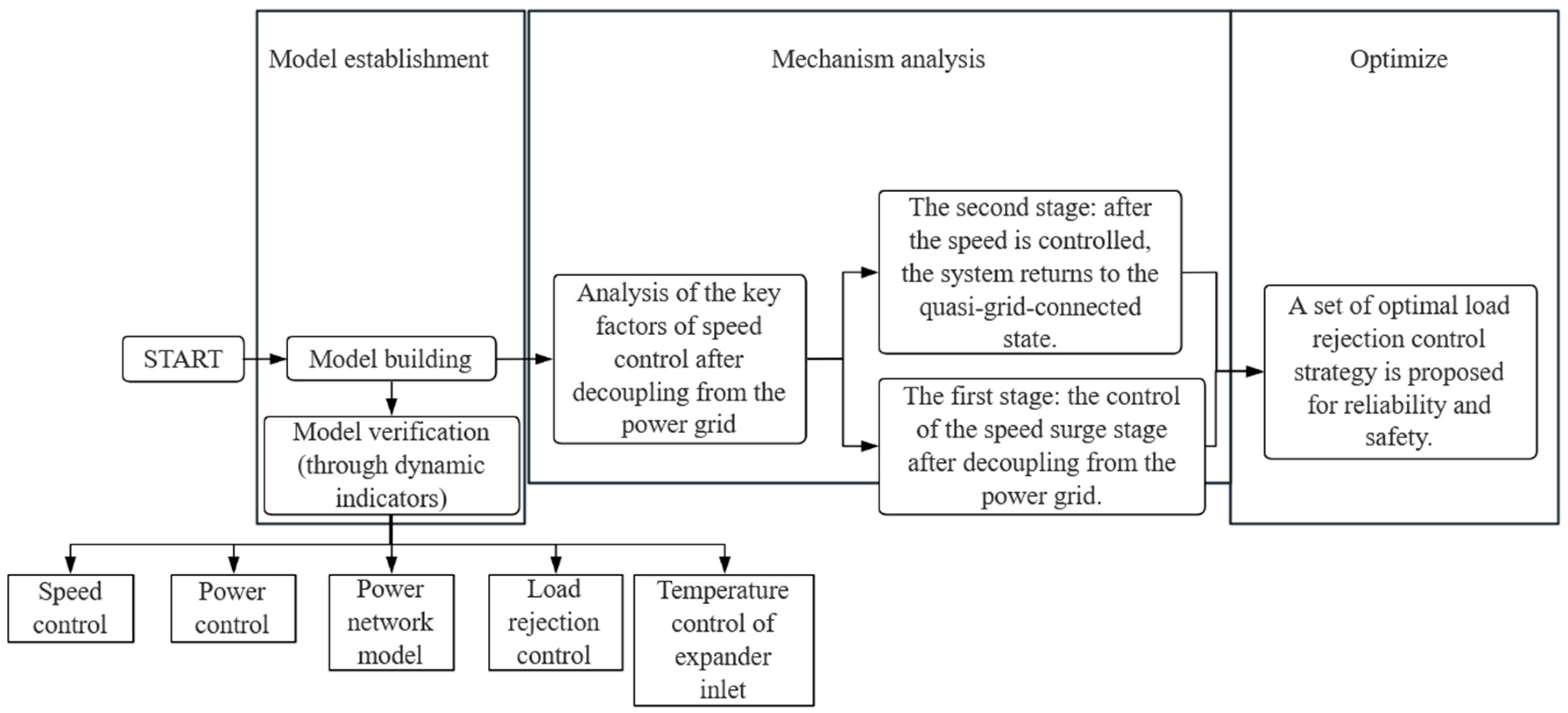
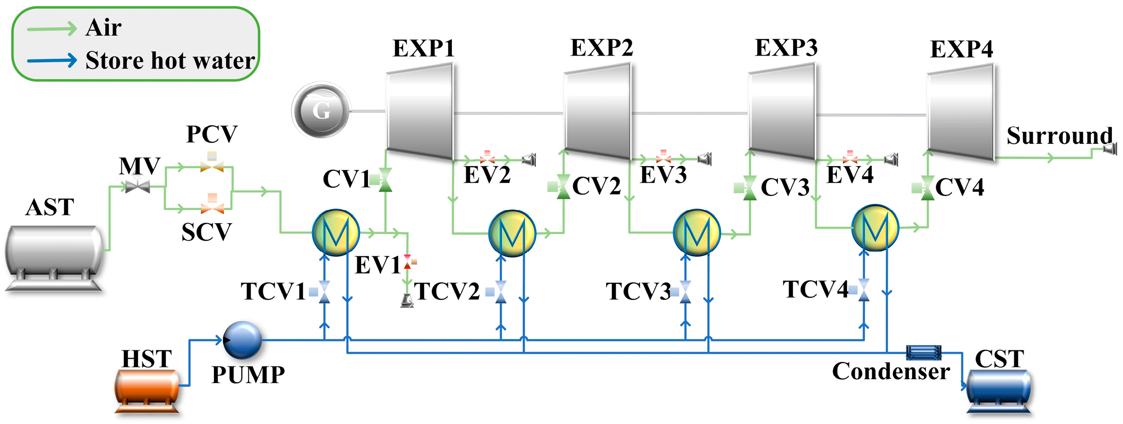
2. Model Establishment

This study examines the load rejection and anti-overspeed action carried out by the unit in response to regulation when the CAES system is suddenly separated from the power grid and the unit load suddenly drops to zero. Based on the purpose of this research, the energy release process model of the 10 MW CAES system is established. To reduce the complexity of the model, the following assumptions are made in the modeling process: the flow and working process of the working fluid in the system is adiabatic, and the valve action is completed within 0.1 s.

2.1. Mathematic Model

This paper is based on the modular simulation software Apros (https://www.apros.fi/), whose internal modules are the foundation of the simulation system. The following is the mathematical model of the main application modules of the model:

2.1.1. Gas Storage Tank

Quality change in gas storage tank:
d ρ d t = m i n m o u t V
where ρ is the air density in the gas storage chamber; m i n is the inflow flow rate; m o u t is the outflow rate; and V is the volume of the gas tank.
Under the condition of constant volume, the energy conservation equation in the gas tank is calculated as follows:
d ( m u ) d t = m i n h i n m o u t h o u t h a c A c ( T T a c )
where m is the gas mass; h i n and h o u t are the enthalpy of the inflow and outflow gas; h a c is the heat transfer efficiency between the gas and the gas storage wall; A c is the wall area of the gas storage chamber; T and T a c are the air temperature and wall temperature in the gas storage chamber, respectively.
The gas temperature and pressure in the gas tank vary with time as follows [18]:
d T a c d t = T a c M u k 1 d M u d t 1 M u c v h a A ( T a c T a ) d p d t = R g V C V [ d m d t c p T a c h a A T a c T a ]
where p is the gas pressure in the tank; R g is the gas constant of the air; c p is the specific heat capacity of the air under constant pressure; T a c is the gas temperature in the tank; t is the time of power generation; M u is the gas mass in the tank; k is the air compression index; c v is the constant volume specific heat capacity of the air, h a is the convective heat transfer coefficient in the gas storage tank; A is the inner surface area of the gas storage tank and T a is the wall temperature of the gas storage tank.

2.1.2. Expander

The work completed by the expander can be calculated by the following formula [7]:
θ = m ( h q h 2 )
where θ is the power of the expander and m is the air mass flow through the expander.
The mechanical power generated by the expander can be calculated by the mass flow rate and enthalpy drop of the expander:
P m e k = ( m h )
where P m e k is the mechanical work of the expander.

2.1.3. Shaft

The rotor’s moment of inertia has a great influence on the dynamic response and adjustment of the system [17]:
J d w d t = ( t t t c t l )
where J is the moment of inertia; w is the shaft speed; t t , t c , and t l are the output torque of the expander, the input torque of the compressor, and the load absorption torque, respectively.

2.1.4. Heat Exchanger

In the AA-CAES power generation system, the heat exchanger and the expander are arranged in series. After the air flows into the heat exchanger, the heat exchange between the air and the tube wall is as follows [7]:
Q h = A h ( T h T w ) δ 2 K w + 1 a h
The heat exchange between the heat transfer medium and the tube wall is as follows:
Q c = A c ( T c T w ) δ 2 K w + 1 a c
where δ is the thickness of the pipe wall; T w is the average temperature of the tube wall; T h is the air temperature in the tube wall; T c is the average temperature of the heat transfer medium; K w is the thermal conductivity of the tube wall; a c and a h are the convective heat transfer coefficients of the inner and outer walls; A c and A h are the area of the inner and outer walls, respectively.
The boundary conditions of the model and the rated operating parameters of the expander refer to the actual engineering case; the parameters of the Bijie 10 MW AA-CAES system in Guizhou, China [19]. The boundary conditions are shown in Table 1.
Table 2 shows the design parameters for the rated operation of all levels of expander.
Table 3 shows the design parameters of rated working conditions of heat exchangers.

2.2. Modeling Idea and Verification

This paper is based on the energy release phase model of a 10 MW CAES system. The installation of the cut-off valve in front of the air inlet of each stage expander and the exhaust valve in the front area of the cut-off valve is shown in Figure 2. In addition, the system is equipped with a corresponding temperature, speed, power, and load rejection regulation system, in which the PID governor is used as the control module [20].

2.2.1. Speed Control Model

The speed control system adopts the control strategy of “slow landing”; before the actual speed reaches 2900 r/min, the real-time target speed is set to 100 r/min per minute, and after the speed reaches 2900 r/min, the real-time target speed is obtained by the following formula [7]:
v = K 2 × ( 3000 n )
where K 2 is the acceleration coefficient and n is the actual speed.
Figure 3 shows the process of speed climbing.

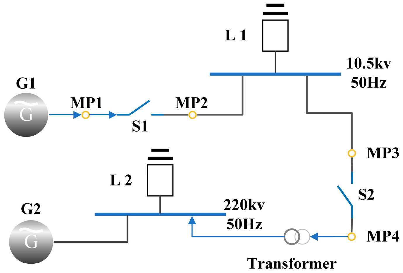
2.2.2. Power Network Model

As shown in Figure 4, the system outputs power through the generator G1. One part is used for auxiliary power, and the other is put into the 220 kV power grid. The large power grid module is supported by generator G2 and connected to load L2. In order to facilitate the measurement of parameters, a measurement point MP is inserted between each module.

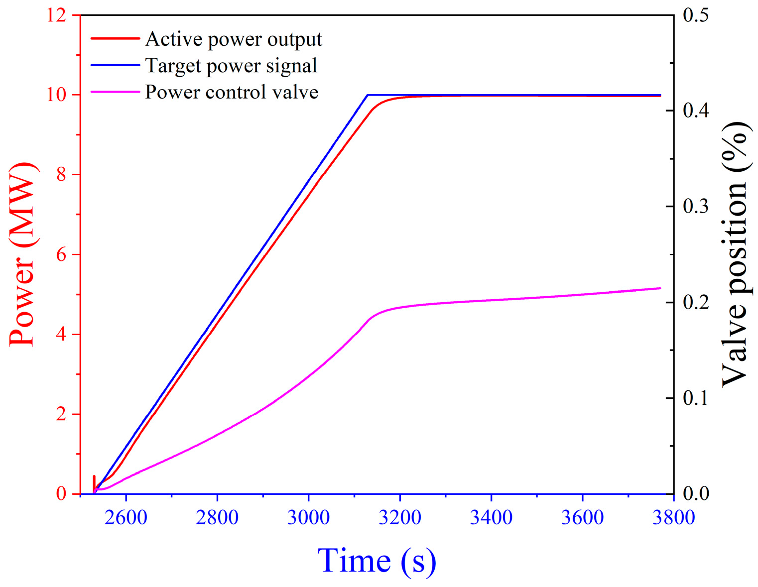
2.2.3. Power Control Model

As shown in Figure 5, with the progression of the energy release process, the air pressure and temperature inside the tank gradually decreases, which has a certain impact on the valve opening in the control process.
As shown in Figure 6, after being connected to the grid, the target output power is set to 10 MW. Through regulation and control, the output active power of the system increases gradually and finally reaches the target power. In addition, the inlet pressure and output power of all levels of expanders gradually increases, and finally reaches the design value, as shown in Figure 7 and Figure 8.
The load dynamic adjustment test simulates the change of load from 10 MW to 7 MW, as shown in Figure 9.

2.2.4. Temperature Control Model of Expander Inlet

In the CAES system, temperature is an important factor affecting the output work of the system, and the temperature control is mainly aimed at the inlet temperature of the steam expander. The parameters are designed according to the rated working conditions, and the target temperature is set to 85 °C. The temperature is adjusted by controlling the heating control valve at the front end of the heat exchanger, and the inlet temperature of the steam expander can be stabilized during the operation of the unit.
Figure 10 shows the change of inlet temperature of all levels of expander after climbing from rotational speed to grid connection.
When the system is connected to the grid, the temperature control is turned on, the temperature gradually rises to the set temperature, and the maximum overshoot is 1 °C. In power generation, the temperature is stable at 85 °C. Considering the relationship between the annual average ambient temperature under the local climatic conditions and the ambient temperature of the model boundary conditions, the inlet temperature of all expanders is set at 85 °C, which is slightly higher than the actual set temperature.

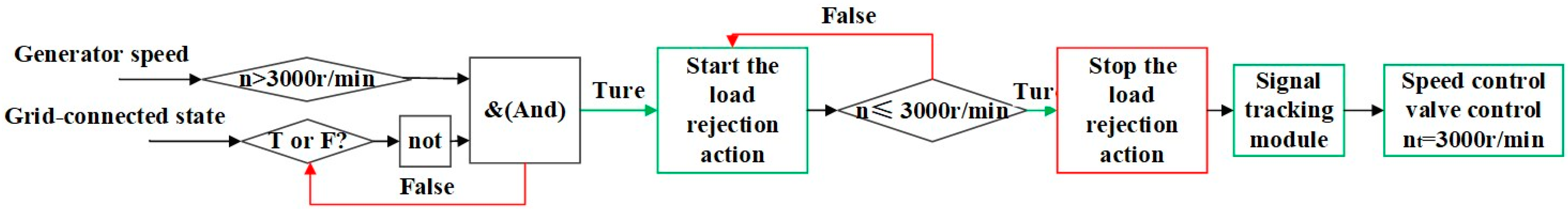
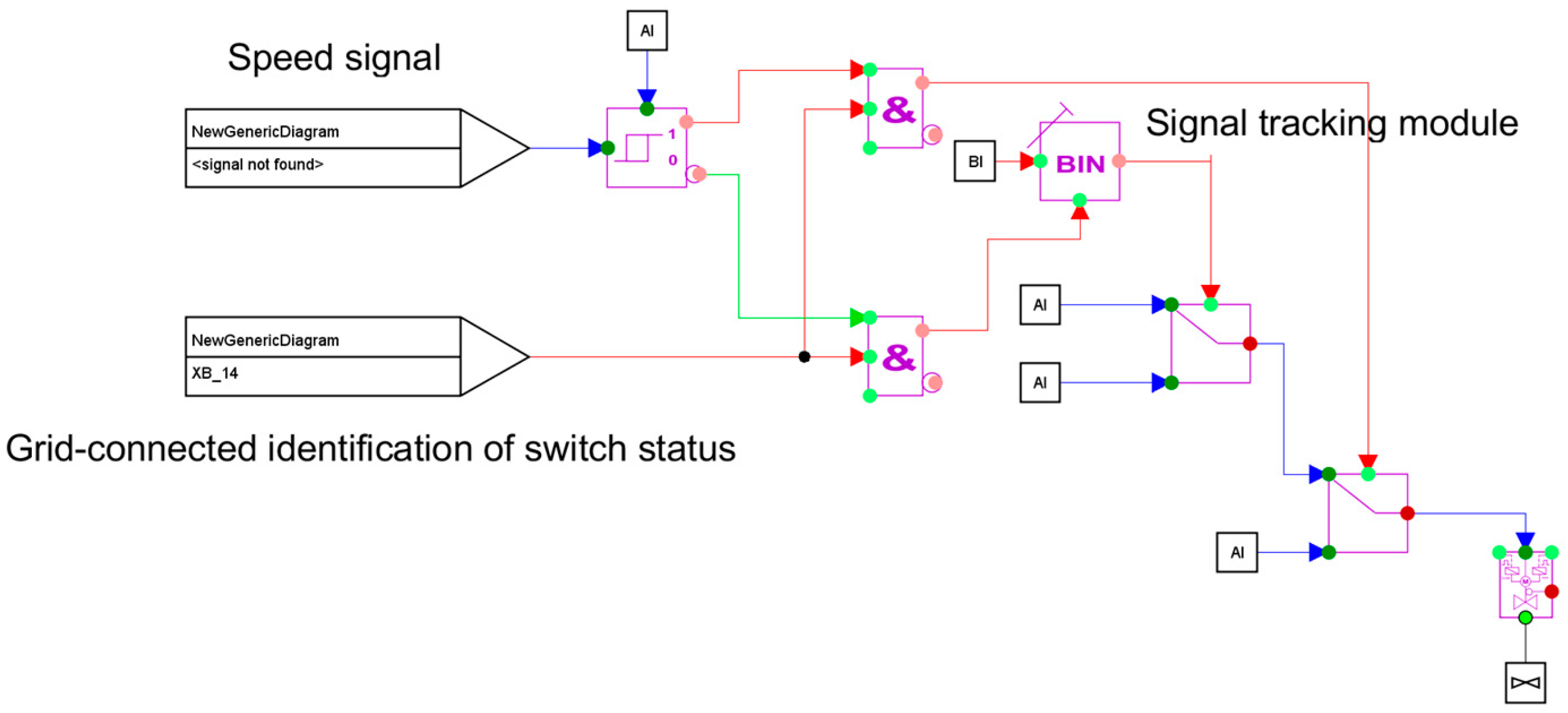
2.2.5. Load Rejection Control Model

The control object of the load rejection test control system includes the cut-off and exhaust valves at the front end of the expander, which are operated manually according to the test requirements. Once the control module of the corresponding valve starts, and when it identifies the situation of leaving the power grid and detects the increase of rotational speed, it will automatically carry out load rejection. In addition, the speed control, power control, and temperature control models are all equipped with anti-overspeed response control. When it is identified that the system is decoupled from the power grid and the speed exceeds 3000 r/min, the opening of the control valve is directly reduced to zero.

3. Mechanism Analysis

3.1. Decoupling Guard Against the Overspeed Stage

After the CAES system is decoupled from the power grid, the load suddenly drops to zero, and the speed will soar due to the imbalance between load and output power. As shown in Table 4, the following experiments will explore the effect of cut-off valve action in different positions on speed control.
As shown in Figure 11, when speed control is conducted by closing the first-stage cut-off valve at 100% rated load, the maximum speed and speed recovery time do not differ from that of closing the last-stage cut-off valve. The effect of speed control by closing the second-stage and third-stage cut-off valves is superior. Similarly, under the other two load conditions, the control effect of the cut-off valve’s action in different positions on speed also varies, indicating that the cut-off position is not the key factor affecting speed control.
As shown in Table 5, isolating the intake air of the expander and testing its influence on the speed control effect.
As shown in Figure 12, by turning off the truncation stepwise, the effect of speed control is improved stepwise. Preventing the refrigerant from entering all levels of the expander is the key to speed control.

3.2. System Recovery Standby Phase

Below, the pipes and heat exchangers at the front end of the expander inlet are divided into four areas. After testing different cut-off valves, the residual working fluid parameters in the four regions are tested.
As shown in Figure 13, after operating different cut-off valves, the residual working fluid in the pipes and heat exchangers at the front of each cut-off valve cannot be released due to the partitioning of the pipeline, and the pressure and temperature of these gases are higher. In addition, after the operation of the cut-off valve, the air in the low pressure area will be compressed to produce heat, and the heat will not flow out in time, resulting in an increase in the temperature in this area. As can be seen from Figure 13a–c, the rise in temperature is more significant when there is more residual working fluid.
As shown in Figure 14, under three different operating conditions, the speed is controlled by closing all the cut-off valves, and when the speed is reduced to 3000 r/min, the speed increases again when the system resumes. Therefore, it is necessary to exhaust the residual working fluid.

3.3. Strategy Analysis

As shown in Figure 15 and Figure 16, when the CAES system outputs electric energy, if the equipment at the power grid or load end is suddenly decoupled from the system, and the instantaneous output power and load are seriously out of balance, the rotor speed will immediately soar. At this time, the load rejection regulation system will recognize the changes in the two signals of the grid connection and system overspeed, so it will execute load rejection. As shown in Figure 17, the speed surge is suppressed by closing the interstage cut-off valve, while the interstage exhaust valve is opened to discharge high temperature and high pressure air in the pipe and heat exchanger. When the rotor speed of the system is reduced to 3000 r/min, the load rejection regulation system is closed, the cut-off valve is fully open, and the exhaust valve is fully closed. The load rejection control system is locked in the closed state through the signal tracking module, and finally, the rotor speed of 3000 r/min is adjusted by the speed control valve to enter the standby grid-connected state.
The traditional load rejection action is to control the speed by closing the cut-off valve at the front end of the first-stage expander. When the speed is controlled, the speed control valve (SCV) maintains idling. According to the state of the power network model, the relevant parameters of the system are set in the same way, and only the load rejection regulation strategy is different. Now, the regulation effects of the optimized load rejection strategy and the traditional load rejection strategy are compared.
As shown in Figure 18, the speed increment of the traditional strategy is 312 r/min, the system recovery standby time is 303 s, and the speed increment of the new strategy is only 33 r/min. The recovery standby time of the system is 106 s, the speed increment is reduced by 89%, and the recovery standby practice is reduced by 65%. At 75% load, the speed increment of the traditional strategy is 222 r/min, the system recovery standby time is 175 s, the speed increment of the new strategy is only 30 r/min, the system recovery standby time is 104 s, the speed increment is reduced by 87%, and the recovery standby practice is reduced by 41%. At 50% load, the speed increment of the traditional strategy is 133 r/min, the system recovery standby time is 150 s, the speed increment of the new strategy is only 19 r/min, the system recovery standby time is 101 s, the speed increment is reduced by 86%, and the recovery standby time is reduced by 33%. The speed control effect is greatly improved (the speed increment is the difference between the maximum rotation speed and the standby speed of 3000 r/min caused by the speed surge resulting from the decoupling of the CAES system and the load, and the decrease of the speed is helpful due to the safety and stability of the system). The recovery standby time of the system refers to the time it takes from the moment the system is decoupled from the load to when the rotor of the CAES unit is maintained until 3000 r/min can be connected to the grid. Both indicators reflect the effect of the regulation strategy. The speed control effect of the optimized load rejection strategy is better than the traditional strategy by a great extent.

4. Conclusions

In this paper, the modeled CAES system equipped with a speed control device is built, and the main factors affecting CAES load rejection regulation control are analyzed from two speed control stages: the decoupling moment and system recovery. The optimal anti-overspeed strategy is established to address speed surges caused by emergencies and ensure the safe operation of the CAES system. The main conclusions are as follows:
(1)
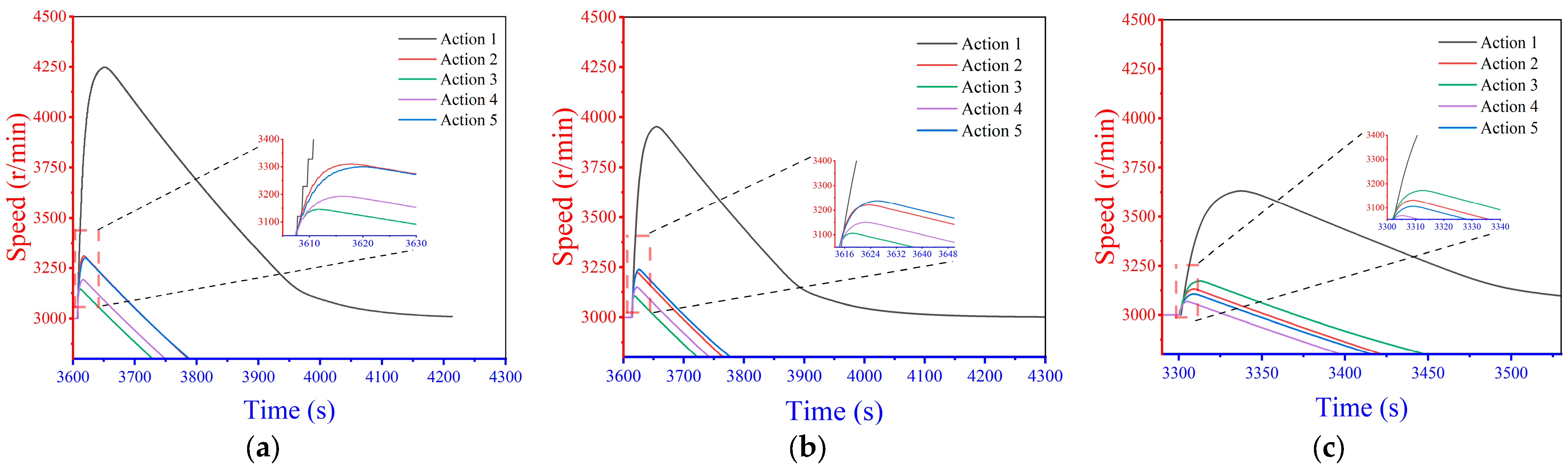
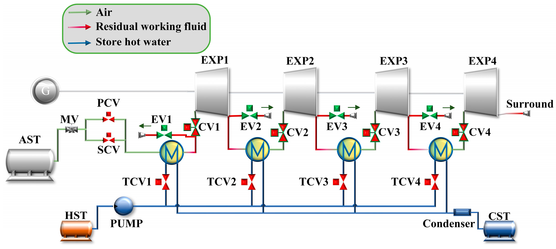
The influence of load rejection action from all levels of the cut-off valve on rotor speed after decoupling between the system and load under different working conditions is analyzed, and it is concluded that the residual working fluid is the key to speed control. For a multi-stage expansion CAES system, the only speed control valve (SCV) is limited, so the speed surge can be well prevented by closing the load rejection action of the front-end cut-off valves for all expander levels;
(2)
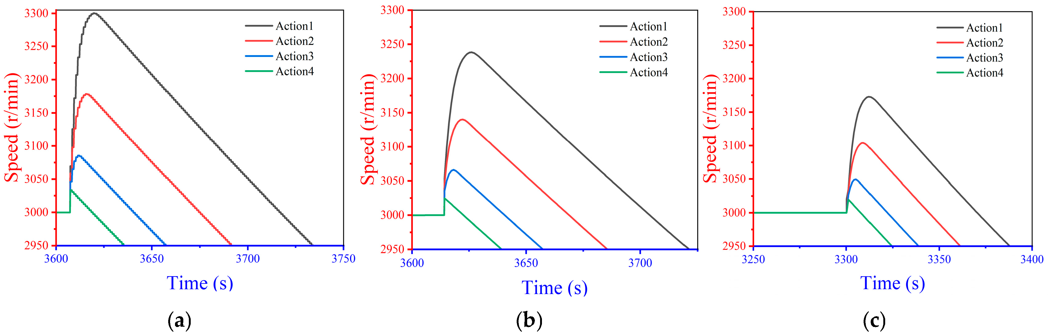
After the operation of the cut-off valve, the speed is quickly controlled, but through analysis of the main factors affecting speed control in the system, after the expander is cut off, high-temperature and high-pressure air will be left in the pipes and heat exchangers in the system, which will cause the speed of the generator to soar again, so it is necessary to discharge the residual working fluid;
(3)
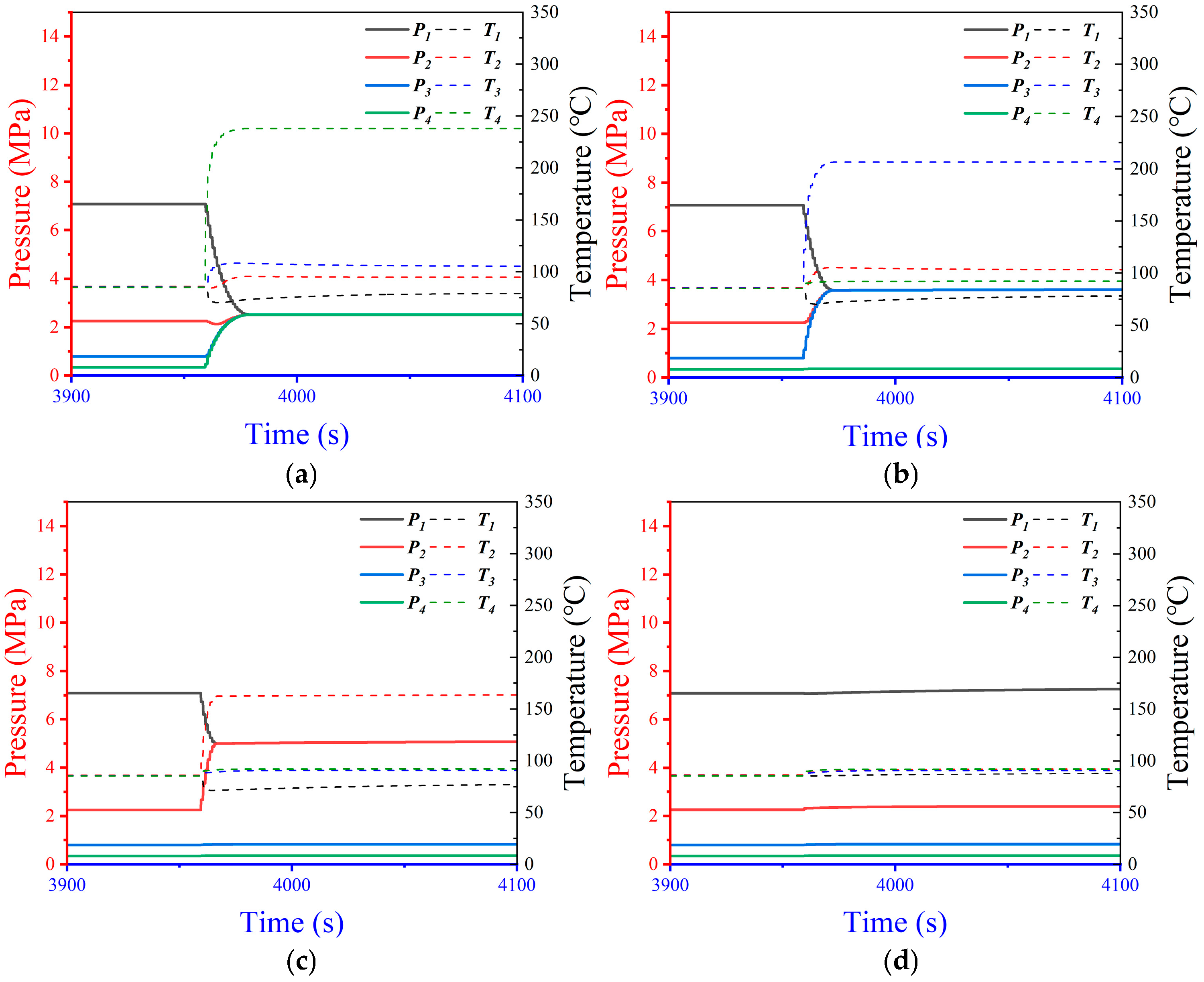
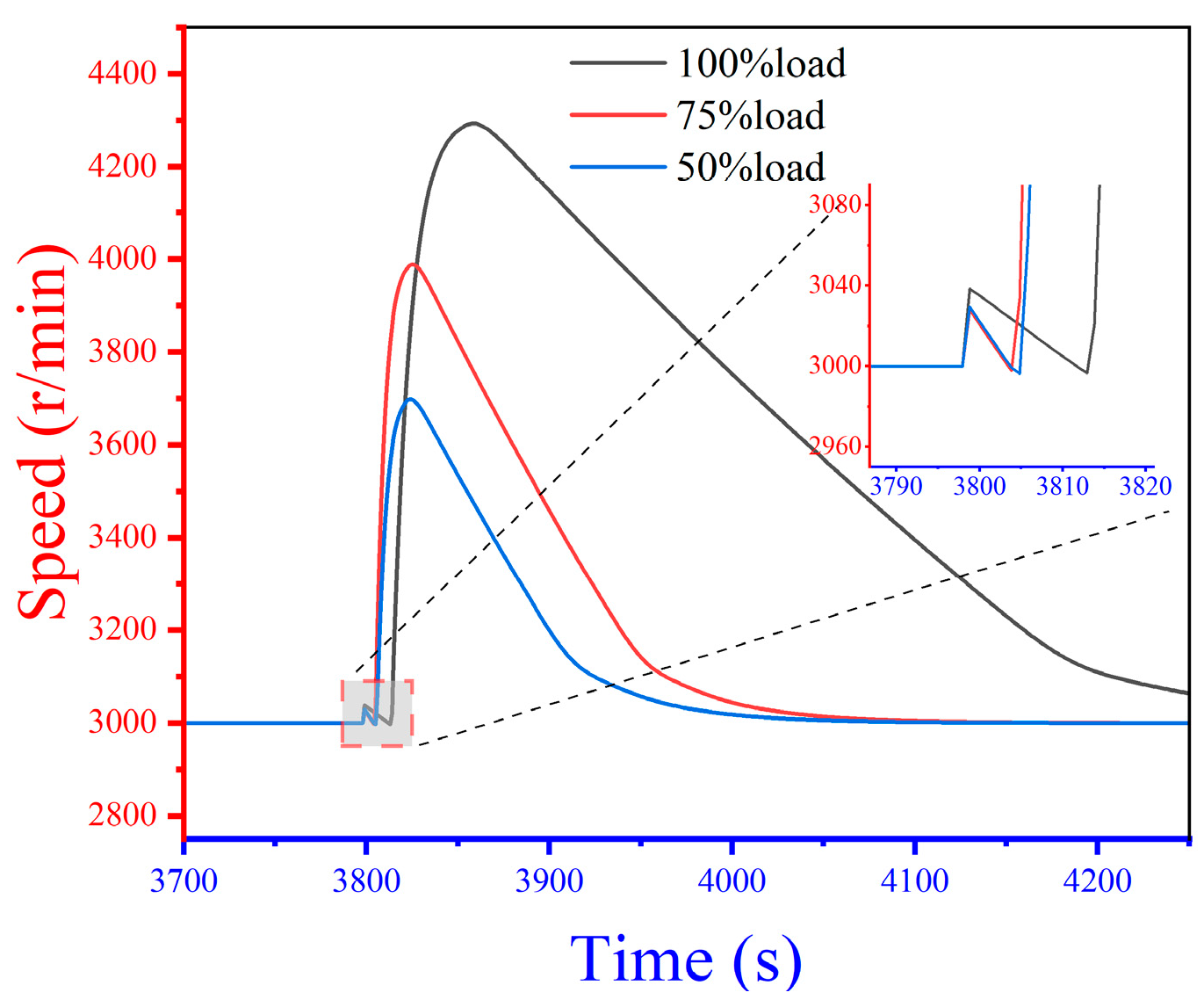
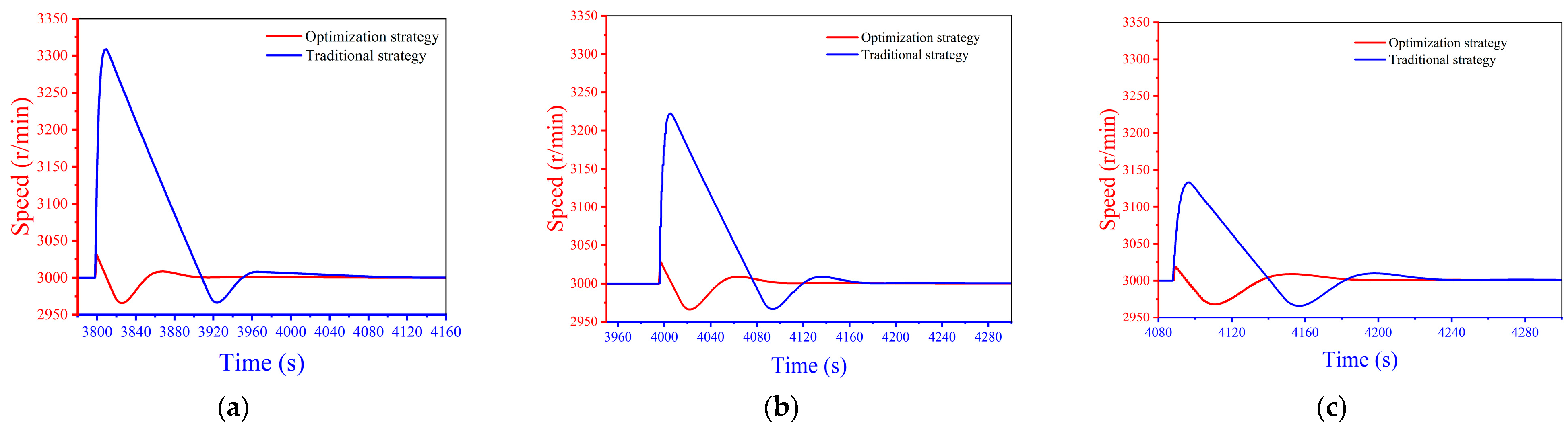
Aiming at the key factors of load rejection control of CAES, a new control strategy is proposed; through the action of the cut-off valve between the stages of expanders, the rotational speed is steadily reduced to less than 3000 r/min, and the residual working fluid is discharged. The results show that under a 100% load condition, the speed increment of the optimized load rejection strategy is reduced by 89% compared to the traditional strategy, and the recovery standby practice is reduced by 65%. Compared with the traditional strategy, the speed increment of the optimized load rejection strategy is reduced by 87% and the recovery standby practice is reduced by 41%. Under 50% load conditions, the speed increment of the optimized load rejection strategy is reduced by 86%, and the recovery standby time is reduced by 33%. The speed control effect of the optimized load rejection strategy is much better than that of the traditional strategy.

Author Contributions

Methodology, Y.W. and X.W.; software, S.Z.; validation, Y.W. and S.Z.; formal analysis, Y.W. and S.Z.; investigation, X.W.; resources, X.W. and S.Z.; data curation, X.W. and S.Z.; writing—original draft, Y.W.; writing—review & editing, X.W.; visualization, Y.W.; supervision, X.W., S.Z., Q.F., H.Y. and C.W.; project administration, X.W. and S.Z.; funding acquisition, X.W. All authors have read and agreed to the published version of the manuscript.

Funding

This work was financially supported by the Key Technologies for Performance Optimization of Compressed Air Energy Storage Auxiliary Service, grant number GZKJXM20222304; and the Project of Scientific and Technological Innovation Talents Team in Guizhou Province, grant number CXTD ([2022] 008).

Data Availability Statement

The original contributions presented in the study are included in the article, further inquiries can be directed to the corresponding authors.

Conflicts of Interest

Authors Yinghao Wu and Chao Wu were employed by the company Postgraduate Workstation of Guizhou Power Grid Co., Ltd. Authors Xiankui Wen, Qiang Fan and Huayang Ye were employed by the company Electric Power Research Institute of Guizhou Power Grid Co., Ltd. Author Shihai Zhangwas employed by the company Guizhou Chuangxing Electric Power Research Institute Co., Ltd. The remaining authors declare that the research was conducted in the absence of any commercial or financial relationships that could be construed as a potential conflict of interest.

References

  1. Razmi, A.R.; Soltani, M.; Ardehali, A.; Gharali, K.; Dusseault, M.; Nathwani, J. Design, thermodynamic, and wind assessments of a compressed air energy storage (CAES) integrated with two adjacent wind farms: A case study at Abhar and Kahak sites, Iran. Energy 2021, 221, 119902. [Google Scholar] [CrossRef]
  2. Liu, X.C.; Mei, S.W.; Ding, R.C.; Zhong, S.Y.; Zhang, J.F.; Xie, N.N.; Chang, Y.; Zhang, T. Present situation, Development trend and Application Prospect of compressed Air Energy Storage Engineering. Electr. Power Autom. Equip. 2023, 43, 38–47+102. [Google Scholar] [CrossRef]
  3. Lai, D.H.; Luo, W.F.; Huang, J.H. Power adaptive control of hybrid energy storage multi-microgrid based on edge calculation. Big Data Electr. Power 2023, 26, 28–35. [Google Scholar] [CrossRef]
  4. Aquilina, L.; Sant, T.; Farrugia, R.N.; Licari, J.; Spiteri Staines, C.; Buhagiar, D. Measurements and Modelling of the Discharge Cycle of a Grid-Connected Hydro-Pneumatic Energy Storage System. Energies 2024, 17, 1597. [Google Scholar] [CrossRef]
  5. Yang, D.H.; Wen, X.K.; Zhong, J.L.; Feng, T.; Deng, T.T.; Li, X. Compressed Air Energy Storage System with Burner and Ejector. Energies 2023, 16, 537. [Google Scholar] [CrossRef]
  6. Cheng, Z.W. Off-Condition Performance Analysis and Design Optimization of Low Temperature Adiabatic Compressed Air Energy Storage System. Ph.D. Thesis, Zhejiang University, Hangzhou, China, 2019. [Google Scholar]
  7. Li, P.; Yang, C.; Sun, L.; Xiang, J.; Wen, X.; Zhong, J.; Deng, T. Dynamic characteristics and operation strategy of the discharge process in compressed air energy storage systems for applications in power systems. Int. J. Energy Res. 2020, 44, 6363–6382. [Google Scholar] [CrossRef]
  8. Wen, X.K.; Zhang, H.F.; Yang, D.H.; Zhong, J.L.; Feng, T.Y. Compressed air energy storage participates in the research of primary frequency regulation of power grid in both directions. Autom. Instrum. 2021, 42, 67–70+76. [Google Scholar] [CrossRef]
  9. Kamyar, R.; Ehsan, S.; Roydon, A.F. A comprehensive data-driven study of electrical power grid and its implications for the design, performance, and operational requirements of adiabatic compressed air energy storage systems. Appl. Energy 2020, 257, 113990. [Google Scholar]
  10. Meng, J.H.; Sun, Y.X.; Zhang, Z.L.; Wang, C.Y. Compressed Air Energy Storage Linear Auto-Disturbance Rejection Smooth Grid-Connected Control Strategy with Adaptive Bandwidth Parameters. J. Power Supply 2024, 1–17. Available online: http://kns.cnki.net/kcms/detail/12.1420.tm.20240725.0916.002.html (accessed on 1 November 2024).
  11. Sheng, W.; Xu, Z. Research on load rejection protection of PWR power plants at different power levels. In Proceedings of the 2019 IEEE Innovative Smart Grid Technologies—Asia (ISGT Asia), Chengdu, China, 21–24 May 2019; pp. 525–530. [Google Scholar] [CrossRef]
  12. Ban, G.B.; Ma, X.H.; Ouyang, Z.Y.; Yu, Y.X.; Yuan, X.F.; Liu, L. Research on peak-cutting and valley-filling strategy considering flexible access of energy storage system. Power Syst. Big Data 2021, 24, 1–8. [Google Scholar] [CrossRef]
  13. Zhang, X.; Chen, L.J.; Cui, S.; Liu, H.C.; Mei, S.W. Analysis of operational feasible region of advanced adiabatic compressed air energy storage system under wide operating conditions. Grid Technol. 2024, 1–10. [Google Scholar] [CrossRef]
  14. Wang, J.H.; Zhao, J.; Zhong, J.L.; Wang, S.B.; Xu, Z.F. Cause analysis and treatment of overspeed in load rejection test of supercritical unit. Therm. Power Gener. 2018, 47, 115–119. [Google Scholar] [CrossRef]
  15. Xu, G.Z.; Liang, L.X.; Lu, C.; Cui, S.S.; Bai, Z.W.; Song, J.; Deng, Z.F.; He, Q. Study on speed rise characteristics of expander rotor during load rejection of liquefied air energy storage system. Therm. Power Gener. 2020, 49, 72–79. [Google Scholar] [CrossRef]
  16. Wen, X.K.; Zhong, J.L.; Deng, T.T.; Li, Q.M. Method to Calculate Maximum Speed of Turbine Expander of 10MW CAES after Load Rejection. In Proceedings of the 2019 IEEE International Conference on Power, Intelligent Computing and Systems (ICPICS), Shenyang, China, 12–14 July 2019; pp. 576–578. [Google Scholar] [CrossRef]
  17. Yang, C.; Li, P.; Sun, L.; Chai, J. Strategy of load rejection and overspeed prevention of compressed air energy storage expansion generator. J. Sol. Energy 2021, 42, 449–454. [Google Scholar]
  18. Eveliina, T. Modeling of Pressurizer Using Apros and Trace Thermal Hydraulic Codes. Master’s Thesis, Lappeenranta University of Technology, Lappeenranta, Finland, 2006. [Google Scholar]
  19. Li, P. Study on Dynamic Characteristics and Operation Strategy of Energy Release Process of Compressed Air Energy Storage System. Master’s Thesis, Chongqing University, Chongqing, China, 2020. [Google Scholar]
  20. Wang, D.J.; Sun, Y.X.; Ge, Y.M.; Li, J.; Yan, C.Y.; Meng, J.H. A smooth grid connection strategy for compressed air energy storage based on adaptive PI control. Front. Energy Res. 2024, 12, 1344749. [Google Scholar] [CrossRef]
Figure 1. The technical route of this paper.
Energies 18 00254 g001
Figure 2. Thermodynamic model.
Energies 18 00254 g002
Figure 3. Acceleration process.
Energies 18 00254 g003
Figure 4. Power grid module.
Energies 18 00254 g004
Figure 5. Pressure and temperature variation curve of the gas storage tank.
Energies 18 00254 g005
Figure 6. Power lifting process.
Energies 18 00254 g006
Figure 7. Intake pressure of all levels of expanders.
Energies 18 00254 g007
Figure 8. Output work of all levels of expanders.
Energies 18 00254 g008
Figure 9. Load regulation process.
Energies 18 00254 g009
Figure 10. Temperature change under rated operating conditions.
Energies 18 00254 g010
Figure 11. Influence of the cut-off valve action position on load rejection effect under different loads. (a) 100% load; (b) 75% load; (c) 50% load.
Energies 18 00254 g011
Figure 12. Effect of different load rejection actions on the suppression of speed rise. (a) 100% load; (b) 75% load; (c) 50% load.
Energies 18 00254 g012
Figure 13. Front area parameters of different cut-off valves under 100% load. (a) Only the fourth stage cut-off valve is closed; (b) the third and fourth stage cut-off valves are closed; (c) the second, third, and fourth stage cut-off valves are closed; (d) cut-off valve is fully closed.
Energies 18 00254 g013
Figure 14. Effect of residual gas on system speed recovery.
Energies 18 00254 g014
Figure 15. Optimized operation logic for load rejection action.
Energies 18 00254 g015
Figure 16. Load rejection regulation system for each valve.
Energies 18 00254 g016
Figure 17. System status during the optimization strategy execution (green valve is open and red valve is closed).
Energies 18 00254 g017
Figure 18. Comparison of speed control effects between the traditional strategy and new strategy under different working conditions. (a) 100% load; (b) 75% load; (c) 50% load.
Energies 18 00254 g018
Table 1. Boundary conditions.
ParametersUnitValue
Produce active powerMW10
Energy release pressureMPa7
Energy storage pressureMPa10
Tank volumem36000
Back pressureMPa0.1
Ambient temperatureK298
Energy Release Duration (10 MW)s6550
Heat storage tank temperatureK393
Heat storage tank pressureMPa20
Cold storage tank TemperatureK298
Cold Storage Tank PressureMPa0.1
Table 2. Design parameters for rated operation of all levels of expander.
p i p o T i T o R e e i F m P o n
Unitbarbar°C°C %kg/sMWr/min
169.9225.2584.6444.512.76910.88322.708843000
224.518.7585.1043.222.80110.88322.673963000
38.573.1285.0242.862.74680.88322.428323000
42.870.9784.9635.752.95880.88322.455643000
In Table 2, p i and p o are inlet pressure and outlet pressure, respectively; T i and T o are inlet temperature and outlet temperature, respectively; R e is the expansion ratio; e i is isentropic efficiency; F m is mass flow; P o is output power; n is rotational speed.
Table 3. Design parameters of the rated working condition of the heat exchanger.
Progression T H i T H o T A i T A o V A
197.970.838.885.33.1416
299.971.435.685.83.1416
399.371.235.885.73.1416
499.469.828.485.23.1416
In Table 3, T H i and T H o are the inlet and outlet hot water temperature, respectively; T A i and T A o are the inlet air temperature and outlet air temperature, respectively; V A is the air capacity in the heat exchanger.
Table 4. Experiment on the rotational speed control effect of different truncation positions.
Exp. No.ActionDescription
1Energies 18 00254 i001Do not close the cut-off valve
2Energies 18 00254 i002Close only the first-stage cut-off valve
3Energies 18 00254 i003Close primary and secondary cut-off valves
4Energies 18 00254 i004Close the primary and tertiary cut-off valves
5Energies 18 00254 i005Close the first and fourth stage cut-off valves
Table 5. Experiments on different load rejection actions.
Exp. No.ActionDescription
1Energies 18 00254 i006Close only the fourth stage cut-off valve
2Energies 18 00254 i007Close the third and fourth stage cut-off valves
3Energies 18 00254 i008Close the second, third and fourth stage cut-off valves
4Energies 18 00254 i009Cut-off valve is fully closed
Disclaimer/Publisher’s Note: The statements, opinions and data contained in all publications are solely those of the individual author(s) and contributor(s) and not of MDPI and/or the editor(s). MDPI and/or the editor(s) disclaim responsibility for any injury to people or property resulting from any ideas, methods, instructions or products referred to in the content.

