Article

Design and Simulation of Inductive Power Transfer Pad for Electric Vehicle Charging

1
State Key Laboratory of Information Photonics and Optical Communications, Department of Electronics Science and Technology, School of Electronics Engineering, Beijing 100876, China
2
College of Electrical and Information Engineering, Lanzhou University of Technology, Lanzhou 730050, China
*
Author to whom correspondence should be addressed.
Energies 2025, 18(2), 244; https://doi.org/10.3390/en18020244
Submission received: 13 December 2024 / Revised: 3 January 2025 / Accepted: 6 January 2025 / Published: 8 January 2025

Abstract

:
Electric vehicles (EVs) wireless charging is enabled by inductive power transfer (IPT) technology, which eliminates the need for physical connections between the vehicle and the charging station, allowing power to be transmitted without the use of cables. However, in the present wireless charging equipment, the power transfer still needs to be improved. In this work, we present a power transfer structure using a unique “DD circular (DDC) power pad”, which mitigates the two major obstacles of wireless EV charging, due to the mitigating power of electromagnetic field (EMF) leakage emissions and the increase in misalignment tolerance. We present a DDC power pad structure, which integrates features from both double D(DD) and circular power pads. We first build a three-dimensional electromagnetic model based on the DDC structure. A detailed analysis is performed of the electromagnetic characteristics, and the device parameters regarding the power transfer efficiency, coupling coefficient, and mutual inductance are also presented to evaluate the overall performance. Then, we examine the performance of the DDC power pad under various horizontal and vertical misalignment circumstances. The coupling coefficients and mutual inductance, as two essential factors for effective power transmission under dynamic circumstances, are investigated. The findings of misalignment effects on coupling efficiency indicate that the misalignment does not compromise the DDC pad’s robust performance. Therefore, our DDC power pad structure has a better electromagnetic characteristic and a higher misalignment tolerance than conventional circular and DD pads. In general, the DDC structure we present makes it a promising solution for wireless EV charging systems and has good application prospects.

1. Introduction

Battery-powered electric vehicles (EVs) serve as a superior alternative to conventional modes of transportation, as they diminish pollution, reduce expenses, and exempt users from congestion charges [1,2,3]. The primary obstacle to widespread adoption includes insufficient charging capacity, significant costs, and limited battery longevity [4,5,6,7,8]. Additionally, wired charging technologies suffer from challenges related to their complexity, obsolescence, spatial requirements, and maintenance expenses. Wireless power transfer (WPT) technology facilitates the convenience of charging anytime and anywhere [9]. The advancement of electric vehicles is the focus of H2020 INCIT-EV, which aims to enhance charging devices through converters across various energy levels and implement both stationary and dynamic charging solutions [10]. Electro-Motive Force (EMF) leakage denotes the emission of force surrounding the WPT system during power transmission [4,11,12]. Such leakage can have detrimental effects on both equipment performance and human health, potentially inducing currents and generating heat [13], [14]. To enhance charging speed, it is essential to augment the capacity of the WPT system; however, this enhancement can also lead to increased EMF leakage [15]. Furthermore, the coupling coefficient can diminish from 1.6 to 0.2 when vehicles are in motion, owing to misalignment issues that reduce efficiency within the energy transfer system [16].
The growing prevalence of EVs represents a pivotal advancement toward sustainable transportation, contributing to reduced greenhouse gas emissions and diminishing reliance on fossil fuels. As the EV market flourishes, addressing the challenges of efficient and convenient charging becomes imperative. IPT technology has emerged as a viable solution for wireless EV charging, enabling cable-free power transmission and eliminating the necessity of physical connections between the vehicle and charging infrastructure. Moreover, EVs are acknowledged as being 30% more efficient than traditional vehicles [17]. Most commercially available EVs, including hybrid EVs (HEVs) and plug-in EVs (PHEVs), employ plug-in charging systems to replenish their internal batteries [17,18]. The optimization of charging efficiency is crucial, as the design and simulation of inductive power pads for EV charging systems significantly enhance user experience and ensure safety. These pads function as the interface between ground assembly (GA) and vehicle assembly (VA), facilitating the transfer of power through electromagnetic induction [17,19,20]. The WPT system is a promising alternative for charging EVs due to its advantages such as safety, automation, efficiency, and ease of use [21]. The design and analysis of the AVPC provided new insights into how coil geometry influences current flow patterns and the resulting characteristics of the electromagnetic field [22]. Through meticulous design and simulation, researchers can optimize the performance of the pads, minimize energy losses, and ensure compatibility with various EV models.
Wireless charging systems for EVs are predominantly categorized into two types: stationary charging and dynamic charging. The fundamental technology employed in these systems is IPT, which utilizes electromagnetic induction for power transmission [21,22,23,24,25]. Power pads are crucial for efficient power transfer, and research has yielded various designs, including circular, double D (DD), and DD quadrature (DDQ) power pads aimed at enhancing efficiency [17,25,26]. Inspired by DDQ power pads, this article presents an innovative power pad structure known as the “DD circular (DDC) power pad” which integrates features from both circular and DD power pads [17,27]. The design adheres to the specifications established by the Society of Automotive Engineers (SAE) J2954, with performance assessed through electromagnetic analysis tools [28,29,30]. WPT technology has evolved and can be categorized into three types: radiative coupling, non-radiative capacitive coupling, and non-radiative magnetic coupling [31,32,33,34,35]. Various coil designs, including the double D (DD) coil, have been proposed to enhance misalignment tolerance and improve charging efficiency. Addressing safety concerns related to EMF emissions in practical applications is imperative. Proposed shielding methods, including aluminum (Al) plates and optimized core structures, aim to mitigate EMF leakage. However, their effectiveness across various coil parameters requires further research. An IPT system may fail to operate at resonant frequency, resulting in suboptimal load conditions that can diminish efficiency, as discrepancies between inductive components and operating conditions lead to energy losses, thereby impacting overall performance and power transfer effectiveness. As equivalent load resistance increases, charging current diminishes, prompting dynamic fluctuations in current and efficiency, which are further influenced by variations in mutual inductance, ultimately influencing the system’s overall efficacy in energy transfer and utilization.
Overall, WPT employs various control strategies for power transfer. Frequency tracking may diminish power capability and induce instability if the frequencies deviate from optimal ranges. Dynamic impedance matching is utilized in high-frequency and low-power scenarios, but it introduces added complexity and weight due to the necessity for multiple capacitors. Uniform energy distribution in WPT can enhance rectifier circuit efficiency. General issues encompass inadequate charging capacity, high expenses, and limited battery life, with traditional wired systems complicating the charging process. On a technical level, EMF emissions and misalignment significantly affect performance, resulting in reduced coupling coefficients and efficiency. Additionally, discrepancies in inductive components can lead to energy losses, while intricate control schemes complicate implementations.
This article delineates a design methodology for a double-delta (DD) coil, aimed at enhancing its resilience to misalignment and reducing EMF emissions. The DDC power pad is examined in terms of design strategies, performance assessment, electromagnetic assessment, and power transfer efficiency evaluation. This study also investigates the impact of ferrite material on power pads. Furthermore, this article outlines a method for optimizing the design of a WPT system for light-duty EV applications. This technique emphasizes and covers many aspects such as determining the best size of the coils, verifying the magnetic design, selecting the appropriate power electronics converter architecture, and formulating control strategies. The experimental findings substantiate the efficacy of the system’s design.
The geometry of a WPT coil typically uncompressed several key parameters that significantly impact its performance and constitute the fundamental element of coil design. This article represents a DDC coil, engineered to generate uniform magnetic fields, incorporating 19 turns to enhance the inductance and optimize the energy transfer efficiency. The entire design was executed using Ansys Maxwell 3D (2024 R2), comprehensive software used for engineering simulation. This design yielded an elevated coupling coefficient, mutual inductance, minimal copper consumption in the coil, a heightened magnetic flux density, and a peak magnetic field intensity. This work not only enhances energy transfer efficiency but also reduces material costs and improves the overall performance of the system.

2. Design of Inductive Power Pad

Wireless charging systems for electric vehicles utilize power pads positioned either on the ground or on the vehicle’s sides. The ground-mounted transmitting power pad connects to the vehicle’s receiving pad via a time-varying magnetic field produced by high-frequency alternating currents. These pads are engineered to transfer energy effectively in regions with significant overlap, ensuring a high coupling coefficient (k) for efficient power transmission [36]. While their effectiveness can be affected by the air gap, circular power pads are frequently utilized in electric vehicle wireless charging systems due to their compact design and minimal leakage flux [17]. Electric vehicles use power rails, which only turn on when an EV drives over them; nevertheless, dynamic wireless charging systems may be difficult to set up and maintain.

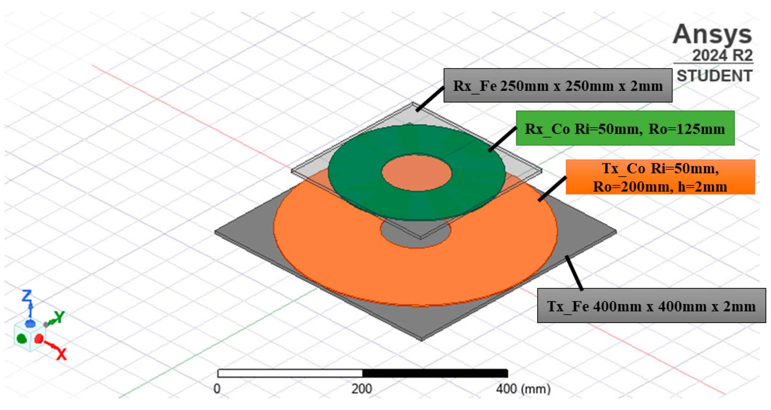
2.1. Geometry Structure Design

DDC power pads are chosen for their design as they offer superior electromagnetic characteristics and greater tolerance for misalignment compared to traditional circular DD pads. The DDC configuration allows for various coil designs to enhance charging efficiency and adaptability in different environments, ensuring compatibility and safety in automotive applications. The power pad has two coils: one is a receiver coil (RX) and the other is a transmitter coil (TX). There are 19 turns both in the TX and RX. The 3D design with proper dimensions and material of the respective coils is given in Figure 1. The given dimensions describe the components of a wireless power transfer system. The RX (receiver) coil has an inner radius (Ri) of 50 mm, an outer radius (Ro) of 125 mm, and a thickness (h) of 0.5 mm, while the TX (transmitter) coil has an inner radius (Ri) of 50 mm, an outer radius (Ro) of 200 mm, and the same thickness (h) of 0.5 mm. Both the TX and RX are equipped with ferrite cores (RX_Fe) that measure 250 mm by 250 mm with a thickness of 2 mm. (TX_Fe) surrounds both components, each measuring 400 mm by 400 mm with a thickness of 2 mm. The following dimensions are given in Table 1.
The self-inductance, coupling coefficient, and Ac resistance are 150 μH, 0.26 k, and 0.1 μΩ, respectively. In this study, there were two designs used with varying thicknesses: 2 mm and 0.5 mm. In Figure 1, the 3D design with a 0.5 mm thick plate is shown.

2.2. Finite Element Analysis (FEA) Tools

The 3D design was carried out using Ansys 2024 R2 (student version) software. Ansys is used for WPT systems to simulate and optimize the electromagnetic fields, coupling efficiency, and power transfer performance. It enables the precise modeling of coil geometries, materials, and operating conditions, helping engineers analyze factors like mutual inductance, resonance, and power losses. By providing detailed insights into electromagnetic behavior, thermal effects, and system efficiency, Ansys allows for the design and validation of WPT systems without the need for extensive physical prototyping, improving performance, reducing costs, and ensuring reliability in real-world applications.
A 15 kW wireless power transfer system is developed for electric vehicle battery charging, featuring high-frequency operation and a large air gap. Advanced co-simulations are conducted using ANSYS Maxwell (ELECTRONICS_STUDENT_2024R2) and Simplorer software to ensure precise design and performance evaluation. This modern solution aims to address the growing demand for efficient and seamless energy transfer in electric mobility applications [21].
The necessary WPT simulations were carried out by following the circuit diagram, as shown in Figure 2, which was generated by using Simplorer. Simplorer is used to calculate the efficiency of wireless power transfer systems because it accurately models complicated electrical, magnetic, and mechanical interactions. It offers system-level simulations, which allow for precise performance and efficiency assessments. The circuit diagram represents a WPT system consisting of a transmitter (Tx) and receiver (Rx) circuit. The transmitter includes a voltage source (E1), capacitors (C1), resistors (R1, R2), and the transmitting coil (Tx_Coil), while the receiver features the receiving coil (Rx_Coil), capacitors (C2), resistors (R3, R4), and load resistance (RL). Wattmeters (WM1 to WM4) are positioned at key points to measure power at different stages. The Tx and Rx coils enable inductive coupling for energy transfer between the circuits.

3. Performance Evaluation

Simulating the power pad allowed us to assess its functionality. The standard design criteria found in the literature were used to validate the simulation result through comparison. In the wireless charging system, a higher coupling coefficient (k), which ranges from 0 to 1, signifies better coupling and improved power transfer efficiency [37]. The coils experienced two types of misalignments: vertical and horizontal. The evaluation of the electromagnetic properties, coupling coefficient, and efficiency of the proposed power pad was conducted by varying the frequency between 85 kHz and 100 kHz. In this study, vertical misalignments ranging from 0 to 100 mm and horizontal misalignments from 100 to 250 mm were taken into account for the power pad coils.
The efficiency of the coil was determined by considering a few parameters. The necessary parameter was taken according to Equation (1). The coils’ efficiency is computed as follows when C2 is linked in series with L2, regardless of how L1 and C1 are coupled [38]:
η c o i l = 1 1 + r 2 R L + r 1 R L × ( 1 + r 2 R L ) 2 + ( ω L 2 1 / ω C 2 R L ) 2 ( ω M / R L ) 2
where the receiver coil’s self-inductance, resonant capacitor, and equivalent series resistance (ESR) are represented by the values L2, r2, and C2; the equivalent load resistance is denoted by RL; and M is the mutual inductance between the transmitter and receiver coils.
The resonance frequency of the WPT system can be determined by the condition when the reactance of the inductive and capacitive components cancels each other out. This is when the system achieves resonance, typically given by the following formula:
f 0 = 1 2 π L 2 C 2
where
L2 = The inductance of the receiver coil;
C2 = The resonant capacitance.

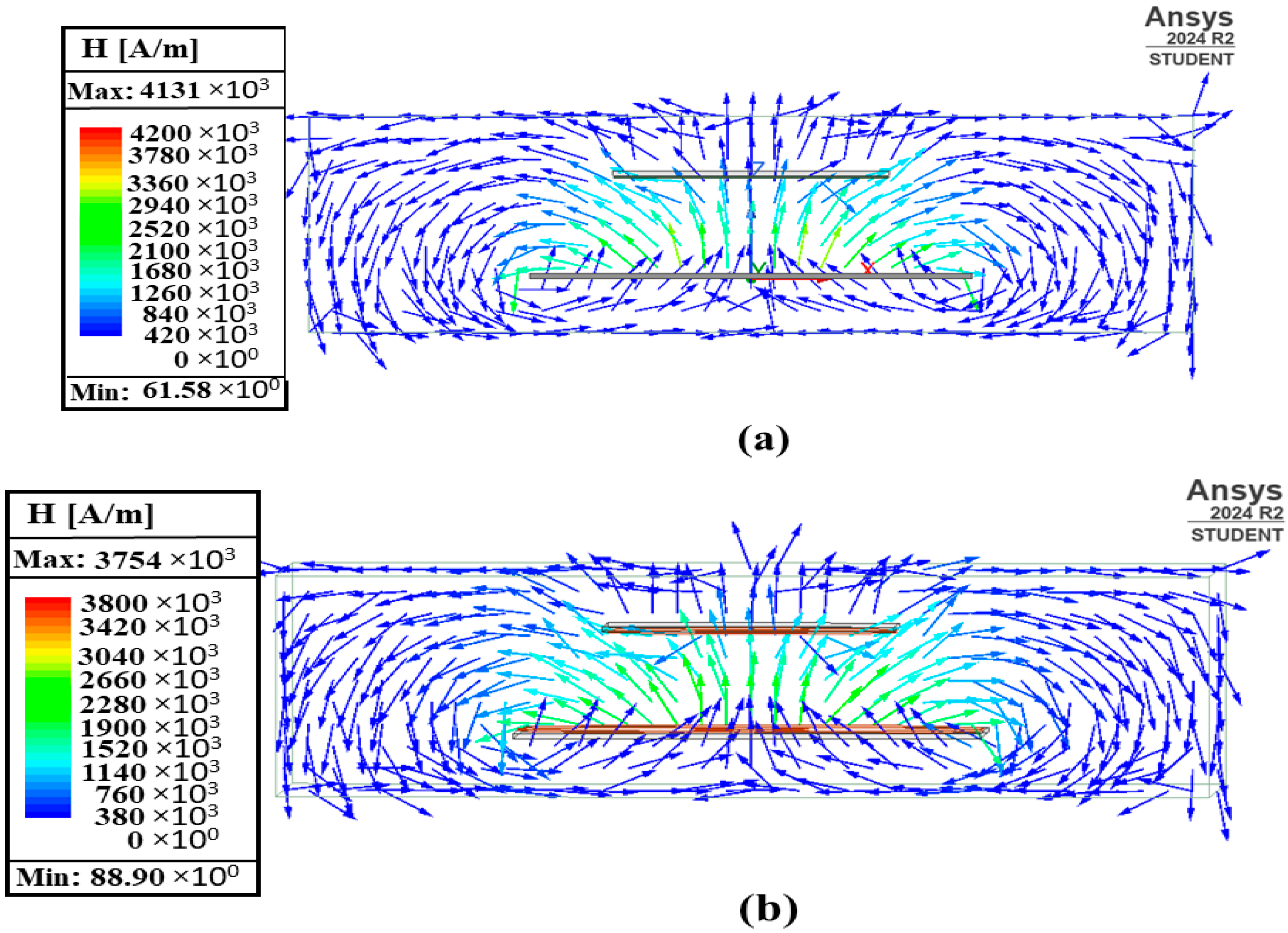
3.1. Electromagnetic Properties

The electromagnetic properties of a power pad were analyzed using Ansys Maxwell 3D, with simulations providing values for magnetic flux density (B) and magnetic field intensity (H), as depicted in Figure 3 and Figure 4. The results revealed a maximum magnetic flux density of 23,700.13 μT for a 0.5 mm thick pad and 24,211.15 μT for a 2 mm thick pad. Correspondingly, the maximum magnetic field had an intensity of 4.13 × 10⁶ A/m for the 0.5 mm thickness and 3.75 × 10⁶ A/m for the 2 mm thickness. These findings indicate that both magnetic flux and magnetic field intensity change with the pad’s thickness, decreasing as the thickness reduces. This study suggests that optimal electromagnetic performance occurs when vertical and horizontal misalignments between the ground assembly (GA) and vehicle assembly (VA) are minimized. Misalignment can arise both vertically and horizontally, influenced by the dimensions of the power pads and the vehicle’s ground clearance. Reducing these misalignments improves the efficiency of the energy transfer. This underscores the importance of precise alignment in optimizing the electromagnetic performance of the power pad system, which is crucial for effective wireless power transfer between the GA and VA.

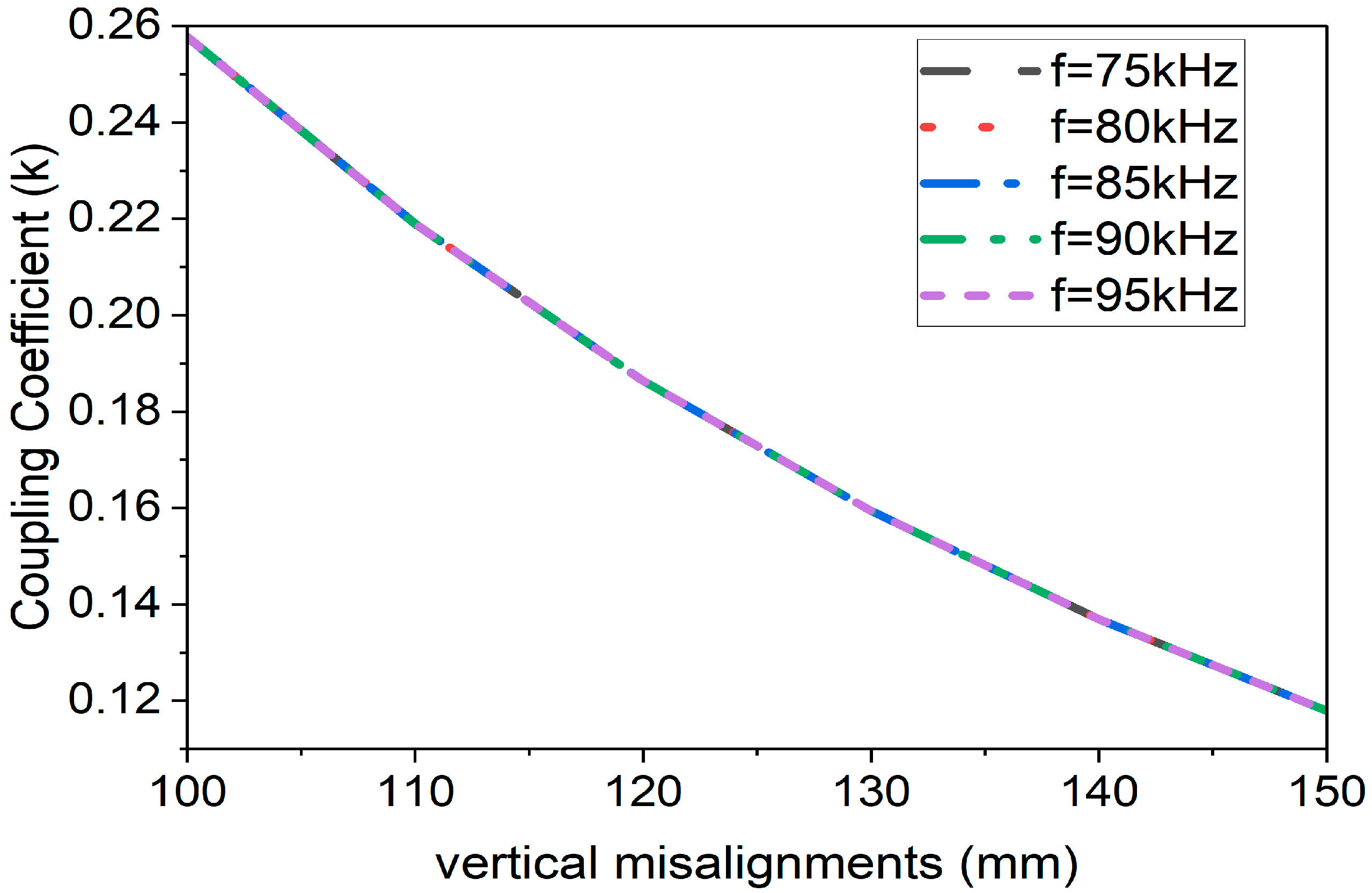
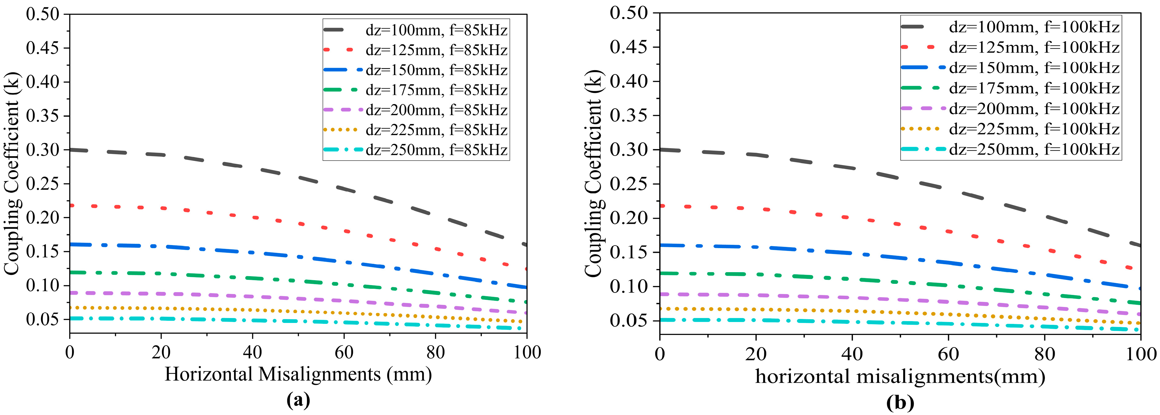
3.2. Coupling Coefficient (k)

The coupling coefficients for various vertical awry were obtained, and the simulation results are illustrated in Figure 5. The coupling coefficient varied with the variation in the misalignments. The simulation was conducted by changing the frequency to 75 kHz and 95 kHz, and the step size was 1 kHz and the value was 0.26 k for a 2 mm thickness coil. From the simulation result, it was observed that the coupling coefficient (k) was not changed by changing frequency, and the same coupling coefficient was obtained for different frequencies. The adaptive frequency was obtained in 85 kHz.
A similar result was obtained for horizontal misalignments, which are shown in Figure 6. The horizontal misalignment ranged from 100 to 250 mm. The maximum coupling coefficient was obtained for 100 mm horizontal misalignment, and the value was 0.30 k for 0.5 mm thickness coil. A different coupling coefficient was observed between the 100 mm vertical and 250 mm horizontal misalignments; both were the lowest values of the respective misalignments. In this scenario, the coupling coefficient for various horizontal misalignments is significantly higher for the proposed DDC power pad than for the circular and DD power pads [39].

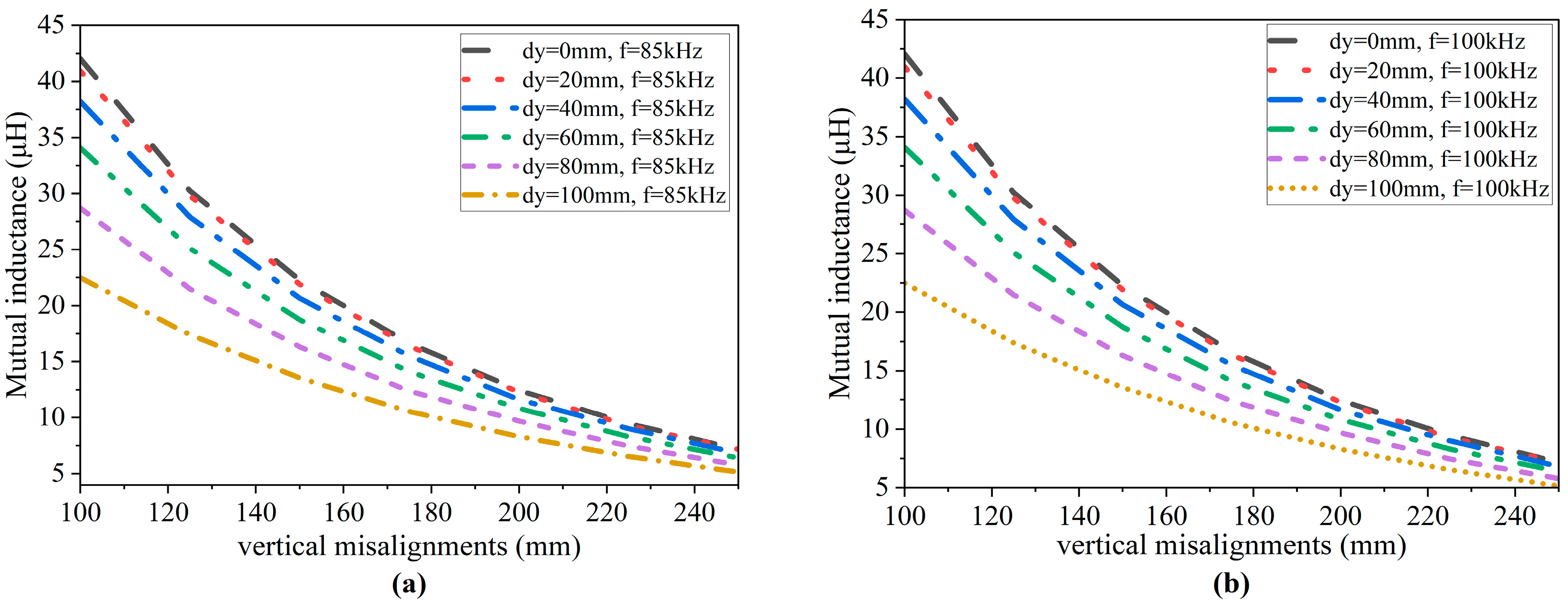
3.3. Mutual Inductance
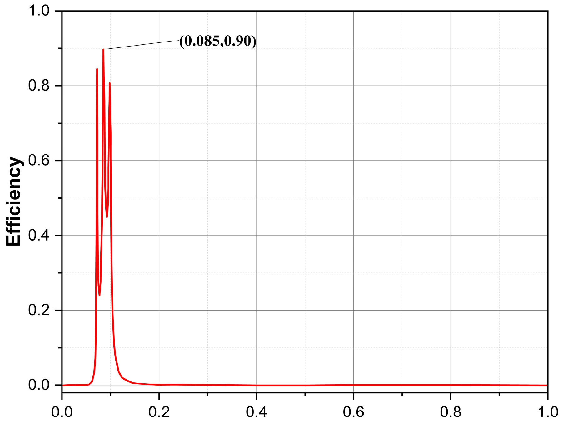
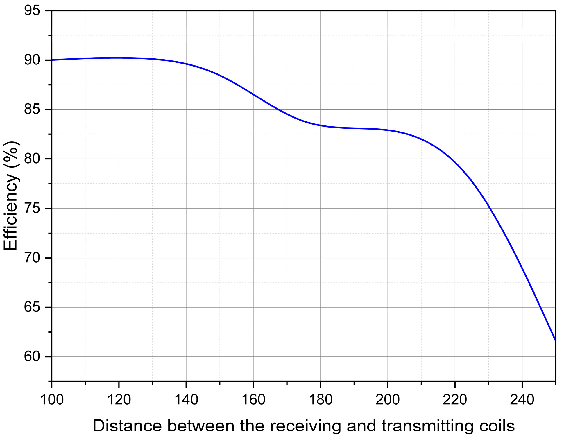
Ansys Maxwell 3D was used for the mutual inductance of the power pads, which was evaluated under 85 kHz and 100 kHz for both the vertical and horizontal misalignments. In vertical misalignments, maximum mutual inductance was observed for 0 mm vertical misalignments. The mutual inductance was decreased by increasing vertical misalignments; also, for this case, the values of the mutual inductance were not changed by changing the frequency from 85 kHz to 100 kHz in Figure 7.
For horizontal misalignments, similarly in Figure 8, the mutual inductance was not changed by changing the frequency. The existence of ferrite materials and the shielding effect are not included in the simulation. The mutual inductance and coupling coefficient data demonstrate that DD power pads outperform circular power pads in terms of misalignment tolerance. The proposed DDC power pads still show outstanding electromagnetic performance when both horizontal and vertical misalignments are included [40,41].

3.4. Efficiency

Simplorer software was used to analyze the WPT system’s efficiency. Figure 9 depicts the WPT system’s efficiency curve, which reaches a maximum of 90%. According to the simulation findings, the thickness of the WPT system influences its effectiveness. Thicker or thinner layers might affect the system’s performance, resulting in variances in efficiency. The simulation was run in Ansys 2024 R2 (student version), and the findings may be impacted by the student version’s constraints, such as limited access to sophisticated simulation capabilities or a lower degree of accuracy. Despite these constraints, this analysis provides valuable insights into the relationship between WPT thickness and system efficiency, although further investigation using the full version of the software may yield more accurate and comprehensive results.
Figure 10 illustrates the relationship between efficiency (%) and the distance between the receiving and transmitting coils in a wireless power transfer (WPT) system. The efficiency remains high, close to 90%, when the distance is minimal (around 100 mm). As the distance increases, efficiency gradually decreases, showing a slight decline from 90% to about 85% as the coils move farther apart (approximately 140–200 mm). Beyond this range, a more significant drop in efficiency is observed, especially when the distance exceeds 200 mm. At 240 mm, the efficiency decreases sharply to around 60%.
This trend indicates that the system performs optimally at shorter distances, where the coupling between the coils is stronger. As the distance increases, the coupling weakens, resulting in reduced efficiency. The sharp decline in efficiency beyond a critical distance highlights the system’s limitations in handling greater coil separation. This graph underscores the importance of maintaining optimal coil alignment and distance to ensure efficient power transfer in practical WPT applications.

3.5. Relationship Between Geometry and Performance

In WPT systems, the geometry of the coil plays a crucial role in determining performance. Key factors affecting coil efficiency and effectiveness include coupling coefficient, inductance, resonance frequency, magnetic field distribution, losses, factors, and multi-coil systems. The proposed geometry in this article features a coil thickness of 0.5 mm, which achieves a higher efficiency of 90%, a magnetic field intensity of 4.13 × 10⁶ A/m, and a coupling coefficient of 0.30 k, surpassing the performance of a 2 mm thick coil. Overall, optimizing WPT coil geometry is essential for maximizing efficiency, minimizing losses, and ensuring performance in practical applications.

4. Conclusions

This investigation focused on the design and analysis of a WPT system for electric vehicles (EVs), particularly exploring the performance of a newly developed double-delta circular (DDC) power pad. This research highlighted the significance of power pad geometry, material properties, and misalignment tolerances in optimizing electromagnetic performance and power transfer efficiency. Despite modeling software restrictions, this research also assesses electromagnetic characteristics, coupling, and efficiency, reaching a maximum efficiency of 90%. Using Ansys Maxwell 3D and Simplorer for the simulation, this study evaluated key electromagnetic parameters, such as magnetic flux density, magnetic field intensity, coupling coefficient, mutual inductance, and efficiency under various vertical and horizontal misalignments. It was found that the coupling coefficient remained stable across different frequencies, with optimal performance observed at 85 kHz. Misalignment was shown to reduce the mutual inductance and coupling efficiency, but the DDC power pad demonstrated superior tolerance to misalignment compared to other designs like circular and double-D (DD) power pads. Additionally, shielding methods, such as the use of ferrite materials and aluminum plates, were recommended for mitigating electromagnetic field (EMF) leakage, though further analysis is needed to fully validate their effectiveness. The results also indicated that the system’s thickness impacts efficiency, with thicker power pads yielding higher magnetic field intensity but requiring careful optimization to avoid energy losses. While the student version of Ansys imposed certain limitations in the aspects of simulating a bigger physical model, these findings contribute valuable insights for improving WPT systems, particularly in enhancing charging efficiency, misalignment tolerance, and EMF safety, which are crucial for the advancement of wireless EV charging technologies. As global copper reserves continue to diminish, this model will become increasingly suitable. Future research should focus on validating these findings using unrestricted software to enhance accuracy in modeling complex systems. This includes exploring advanced coil designs, optimizing shielding methods, and conducting comprehensive analyses of misalignment and efficiency under real-world conditions.

Author Contributions

Conceptualization, M.A., Y.L. and M.I.; methodology, M.A. and Y.L.; software, M.A. and M.I.; formal analysis, M.A. and Y.L.; investigation, M.A.; resources, M.A. and M.I.; data curation, M.A.; writing—original draft preparation, M.A.; writing—review and editing, M.A., Y.L. and M.I.; visualization, M.A.; supervision, Y.L.; project administration, M.A. and Y.L.; funding acquisition, Y.L. All authors have read and agreed to the published version of the manuscript.

Funding

This research was funded by the National Natural Science Foundation of China (NSFC) (61875021); Natural Science Foundation of Beijing (2192036); Fundamental Research Funds for the Central Universities; Guangxi Key Laboratory of Wireless Wideband Communication and Signal Processing; and the BUPT Action Plan Project (ZDYY202102-1).

Institutional Review Board Statement

Not applicable.

Informed Consent Statement

Not applicable.

Data Availability Statement

The original contributions presented in this study are included in the article; further inquiries can be directed to the corresponding author.

Conflicts of Interest

The authors declare no conflicts of interest.

References

  1. Zhang, W.; Fang, X.; Sun, C. The alternative path for fossil oil: Electric vehicles or hydrogen fuel cell vehicles? J. Environ. Manag. 2023, 341, 118019. [Google Scholar] [CrossRef]
  2. Parikh, A.; Shah, M.; Prajapati, M. Fuelling the sustainable future: A comparative analysis between battery electrical vehicles (BEV) and fuel cell electrical vehicles (FCEV). Environ. Sci. Pollut. Res. 2023, 30, 57236–57252. [Google Scholar] [CrossRef]
  3. De Wolf, D.; Smeers, Y. Comparison of Battery Electric Vehicles and Fuel Cell Vehicles. World Electr. Veh. J. 2023, 14, 262. [Google Scholar] [CrossRef]
  4. Benalia, N.; Laroussi, K.; Benlaloui, I.; Kouzou, A.; Bensalah, A.-D.; Kennel, R.; Abdelrahem, M. Optimized Power Pads for Charging Electric Vehicles Based on a New Rectangular Spiral Shape Design. Sustainability 2023, 15, 1230. [Google Scholar] [CrossRef]
  5. Gnanavendan, S.; Selvaraj, S.K.; Dev, S.J.; Mahato, K.K.; Swathish, R.S.; Sundaramali, G.; Accouche, O.; Azab, M. Challenges, Solutions and Future Trends in EV-Technology: A Review. IEEE Access 2024, 12, 17242–17260. [Google Scholar] [CrossRef]
  6. Dorel, S.; Osman, M.G.; Strejoiu, C.-V.; Lazaroiu, G. Exploring Optimal Charging Strategies for Off-Grid Solar Photovoltaic Systems: A Comparative Study on Battery Storage Techniques. Batteries 2023, 9, 470. [Google Scholar] [CrossRef]
  7. Waseem, M.; Ahmad, M.; Parveen, A.; Suhaib, M. Battery technologies and functionality of battery management system for EVs: Current status, key challenges, and future prospectives. J. Power Sources 2023, 580, 233349. [Google Scholar] [CrossRef]
  8. Habib, A.K.M.A.; Hasan, M.K.; Issa, G.F.; Singh, D.; Islam, S.; Ghazal, T.M. Lithium-Ion Battery Management System for Electric Vehicles: Constraints, Challenges, and Recommendations. Batteries 2023, 9, 152. [Google Scholar] [CrossRef]
  9. Zhang, Z.; Pang, H.; Georgiadis, A.; Cecati, C. Wireless Power Transfer—An Overview. IEEE Trans. Ind. Electron. 2019, 66, 1044–1058. [Google Scholar] [CrossRef]
  10. Report on User Centric EV Charging Infrastructure—INCIT-EV Website. (n.d.). Available online: https://www.incit-ev.eu/report-on-user-centric-ev-charging-infrastructure/ (accessed on 3 December 2024).
  11. Palani, G.; Sengamalai, U. A critical review on inductive wireless power transfer charging system in electric vehicle. Energy Storage 2023, 5, e407. [Google Scholar] [CrossRef]
  12. Zhang, Y.; Wang, W.; Wu, X.; Lei, Y.; Cao, J.; Bowen, C.; Bader, S.; Yang, B. A comprehensive review on self-powered smart bearings. Renew. Sustain. Energy Rev. 2023, 183, 113446. [Google Scholar] [CrossRef]
  13. Li, Y.; Zhang, S.; Cheng, Z. Double-coil dynamic shielding technology for wireless power transmission in electric vehicles. Energies 2021, 14, 5271. [Google Scholar] [CrossRef]
  14. De Santis, V.; Giaccone, L.; Freschi, F. Chassis influence on the exposure assessment of a compact EV during WPT re-charging operations. Magnetochemistry 2021, 7, 25. [Google Scholar] [CrossRef]
  15. The Society of Automobile Engineers. SAE J2954: Wireless Power Transfer for Light-duty Plug-in/electric Vehicles and Alignment Methodology. In Surface Vehicle Information Report; SAE International: Warrendale, PA, USA, 2019. [Google Scholar]
  16. Budhia, M.; Covic, G.A.; Boys, J.T. Design and optimization of Circular Magnetic Structures for Lumped Inductive Power Transfer Systems. IEEE Trans. Power Electron. 2011, 26, 3096–3108. [Google Scholar] [CrossRef]
  17. Alam Chowdhury, M.S.; Liang, X. Design and Performance Evaluation for a New Power Pad in Electric Vehicles Wireless Charging Systems. Can. J. Electr. Comput. Eng. 2020, 43, 146–156. [Google Scholar] [CrossRef]
  18. Yang, Y.; El Baghdadi, M.; Lan, Y.; Benomar, Y.; Van Mierlo, J.; Hegazy, O. Design methodology, modeling, and comparative study of wireless power transfer systems for electric vehicles. Energies 2018, 11, 1716. [Google Scholar] [CrossRef]
  19. Song, K.; Yang, G.; Guo, Y.; Lan, Y.; Dong, S.; Jiang, J.; Zhu, C. Design of DD Coil with High Misalignment Tolerance and Low EMF Emissions for Wireless Electric Vehicle Charging Systems. IEEE Trans. Power Electron. 2020, 35, 9034–9045. [Google Scholar] [CrossRef]
  20. Kuzey, S.; Balci, S.; Altin, N. Design and analysis of a wireless power transfer system with alignment errors for electrical vehicle applications. Int. J. Hydrogen Energy 2017, 42, 17928–17939. [Google Scholar] [CrossRef]
  21. Ahmed, M.M.; Enany, M.A.; Shaier, A.A.; Bawayan, H.M.; Hussien, S.A. An Extensive Overview of Inductive Charging Technologies for Stationary and In-Motion Electric Vehicles. IEEE Access 2024, 12, 69875–69894. [Google Scholar] [CrossRef]
  22. Shafiq, Z.; Li, T.; Xia, J.; Li, S.; Yang, X.; Zhao, Y. Addressing EMI and EMF Challenges in EV Wireless Charging with the Alternating Voltage Phase Coil. Actuators 2024, 13, 324. [Google Scholar] [CrossRef]
  23. Dimitriadou, K.; Rigogiannis, N.; Fountoukidis, S.; Kotarela, F.; Kyritsis, A.; Papanikolaou, N. Current Trends in Electric Vehicle Charging Infrastructure; Opportunities and Challenges in Wireless Charging Integration. Energies 2023, 16, 2057. [Google Scholar] [CrossRef]
  24. Song, K.; Lan, Y.; Zhang, X.; Jiang, J.; Sun, C.; Yang, G.; Yang, F.; Lan, H. A Review on Interoperability of Wireless Charging Systems for Electric Vehicles. Energies 2023, 16, 1653. [Google Scholar] [CrossRef]
  25. Sifatul, M.; Chowdhury, A.; Liang, X. Design of a Ferrite-Less Power Pad for Wireless Charging Systems of Electric Vehicles. In Proceedings of the 2019 IEEE Canadian Conference of Electrical and Computer Engineering (CCECE), Edmonton, AB, Canada, 5–8 May 2019. [Google Scholar]
  26. Ahmad, A.; Alam, M.S.; Mohamed, A.A.S. Design and Interoperability Analysis of Quadruple Pad Structure for Electric Vehicle Wireless Charging Application. IEEE Trans. Transp. Electrif. 2019, 5, 934–945. [Google Scholar] [CrossRef]
  27. Budhia, M.; Boys, J.T.; Covic, G.A.; Huang, C.-Y. Development of a single-sided flux magnetic coupler for electric vehicle IPT charging systems. IEEE Trans. Ind. Electron. 2013, 60, 318–328. [Google Scholar] [CrossRef]
  28. Sulejmani, E.; Beltle, M.; Tenbohlen, S. EMC of Inductive Automotive Charging Systems According to Standard SAE J2954. Vehicles 2023, 5, 1532–1552. [Google Scholar] [CrossRef]
  29. Ghazizadeh, S.; Mekhilef, S.; Seyedmahmoudian, M.; Chandran, J.; Stojcevski, A. Performance Evaluation of Coil Design in Inductive Power Transfer for Electric Vehicles. IEEE Access 2024, 12, 108201–108223. [Google Scholar] [CrossRef]
  30. Vivarelli, C.; Censi, F.; Calcagnini, G.; Freschi, F.; Giaccone, L.; Canova, A.; Mattei, E. Electromagnetic Immunity of Pacemakers and Implantable Defibrillators to Wireless Power Transfer Systems for Automotive: A Provocative Study. IEEE Trans. Electromagn. Compat. 2024, 66, 97–107. [Google Scholar] [CrossRef]
  31. Zaheer, A.; Covic, G.A.; Kacprzak, D. A bipolar pad in a 10-kHz 300-W distributed IPT system for AGV applications. IEEE Trans. Ind. Electron. 2014, 61, 3288–3301. [Google Scholar] [CrossRef]
  32. Soleimani, J.; Kurt, G.K. High-power radio frequency wireless energy transfer system: Comprehensive survey on design challenges. IET Wirel. Sens. Syst. 2024, 14, 248–264. [Google Scholar] [CrossRef]
  33. Laha, A.; Kalathy, A.; Pahlevani, M.; Jain, P. A Comprehensive Review on Wireless Power Transfer Systems for Charging Portable Electronics. Eng 2023, 4, 1023–1057. [Google Scholar] [CrossRef]
  34. Mishra, K.; Kushawaha, A.; Chaurasia, N.; Kumar, S.; Singh, G.K.; Shahid, M. Development of Witricity Based Wireless Power Transmission System. Lect. Notes Electr. Eng. 2024, 1086, 619–634. [Google Scholar] [CrossRef]
  35. Alabsi, A.; Hawbani, A.; Wang, X.; Al-Dubai, A.; Hu, J.; Aziz, S.A.; Kumar, S.; Zhao, L.; Shvetsov, A.V.; Alsamhi, S.H. Wireless power transfer technologies, applications, and future trends: A review. IEEE Trans. Sustain. Comput. 2024, 1–18. [Google Scholar] [CrossRef]
  36. Patil, D.; McDonough, M.K.; Miller, J.M.; Fahimi, B.; Balsara, P.T. Wireless Power Transfer for Vehicular Applications: Overview and Challenges. IEEE Trans. Transp. Electrif. 2017, 4, 3–37. [Google Scholar] [CrossRef]
  37. Fahrbach, F.O.; Simon, P.; Rohrbach, A. Microscopy with self-reconstructing beams. Nat. Photonics 2010, 4, 780–785. [Google Scholar] [CrossRef]
  38. Lu, M.; Ngo, K.D.T. Pareto Fronts for Coils’ Efficiency Versus Stray Magnetic Field in Inductive Power Transfer. In Proceedings of the 2016 IEEE PELS Workshop on Emerging Technologies: Wireless Power Transfer (WoW), Knoxville, TN, USA, 4–6 October 2016. [Google Scholar]
  39. Xue, H.; Wu, X.; Cui, X.; Chang, M.; Liu, H.; Li, L.; Cui, T.J. Multitarget Wireless Power Transfer System Using Metasurface for Quasi-Bessel Beams with Large Half Power Beam Length. IEEE Trans. Microw. Theory Tech. 2022, 70, 4449–4462. [Google Scholar] [CrossRef]
  40. Kadem, K.; Bensetti, M.; Le Bihan, Y.; Labouré, E.; Debbou, M. Optimal coupler topology for dynamic wireless power transfer for electric vehicle. Energies 2021, 14, 3983. [Google Scholar] [CrossRef]
  41. Arduino, A.; Bottauscio, O.; Chiampi, M.; Giaccone, L.; Liorni, I.; Kuster, N.; Zilberti, L.; Zucca, M. Accuracy Assessment of Numerical Dosimetry for the Evaluation of Human Exposure to Electric Vehicle Inductive Charging Systems. IEEE Trans. Electromagn. Compat. 2020, 62, 1939–1950. [Google Scholar] [CrossRef]
Figure 1. Prospective 3D-designed power pad created in Ansys Maxwell 3D (2024 R2).
Energies 18 00244 g001
Figure 2. Circuit diagram for simulation.
Energies 18 00244 g002
Figure 3. Electromagnetic properties: (a) magnetic flux density (B) for 0.5 mm thickness; (b) magnetic flux density (B) for power pads for 2 mm thickness.
Energies 18 00244 g003
Figure 4. Electromagnetic properties: (a) magnetic field intensity (H) for 0.5 mm thickness; (b) magnetic field intensity (H) for 2 mm thickness.
Energies 18 00244 g004
Figure 5. Variation of 2 mm coil thickness coupling coefficient (k) with varying misalignments.
Energies 18 00244 g005
Figure 6. Variation of 0.5 mm coil thickness coupling coefficient (k) with varying horizontal misalignments when frequency was (a) 85 kHz and (b) 100 kHz.
Energies 18 00244 g006
Figure 7. Mutual inductance (μH) with varying vertical misalignments when frequency was (a) 85 kHz and (b) 100 kHz.
Energies 18 00244 g007
Figure 8. Mutual inductance (μH) with varying horizontal misalignments when frequency was (a) 85 kHz and (b) 100 kHz.
Energies 18 00244 g008
Figure 9. Power transfer efficiency curve of the WPT.
Energies 18 00244 g009
Figure 10. Power transfer efficiency curve with variation in distance between the receiving and transmitting coils of the WPT.
Energies 18 00244 g010
Table 1. Parameters for design of IPT coils.
Materials Inner DimensionOuter Dimension Hight
RX_Coil50 mm125 mm0.5 mm
TX_Coil50 mm200 mm0.5 mm
RX_Fe250 mm250 mm2 mm
TX_Fe400 mm400 mm2 mm
Disclaimer/Publisher’s Note: The statements, opinions and data contained in all publications are solely those of the individual author(s) and contributor(s) and not of MDPI and/or the editor(s). MDPI and/or the editor(s) disclaim responsibility for any injury to people or property resulting from any ideas, methods, instructions or products referred to in the content.

