Abstract
This manuscript aims to increase the utilization of solar energy, which is both environmentally friendly and easily accessible, to satisfy the energy needs of developing countries. In order to achieve this goal, maximum power generation should be provided from photovoltaic panels. Several maximum power point tracking (MPPT) methods are utilized for maximum power generation in photovoltaic panel systems under different weather conditions. In this paper, a novel intelligent hybrid fuzzy logic-controlled maximum power point tracking algorithm founded on the perturb and observe (PO) algorithm is presented. The proposed fuzzy logic controller algorithm and the incremental conductivity maximum power point tracking algorithm were simulated in a MATLAB(2018b version)/Simulink environment and evaluated by comparing the results. Four Sharp ND-F4Q295 solar panels, two in series and two in parallel, were used for the simulation. In this study, the voltage ripple of the proposed hybrid method was measured at 1% compared to the classical incremental conductivity method, while it was 8.6% in the IncCon method. Similarly, the current ripple was 1.08% in the proposed hybrid FLC method, while the current ripple was 9.27% in the IncCon method. It is observed that the proposed smart method stabilizes the system voltage faster, at 25 ms, in the event of sudden weather changes.
1. Introduction
Energy is a critical factor in a country’s social and economic development, with rising demands driven by technological progress. In developing countries such as Turkey, most energy production relies on non-renewable primary sources. As fossil fuel usage declines, environmental pollution drives the search for alternative energy sources. The European Union (EU) has established climate and energy targets with the objective of reducing greenhouse gas emissions, enhancing energy efficiency, and expanding the utilization of renewable energy sources. By 2020, the EU aimed for a 20% reduction in emissions and 20% renewable energy in production. If the current renewable energy adoption rate continues, the EU expects to achieve a 27% renewable energy share by 2030 [1]. Renewable sources such as wind, solar, and hydroelectric energy offer reliable, environmentally friendly, and sustainable energy production [2]. A photovoltaic (PV) system, which converts solar energy into electrical energy, represents one of the most effective renewable energy technologies due to its environmentally friendly, clean, and maintenance-free nature [3]. Nonetheless, PV systems also have disadvantages, such as high initial installation costs and low efficiency of the panels. In order to overcome this, it is recommended that governments provide incentives for green energy with an increase in panel production [4]. On the other hand, since it is a modular system for off-grid and remote locations in islanded mode, it can generate electricity at an affordable cost. In recent years, with the installation of large PV systems, grid-connected systems have become the most important source of electrical energy generation.
The maximum power point tracking (MPPT) process is an effective method for optimizing the efficiency of PV systems. MPPT control algorithms are important because they take into account the nonlinear power–voltage (P-V) relationship of PV panels to generate maximum power. MPPT algorithms are employed for the regulation of the duty cycle of a DC-DC boost or buck converter that is connected to the PV system [5]. The most widespread MPPT algorithms used in the literature are the Hill Climbing or Perturb and Observe (PO), Incremental Conductance (IncCon), Fractional Open-Circuit Voltage (FOCV), Fractional Short-Circuit Current (FSCC), Fuzzy Logic Control (FLC), and Neural Network (NN) algorithms [6]. PO and IncCon MPPT algorithms are mostly used due to their simple form and easy applicability. In both of these methods, maximum power is obtained by measuring the PV panel’s current and voltage using two sensors. The power-tracking PO method performance is slow, and high oscillations occur around the MPPT [7,8].
This paper will present in detail a novel, intelligent and hybrid technique for MPPT that makes use of the PO algorithm. This paper presents an FLC design and model for MPPT for PV systems, using fuzzy logic’s ability to express a problem using language [9].
By designing a DC-DC buck–boost converter and comparing the fuzzy logic MPPT method with the classical POMPPT method, it was shown that the new MPPT-based FLC method provides higher efficiency and performance than PO [10]. An adaptive fuzzy logic controller (AFLC) algorithm has been proposed to operate the PV system using the MPPT method to improve its steady-state performance and robustness and effectively control the sudden load variations connected to a buck–boost converter [11]. An adaptive PO–fuzzy algorithm is proposed for MPPT control in a DC-DC boost converter by integrating the advantages of both PO and fuzzy logic techniques [12]. The mathematical model of a photovoltaic (PV) panel, which highlights the primary innovation, has been validated through the utilization of diverse test scenarios incorporating temperature and solar irradiance variables. This approach enables the assessment of a fuzzy controller’s efficacy in monitoring the maximum power point of a PV system [13].
Reference [14] used a hybrid method to partition the entire search space of maximum power point (MPP) into three regions to support the classical PO algorithm to find the global MPP under partial shades and proposed an FLC to determine the GMPPs region. In this paper, a method that perceives the output circuit voltage and short-circuit current for optimal control with a fuzzy controller and uses these two parameters has been introduced [15]. To prove the effectiveness of the MPPT algorithm with FLC, an optimum duty cycle was created by controlling the modeled DC-DC converter connected to the PV array [16]. For the maximum power generation from the PV system with the SEPIC converter, the effectiveness of the MPPT algorithms using PO, incremental conductivity (IC), and FLC are compared, and the efficiency and MPPT time of FLC are shown to be more favorable than those of the other two techniques [17]. An enhancement has been made to a hybrid FLC MPPT control algorithm by merging the fuzzy-based PO algorithm with the fuzzy-based FSCC algorithm, demonstrating through analysis that said hybrid algorithm generates superior dynamic performance [18]. For MPPT in PV systems, sliding mode controller (SMC) and FLC techniques have been compared that have been simulated, and it has been mentioned that the FLC algorithm reacts slower than the SMC algorithm and the SMC has a more robust control capability than the FLC algorithm [19]. In [20], it is stated that the FLC MPPT method improves efficiency, reduces cost, reduces losses, and increases battery life by the fact that the boost converter connected to the PV panel responds quickly under variable environmental conditions and is unaffected by any alterations in the circuit parameters.
In [21], the FLC method of the MPPT of the PV system is compared with the PO and IC methods under different weather conditions. The proposed FLC technique is demonstrated to be more efficient than conventional methods by simulation and experimental results. By integrating PO with fuzzy logic, it is focused on improving the MPPT performance for PV systems by using the control method called ‘Fuzzy Distortion’. The simulation run in MATLAB/Simulink is designed with a classical DC-DC Boost structure. The proposed method has been demonstrated to increase tracking speed, optimize MPP detection, and reduce output power fluctuations [22]. This paper presents the design and modelling of a fuzzy controller for maximum power point (MPP) monitoring of a 65-watt photovoltaic (PV) system with a buck converter circuit. The classical PO method and the developed fuzzy logic methods are compared. It is shown that the fuzzy controller performs better in the event of sudden temperature changes. The proposed method shows that it enables a battery in an off-grid PV system to provide the highest power [23]. PO MPPT control system is widely used in applications due to its simplicity and easy control. However, it has a disadvantage: oscillations occur near the MPP point. This leads to energy losses and system instability in the PV system [24]. One solution to improve the response time of the conventional PO method is to solve the constant disturbance problems surrounding the MPP by using input defuzzification and defuzzification removal processes. This method generates new output values and set points during a disturbance [25]. In order to achieve enhanced outcomes from photovoltaic (PV) systems, it is necessary to integrate conventional techniques with alternative methodologies for the detection of the maximum power point (MPP) under conditions of partial shading. One of the MPPT intelligent computing methods, FLC, is successful in monitoring MPP but needs more memory to implement fuzzy logic rules [26,27].
The shortcomings of these methods are that they create difficulties in real-time applications due to high computational complexity, some methods (e.g., FLC) cannot adapt to rapid environmental changes with slow response times, measurement noise causes accuracy losses in derivative-based error calculations, there are high memory and resource requirements, and the classical PO method causes energy loss and system instability due to oscillations close to the MPP. However, the combination of PO-based fuzzy logic and Incremental Conductance (IC) algorithms used as the proposed method improves MPPT performance in PV systems. This method accelerates real-time tracking by reducing computational complexity, provides faster adaptation to environmental changes, increases resilience to noise, and strengthens system stability by reducing oscillations. In addition, it increases efficiency by optimizing memory and resource usage. In this way, more accurate, stable, and fast MPP tracking is provided.
Research on optimization of MPPT algorithms aims to increase the efficiency of PV systems and to adapt rapidly to environmental changes. However, classical algorithms such as PO and Incremental Conductance have shortcomings such as oscillations, computational complexity, and sensitivity to noise. Although FLC-based methods are successful in adapting to environmental conditions, they face difficulties such as high memory and processing power requirements and sensitivity to noise. Hybrid studies conducted to overcome these shortcomings offer potential solutions such as the combination of algorithms such as PO and IC or the combination of FLC and IC to increase system stability, reduce oscillations, and achieve faster response times. Such hybrid methods provide significant progress in increasing the efficiency of MPPT and enabling faster adaptation to environmental changes.
When selecting the input variable, the error e(t) in the FLC-based MPPT technique is generally calculated as dPPV/dVPV or dPPV/dIPV to find the error e(t), and the relative error change Δe(t) is taken as input accordingly [28,29,30].
These input methods increase the computational complexity. Moreover, the derivative operation can cause a large amount of error from only a small amount of measurement noise. In the proposed method, the change in power (ΔPpv) and the change in voltage (ΔVpv) are taken as inputs. In this case, the calculation is simplified and the accuracy is increased. In this study, a hybrid MPPT method is implemented by applying fuzzy logic rules to the widely used PO algorithm. In other words, PO based fuzzy logic MPPT method has been developed.
In this study, FLC and IncCon MPPT methods are simulated and compared in a MATLAB/Simulink environment. Four Sharp ND-F4Q295 PV panels, two of which were serial and two of which were parallel, were used for simulation.
The main contributions of this method are that it provides an optimized MPPT solution to reduce oscillations, increase system stability, and adapt faster to environmental changes by using the combination of PO-based FLC and Incremental Conductance algorithms. The method reduces the high memory and processing power requirements, resulting in lower resource consumption and improving the energy efficiency of solar panel systems. As an innovation, the combination of PO and IC algorithms significantly improves the MPPT performance with fast response, low memory usage, and robustness to noise.
The article is structured as follows: Section 2 describes the detailed operation of the IncCon MPPT algorithm. Section 3 describes the detailed operation of the PO MPPT algorithm. Section 4 describes the FLC algorithm in detail. In Section 5, the proposed FLC algorithm is explained in detail. In Section 6, the simulation results of the proposed FLC algorithm and IncCon MPPT algorithms are compared and analyzed. Finally, the results are presented in Section 7.
2. IncCon MPPT Methods
The MPP in this approach is identified by utilizing the PV panel’s P-V characteristic curve. In this algorithm, the current and voltage values of the PV panel are measured continuously. According to the current measurement and voltage values, the power generated by the PV panel is calculated, as shown in Equation (1).
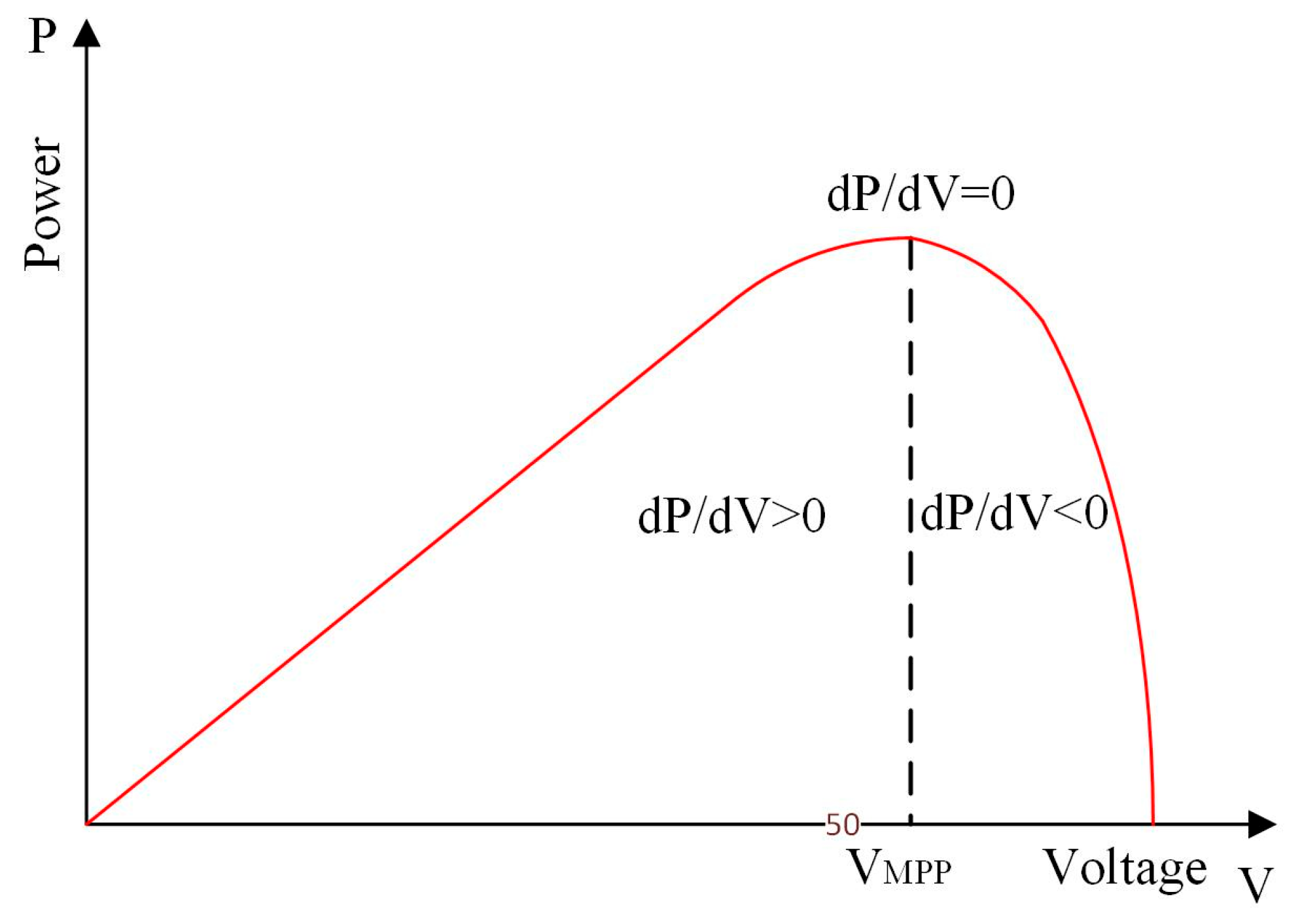
As illustrated in Figure 1, the IncCon MPPT algorithm operates on the principle that the MPP occurs where the ratio of the PV panel’s change in power (ΔP) to the change in voltage (ΔV) is zero (MPP) (ΔP/ΔV = 0). In this method, to determine the change in the power generation of the PV panel and the point where this ratio ΔP/ΔV is zero, the conductivity value (I/V) is used.

Figure 1.
Increasing conductivity on the P-V graph of the PV panel.
The power produced by the panel is calculated as in Equation (1), which provides the formation of this method. If the derivative of the expression in Equation (2) is taken according to the voltage,
If the equation is rewritten due to the fact that at the MPP, the point at which the PV power variation is equal to zero must be dP/dV = 0:
Hence, Equation (5) is obtained.
The PV panel voltage can be quickly adjusted by increasing or decreasing the reference voltage, current, or relative conduction time (D) until the MPP voltage is reached by measuring the incremental and the instantaneous conductance of the array (dI/dV or I/V). The method of Equation (5) is used as an indicator of the process of tracking the maximum power point. When dP/dV is less than zero, decreasing the reference voltage causes dP/dV to tend towards zero; when dP/dV is greater than zero, increasing the reference voltage causes dP/dV to tend towards zero; when dP/dV is equal to zero, no adjustment to the reference voltage is required [23].
In this case, dP/dV = 0, at MPP, dP/dV > 0, to the left of the MPP, dP/dV < 0 is understood to be on the right side of the MPP [31].
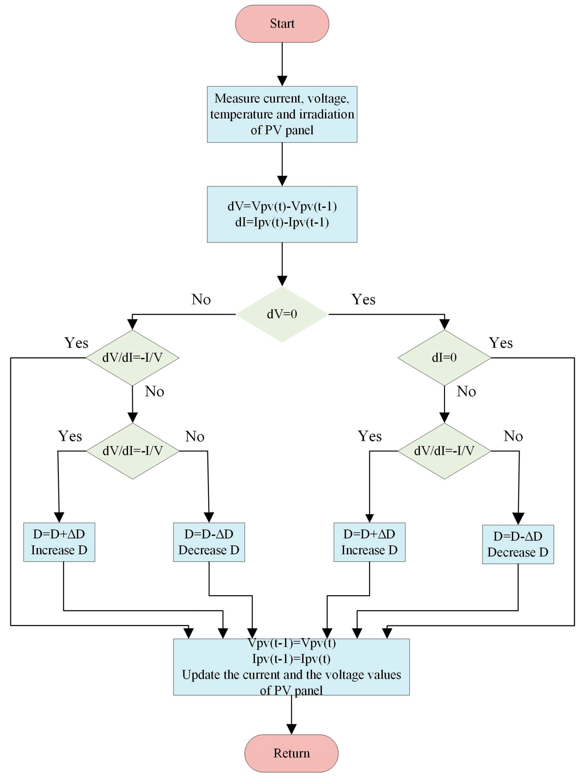
The IncCon algorithm is more complex than the PO algorithm, but it is one of the most widely used methods for variable environmental conditions due to its better tracking of the MPP [32]. The benefits of this approach are that the ripples that occur at the MPP are reduced, and the power loss is less. In addition, it is faster and more durable than the PO algorithm in detecting MPP points against rapidly changing environmental conditions. Figure 2 shows the algorithm flow diagram of the IncCon method [33].
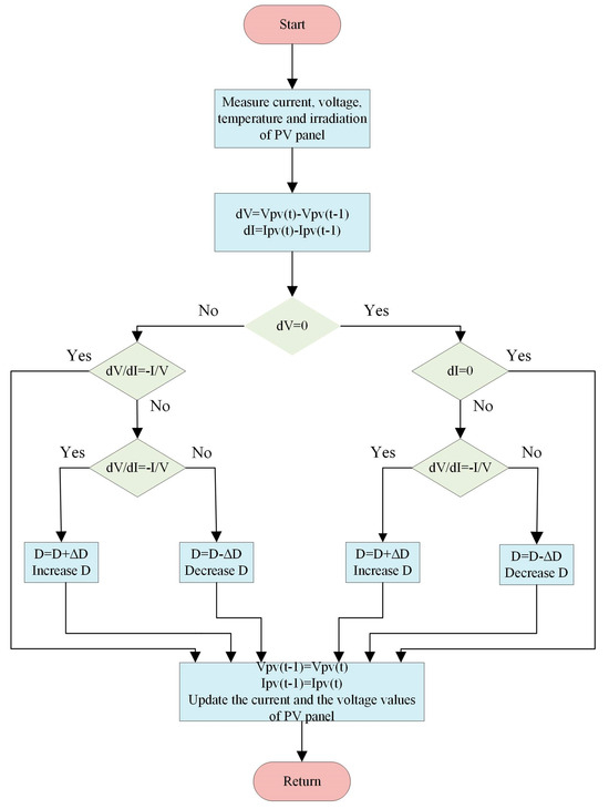
Figure 2.
Flowchart of the IncCon algorithm.
In the presence of a load connected to the photovoltaic (PV) module, the operating point will only coincide with the maximum power point (MPP) in exceptional circumstances. In all other cases, the system will not operate at maximum power. When a load is coupled to the photovoltaic (PV) module, the operating point will coincide with the MPP only in very special cases; in the case of other conditions the system will not function at maximum power.
3. PO MPPT Method
The perturb and observe (PO) method is the most commonly used MPPT technique nowadays [34]. Using Equations (1) and (2), the maximum output power of the PV panel is achieved.
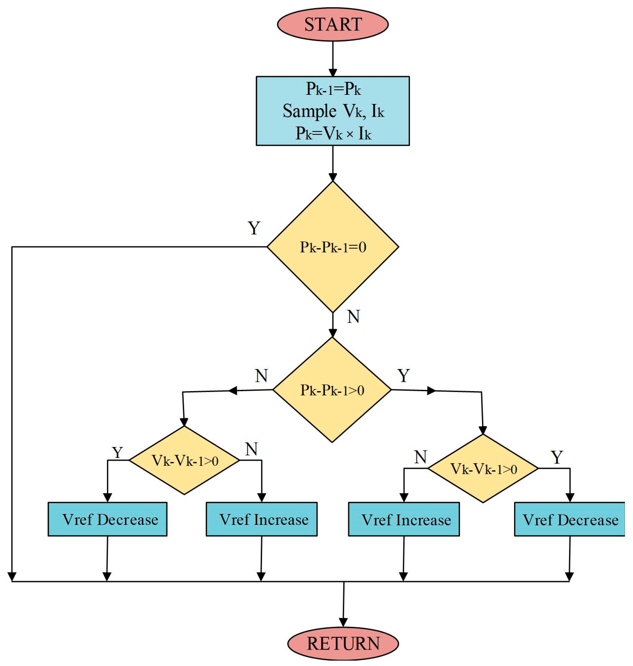
Considering the PO algorithm in Figure 3, the instantaneous voltage and current values of the PV panel are measured, and the instantaneous power value is calculated. It makes it possible to increase the voltage or to reduce it until the point of maximum power is located. The calculation process will be repeated in each switching cycle until the maximum power point is reached, as indicated by ΔP/ΔV = 0. One disadvantage of using the POMPPT algorithm is that the operating point will fluctuate around the MPP in stationary conditions, resulting in a loss of available power [35,36].
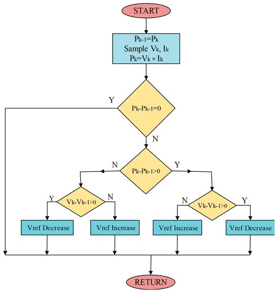
Figure 3.
PO MPPT flowchart [37].
4. Fuzzy Logic-Controlled MPPT Method
The FLC is a widely employed intelligent technique for the implementation of MPPT operations in photovoltaic systems, which are subject to non-linear environmental conditions. Although fuzzy logic has a complex structure, it provides more accurate results in MPPT processes and is more stable in variable weather conditions. The fuzzy logic method has more advantages than other conventional MPPT methods. With these advantages, there is no requirement for a mathematical model to execute the operations. It has the capability to operate with variable inputs. It can cope with nonlinear situations. FL Controllers have a more robust structure than classical controllers [38]. It also has several advantages, such as fast response times and good performance compared with conventional methods, a robust structure, and a simple design [39].
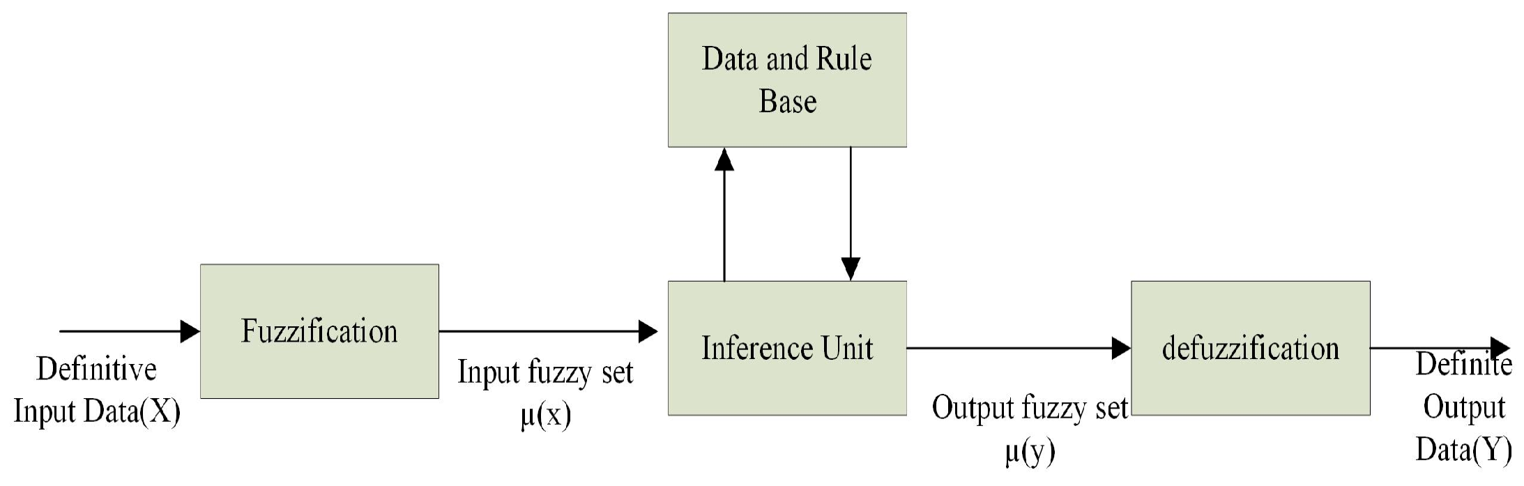
Fuzzy logic deals with ambiguous or imprecise situations, unlike the precise logic of the Boolean theory. In fuzzy logic, a variable is constituted by clusters of values, which are characterized by non-numerical verbal expressions. These may include terms such as SMALL (S), MEDIUM (M), LARGE (L), and so on. This linguistic expression is then numerically represented by fuzzy sets, which are sometimes referred to as fuzzy subsets. In contrast to the 0 and 1 limits of a Boolean set, each fuzzy set is defined by a membership function that varies between 0 and 1. This is in accordance with the principles set out in references [40,41]. Therefore, in the fuzzy logic method, membership functions created for these verbal values are used instead of mathematical modeling. The fundamental structure of a fuzzy controller is shown in Figure 4. The fuzzy logic controller consists of four main sections. These concepts are described as fuzzification, fuzzy inference engine, rule base, and defuzzification.
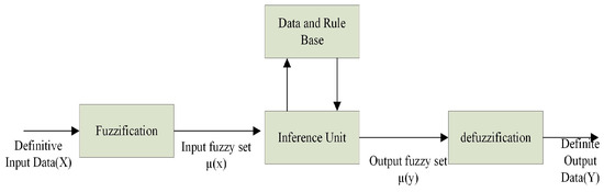
Figure 4.
Fuzzy system [42].
4.1. Fuzzification
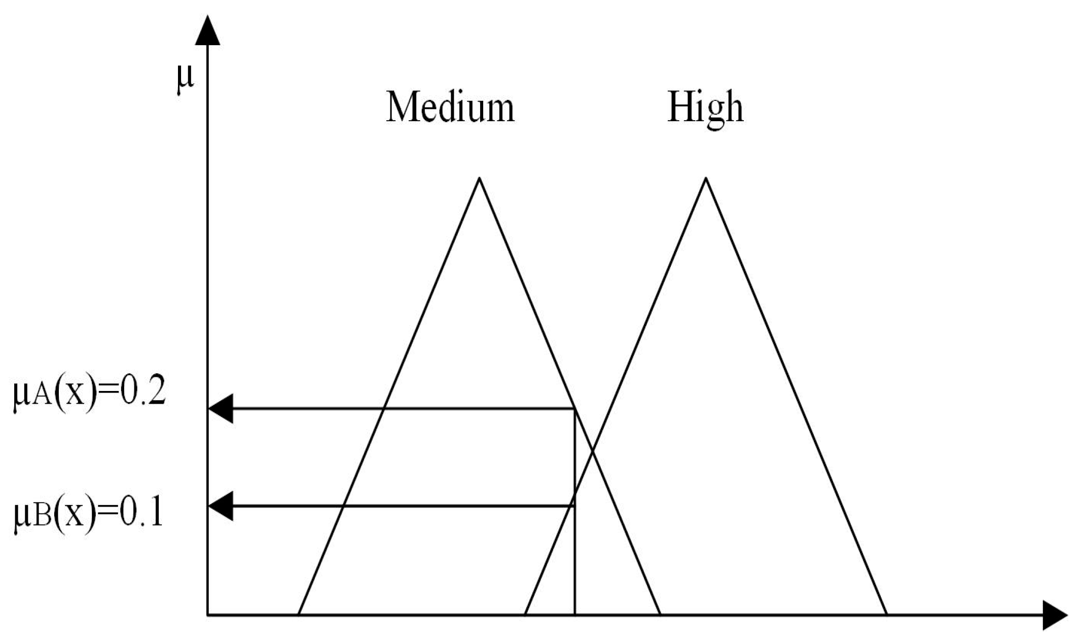
The procedure in question pertains to the conversion of precise real scalar values into non-numeric linguistic values and fuzzy values. Fuzzy values are degree classifications that form sets of membership functions. For this purpose, the measured voltage and current of the PV panels and the calculated variation of the generated power are used as input values for the FLC. Figure 5 shows the transformation of a real value into a fuzzy value. For each input value, the corresponding membership function returns the value µ. The max-min method was employed to extract µ from the triangular type membership function.

Figure 5.
Fuzzification process [43].
4.2. Fuzzy Inference Engine
In the rule base, it is the part that includes the operations that enable the fuzzy system to behave and generate a single output by collecting all the connections between the input and output fuzzy sets in one place. In this section, a rule base is applied to the membership function obtained according to an inference method for the inferences of each rule. Each method basically fulfills the same task, but some methods are preferred over others due to factors such as efficiency and complexity, subject to the parameters of the problem being studied. The most widely used inference methods in fuzzy systems are the Mamdani and Sugeno inference methods. A rule base was applied to the membership function obtained in accordance with the methodology proposed by Mamdani. The resulting rule table is presented in Table 1.

Table 1.
Rule table of fuzzy logic.
4.3. Fuzzy Rule Table
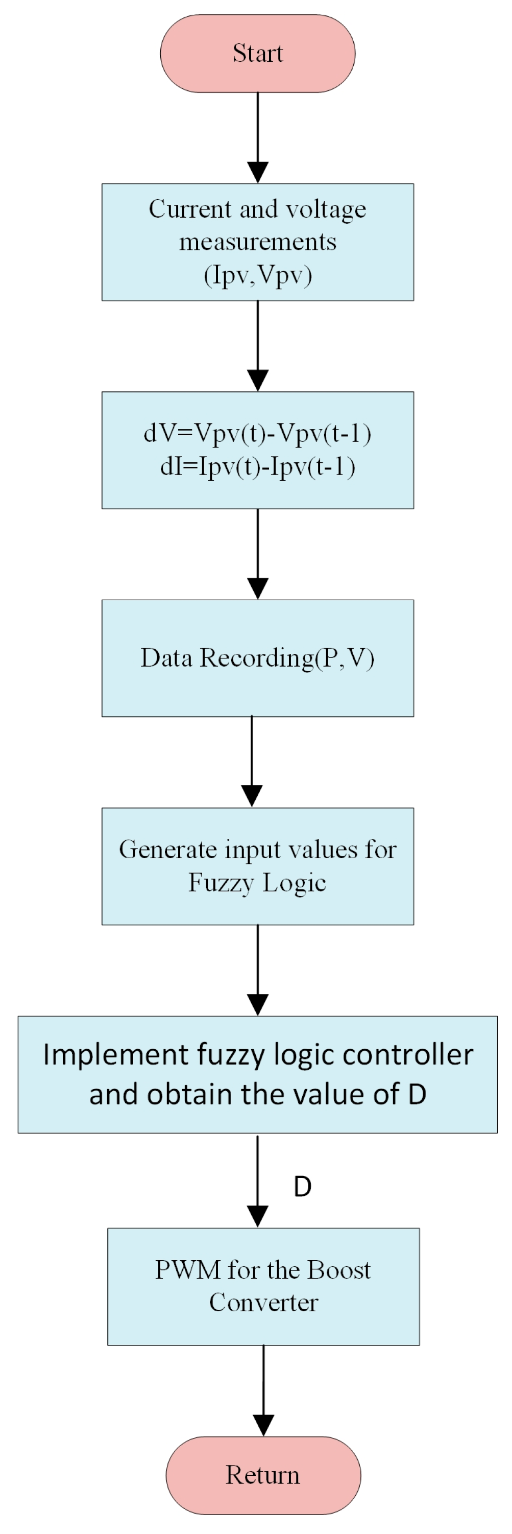
To define the response of the system, a rule set and rule table are produced from the system behavior information obtained for the corresponding FLC input and output values. In general, the knowledge obtained by expert system designers is applied in if-then forms [44]. The sequence of operations, or algorithm, is illustrated in the flowchart presented in Figure 6.
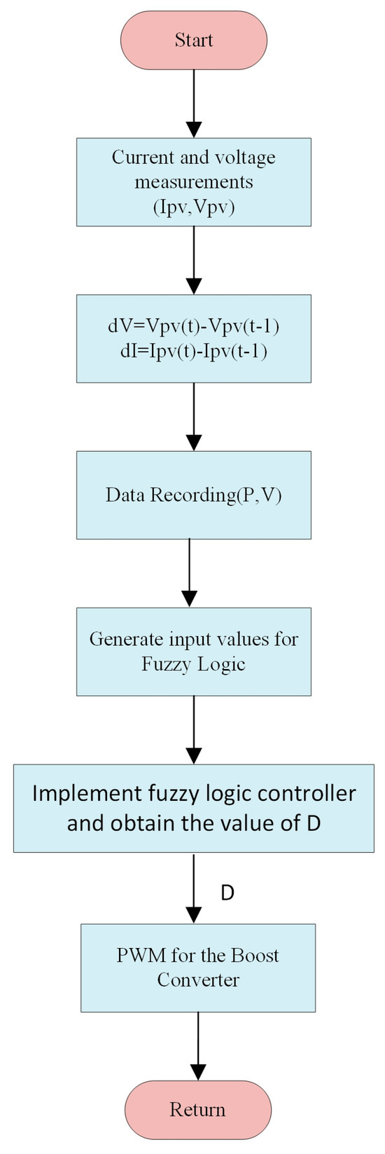
Figure 6.
Fuzzy logic algorithm flow chart.
In a PV system, the input parameters of the FLC are formed depending on Equations (6) and (7).
Subsequently, the error occurring in the system and the alteration in the error value are calculated and employed as genuine input values for fuzzy logic, as illustrated in Equations (8) and (9).
Here, the meanings of the variables are as follows:
- Vk: Present measured panel voltage;Vk−1: Previous value of the present measured panel voltage;Pk: Present calculated panel power;Pk−1: Previous value of the present calculated panel power;e(k): Error value;Δe(k): Change in error value.
In this context, Vk represents the current measured output voltage of the PV panel, while Vk−1 denotes the observed penultimate sampling output voltage. The power variables Pk and Pk−1 are obtained by the formula P = V × I, where P is the power, V is the voltage and I is the current. This is derived from the present and penultimate sampling of the measured voltages and current signals, respectively. The resulting input signals (ΔV and ΔP) and the output variable ΔD (duty cycle change of the converter) are categorized into five categories, as outlined in Table 1.
4.4. Defuzzification Process
As the output variable of the fuzzy controller is a numerical variable, a defuzzification method is required. This is the part where the non-numeric linguistic values obtained from the membership functions determined here are converted back into numerical values as the output of the FLC. For defuzzification, the central weighting method is applied to convert the duty cycle variation (∆D) to an appropriate value [45]. The fuzzified output value of the FLC must be added to a duty cycle reference value, which is currently set to 0.5. This results in the optimal D value, which should be sent to the boost converter as a control signal [46].
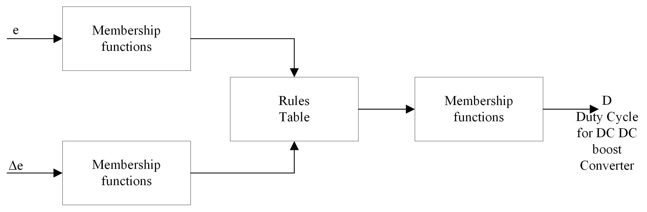
The values obtained from this conversion are used to populate a lookup table containing the requisite control rules. This table is then employed to calculate the output of the controller depicted in Figure 7 in the form of alternative verbal variables. These variables are subsequently combined into a numerical value through the application of the corresponding membership functions (the defuzzification phase), thereby producing the duty cycle of the control signal that drives the power converter, enabling the monitoring of the MPP.

Figure 7.
FLC is based on the proposed method [44,45].
5. Proposed Fuzzy Logic-Controlled MPPT Application
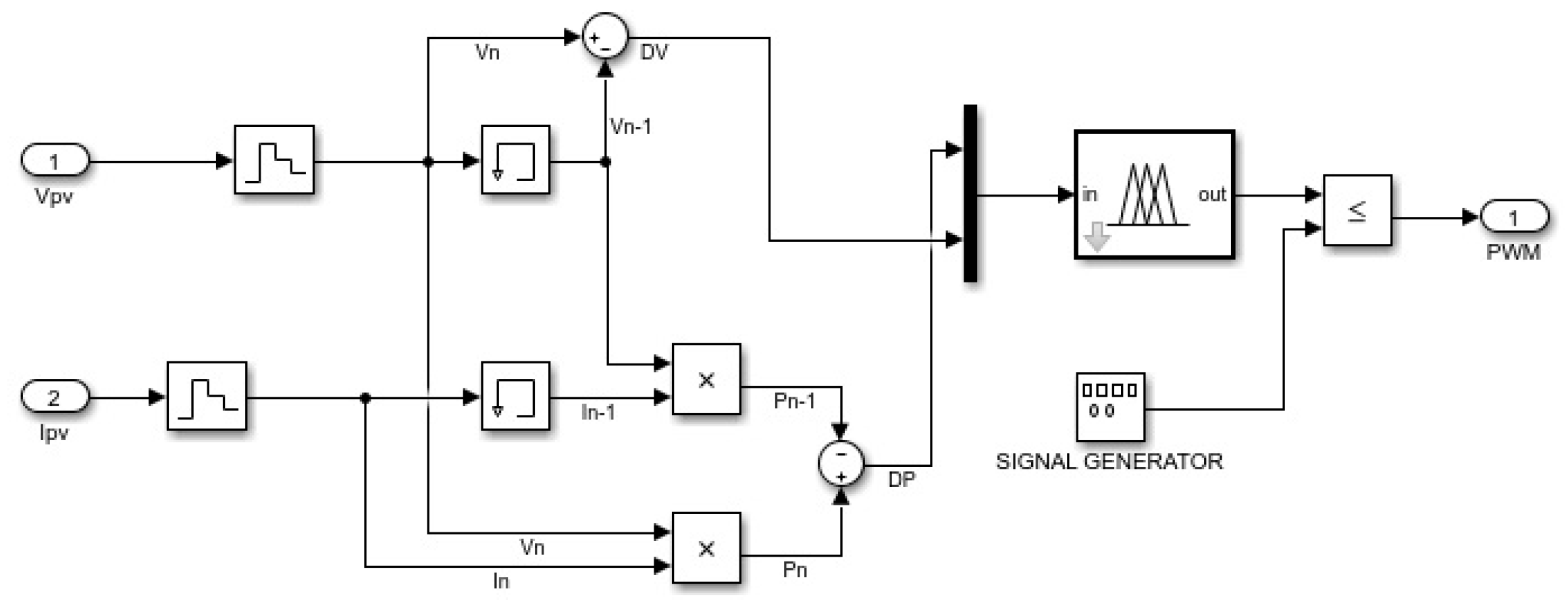
’POMPPT’ used fuzzy logic file properties, and through the Mamdani method, a two-input, single-output system was established. The central weight method was used for defuzzification. The application’s block diagram is displayed in Figure 8. Figure 9 displays the fuzzy logic designer made in the MATLAB program. Here, the input and output parameters of the study are adjusted and shown. DP (change in power of PV panel) and DV (change in voltage of PV panel) are used as input parameters. These two inputs are given in Equations (6) and (7). The reason for using these two inputs is to adapt the PO-based MPPT technique, which is one of the basic MPPT techniques, to the fuzzy logic environment. Alias, it can be referred to as based upon FLC. DD parameter is used as output. The signal generated here is used to produce the switching pulse for the DC-DC converter.
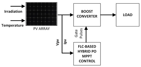
Figure 8.
Block diagram of the implementation.
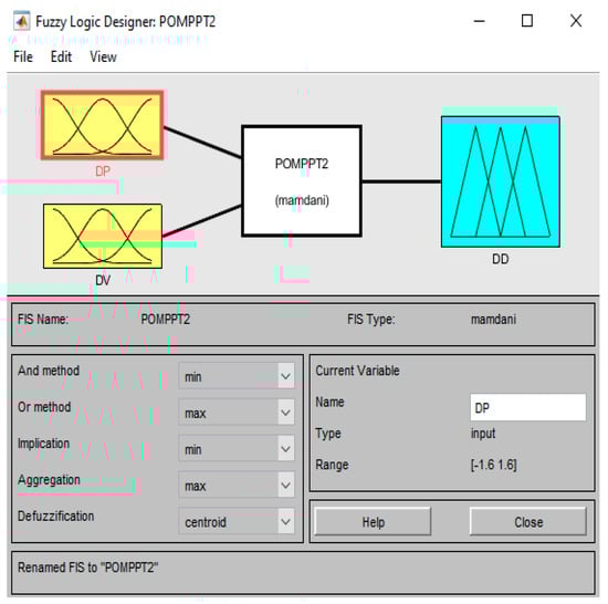
Figure 9.
MATLAB editor view of a fuzzy logic simulation of the implementation.
During fuzzification, the numeric input variables are converted into non-numeric linguistic variables based on membership functions. Figure 10a–c illustrate the membership of DP, DV, and DD, respectively. Five levels of fuzzy are employed for all input and output variables: PS (positive small), NS (negative small), S (zero), PB (positive big), and NB (negative big). A total of 5 × 5 = 25 rules were created for the rule table. The rule table is given in Table 2.
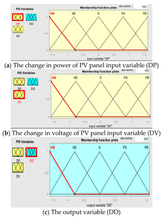
Figure 10.
Input and output membership functions used for FLC.
Table 2.
Rule table of the application.
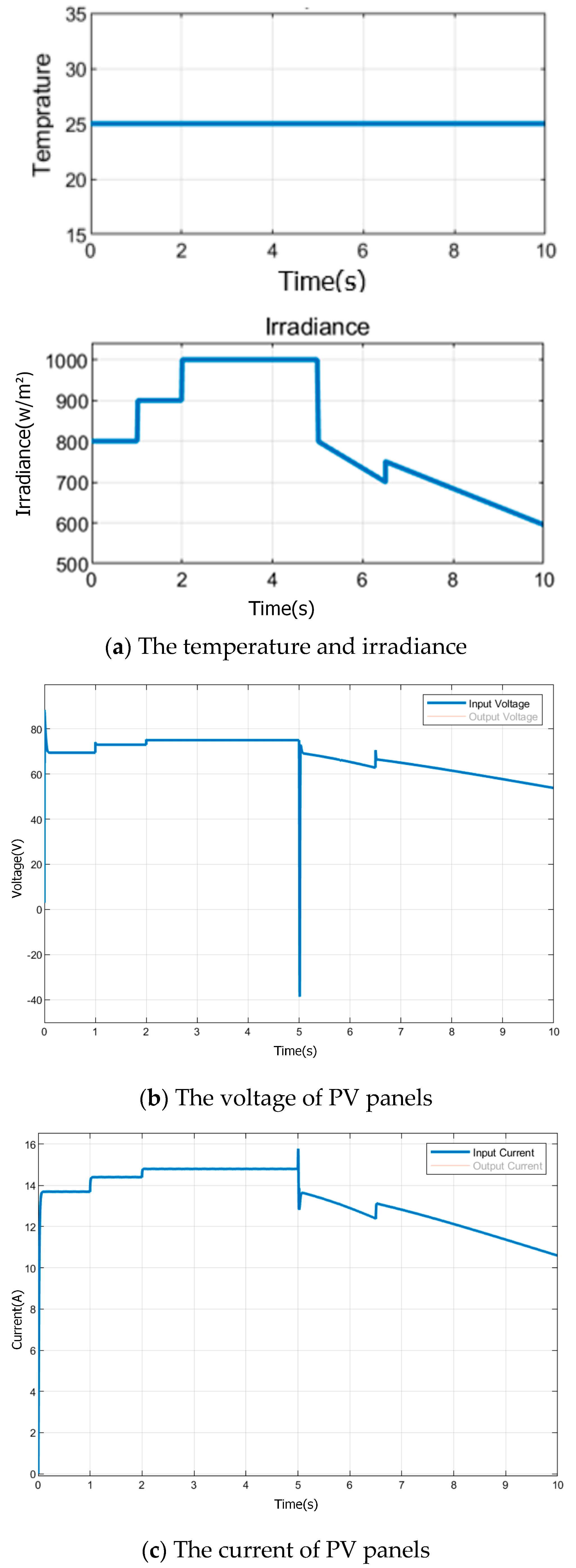
In the application, four SHARP ND-F4Q295 panels, two in series and two in parallel, were used. Figure 11a shows the temperature and radiation graphs applied to the PV system, and Figure 11b shows the voltage and current generated in the PV system. The technical specifications for the SHARP NDQ295 PV panel at standard test conditions (STC) are provided in Table 3.
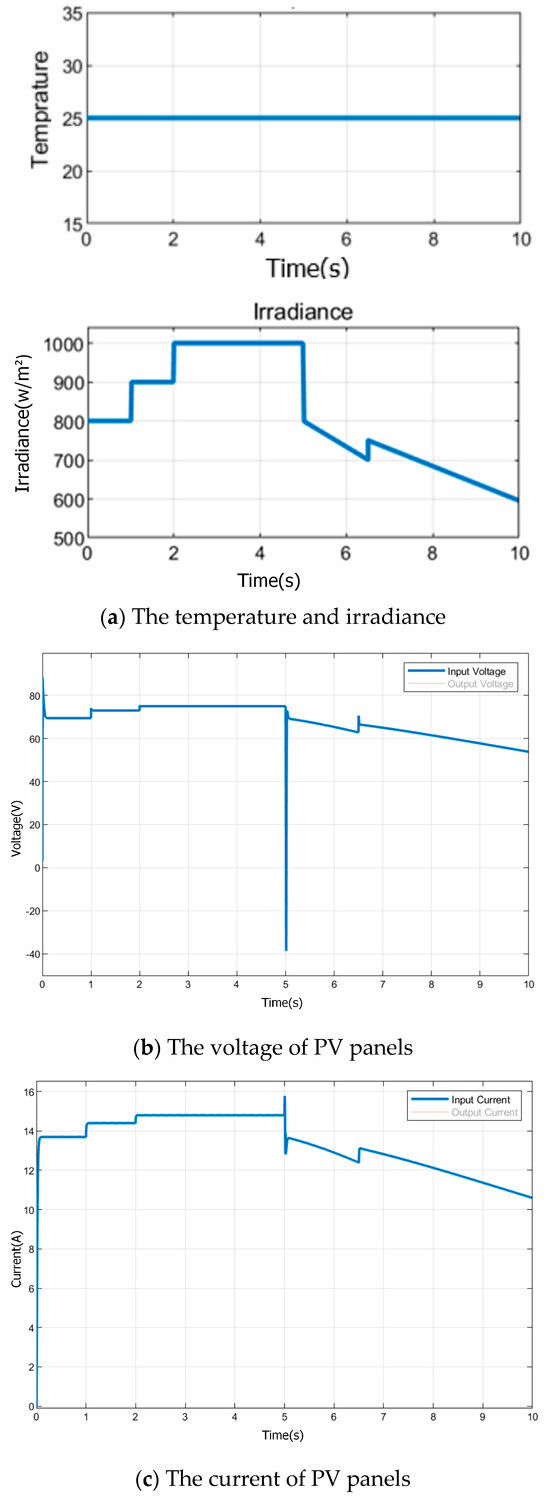
Figure 11.
Voltage, current, temperature, and irradiation graphs of the PV system.
Table 3.
Datasheet of Sharp ND-F4Q295 PV Module.
In this study, the MPPT method is tested using PO- based FLC. The tests were performed with four SHARP solar panels and adaptation was achieved with fuzzy logic using DP and DV parameters. However, the shortcomings such as high computational complexity, sensitivity to noise, slow response time, and oscillations were also highlighted in previous studies. Although FLC provides fast adaptation and stability to environmental changes, it may be affected by small measurement errors due to derivative calculations. Therefore, more optimized and faster-responding algorithms may be required.
6. Simulation Results and Discussion
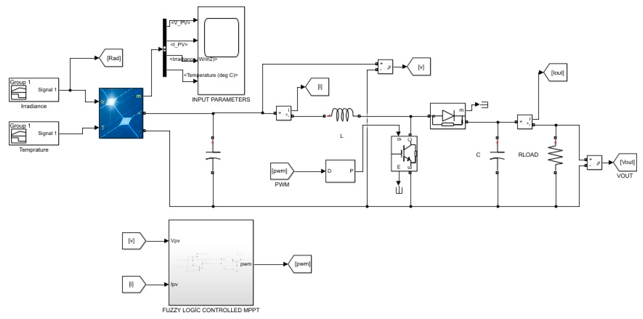
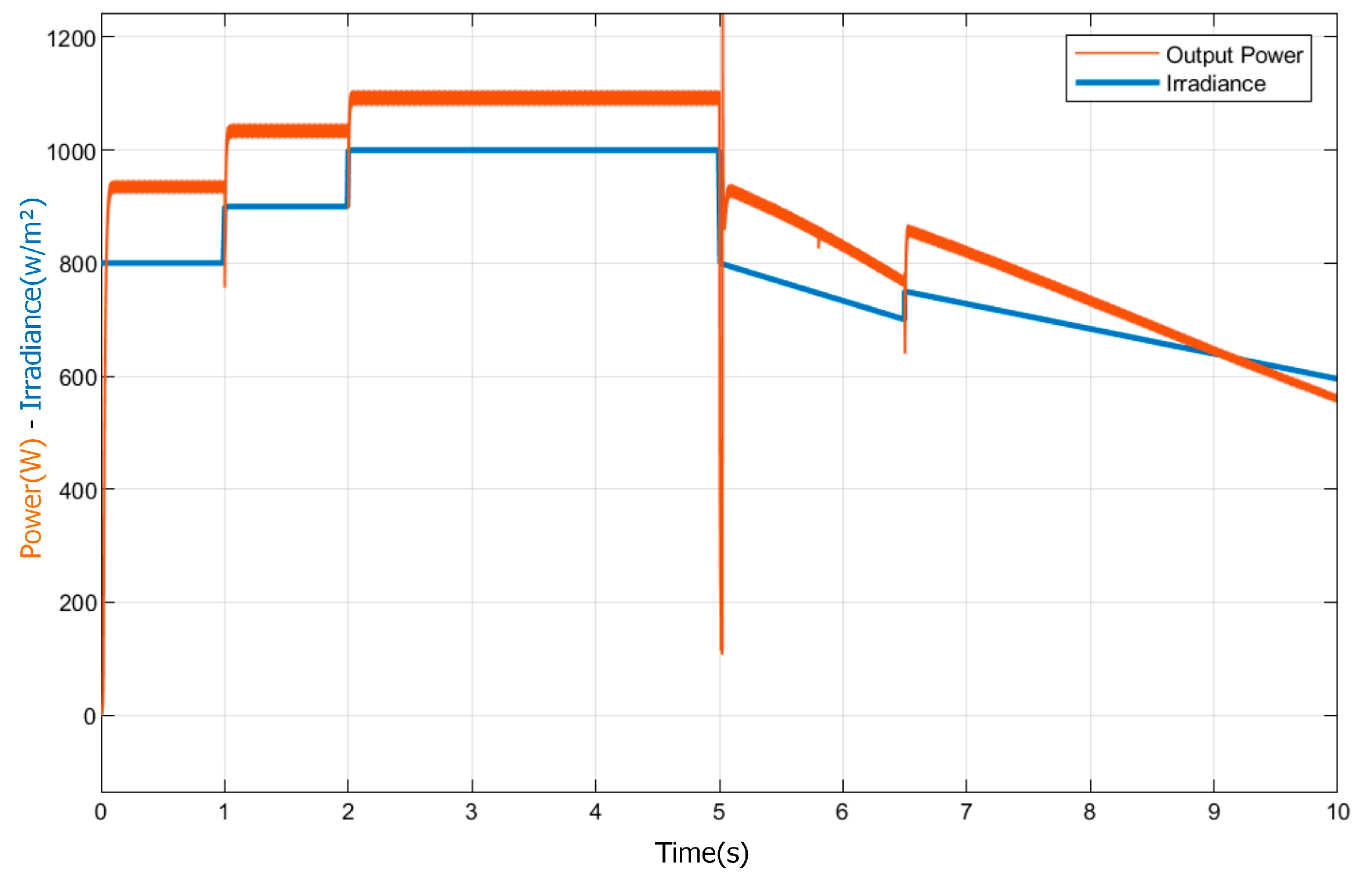
In the simulation studies, two MPPT controllers were compared. The parameters of the boost converter circuit used for both controllers are presented in Table 4. The PV system consists of four SHARP NDQ295 panels, two in series and two in parallel. The parameters of the PV panels are presented in Table 3. As illustrated in Figure 11a, the radiation and temperature values of the PV panels are 800 w/m2 in the interval of 0–1 s, 900 w/m2 in the interval of 1–2 s, 1000 w/m2 in the interval of 2–5 s, max value of 800 w/m2 and min value of 700 w/m2 in the interval of 5–6.5 s, and then sloping irradiation with a max value of 750 w/m2 and min value of 595 w/m2 in the range of 6.5–10 s, according to the suddenly changing weather conditions. In this study, the temperature was applied as constant. The voltage generated by the PV system (800–900–1000 w/m2) is measured as 69.5 V, 72.96 V, and 74.96 V, respectively. The current generated by the photovoltaic (PV) system was measured at 13.696 A, 14.4 A, and 14.8 A, respectively. In Figure 12, the PV system boost circuit and the MATLAB/Simulink circuit are shown. Similarly, in Figure 13, the simulation of the proposed FLC MPPT method in MATLAB/Simulink is seen.
Table 4.
Boost parameters.
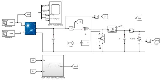
Figure 12.
MATLAB/Simulink simulation study of PV system with fuzzy logic-controlled MPPT.
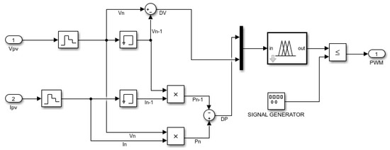
Figure 13.
MATLAB/Simulink simulation study of FLC.
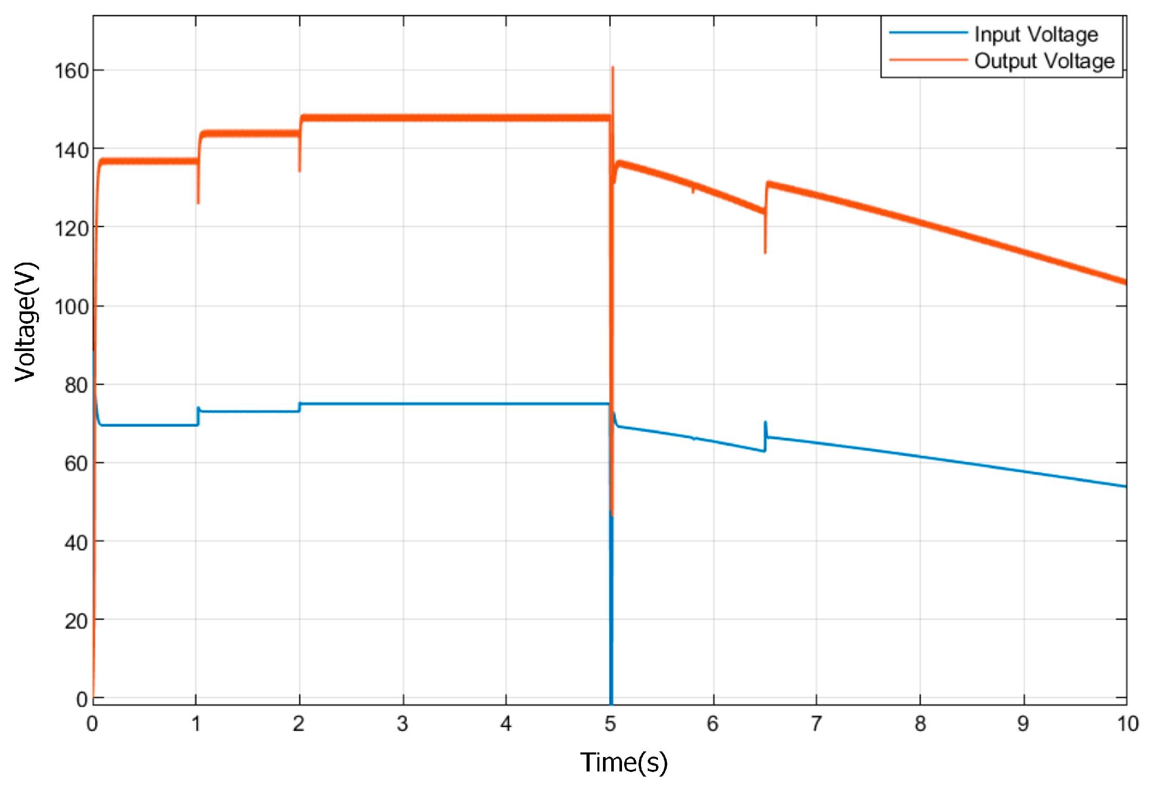
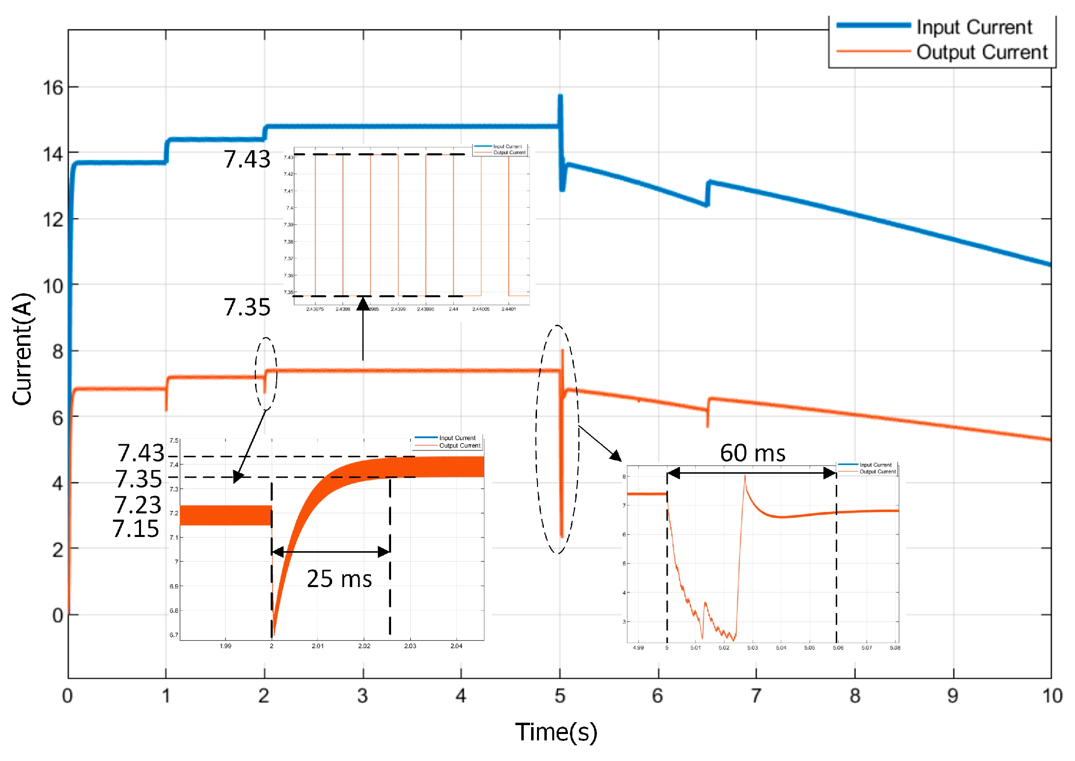
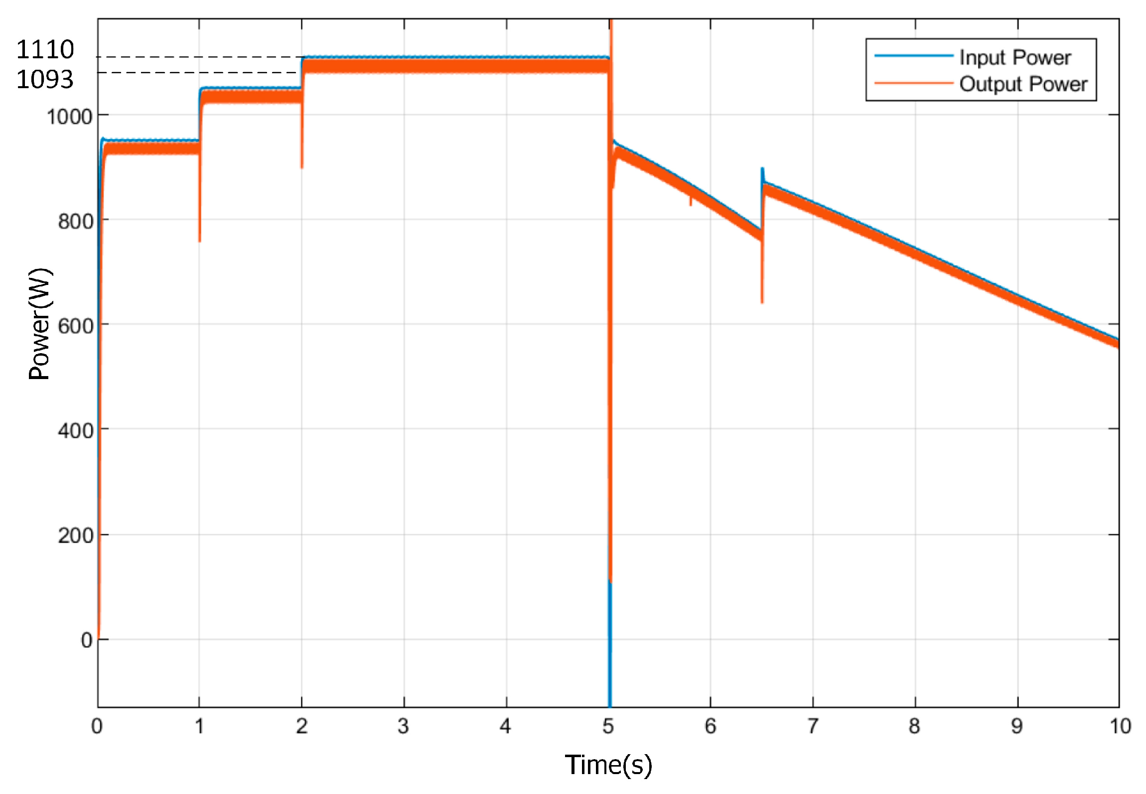
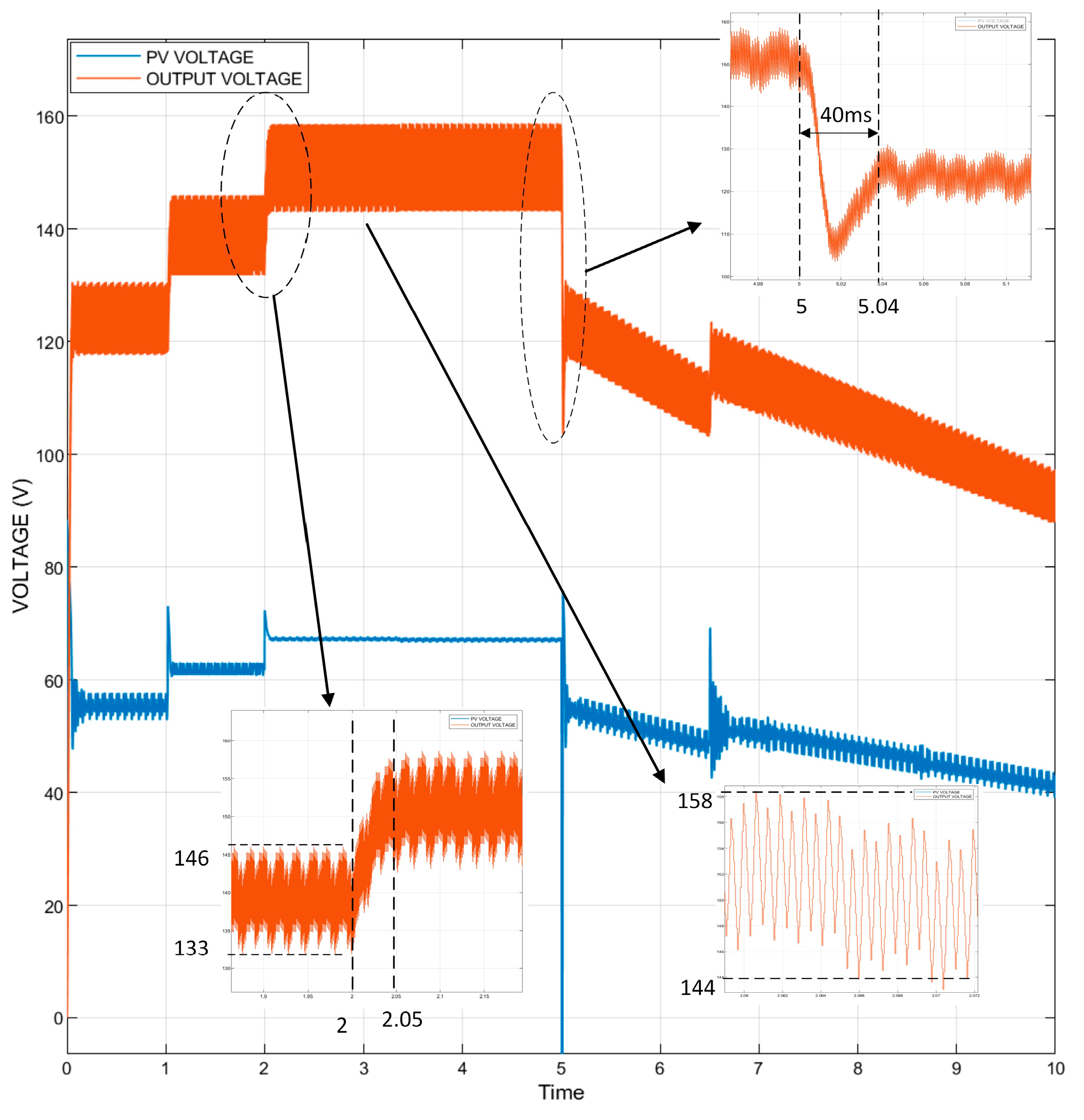
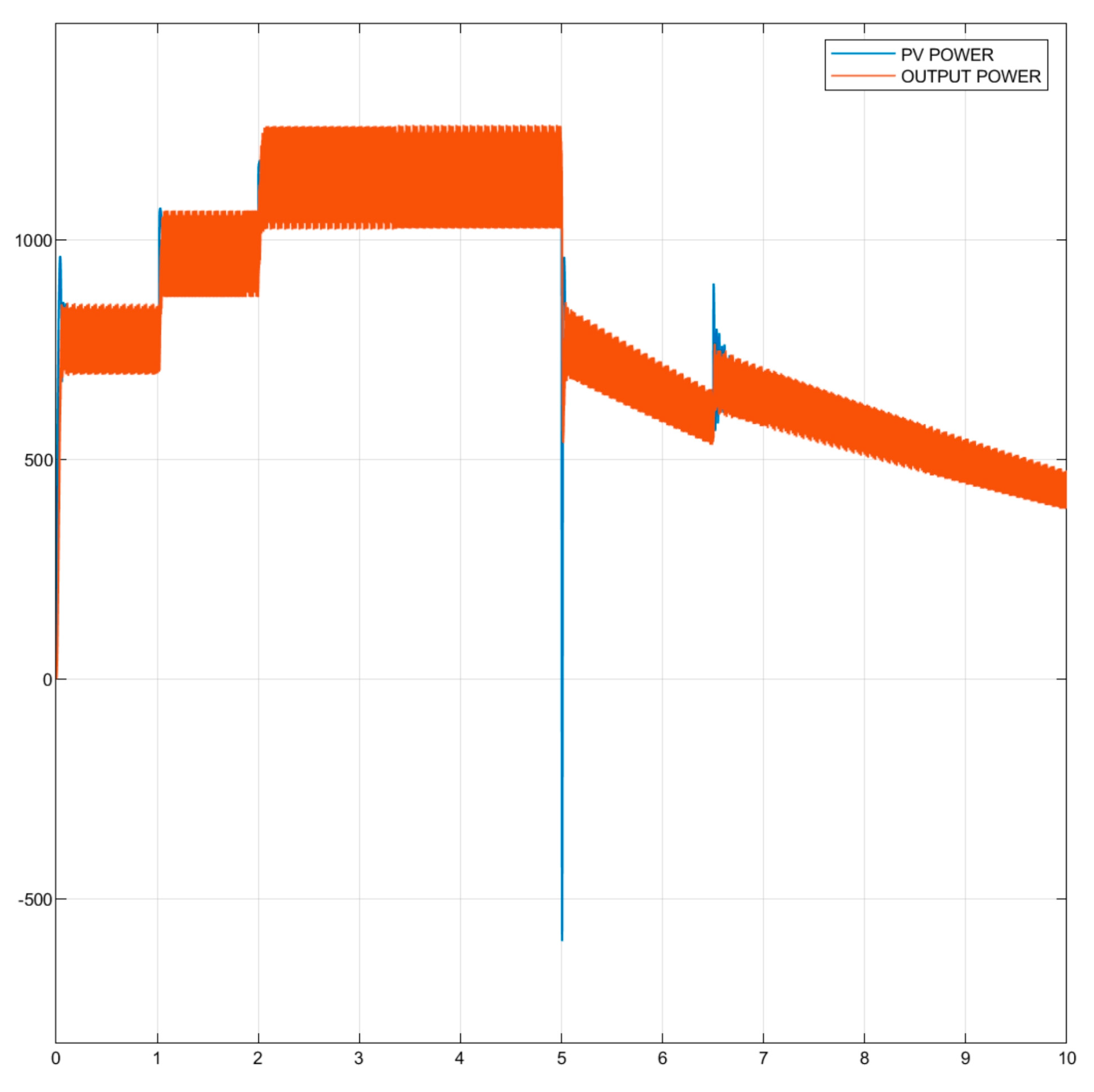
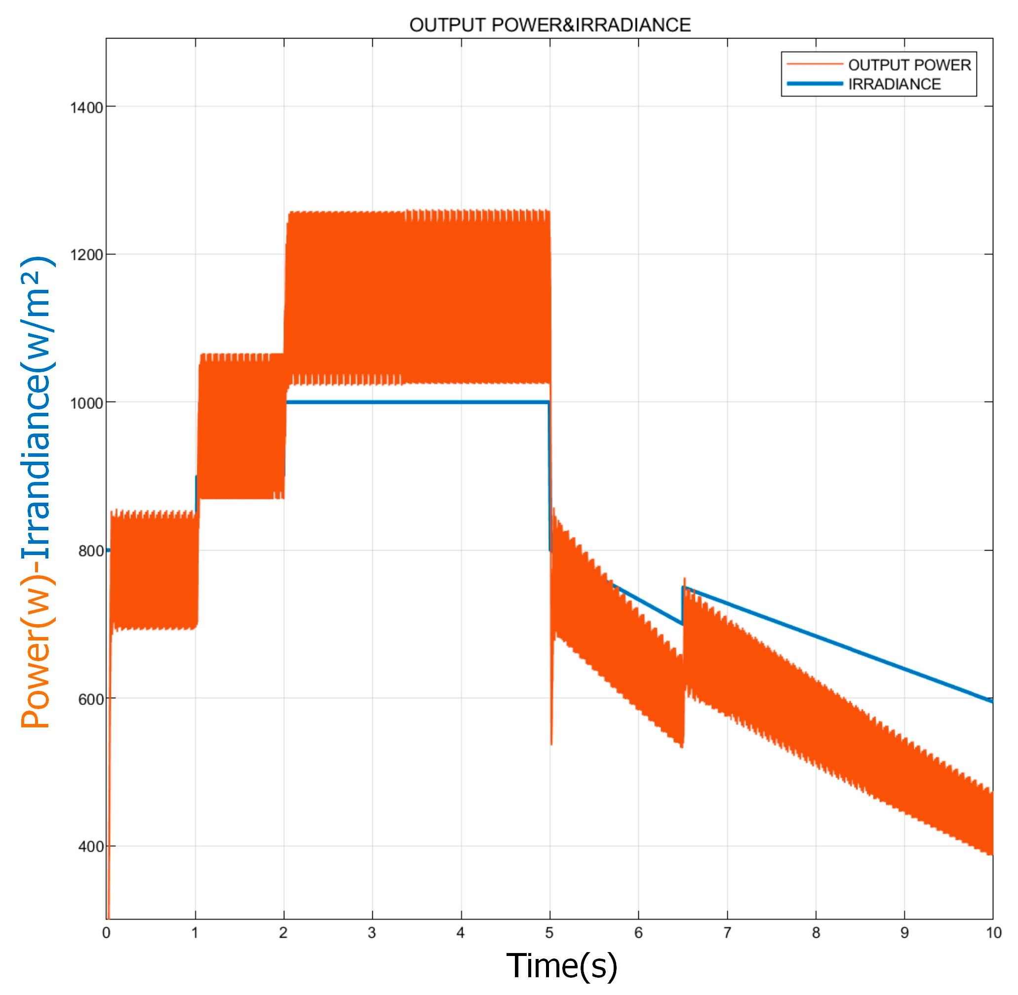
As shown Figure 14 and Figure 15, the FLC-controlled boost circuit increases the voltage to 147.8 V between 2 to 5 sec, and the ripple value of the voltage is measured as 1.6 V. The ripple value of the voltage ΔV=1.08% was calculated. In addition, in instantaneous variations in radiation, the FLC controller stabilizes the voltage as rapidly as 25 ms (Figure 15). In Figure 16, when the currents of the FLC-controlled boost converter are examined, it is seen that the ripple is 0.08 A. However, at the current, a large ripple occurs in the sudden decrease in radiation (at 6.5 s). In Figure 17, the power generated by the FLC controller follows the power generated by the PV system rapidly and efficiently. It was observed that the oscillations in the power generated with the FLC controller were very low. Figure 18 illustrates that the FLC controller is capable of effectively tracking the output power in the event of sudden changes in radiation. Table 5 presents the power generated in the photovoltaic (PV) system and the output power of the boost converter, both of which are functions of the radiation values.
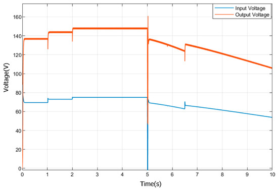
Figure 14.
The voltage of the PV system and FLC-controlled boost converter output voltage.
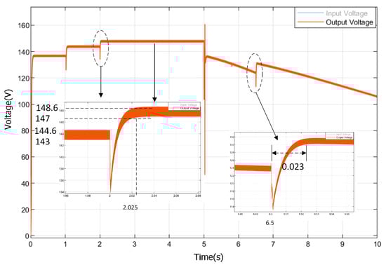
Figure 15.
The FLC-controlled boost converter output voltage.

Figure 16.
The current of the PV system and the FLC-controlled boost converter output current.
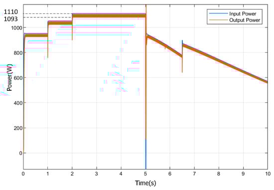
Figure 17.
Power generated from the PV module and fuzzy logic-controlled boost output power.
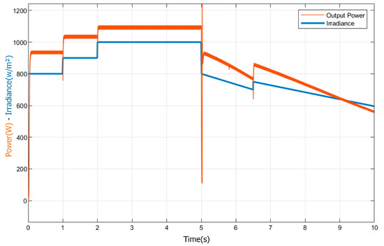
Figure 18.
Incoming PV panel irradiation and FLC-controlled boost output power.
Table 5.
Radiation, PV power, and output power table of FLC-controlled system.
Figure 19 illustrates the voltage of the photovoltaic (PV) system and the boost converter output voltage in response to an increase in conductivity, as determined by the algorithm. The mean value of the boost output voltage within the 2–5 s interval is 151 volts. The ripple in the voltage (ΔV) is measured as 13 V. ΔV is calculated as 8.6% (ΔV = 8.6%). The voltage becomes stable in 40 ms according to varying weather conditions. An examination of the output current of the boost converter, as illustrated in Figure 20, the average value between 2 to 5 sec is measured as 7.55 A, and the ripple in the current (ΔI) is 0.7 A. ΔI was calculated as 9.27%. As the irradiance declines from 1000 w/m2 to 800 w/m2 at 5th sec, the ripple in the current decreases to 5.5 A. The current becomes stable within 40 ms. It can be seen that the IncCon-controlled boost output power tracks the PV input power in Figure 21 and Figure 22. Table 6 shows each irradiance value, which displays the power generated by the PV system and the output power of the boost converter.
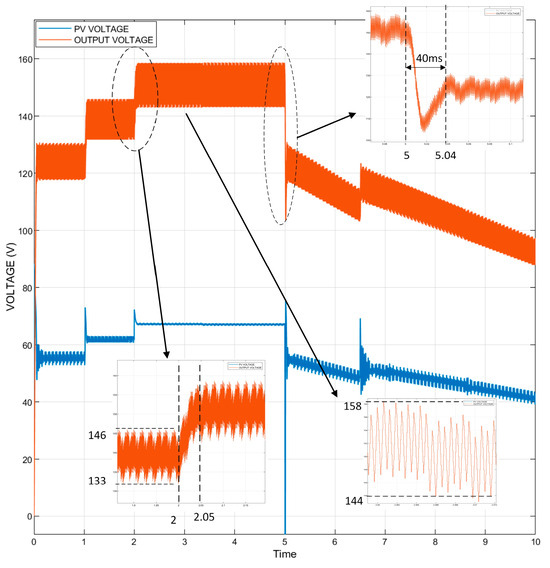
Figure 19.
PV system voltage and IncCon-controlled boost output voltage.
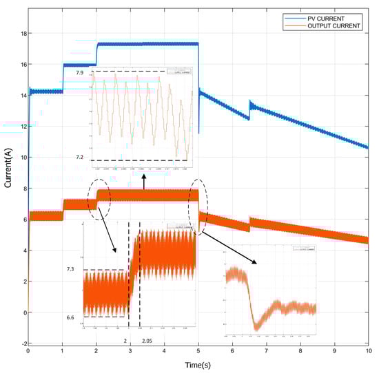
Figure 20.
PV system current and IncCon-controlled boost output current.
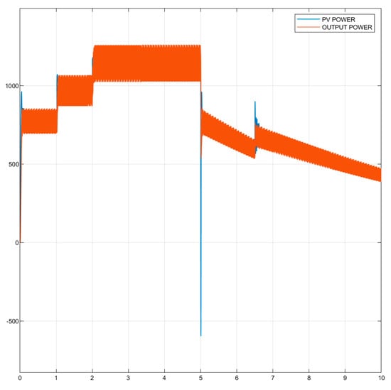
Figure 21.
PV system-generated power and IncCon-controlled boost converter output power.

Figure 22.
Incoming PV panel irradiation and the IncCon-controlled boost output power.
Table 6.
Radiation, PV power, and output power table of the IncCon-controlled system.
Table 7 presents the performance benchmarking of the proposed method and a comparison with MPPT strategies currently available in the literature. The characteristics used to compare the proposed method with the methods used in the literature include efficiency and power. The results in Table 7 show that the proposed method is easier to use and more successful than the methods in the literature.
Table 7.
A comparative analysis of the key features: the proposed control method in relation to existing methods.
7. Conclusions
Technological development and increasing energy demand have increased interest in solar energy, which is classified as renewable, environmentally friendly, and green energy. This study aimed to compare the widely used IncCon MPPT method and the FLC MPPT method, which is an intelligent hybrid method, through analysis in a MATLAB/Simulink environment. This paper presents evidence that the hybrid and intelligent maximum power point tracking (MPPT) method produces fewer oscillations than the classical IncCon method. While the voltage ripple is 1% in the proposed method, it is 8.6% in the IncCon method. This situation shows that the proposed method effectively reduces the voltage ripple. Likewise, while the current ripple in the proposed method is 1.08%, the current ripple in the second method is 9.27%. The proposed FLC method stabilizes the voltage faster and more efficiently (25 ms) in sudden changes in weather conditions. It is demonstrated that the IncCon method produces more output power than the proposed FLC algorithm. It has been demonstrated that the proposed hybrid FLC method generates fewer ripples and stabilizes current and voltage faster than the IncCon algorithm. For future work, in terms of efficiency and stability, continuous experimentation and verification under various operating scenarios with low-cost microcontrollers is recommended to fully reveal the effective results of the proposed fuzzy logic-based MPPT control approach.
Author Contributions
Conceptualization, F.Ç.; methodology, F.Ç.; software, F.Ç.; formal analysis, M.R.T.; investigation, F.Ç., Z.A., and M.R.T.; resources, M.R.T.; data curation, F.Ç.; writing—original draft preparation, F.Ç.; writing—review and editing, F.Ç. and M.R.T.; visualization, F.Ç.; supervision, Z.A. and M.R.T.; All authors have read and agreed to the published version of the manuscript.
Funding
This research received no external funding.
Data Availability Statement
The original contributions presented in the study are included in the article, further inquiries can be directed to the corresponding author.
Conflicts of Interest
The authors declare no conflicts of interest.
References
- Shivakumara, A.; Dobbinsb, A.; Fahlb, U.; Singhc, A. Drivers of renewable energy deployment in the EU: An analysis of past trends and projections. Energy Strategy Rev. 2019, 26, 100402. [Google Scholar] [CrossRef]
- Santos, J.L.; Antunes, F.; Chehab, A. A maximum power point tracker for PV systems using a high-performance boost converter. Sol. Energy 2005, 80, 772–778. [Google Scholar] [CrossRef]
- Yu, T.C.; Chien, T.S. Analysis and simulation of characteristics and maximum power point tracking for photovoltaic systems. In Proceedings of the Power Electronics and Drive Systems Conference, Taipei, Taiwan, 2–5 November 2009; pp. 1339–1344. [Google Scholar] [CrossRef]
- Schmalensee, R. The future of solar energy: A personal assessment. Energy Econ. 2015, 52, 142–148. [Google Scholar] [CrossRef]
- Bharti, M.; Kumar, U. Virtualization and sımulatıon of incremental conductance mppt based two-phase interleaved boost converter usıng sımulınk in Matlab. Int. J. Technol. Res. Eng. 2017, 4, 1686–1691. [Google Scholar]
- Esram, T.; Chapman, P.L. Comparison of photovoltaic array maximum power point tracking techniques. IEEE Trans. Energy Convers. 2007, 22, 439–449. [Google Scholar] [CrossRef]
- Cakmak, F.; Aydogmuş, Z.; Tür, M.R. Mppt control for pv systems with analytical analysis fractional open circuit voltage method. In Proceedings of the 2022 Global Energy Conference (GEC), Batman, Turkey, 26–29 October 2022. [Google Scholar] [CrossRef]
- Algarin, C.R.; Cabarcas, J.C.; Llanos, A.P. Low-cost fuzzy logic control for greenhouse environments with web monitoring. Electronics 2017, 6, 71. [Google Scholar] [CrossRef]
- Noman, A.M.; Addoweesh, K.E.; Mashaly, H.M. Fuzzy logic control method for mppt of PV systems. In Proceedings of the 38th Annual Conference on IEEE Industrial Electronics Society (IECON), Montreal, QC, Canada, 25–28 October 2012. [Google Scholar] [CrossRef]
- Hassan, H.H.; Geliel, M.A.; Abu-Zeid, M. A proposed fuzzy controller for mppt of a photovoltaic system. In Proceedings of the 2014 IEEE Conference on Energy Conversion (CENCON), Johor Bahru, Malaysia, 13–14 October 2014. [Google Scholar] [CrossRef]
- Zainuri, M.A.A.M.; Radzi, M.A.M.; Soh, A.C.; Rahim, N.A. Adaptive p&o-fuzzy control mppt for pv boost dc-dc converter. In Proceedings of the IEEE International Conference on Power and Energy (PECon), Kota Kinabalu, Malezya, 2–5 December 2012. [Google Scholar] [CrossRef]
- Algarín, C.R.; Giraldo, J.T.; Álvarez, O.R. Fuzzy logic-based mppt controller for a PV system. Energies 2017, 10, 2036. [Google Scholar] [CrossRef]
- Kumar, R.; Kumar, B.; Swaroop, D. Fuzzy logic-based improved PO mppt technique for partial shading conditions. In Proceedings of the International Conference on Computing, Power and Communication Technologies (GUCON), Greater Noida, India, 28–29 September 2018. [Google Scholar] [CrossRef]
- Wilamowski, B.M.; Li, X. Fuzzy system based maximum power point tracking for PV system. In Proceedings of the 28th Annual Conference in IEEE Industrial Electronics Society, Seville, Spain, 5–8 November 2002. [Google Scholar] [CrossRef]
- Hayder, W.W.; Abid, A.; Sbita, L. Intelligent mppt algorithm for PV system based on fuzzy logic. In Proceedings of the 17th International Multi-Conference on Systems, Signals & Devices (SSD), Monastir, Tunisia, 20–23 July 2020. [Google Scholar] [CrossRef]
- Khan, A.A.; Aqil, M.; Malik, N.; Ullah, F.; Khalid, A. Comparative analysis of mppt techniques for sepic based pv system. Int. J. Eng. Work. 2021, 8, 1–7. [Google Scholar] [CrossRef]
- Nivedha, S.; Vijayalaxmi, M. Performance analysis of fuzzy based hybrid mppt algorithm for photovoltaic system. In Proceedings of the International Conference on Communication, Control and Information Sciences (ICCISc), Idukki, India, 16–18 June 2021. [Google Scholar] [CrossRef]
- Özbay, H. Comparison of sliding mode and fuzzy logic mppt techniques for PV systems. Electron. Lett. Sci. Eng. 2020, 16, 26–35. [Google Scholar]
- Yilmaza, Ü.; Kircaya, A.; Börekçi, S. PV system fuzzy logic mppt method and pi control as a charge controller. Renew. Sustain. Energy Rev. 2018, 81, 994–1001. [Google Scholar] [CrossRef]
- Abdellatif, W.S.E.; Mohamed, M.S.; Barakat, S.; Brisha, A. A Fuzzy Logic Controller Based MPPT Technique for Photovoltaic Generation System. Int. J. Electr. Eng. Inform. 2021, 13, 394–417. [Google Scholar] [CrossRef]
- Ullah, K.; Ishaq, M.; Tchier, F.; Ahmad, H.; Ahmad, Z. Fuzzy-based maximum power point tracking (MPPT) control system for photovoltaic power generation system. Results Eng. 2023, 20, 101466. [Google Scholar] [CrossRef]
- Abdullah, M.Z.; Sudiharto, I.; Eviningsih, R.P. Photovoltaic System MPPT using Fuzzy Logic Controller. In Proceedings of the 2020 International Seminar on Application for Technology of Information and Communication, Semarang, Indonesia, 19–20 September 2020. [Google Scholar] [CrossRef]
- Fayaz, F.; Siddiqui, I. Maximum power point tracking algorithms for photovoltaic applications. Int. J. Res. Appl. Sci. Eng. Technol. (IJRASET) 2019, 7, 141–152. [Google Scholar] [CrossRef]
- Saravanan, S.; Babu, N.R. Maximum Power Point Tracking Algorithms for Photovoltaic System—A Review. Renew. Sustain. Energy Rev. 2016, 57, 192–204. [Google Scholar] [CrossRef]
- Farayola, A.M.; Hasan, A.N.; Ali, A. Efficient photovoltaic MPPT system using coarse Gaussian support vector machine and artificial neural network techniques. Int. J. Innov. Comput. Inf. Control 2018, 14, 323–339. [Google Scholar]
- Assahout, S.; Elaissaoui, H.; El Ougli, A.; Tidhaf, B.; Zrouri, H. A neural network and fuzzy logic based MPPT algorithm for photovoltaic pumping system. Int. J. Power Electron. Drive Syst. (IJPEDS) 2018, 9, 1823–1833. [Google Scholar] [CrossRef]
- Messai, A.; Mellit, A.; Pavan, A.M.; Guessoum, A.; Mekki, H. FPGA-based implementation of a fuzzy controller (MPPT) for the photovoltaic module. Energy Convers. Manag. 2011, 52, 2695–2704. [Google Scholar] [CrossRef]
- Kottas, T.L.; Boutalis, Y.S.; Karlis, A.D. New maximum power point tracker for PV arrays using the fuzzy controller in close cooperation with fuzzy cognitive networks. IEEE Trans. Energy Convers. 2006, 21, 793–803. [Google Scholar] [CrossRef]
- Algazar, M.M.; AL-monier, H.; EL-halim, H.A.; Salem, M.E.E.K. Maximum power point tracking using fuzzy logic control. Electr. Power Energy Syst. 2012, 39, 21–28. [Google Scholar] [CrossRef]
- Koutroulis, E.; Blaabjerg, F. A new technique for tracking the global maximum power point of PV arrays operating under partial shading conditions. IEEE J. Photovolt. 2012, 2, 184–190. [Google Scholar] [CrossRef]
- Cavalcanti, M.C.; Oliveira, K.C.; Azevedo, G.M.; Moreira, D.; Neves, F.A. Maximum power point tracking techniques for photovoltaic systems. Prz. Elektrotechniczny 2006, 82, 49–56. [Google Scholar] [CrossRef]
- Ishaque, K.; Salam, Z. A review of maximum power point tracking techniques of PV system for uniform insolation and partial shading condition. Renew. Sustain. Energy Rev. 2013, 19, 475–488. [Google Scholar] [CrossRef]
- Ahmed, N.A.; Miyatake, M. A novel maximum power point tracking for photovoltaic applications under partially shaded insolation conditions. Electr. Power Syst. Res. 2008, 78, 777–784. [Google Scholar] [CrossRef]
- Femia, N.; Granozio, D.; Petrone, G.; Spagnuolo, G.; Vitelli, M. Predictive adaptive mppt perturb and observe method. IEEE Trans. Aerosp. Electron. Syst. 2007, 43, 934–950. [Google Scholar] [CrossRef]
- Femia, N.; Petrone, G.; Spagnuolo, G.; Vitelli, M. Optimization of perturb and observe maximum power point tracking method. IEEE Trans. Power Electron. 2005, 20, 963–973. [Google Scholar] [CrossRef]
- Tavası, C.T.; Chen, J.Y.; Chu, C.P.; Huang, Y.S. A fast maximum power point tracker for photovoltaic power systems. In Proceedings of the IECON ’99 Pro. 25th Annual Conference of the IEEE Industrial Electronics Society, San Jose, CA, USA, 29 November–3 December 1999. [Google Scholar] [CrossRef]
- Veerachary, M.; Senjyu, T.; Uezato, K. Neural-network-based maximum-power-point tracking of coupled-inductor interleaved-boost converter-supplied PV system using fuzzy controller. IEEE Trans. Ind. Electron. 2003, 50, 749–758. [Google Scholar] [CrossRef]
- Guenounou, O.; Dahhou, B.; Chabourd, F. Adaptive fuzzy controller based MPPT for photovoltaic systems. Energy Convers. Manag. 2014, 78, 843–850. [Google Scholar] [CrossRef]
- Syafaruddin; Karatepe, E.; Hiyama, T. Artificial neural network coordinated fuzzy controller based maximum power point tracking control under partially shaded conditions. IET Renew. Power Gener. 2009, 3, 239–253. [Google Scholar] [CrossRef]
- Sousa, G.C.D.; Bose, B.K. A fuzzy set theory-based control of a phase-controlled converter DC machine drive. IEEE Trans. Ind. Appl. 1994, 30, 34–44. [Google Scholar] [CrossRef]
- Available online: https://ahmetatasoglu98.medium.com/ (accessed on 28 July 2022).
- Ödük, M.N. Bulanık Mantık Yöntemi ve Uygulamaları. Iksad Press: Ankara, Turkey, 2019; pp. 13–19. [Google Scholar]
- Nabulsi, A.A.; Dhaouadi, R. Efficiency optimization of a DSP-based stand-alone pv system using fuzzy logic and dual-mppt control. IEEE Trans. Indus. Inform. 2012, 8, 573–584. [Google Scholar] [CrossRef]
- Rahmani, R.; Seyedmahmoudian, M.M.; Mekhilef, S.; Yusof, R. Implementation of fuzzy logic maximum power point tracking controller for photovoltaic system. Am. J. Appl. Sci. 2013, 10, 209–218. [Google Scholar] [CrossRef]
- Adly, M.; Besheer, A.H. An optimized fuzzy maximum power point tracker for stand-alone photovoltaic systems, ant colony approach. In Proceedings of the Seventh IEEE Conference on Industrial Electronics and Applications (ICIEA), Singapore, 18–20 July 2012; pp. 113–119. [Google Scholar] [CrossRef]
- Blaabjerg, F.; Ionel, D.M. Renewable Energy Devices and Systems with Simulations in Matlab and Ansys; CRC Press, Taylor & Francis Group: Boca Raton, FL, USA, 2017. [Google Scholar]


Disclaimer/Publisher’s Note: The statements, opinions and data contained in all publications are solely those of the individual author(s) and contributor(s) and not of MDPI and/or the editor(s). MDPI and/or the editor(s) disclaim responsibility for any injury to people or property resulting from any ideas, methods, instructions or products referred to in the content. |
© 2024 by the authors. Licensee MDPI, Basel, Switzerland. This article is an open access article distributed under the terms and conditions of the Creative Commons Attribution (CC BY) license (https://creativecommons.org/licenses/by/4.0/).