Review

High-Efficiency, Lightweight, and Reliable Integrated Structures—The Future of Fuel Cells and Electrolyzers

by
Jun Zhang
1,
Runjin Deng
1,
Yanyan Wang
1,
Conggan Ma
1,
Zhaojie Shen
1,
Yitao Shen
1,
Stuart M. Holmes
2,* and
Zhaoqi Ji
1,*
1
School of Automotive Engineering, Harbin Institute of Technology, Weihai 264209, China
2
Department of Chemical Engineering, The University of Manchester, Manchester M13 9PL, UK
*
Authors to whom correspondence should be addressed.
Energies 2025, 18(19), 5319; https://doi.org/10.3390/en18195319
Submission received: 30 August 2025 / Revised: 24 September 2025 / Accepted: 26 September 2025 / Published: 9 October 2025
(This article belongs to the Special Issue Next-Generation Fuel Cells: Innovations in Materials and Performance)

Abstract

The high efficiency, light weight, and reliability of hydrogen energy electrochemical equipment are among the future development directions. Membrane electrode assemblies (MEAs) and electrolyzers, as key components, have structures and strengths that determine the efficiency of their power generation and the hydrogen production efficiency of electrolyzers. This article summarizes the evolution of membrane electrode and electrolyzer structures, and their power and efficiency in recent years, highlighting the significant role of integrated structures in promoting proton transport and enhancing performance. Finally, it proposes the development direction of integrating electrolyte and electrode manufacturing using phase-change methods.

1. Introduction

The extensive exploitation and use of fossil energy have led to resource scarcity and severe environmental pollution, exerting an inevitable impact on humans and other living beings [1,2]. Hydrogen energy has emerged as one of the future development directions with its zero-carbon emission and high energy density [3]. Proton exchange membrane fuel cells (PEMFCs), as one of the high-efficiency devices for converting hydrogen energy into electricity, are increasingly penetrating the transportation, power generation, and manufacturing industries. Consequently, there is a corresponding increase in production across the fields of air, land, and sea [4].
Currently, the typical structure of PEMFCs consists of a membrane electrode assembly (MEA) and a pair of bipolar plates (BPs). Each single cell is connected in series to form a fuel cell stack [5]. The fuel gas (H2) and oxidizing gas (air/O2) enter the MEA through the flow channels on the BPs. Within the MEA, both the anode and the cathode are equipped with a gas diffusion layer (carbon paper) made from carbon fibers, facilitating the transport of gases and liquids. This is accompanied by a microporous layer (MPL) that promotes mass transfer by generating different pressures through the gradient of pore size. Subsequently, the H2 and O2 gases reach the chemical reaction site known as the catalyst layer (CL), where they undergo oxidation and reduction processes under the catalytic action of commercial platinum catalysts. The produced protons and electrons traverse the proton exchange membrane (typically a perfluorosulphonate-type polymer membrane) and external circuits, respectively [6]. Consequently, the selection of materials and the fabrication processes are critical for enhancing the performance of PEMFCs [7]. The second-generation Mirai achieves stack power densities of 4.4 kW/L and 5.4 kW/L, with and without end plates, respectively [8]. Japan’s New Energy and Industrial Technology Development Organization (Japan NEDO) has set targets of 6.0 kW/L and 9.0 kW/L for the years 2030 and 2040, respectively. Thus, innovative structures of MEAs could significantly contribute to increasing volumetric power density, as illustrated in Figure 1.

2. Integrated MEAs

Conventional MEA fabrication processes, including catalyst-coated substrates and catalyst-coated membranes, easily result in cracking of the membrane and electrodes. Consequently, the integration of the MEA has garnered significant attention from researchers in fuel cells and electrolytic water in recent years. This has led to advancements such as the integrated electrode, the integrated MEA, and finally, the integrated bipolar plate/MEA (BP–MEA).

2.1. Integrated Electrode

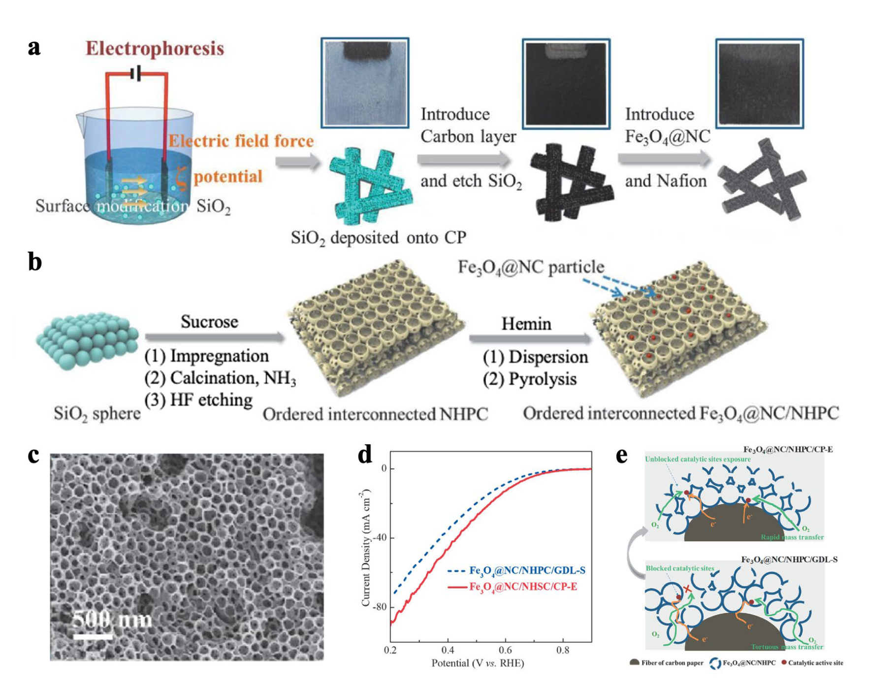
The integrated electrode fabrication process is well-established, encompassing a variety of electrochemical technologies such as electrodeposition [9], electrospinning, electrophoresis [10], and gas-phase deposition (including arc plasma deposition [11]). Delikaya et al. [12] prepared an integrated GDE@GDL through combining electrospun and wet impregnation techniques, which helped to alleviate the limitation of O2 diffusion. Despite the researchers indicating that this novel GDE@GDL could reduce the dosage of Pt, the MEA performance was significantly lower than that of the sprayed GDE. Concurrently, Song’s group [10] utilized an electrophoresis method to synthesize a 3D integrated electrode. SiO2 nanoparticles were directed and deposited onto conventional carbon paper (CP) under an electric field, as depicted in Figure 2a. An in situ growth of Fe3O4@NC/NHPC took place on the surface of honeycomb CP through a pyrolysis process under an NH3 atmosphere (Figure 2b). The honeycomb structure of the integrated electrodes is illustrated in Figure 2c. The 3D-oriented, wholly integrated architecture increased mass transfer pathways (H2O/O2, H+/e) and reaction areas, thereby improving its ORR performance. The limiting current density of Fe3O4@NC/NHPC/CP–E is 87 mA/cm2, a significant enhancement over 70 mA/cm2 of conventional Fe3O4@NC/NHPC/GDL–S (Figure 2d). This is closely related to its optimized proton and electron transport pathways (Figure 2e). Yasutake et al. [11] also introduced catalyst-integrated GDEs for polymer electrolyte membrane water electrolysis, achieved through arc plasma deposition. Iridium nanoparticles were deposited on TiO2 GDL, which reduced the dosage of Ir needed and improved the current density of electrolysis with fewer components. This could ultimately result in cost savings and weight reduction. These integrated electrodes demonstrated excellent electrochemical performance. However, these technologies have yet to achieve industrialization due to the unstable chemical processes involved.
Meanwhile, in PEMECs, iridium (Ir/IrOx) for OER and Ti for PTLs/bipolar plates are primary CAPEX drivers; reducing Ir loading and improving PTL manufacturability are high-impact targets [12]. Ir (and IrOx) remain the most viable anode catalysts in acidic PEMECs; significant recent work targets drastically reducing Ir loading while preserving activity and long-term stability by employing nanostructuring, self-supported morphologies, conductive oxide supports, and catalyst-engineered electrodes. Reports show examples of lowered Ir loadings (≈0.2–0.4 mgIr·cm−2 or below) achieving ampere-level current densities under lab conditions, but durability at low loadings and under dynamic operation remains a central challenge for commercialization [12,13]. Since carbon corrodes at the anode, metallic porous PTLs (notably Ti) are the baseline for PEMEC anodes. Integrating catalyst layers directly onto porous Ti—by creating a nanostructured titanium oxide surface and depositing Ir nanoparticles—has been demonstrated to reduce interfacial resistances (catalyst–PTL–membrane) and improve high-current operation.

2.2. Integrated Membrane Electrode Assemblies

Integrated membrane electrode assemblies (MEAs) can significantly alleviate the interface problems between the electrode and the proton exchange membrane, thus promoting the mass transfer and kinetics of the oxygen reduction reaction (ORR) at the three-phase boundaries (TPBs) [14]. In contrast to traditional CCS and CCM methods, the prevalent current approaches include the adhesive process [15,16], the phase inversion method [17], and in situ growth techniques [18,19]. Notably, the phase inversion method has been primarily utilized in Li–S batteries. It also holds potential to inspire advancements in fuel cell fabrication.

2.2.1. Mechanical Adhesive Process

According to previous studies, Li et al. [15] recently fabricated the single- and double-reinforced integrated MEA through a wet-binding method. The cross-sectional morphology showed that the thickness of the single-reinforced integrated MEA–SR and double-reinforced integrated MEA–DR was 14–15 μm and 17–19 μm, respectively. Additionally, there was no delamination observed at the interface of the PEM and CL. Single- and double-reinforcement layers only marginally improved the initial performance of the MEA, even though the single-layer ePTFE (MEA–SR) with a maximum power density of 1.26 W/cm2 was more favorable. However, the study indicated that the double-layer ePTFE (MEA–DR) could significantly enhance the mechanical durability of the MEA, as evidenced by the humidity cycling accelerated stress test (AST) in terms of parameters, such as stability, electrochemically active surface area (ECSA), and hydrogen crossover. Liang’s group [20] also prepared a rocking-chair capacitive deionization device with a Zn–PBA-based integrated membrane electrode (IME), as shown in Figure 3a, which exhibited a high specific adsorption capacity (42.7 mg/g) and an impressive charge efficiency (71.6%). The SEM results demonstrated excellent adhesion at the boundary between the membrane and the electrode (Figure 3b). Our research group also employed the doctor blade method to improve adhesion between the electrode and the membrane. Nonetheless, these processes still cannot achieve a seamless connection between electrodes and membranes from the atomic or molecular micro-perspective [16].

2.2.2. In Situ Growth

The in situ growth approach has been utilized in AEM water electrolysis cells. Zhao [18] and Wang et al. [19] employed different technologies. Zhao et al. [18] combined the cold-pressing and hot-pressing methods to obtain a Mg–Al layered double hydroxide (Mg–Al LDH) membrane and an integrated inorganic membrane electrode assembly (I2MEA). Meanwhile, Wang et al. [19] synthesized an all-in-one MEA through solvothermal and hydrothermal treatments. A catalyst layer with a porous membrane orientation grows on both sides of the porous membrane. The all-in-one MEA features an ordered catalyst structure with large surface areas, a low-tortuosity pore structure, less interface between the catalyst layer and membrane, and an ordered transfer channel for OH−. Owing to this all-in-one design, a high current density of 1000 mA/cm2 is obtained at 1.57 V in 30 wt% KOH, resulting in a high energy efficiency of 94%. Unfortunately, the integrated MEA must still interface with bipolar plates, which significantly affects gas transfer and water management.
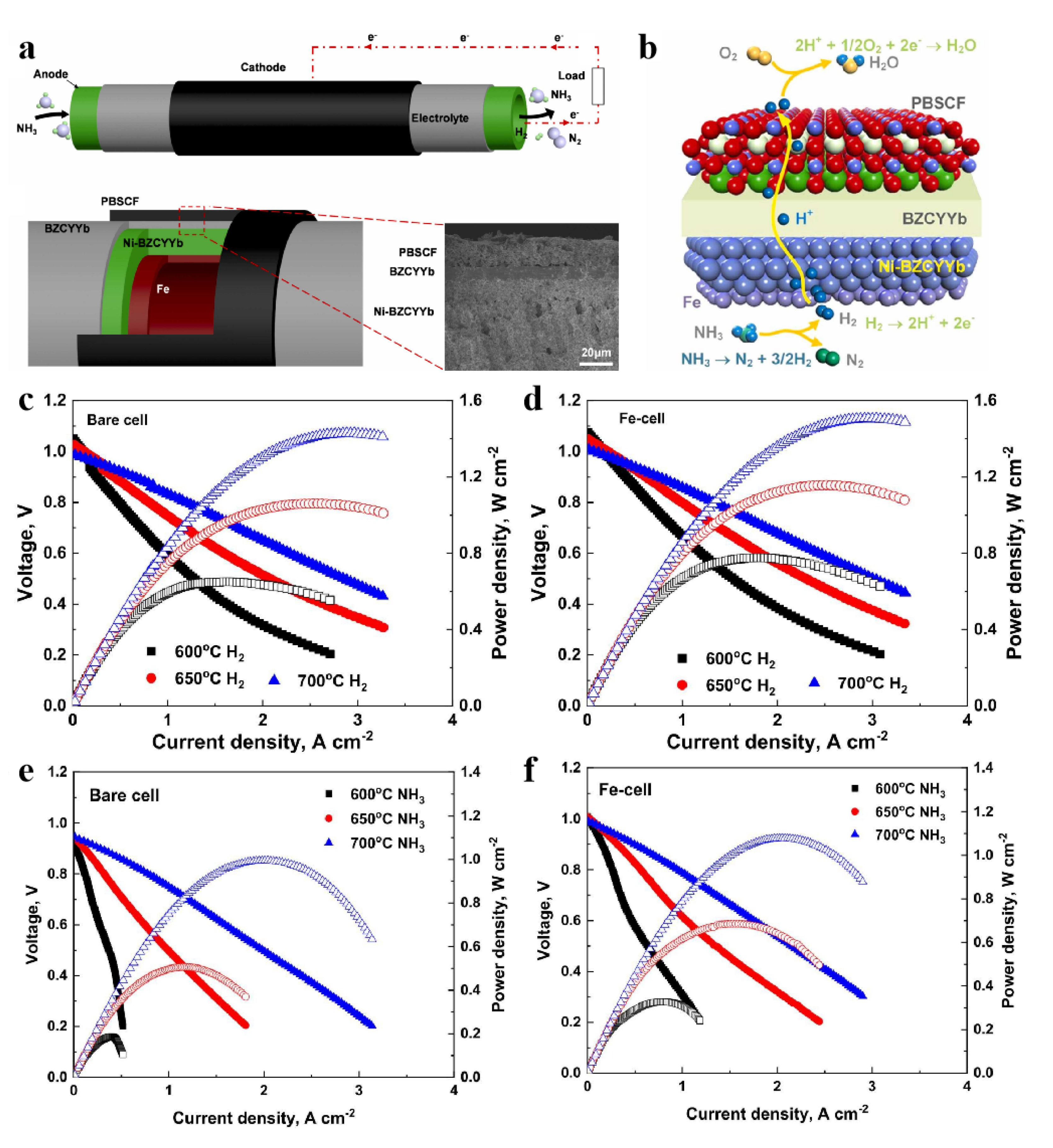
The in–situ growth approach has not been reported in the PEMFC. Its organic polymer membrane and inorganic electrodes are not directly connected by chemical bonds. Pan et al. [21] achieved direct conversion of hydrogen and ammonia fuels for power generation through tubular cells (Figure 4a), which feature an integrated Fe layer on the surface of ceramic electrolytes (Figure 4b). It maintains a stable open-circuit voltage (OCV) when the fuel changes from hydrogen to ammonia (Figure 4c–f). This is associated with high ammonia conversion efficiency (91.5%) at 700 °C.

2.3. Integrated Bipolar Plate–Electrode

Recently, bipolar plates (BP) incorporating porous materials, such as metals and graphene foams, have been proposed as distributors for hydrogen and oxygen distribution. These materials are not only controllable in geometric structure (pore shapes and porosity) but also show excellent performance in terms of heat distribution [22,23]. The integrated structure of the bipolar plate–electrode (BP–E) provides superior water management, heat transfer, and gas distribution. Among these, the electrode (E) includes a pure gas diffusion layer (GDL) and a gas diffusion layer/microporous layer (MPL) [24,25,26,27,28]. Zhang et al. [27] recently investigated a metal foam for an integrated porous BP–GDL through simulation, which significantly decreases the concentration loss due to the enhanced oxygen transfer compared to the conventional channel–rib BP+GDL. Jiao et al. [28] also fabricated a metal foam BP–E integrated design that eliminates the interfacial transport resistance between BP and electrodes, achieving a lightweight structure and preventing cracking of the MEA.
In addition, a waved corrugated mesh for the anode and a straight corrugated mesh for the cathode, both with CB–MPL, were investigated in the MEA to mitigate water flooding and reduce contact resistance [29]. Cho and Sung et al. [30] further achieved a unified flow field and gas diffusion layer through the use of graphene foam (GF), which provides a new design for the integration of bipolar plates and the MEA, as depicted in Figure 5a. The power density has a close correlation with the thickness, and it can achieve 0.9 W/cm2 when the thickness of GF is 200 μm, as shown in Figure 5b, resulting in an 82% reduction in the cell thickness. This structure could improve the uniform distribution of current density (Figure 5c) and prevent the obvious pressure drop (Figure 5d). However, it is susceptible to electrochemical corrosion, especially in an acidic atmosphere. Moreover, its stiffness is considerably lower than that of conventional graphite and alloy bipolar plates. Consequently, there is a necessity for coating materials and coating technologies to effectively enhance long-term running stability. On the other hand, enhancement processes should be used to avoid the deformation of BP–E, like chemical additives and physical compression.
Moreover, the gas diffusion, thermal distribution, and water management capabilities of metal foams (MFs) also surpass those of traditional graphite flow channels in BPs. Yang et al. [26] utilized 3D printing technology to precisely manufacture metal foams with graded pore structures, which could increase water discharge by 14.1% and decrease the pressure drop by two-thirds. Consequently, the maximum power density of PEMFCs was improved by 9.5%. Meanwhile, they also discovered that MFs are able to reduce the temperature by 8.4 °C in air-cooled PEMFCs [25]. This not only improves the electrochemical performance but also decreases the compression work compared to conventional parallel flow fields. The porosity, pore density, and compression ratio of MFs have a significant influence on oxygen transport [24]. Both the coarse filament pores in low-porosity MFs and the fine filament pores in high-porosity MFs can produce longer oxygen residence times, thereby enhancing gas convection and the transfer area between the flow field and GDL.
Jiao et al. [31] reported a design for an electrode-flow field integration without a GDL (GDL-less), consisting of graphene-coated Ni foam (320 μm) and an ultra-thin carbon nanofiber film (9.1 μm) (Figure 6a,b). Compared with the obvious transport boundaries in the conventional channel–rib configuration, the GDL-less design has shorter transport pathways and ensures uniform gas distribution, leading to significantly lower concentration resistance (Figure 6c–f). It can achieve a peak volumetric power density of 9.8 kW/L, which is considerably higher than that of 5.4 kW/L in the Toyota second-gen MIRAI (Figure 6g). The design also boasts satisfactory corrosion resistance and hydrophobicity, enhancing its durability. The integrated fuel cell paves the way for applications in sustainable power supply systems for bio-wearable sensors. Chen et al. [32] have assembled a metal hydrogel as the anode in a biofuel cell and utilize ascorbic acid (AA) from human sweat as the fuel. It attained a maximum output power density of 35 μW/cm2 and operated for 30 days without any decrease in performance.
Proton Exchange Membrane Electrolyzers (PEMECs) perform the reverse electrochemical reactions of PEMFCs, where water is oxidized at the anode (OER), producing protons, which cross the PEM and are reduced at the cathode to H2. PEMECs commonly use liquid water feed on the anode and typically operate in the 25–120 degree Celsius range, producing pressurized hydrogen (10–50 bar) directly in-stack [33,34]. Due to their compactness, fast dynamic response, and ability to deliver high-purity and pressurized hydrogen, PEMECs are pivotal for renewable-based hydrogen production pathways [35]. Modern commercial PEM electrolyzers run in the 2–5 A/cm2 range at cell voltages typically between 1.6–2.0 V, with stack electrical efficiencies around 60–80%. Large-scale deployment is growing rapidly, and the electrolyzer manufacturing capacity and projects have expanded rapidly in recent years. However, despite architectural similarities to PEM fuel cells, PEMECs impose distinct materials, manufacturing, and operational constraints—notably a highly oxidative anode environment, liquid feed, pressure operation, and H2 crossover—which change what “integration” practically means for electrolyzers versus fuel cells.
Yasutake et al. provide a representative demonstration of such catalyst-integrated gas diffusion electrodes (GDEs) for PEMWE [11]. Integrated flow-field/BP/GDL structures—including metal foam flow fields and porous BP–GDL monoliths—offer superior two-phase transport and thermal management, both critical to PEMECs, where liquid water and oxygen must be managed and heat must be removed efficiently. They found that the oxygen evolution reaction (OER) anode, which operates under strongly oxidative, often acidic conditions, causes carbon-based supports commonly used in PEMFC cathodes to corrode under OER conditions, motivating titanium (Ti)-based porous transport layers and corrosion-resistant coatings/supports for PEMEC anodes. Additionally, the anode is liquid-fed and produces rapidly evolving O2 bubbles. The pore architecture, flow-field design, and surface wettability must be engineered to facilitate continuous liquid removal and gas release—requirements that differ from gas-fed PEMFC catalyst layers [36].
Fan et al. [37] offer a detailed roadmap for bridging the gap between highly active oxygen–reduction reaction (ORR) catalysts, as characterized in RDE tests, and their practical performance in MEAs, emphasizing that catalyst intrinsic activity alone is not sufficient without engineered layers and interfacial control. Lim et al. [38] report on protonated phosphonic-acid electrodes that maintain proton conduction under high temperatures and low humidity, showcasing robust MEA performance suitable for heavy-duty vehicle applications. Tang et al. [39] introduce phosphoric-acid (PA)-doped intrinsically ultramicroporous membranes that allow for stable fuel-cell operation from −20 °C to 200 °C, effectively tackling challenges related to PA retention and extending operational ranges. Lee et al. [40] further enhance high-temperature performance by creating a self-assembled network polymer electrolyte membrane that combines p-PBI with cerium hydrogen phosphate, supporting stable fuel-cell operation at 250 °C with outstanding thermal stability. In the alkaline domain, Wang et al. [41] establish poly(aryl piperidinium) membranes and ionomers with high hydroxide conductivity and chemical stability, enabling hydroxide-exchange MEAs that facilitate PGM-free cathode strategies. Complementing this, Adabi et al. [42] demonstrate record-level power densities and durability using commercial Fe–N–C cathode electrocatalysts in AEMFCs, proving that PGM-free catalysts can achieve practical MEA performance when paired with compatible ionomers and electrode engineering. Collectively, these contributions underscore that breakthroughs in catalyst intrinsic activity, electrode ionomer chemistry, and membrane architecture must be integrated through deliberate MEA and catalyst-layer engineering to achieve real device-level performance.
However, adhesive processes, while low-cost and scalable, frequently encounter durability issues; in-situ growth methods ensure intimate interfaces but necessitate advanced manufacturing infrastructure; and bipolar plate–electrode integration leads to compact designs with lower interfacial resistance but raises concerns about material costs and corrosion under operating conditions. According to the DOE 2030/2040 targets, the EU Hydrogen Strategy, and IEA hydrogen roadmaps, no single approach is adequate. Hence, hybrid strategies are essential to balance performance, manufacturability, and industrial feasibility.

3. Summary and Perspectives

Traditional catalyst-coated substrate (CCS) and catalyst-coated membrane (CCM) processes suffer from serious interfacial issues, further resulting in multi-mass-transfer problems, which make it difficult to meet the target requirements of next-generation electrical equipment. This study addresses the long-term goal of achieving high power and light weight for PEMFC stacks. A summary of various integrated approaches involving the MEA, electrode, and bipolar plate is provided in Table 1.
The integrated design and process can solve the interface problems between BP and GDL, GDL and CL, and CL and PEM. Recently, many researchers have studied fabrication processes and in situ growth methods to achieve GDL-less and integrated membranes/electrodes. While the illustrated approaches highlight significant scientific advancements, scaling them up to industrial production presents major challenges. These include the high cost of iridium-based catalysts and titanium porous transport layers, the necessity of validating durability under intermittent renewable power operation, and the manufacturing complexity of porous bipolar plates and integrated MEAs. Recent DOE H2NEW reports and IEA hydrogen roadmaps further underscore that industrial feasibility necessitates reducing component costs, enhancing long-term stability, and developing standardized accelerated stress testing protocols for commercial adoption.
Meanwhile, further research should prioritize enhancing the durability of integrated electrodes under dynamic cycling, reducing the utilization of iridium and titanium to meet large-scale cost targets, ensuring mechanical reliability during stack-level scale-up, and integrating novel materials such as reinforced membranes with ePTFE supports, self-assembled network polymer electrolytes capable of operating at 250 °C, and advanced low-Ir OER catalysts.
In the future, it is valuable to explore new materials and in situ growth methods to manufacture integrated electricity equipment. Meanwhile, the advanced mechanical interpretation and characterization techniques are crucial to achieving their high efficiency, light weight, and reliability.

Author Contributions

J.Z. and R.D.: writing, literature review, and summarization; Y.W., C.M., Z.S. and Y.S.: writing, review & editing; S.M.H. and Z.J.: writing, review & editing, manuscript modification. All authors have read and agreed to the published version of the manuscript.

Funding

This work was funded through the National Natural Science Foundation of China (52402107) and the Department of Science & Technology of Shandong Province (ZR2023QB116). The author also thanks the support provided by the Foreign Experts Program of the Ministry of Human Resources and Social Security of the People’s Republic of China (H20240296).

Data Availability Statement

No new data were created or analyzed in this study.

Conflicts of Interest

The authors declare no conflict of interest.

References

  1. Rekker, S.; Chen, G.W.; Heede, R.; Ives, M.C.; Wade, B.; Greig, C. Evaluating fossil fuel companies’ alignment with 1.5 °C climate pathways. Nat. Clim. Change 2023, 13, 927–934. [Google Scholar] [CrossRef]
  2. Bergh, J.V.D.; Beers, C.V.; King, L.C. Climate activists–rethink fossil–fuel subsidy cuts. Nature 2023, 617, 465. [Google Scholar] [CrossRef] [PubMed]
  3. Schrotenboer, A.H.; Veenstra, A.A.; Broek, M.A.U.H.; Ursavas, E. A Green Hydrogen Energy System: Optimal control strategies for integrated hydrogen storage and power generation with wind energy. Renew. Sustain. Energy Rev. 2022, 168, 112744. [Google Scholar] [CrossRef]
  4. Qu, E.; Hao, X.; Xiao, M.; Han, D.; Huang, S.; Huang, Z.; Wang, S.; Meng, Y. Proton exchange membranes for high temperature proton exchange membrane fuel cells: Challenges and perspectives. J. Power Sources 2022, 533, 231386. [Google Scholar] [CrossRef]
  5. Liu, Y.; Chen, Y.; Ming, J.; Chen, L.; Shu, C.; Qu, T.; Tan, Q.; Liu, Y.; Asefa, T. Harvesting waste heat energy by promoting H+-ion concentration difference with a fuel cell structure. Nano Energy 2019, 57, 101–107. [Google Scholar] [CrossRef]
  6. Jaouen, F. Enabling low-cost and sustainable fuel cells. Nat. Mater. 2022, 21, 733–735. [Google Scholar] [CrossRef]
  7. Introducing the All–New Toyota MIRAI. Toyota Europe Newsroom. 2020. Available online: https://newsroom.toyota.eu/introducing–the–all–new–toyota–MIRAI/ (accessed on 2 January 2025).
  8. Full Specs of Toyota MIRAI 2021. Toyota USA. 2020. Available online: https://www.toyota.com/MIRAI/features/mileage_estimates/3002/3003 (accessed on 2 January 2025).
  9. Li, Y.; Zhu, E.; Yu, J.; Yu, J.; Yang, J.; Liu, W.; Cui, X.; Yang, X.; Zhang, Y.; Xu, M. Pt–Ni nanoparticles electrodeposited on rGO/CFP as high-performance integrated electrode for methanol oxidation. Int. J. Hydrogen Energy 2022, 47, 23957–23970. [Google Scholar] [CrossRef]
  10. Wang, Y.; Wu, M.M.; Wang, K.; Chen, J.W.; Yu, T.W.; Song, S.Q. Fe3O4@N–doped interconnected hierarchical porous carbon and its 3D integrated electrode for oxygen reduction in acidic media. Adv. Sci. 2020, 7, 2000407. [Google Scholar]
  11. Yasutake, M.; Kawachino, D.; Noda, Z.; Matsuda, J.; Lyth, S.; Ito, K.; Hayashi, A.; Sasaki, K. Catalyst–integrated gas diffusion electrodes for polymer electrolyte membrane water electrolysis: Porous titanium sheets with nanostructured TiO2 surfaces decorated with Ir electrocatalysts. J. Electrochem. Soc. 2020, 167, 124523. [Google Scholar] [CrossRef]
  12. Wang, C.; Lee, K.; Liu, C.P.; Kulkarni, D.; Atanassov, P.; Peng, X.; Zenyuk, I.V. Design of PEM water electrolysers with low iridium loading. Int. Mater. Rev. 2024, 69, 3–18. [Google Scholar] [CrossRef]
  13. Ferner, K.J.; Litster, S. Composite anode for PEM water electrolyzers: Lowering iridium loadings and reducing material costs with a conductive addi-tive. ACS Appl. Energy Mater. 2024, 7, 8124–8135. [Google Scholar] [CrossRef] [PubMed]
  14. Delikaya, Ö.; Bevilacqua, N.; Eifert, L.; Kunz, U.; Zeis, R.; Roth, C. Porous electrospun carbon nanofibers network as an integrated electrode@gas diffusion layer for high temperature polymer electrolyte membrane fuel cells. Electrochim. Acta 2020, 345, 136192. [Google Scholar] [CrossRef]
  15. Xing, Y.; Liu, L.; Fu, Z.; Li, Y.; Li, H. Reinforced integrated membrane electrode assembly based on ionomer wet-binding and ePTFE reinforcement strategy for proton exchange membrane fuel cells. Int. J. Hydrogen Energy 2023, 50, 79–90. [Google Scholar] [CrossRef]
  16. Ji, Z.; Huang, Y.; Chen, Q.; An, J.; Hao, D.; Shen, Z.; Ma, C.; Wang, Y. The fabrication of integrated proton exchange membrane fuel cells: Excellent mechanical strength and electrochemical performance. Int. J. Hydrogen Energy 2024, 65, 158–163. [Google Scholar] [CrossRef]
  17. Liu, Y.; Li, X.; Liu, Y.; Kou, W.; Shen, W.; He, G. Promoting opposite diffusion and efficient conversion of polysulfides in Trap FexC–Doped asymmetric porous membranes as integrated electrodes. Chem. Eng. J. 2020, 382, 122858. [Google Scholar] [CrossRef]
  18. Zeng, L.; Zhao, T. Integrated inorganic membrane electrode assembly with layered double hydroxides as ionic conductors for anion exchange membrane water electrolysis. Nano Energy 2015, 11, 110–118. [Google Scholar] [CrossRef]
  19. Wan, L.; Pang, M.; Le, J.; Xu, Z.; Zhou, H.; Xu, Q.; Wang, B. Oriented intergrowth of the catalyst layer in membrane electrode assembly for alkaline water electrolysis. Nat. Commun. 2022, 13, 7956. [Google Scholar] [CrossRef]
  20. Wang, Q.; Wu, Q.; Zhao, M.; Lu, S.; Liang, D. Prussian blue analogue based integrated membrane electrodes for desalination and selective removal of ammonium ions in a rocking-chair capacitive deionization. Chem. Eng. J. 2024, 482, 148923. [Google Scholar] [CrossRef]
  21. Pan, Y.; Zhang, H.; Xu, K.; Zhou, Y.; Zhao, B.; Yuan, W.; Sasaki, K.; Choi, Y.; Chen, Y.; Liu, M. A high-performance and durable direct NH3 tubular protonic ceramic fuel cell integrated with an internal catalyst layer. Appl. Catal. B Environ. 2022, 306, 121071. [Google Scholar] [CrossRef]
  22. Srouji, A.; Zheng, L.; Dross, R.; Turhan, A.; Mench, M. Ultra-high current density water management in polymer electrolyte fuel cell with porous metallic flow field. J. Power Sources 2013, 239, 433–442. [Google Scholar] [CrossRef]
  23. Yuan, W.; Tang, Y.; Yang, X.; Wan, Z. Porous metal materials for polymer electrolyte membrane fuel cells—A review. Appl. Energy 2012, 94, 309–329. [Google Scholar] [CrossRef]
  24. Suo, M.; Sun, K.; Chen, R.; Che, Z.; Zeng, Z.; Li, Q.; Tao, X.; Wang, T. Oxygen transport in proton exchange membrane fuel cells with metal foam flow fields. J. Power Sources 2022, 521, 230937. [Google Scholar] [CrossRef]
  25. Wan, Z.; Yan, H.; Sun, Y.; Yang, C.; Chen, X.; Kong, X.; Chen, Y.; Tu, Z.; Wang, X. Thermal management improvement of air-cooled proton exchange membrane fuel cell by using metal foam flow field. Appl. Energy 2023, 333, 120642. [Google Scholar] [CrossRef]
  26. Sun, Y.; Lin, Y.; Wan, Z.; Wang, Q.; Yang, C.; Yin, W.; Qiu, T. Water management and performance enhancement in proton exchange membrane fuel cell through metal foam flow field with hierarchical pore structure. Chem. Eng. J. 2024, 494, 152944. [Google Scholar] [CrossRef]
  27. Zhang, G.; Qu, Z.; Wang, Y. Proton exchange membrane fuel cell of integrated porous bipolar plate–gas diffusion layer structure: Entire morphology simulation. eTransportation 2023, 17, 100250. [Google Scholar] [CrossRef]
  28. Jiao, K.; Xuan, J.; Du, Q.; Bao, Z.; Xie, B.; Wang, B.; Zhao, Y.; Fan, L.; Wang, H.; Hou, Z.; et al. Designing the next generation of proton-exchange membrane fuel cells. Nature 2021, 595, 361–369. [Google Scholar] [CrossRef]
  29. Tanaka, S.; Shudo, T. Corrugated mesh flow channel and novel microporous layers for reducing flooding and resistance in gas diffusion layer-less polymer electrolyte fuel cells. J. Power Sources 2014, 268, 183–193. [Google Scholar] [CrossRef]
  30. Park, J.E.; Lim, J.; Lim, M.S.; Kim, S.; Kim, O.-H.; Lee, D.W.; Lee, J.H.; Cho, Y.-H.; Sung, Y.-E. Gas diffusion layer/flow-field unified membrane-electrode assembly in fuel cell using graphene foam. Electrochim. Acta 2019, 323, 134808. [Google Scholar] [CrossRef]
  31. Tongsh, C.; Wu, S.; Jiao, K.; Huo, W.; Du, Q.; Park, J.W.; Xuan, J.; Wang, H.; Brandon, N.P.; Guiver, M.D. Fuel cell stack redesign and component integration radically increase power density. Joule 2023, 8, 175–192. [Google Scholar] [CrossRef]
  32. Chen, Y.; Wan, X.; Li, G.; Ye, J.; Gao, J.; Wen, D. Metal hydrogel–based integrated wearable biofuel cell for self–powered epidermal sweat biomarker monitoring. Adv. Funct. Mater. 2024, 34, 2404329. [Google Scholar] [CrossRef]
  33. Ahmad Kamaroddin, M.F.; Sabli, N.; Tuan Abdullah, T.A.; Siajam, S.I.; Abdullah, L.C.; Abdul Jalil, A.; Ahmad, A. Mem-brane-Based Electrolysis for Hydrogen Production: A Review. Membranes 2021, 11, 810. [Google Scholar] [CrossRef] [PubMed]
  34. Wang, Y.; Pang, Y.; Xu, H.; Martinez, A.; Chen, K.S. PEM Fuel cell and electrolysis cell technologies and hydrogen infrastructure development—A review. Energy Environ. Sci. 2022, 15, 2288–2328. [Google Scholar] [CrossRef]
  35. Badgett, A.; Brauch, J.; Thatte, A.; Rubin, R.; Skangos, C.; Wang, X.; Ahluwalia, R.; Pivovar, B.; Ruth, M. Updated Manufactured Cost Analysis for Proton Exchange Membrane Water Electrolyzers; No. NREL/TP-6A20-87625; National Renewable Energy Laboratory (NREL): Golden, CO, USA, 2024. [Google Scholar]
  36. Chen, L.; Wang, Z.; Sun, C.; Zhu, H.; Xia, Y.; Hu, G.; Fang, B. Water management capacity of metal foam flow field for PEMFC under flooding situation. Micromachines 2023, 14, 1224. [Google Scholar] [CrossRef] [PubMed]
  37. Fan, J.; Chen, M.; Zhao, Z.; Zhang, Z.; Ye, S.; Xu, S.; Wang, H.; Li, H. Bridging the gap between highly active oxygen reduction reaction catalysts and effective catalyst layers for proton exchange membrane fuel cells. Nat. Energy 2021, 6, 475–486. [Google Scholar] [CrossRef]
  38. Lim, K.H.; Lee, A.S.; Atanasov, V.; Kerres, J.; Park, E.J.; Adhikari, S.; Maurya, S.; Manriquez, L.D.; Jung, J.; Fujimoto, C.; et al. Protonated phosphonic acid electrodes for high power heavy-duty vehicle fuel cells. Nat. Energy 2022, 7, 248–259. [Google Scholar] [CrossRef]
  39. Tang, H.; Geng, K.; Wu, L.; Liu, J.; Chen, Z.; You, W.; Yan, F.; Guiver, M.D.; Li, N. Fuel cells with an operational range of −20 °C to 200 °C enabled by phosphoric acid-doped in-trinsically ultramicroporous membranes. Nat. Energy 2022, 7, 153–162. [Google Scholar] [CrossRef]
  40. Lee, S.; Seong, J.G.; Jo, Y.; Hwang, S.J.; Gwak, G.; Park, Y.; Kim, Y.C.; Lim, K.H.; Park, H.Y.; Jang, J.H.; et al. Self-assembled network polymer electrolyte membranes for application in fuel cells at 250 °C. Nat. Energy 2024, 9, 849–861. [Google Scholar] [CrossRef]
  41. Wang, J.; Zhao, Y.; Setzler, B.P.; Rojas-Carbonell, S.; Ben Yehuda, C.; Amel, A.; Page, M.; Wang, L.; Hu, K.; Shi, L.; et al. Poly(aryl piperidinium) membranes and ionomers for hydroxide exchange membrane fuel cells. Nat. Energy 2019, 4, 392–398. [Google Scholar] [CrossRef]
  42. Adabi, H.; Shakouri, A.; Ul Hassan, N.; Varcoe, J.R.; Zulevi, B.; Serov, A.; Regalbuto, J.R.; Mustain, W.E. High-performing commercial Fe–N–C cathode electrocatalyst for anion-exchange membrane fuel cells. Nat. Energy 2021, 6, 834–843. [Google Scholar] [CrossRef]
  43. Zhan, R.; Wang, Y.; Ni, M.; Zhang, G.; Du, Q.; Jiao, K. Three-dimensional simulation of solid oxide fuel cell with metal foam as cathode flow distributor. Int. J. Hydrogen Energy 2020, 45, 6897–6911. [Google Scholar] [CrossRef]
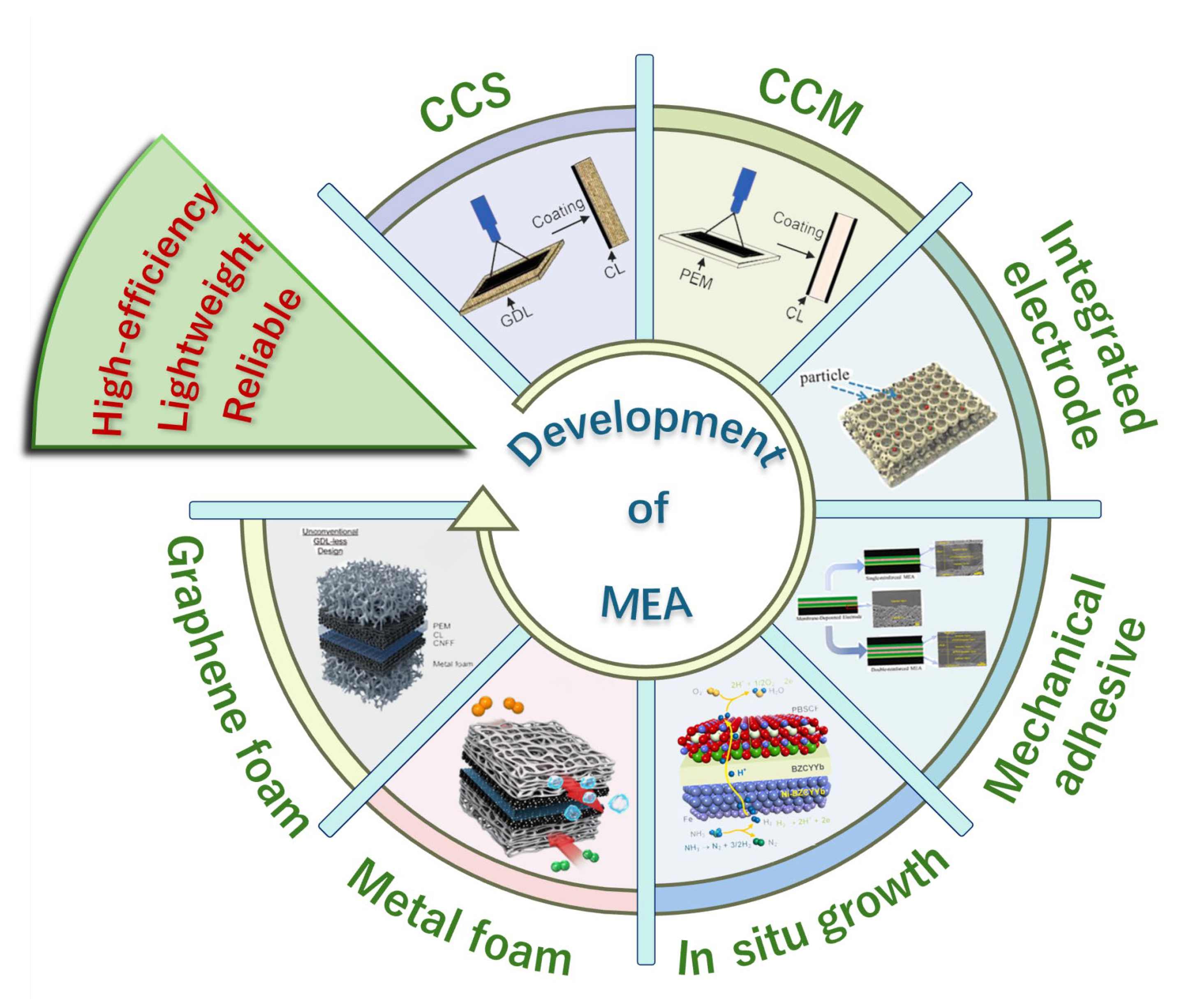
Figure 1. The structural development of a single PEMFC and electrolyzers.
Energies 18 05319 g001
Figure 2. (a) Synthesis of Fe3O4 by electrophoresis; (b) synthetic protocol of ordered, interconnected Fe3O4@NC/NHPC electrode; (c) microstructure of electrodes; (d) ORR activity of Fe3O4@NC/NHPC electrodes in O2-saturated 0.5 M H2SO4 solution; (e) the schematic illustrations of electron and mass transfer paths in different electrode systems [10].
Energies 18 05319 g002
Figure 3. (a) Synthesis process of integrated electrolyte/electrode; (b) cross-section of a ZnHCF–coated electrode [20].
Energies 18 05319 g003
Figure 4. (a) Schematic of a tubular cell using direct ammonia as the fuel; (b) schematic of the inner architecture of the tube and a scanning electron micrograph of the actual cell, consisting of a Ni–BZCYYb anode, a BZCYYb electrolyte, and a PBSCF cathode; electrochemical performances of the tubular cells, (c,d) typical I–V–P curves of the bare cell and Fe-cell in pure hydrogen; (e,f) typical I–V–P curves of the bare cell and Fe-cell in pure ammonia [21].
Energies 18 05319 g004
Figure 5. (a) Graphene foam for the integrated gas diffusion layer/flow field of PEMFC; (b) the PEMFC performance with different thicknesses of graphene foam; (c) the distribution of current density; and (d) the pressure drop of graphene foam PEMFC [30].
Energies 18 05319 g005
Figure 6. (a) Conventional channel–rib configuration and (b) GDL-less design of PEMFC; (c) polarization curves, (d) Ohmic resistance, (e) activation resistance, and (f) concentration resistance of GDL-less, metal foam, and parallel flow field PEMFC; (g) comparison of volumetric power density of commercial, GDL-less fuel cell stacks, and future trends (* including endplates; ** excluding endplates) [31].
Energies 18 05319 g006
Table 1. A summary of different integrated approaches.
CategoryKey MethodFabrication/Integration ApproachElectrochemical PerformanceAdvantagesLimitations
Integrated ElectrodePt–Ni/rGO/CFP electrodeposited [9]; FeO4 @N–carbon 3D electrode [10]; Porous CNF network electrode [14]Electrochemical deposition; templated growth; electrospinning+carbonizationORR activity improved, current densities > 100 mA/cm2 in acidic media; enhanced methanol oxidation performanceHigh surface area, catalyst utilization, improved mass transportComplex synthesis, scaling challenges, durability under cycling
Catalyst-integrated GDEsTi-sheet with nanostructured TiO–Ir catalyst [11]; Graphene foam GDL/flow-field unified MEA [30]Catalyst directly integrated with porous metallic or carbon scaffoldPEM water electrolysis: >2 A/cm2 at ~1.8–2.0 V; PEMFC: ~0.7 W/cm2Reduced interfacial resistance, robust structureIr/Pt loading high; cost; long-term stability
Integrated MEAs (membrane–electrode)ePTFE reinforced wet-bonding MEA [15]; Mechanical-strengthened integrated PEMFC [16]; Inorganic LDH-based AEM MEA [18]; Catalyst intergrowth MEA for AEM electrolysis [19]Wet-bonding ionomer + ePTFE reinforcement; direct deposition; LDH as ionic conductor; in-situ catalyst layer growthPEMFCs: peak power ~1.0–1.5 W/cm2; AEM electrolysis: >1 A/cm2 at ~1.9 VStrong interfacial bonding, reduced ohmic loss, improved durabilityProcess reproducibility, complex layer control, scale-up barriers
Integrated Functional Membranes/Hybrid ElectrodesTrap FeₓC porous membrane as electrode [17]; Prussian blue analogue integrated MEA for desalination [20]; NH3 ceramic fuel cell with internal catalyst [21]Asymmetric porous membranes; electrochemical intercalation electrodes; internal catalyst layerHigh selectivity (desalination); NH3 ceramic FC current > 0.5 A/cm2 at 600 °CMulti-function integration, reduced system complexityApplication-specific, materials stability, limited scalability
Integrated Bipolar Plate–Electrode/Flow-fieldPorous metal foams as flow field [22,23,24,25,26,43]; Porous bipolar plate–GDL unified structure [27]; Corrugated mesh + MPL [29]Metal foams, porous alloys, mesh with hierarchical pores; co-design with GDLPEMFC: power density > 1.0 W/cm2 with improved water/thermal management; enhanced flooding mitigationBetter mass/heat transport, lighter stack, simplified designCost of porous metals, mechanical durability, corrosion
System-level IntegrationToyota Mirai stack design [7,8,28]; Joule (2024) stack redesign for high power density [37]Compact integration of MEA, BPP, manifold redesign; thinner membranes, reduced inactive volumeToyota Mirai: ~3.1 kW/L stack power density; Joule (2024): >6 kW/LHigh stack-level efficiency, reduced system footprintManufacturing complexity, reliability, thermal/water management
Special ApplicationsWearable hydrogel-integrated biofuel cell [38]Metal hydrogel integrated with bioelectrodesPowering biosensors continuously from sweat metabolitesFlexible, biocompatible, self-poweredLow absolute power density, niche application
Disclaimer/Publisher’s Note: The statements, opinions and data contained in all publications are solely those of the individual author(s) and contributor(s) and not of MDPI and/or the editor(s). MDPI and/or the editor(s) disclaim responsibility for any injury to people or property resulting from any ideas, methods, instructions or products referred to in the content.