Article

Multi-Parameter Optimization Design of the Impeller for a Hydrogen Liquefaction Turbine Expander

1
Key Laboratory of Liquefied Natural Gas and Low Carbon Technology, China National Offshore Oil Corporation, Beijing 100028, China
2
College of Mechanical and Transportation Engineering, China University of Petroleum, Beijing 102249, China
*
Authors to whom correspondence should be addressed.
Energies 2025, 18(19), 5142; https://doi.org/10.3390/en18195142 (registering DOI)
Submission received: 15 August 2025 / Revised: 12 September 2025 / Accepted: 24 September 2025 / Published: 27 September 2025
(This article belongs to the Section A5: Hydrogen Energy)

Abstract

This study employs a combined approach of theoretical calculation and numerical simulation to systematically optimize the impeller of a turbine expander, the core component of a 10-ton/day hydrogen liquefaction system. First, based on thermodynamic analysis and one-dimensional calculations, a three-factor four-level orthogonal experiment optimizes the parameters of reaction degree, radius ratio, and blade height ratio. Building upon this foundation, the influence of two-dimensional meridional profiles on impeller efficiency is investigated to establish design criteria. Subsequently, the effects of three-dimensional parameters including tip clearance, blade count, and blade thickness on performance are analyzed. Finally, the impact of rotational speed and flow rate on efficiency is explored, identifying high-efficiency operational ranges. Through multi-parameter collaborative optimization, an impeller configuration achieving low outlet temperature (53.67 K) and high efficiency (about 93.6%) is obtained, providing critical references for designing high-efficiency turbine expanders in hydrogen liquefaction systems.

1. Introduction

Hydrogen energy, with its advantages of zero pollution, high calorific value, and abundant resources, is regarded as a key component of future clean energy systems [1,2]. However, its large-scale application is hindered by the low volumetric energy density of hydrogen and the safety risks associated with high-pressure transportation [3]. In this context, liquid hydrogen (LH2) has emerged as the most promising solution for large-scale, long-distance transportation due to its high energy density, playing a critical role in advancing the hydrogen energy industry chain [4].
The mainstream hydrogen liquefaction processes currently include the Linde–Hampson (L-H) cycle [5,6], the helium expansion refrigeration cycle [7,8], and the hydrogen expansion refrigeration cycle [9,10]. The L-H cycle has become largely obsolete due to its high energy consumption. Today, it is mainly limited to early experimental studies or micro-scale applications [11]. The helium expansion refrigeration cycle is based on the helium reverse Brayton cycle. It is primarily suitable for small-to-medium-scale plants (≤2.5 t/d), but is rarely applied in large-scale systems [12,13]. Medium-to-large-scale hydrogen liquefaction facilities (≥5 t/d) predominantly employ hydrogen expansion refrigeration cycles, particularly Claude cycles. The liquid nitrogen-precooled single-pressure Claude cycle exhibits relatively high specific power consumption. However, the optimized dual-pressure Claude process, as proposed by Baker et al., significantly reduces energy consumption [14]. As a result, it has become the mainstream technology for large-scale plants, such as Linde’s 4.4 t/d Ingolstadt facility [15]. Emerging processes, such as the Joule–Brayton (J-B) cycle, theoretically offer additional potential for energy reduction. However, their complex system design, high capital costs, and lack of technological maturity have so far prevented practical implementation [16,17].
As the core component of cryogenic systems, the performance of cryogenic expanders plays a crucial role in determining liquefaction efficiency. Consequently, their optimization has become a focus of intensive research [18]. In efforts to enhance performance, Song et al. [19] and Huang et al. [20] conducted blade optimization studies, with particular emphasis on mitigating vortex and cavitation phenomena in hydraulic turbine draft tubes. Fiachi et al. [21] developed a 50 kW radial-flow turbine model achieving 70–80% efficiency, with secondary flow losses representing the dominant factor. Jumonville et al. [22] employed CFD to investigate the internal flow characteristics of guide vanes and impellers. Their study demonstrated that numerical analysis is cost-effective and highly reproducible, while effectively capturing complex internal flow fields and identifying major loss sources such as nozzle boundary layer losses, rotor incidence losses, and tip clearance losses. Persky et al. [23] compared six loss models and found that passage losses (85.76%) and tip clearance losses (14.24%) were the dominant factors. Zhou et al. [7] utilized loss models to compare hydrogen and helium turbine performance, showing that adjustable guide vanes could improve radial-inflow turbine efficiency by up to 60%. Zhu et al. [8] designed a two-stage series-connected helium turbine expander based on the reverse Brayton cycle, achieving a hydrogen liquefaction capacity of 1.7 TPD with a pressure ratio of 8.32. Numerical and experimental validation confirmed its high efficiency, with an isentropic efficiency of 76.8–80.5% and a 31 K temperature drop. The results showed less than 10% deviation from simulations, meeting the stringent design requirements for cryogenic applications. While existing research on helium turbines has proposed various design schemes, these approaches cannot be directly applied to hydrogen systems due to the substantial differences in their thermodynamic and physical properties. Furthermore, many of the current optimization studies for hydrogen expanders tend to concentrate on isolated parameters or individual design aspects. In contrast, achieving high efficiency in hydrogen expanders necessitates a holistic strategy that integrates multi-parameter and synergistic optimization [24,25].
Given this context, this study focuses on the turbine expander for a 10-ton/day hydrogen liquefaction system (Figure 1), with particular emphasis on the optimization design of key parameters for its impeller. A combined approach of theoretical calculation and simulation modeling was employed to systematically investigate the influence of three critical design parameters—reaction degree, radius ratio, and blade height ratio—on efficiency characteristics. Building upon these results, further analysis was conducted on structural parameters including tip clearance, blade number, and blade thickness, as well as operational parameters such as rotational speed and flow rate, to evaluate their impact on the optimized impeller’s performance. Simulation results demonstrate that the optimized hydrogen turbine expander achieves isentropic efficiency significantly exceeding the 85% technical requirement. This work not only provides theoretical foundations and design guidelines for high-performance hydrogen turbine expanders, but also offers insights applicable to the optimization of turbomachinery operating with other cryogenic working fluids.

2. The Design of the Turbine Expander Impeller

The expansion end constitutes the most critical component of a turbine expander, defining the working fluid’s flow path where dynamic design is paramount. Hydrogen turbine expanders should evolve toward high performance, efficiency, and extended operational cycles. This study focuses on optimizing the flow passage design of Turbine Expander 1 (Figure 1), encompassing both nozzle and impeller, with primary emphasis on impeller parameter optimization.
The design methodology proceed is illustrated in Figure 2. Initial parameters are selected based on design specifications. One-dimensional thermodynamic calculations are performed using expander inlet/outlet conditions. A four-level orthogonal array (Supplementary Materials) was employed with three key variables: reaction degree, radius ratio, and blade height ratio. Based on this approach, fundamental parameters such as the impeller inner and outer diameters, blade height, and nozzle dimensions were derived. Subsequently, a 3D model is developed in CFturbo 10.3, and CFD simulations are conducted to evaluate the impact of the three variables on the expander’s efficiency and outlet temperature. The results guide the optimal parameter selection and inform the preliminary 1D impeller design.
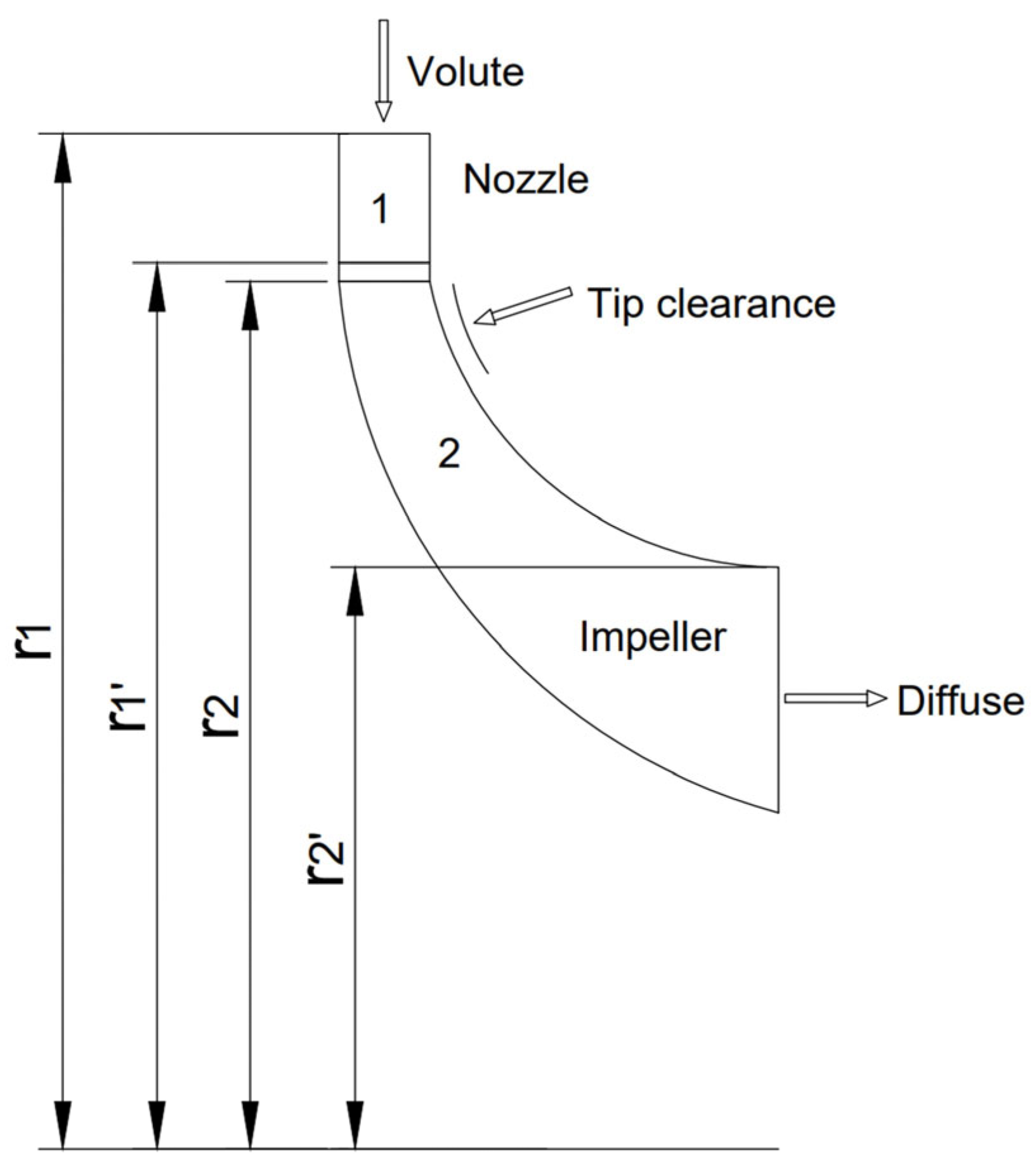
Subsequently, meridional profile analysis investigates its influence on impeller efficiency and internal flow characteristics to refine the 2D profile design. Finally, parametric studies on blade thickness, tip clearance, and blade number yield an optimized 3D impeller model maximizing efficiency. The complete design workflow and meridional profile configuration are illustrated in accompanying figures (Figure 3).

2.1. Calculation of Dimensional Parameters for Turbine Expander Impeller

One-dimensional thermodynamic calculations preliminarily determine key dimensional parameters including the impeller’s outer/inner diameters, blade height, and nozzle’s inner diameters. During this process, the reaction degree, radius ratio, and blade height ratio were selected as optimization variables, each assigned four discrete values. Using a three-factor four-level orthogonal array design (see Table S1), these calculations yield geometric modeling parameters—specifically impeller outer/inner diameters, blade height, rotational speed, and nozzle inner diameters. The governing equations for the thermodynamic calculations are provided in Supplementary Materials.
Based on computational results, the dimensions for the expander nozzle and impeller were determined. The seventh orthogonal experimental group yielded optimal efficiency, with detailed results presented in Table 1.

2.2. Modeling and Simulation

2.2.1. Modeling of the Nozzle and Impeller

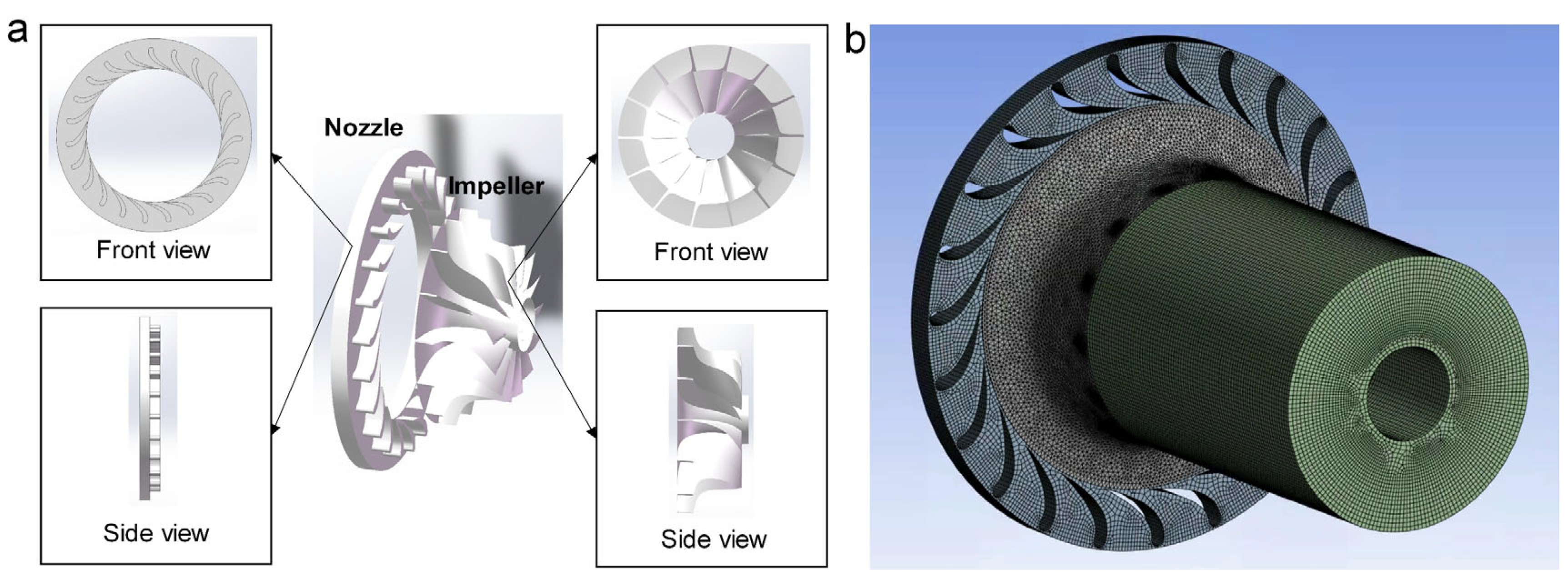
Three-dimensional models of the expander impeller and nozzle were constructed in CFturbo 10.3 (Figure 4a) using baseline dimensions from one-dimensional thermodynamic calculations. The fluid domains were extracted via Boolean operations and redefined using SpaceClaim’s structural data. An outlet extension was incorporated to prevent gas backflow. The meshing of the fluid domain achieves good mesh quality through automatic size matching, with compliant sections illustrated in Figure 4b.

2.2.2. Control Equations and Turbulence Models

The flow of hydrogen through a turbine expander is governed by the fundamental laws of mass, momentum, and energy conservation. Based on these physical principles, the continuity equation, momentum conservation equations, and energy equation can be derived. The continuity equation, established according to mass conservation, is expressed in Cartesian coordinates as:
ρ t + d i v ρ u = 0
Derived from Newton’s second law of motion, the momentum equations [27] along the X, Y, and Z axes in Cartesian coordinates are expressed as:
ρ u x t + d i v ρ u x u = F x ρ x + τ x x x + τ y x y + τ z x z
ρ u y t + d i v ρ u y u = F y ρ y + τ x y x + τ y y y + τ z y z
ρ u z t + d i v ρ u z u = F z ρ z + τ x z x + τ y z y + τ z z z
The momentum equations are described by the Navier–Stokes (N-S) equations, where terms τxx, τxy, and τxz represent molecular-derived surface viscous stresses. Fx, Fy, and Fz denote body forces. Since only gravity affects the expander model, these terms are set as Fx = 0, Fy = 0, Fz = −ρg. The energy equation is expressed as:
D D t e s = F b 1 v + 1 ρ d i v P · v + 1 ρ d i v k g r a d T + q
where e denotes specific internal energy (per unit mass) from random molecular motion, ρ represents fluid density, t is time, and v is the fluid velocity vector. The stress tensor P characterizes stresses—encompassing normal and shear stresses—acting on fluid elements.
The SST turbulence model combines the k-ϵ and k-ω models, making it well suited for capturing flow separation and vortices in rotating machinery. The k-ω model is effective for analyzing near-wall fluid motion, while the k-ϵ model is better for predicting fluid behavior away from walls [28,29]. This makes the SST model advantageous for analyzing the complex internal flow in cryogenic turbo-expander machinery. Total pressure and total temperature at the nozzle inlet were specified as boundary conditions. The boundary conditions can be expressed as:
Pin = constant, Tin = constant
where Pin and Tin represent the total pressure (Pa) and temperature (K) at the compressor inlet, respectively.
Static pressure at the outlet was set as the boundary condition.
Pout = constant
The nozzle domain was defined as stationary, while the impeller domain was set to rotating. All surfaces except interfaces and boundaries were specified as adiabatic no-slip walls. For CFD simulations of the turbine expander, residual convergence criteria were set to 10−6, with continuous monitoring of outlet enthalpy change, total pressure, exit temperature, and velocity distribution.
The isentropic efficiency η of the expander is defined as:
η = h i n h o u t h i n h o u t , i s
where hin is inlet total enthalpy of the expander, hout,is is isentropic outlet total enthalpy of the expander, hout is actual outlet total enthalpy of the expander.

2.2.3. Model Validation

To verify grid independence, a mesh-sensitivity analysis was performed using hydrogen as the working fluid. Under fixed boundary conditions, computational domains were discretized with progressively refined grids. As shown in Figure 5, when grid counts exceed 4 million, the influence of grid size becomes negligible: total efficiency stabilizes within ±0.2% and outlet temperature variations remain below 1%. Balancing computational accuracy and efficiency, a mesh configuration of 4 million cells per blade passage was selected for subsequent simulations. A comparison of our simulation results with those from other studies on turbine expanders (Table S3) further validates the reliability of the proposed model. Moreover, since our study focuses on a comparative analysis of different parameters, the SST turbulence model and boundary conditions were consistently employed across all cases, thereby ensuring the high reliability of the comparative results.

3. Result and Discussion

3.1. Simulation Results of Turbine Expanders Under Different One-Dimensional Design Parameter

This study employed an orthogonal experimental design with three key impeller parameters—reaction degree, radius ratio, and blade height ratio—as variables, each tested at four levels. Using an orthogonal matrix, preliminary impeller dimensions were first determined through 1D thermodynamic calculations. Subsequent 3D modeling and numerical simulations generated 16 datasets of efficiency and outlet temperature (Table 2). It can be observed that the efficiency loss of the turbine impeller ranges between 7% and 14%. The primary losses occur in the nozzle and impeller. The losses in the impeller are notably more intricate than those in the nozzle, encompassing incidence loss, passage loss, tip clearance loss, trailing edge loss, residual velocity loss and windage loss.
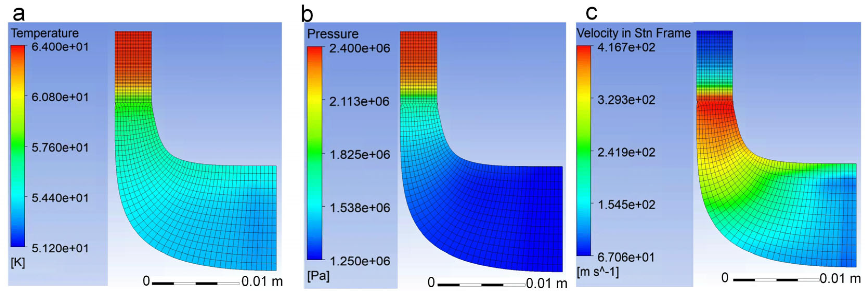
Figure 6 presents temperature, pressure, and velocity contours for group 7, revealing hydrogen’s thermodynamic evolution within the expander flow path (nozzle and rotor passages). Both temperature and pressure exhibit continuous declines along the flow direction due to adiabatic expansion converting thermal energy (enthalpy) into mechanical work, consistent with the first law of thermodynamics. Velocity increases sharply within the converging nozzle passages where thermal/pressure energy transforms into kinetic energy (Bernoulli’s principle). In contrast, velocity decreases in rotor passages as high-velocity flow impinges on blades, transferring kinetic energy into shaft work via flow redirection. Due to the high-speed rotation of the impeller, centrifugal force drives the gas flow outward, resulting in a higher flow velocity at the outer diameter compared to the inner diameter. The collision of the flow with the blades and the redirection of its motion lead to the conversion of kinetic energy into thermal energy, thereby causing the temperature at the impeller hub to be higher than that at the tip. This trend is consistent with the simulation results.
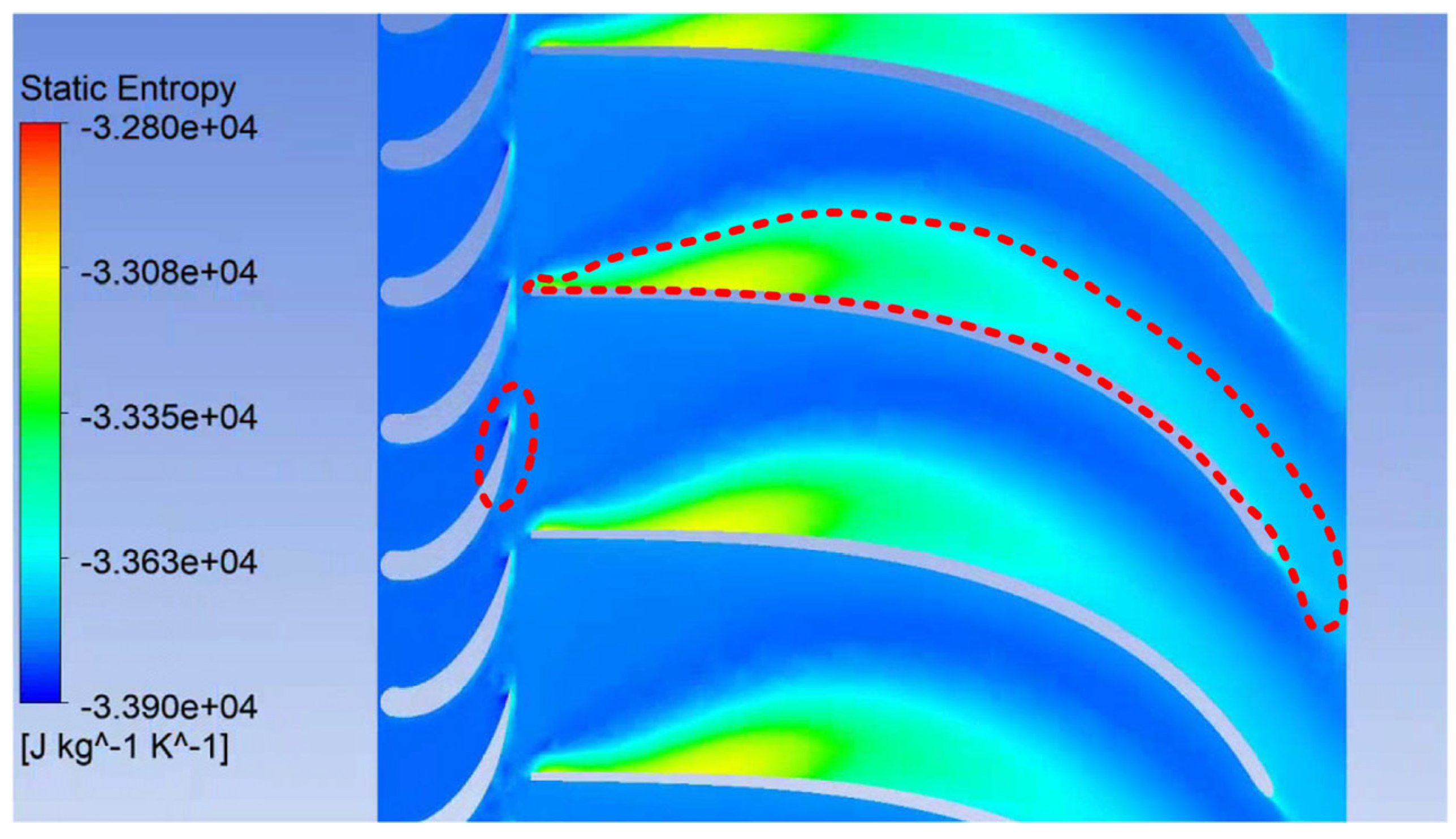
As illustrated in Figure 7, entropy generation is closely associated with flow separation and predominantly occurs in three regions: the junction between the nozzle outlet and the impeller inlet, the impeller tip region, and the mid-section of the flow passage. This phenomenon results from high flow velocities and increased shear forces near the blade tips, leading to significant energy loss. The tip clearance in the impeller enables flow leakage from the pressure side to the suction side. This leakage mixes with the main flow, enhancing shear effects and consequently elevating entropy production, which is most pronounced near the suction side. The majority of entropy is generated in the mid-portion of the impeller flow path, where the flow direction gradually shifts from radial to axial. During this transition, the flow velocity decreases while blade loading increases due to the pressure difference between the pressure and suction sides. Under these conditions, the leakage flow moves almost perpendicularly from the blade toward the suction side, forming large-scale vortices. These structures interact with the main flow, further amplifying entropy generation. Near the impeller outlet, the flow becomes predominantly axial, and tip leakage weakens while the flow velocity rises. This increase enhances shear effects near the impeller tip, resulting in notably higher entropy generation at the outlet.
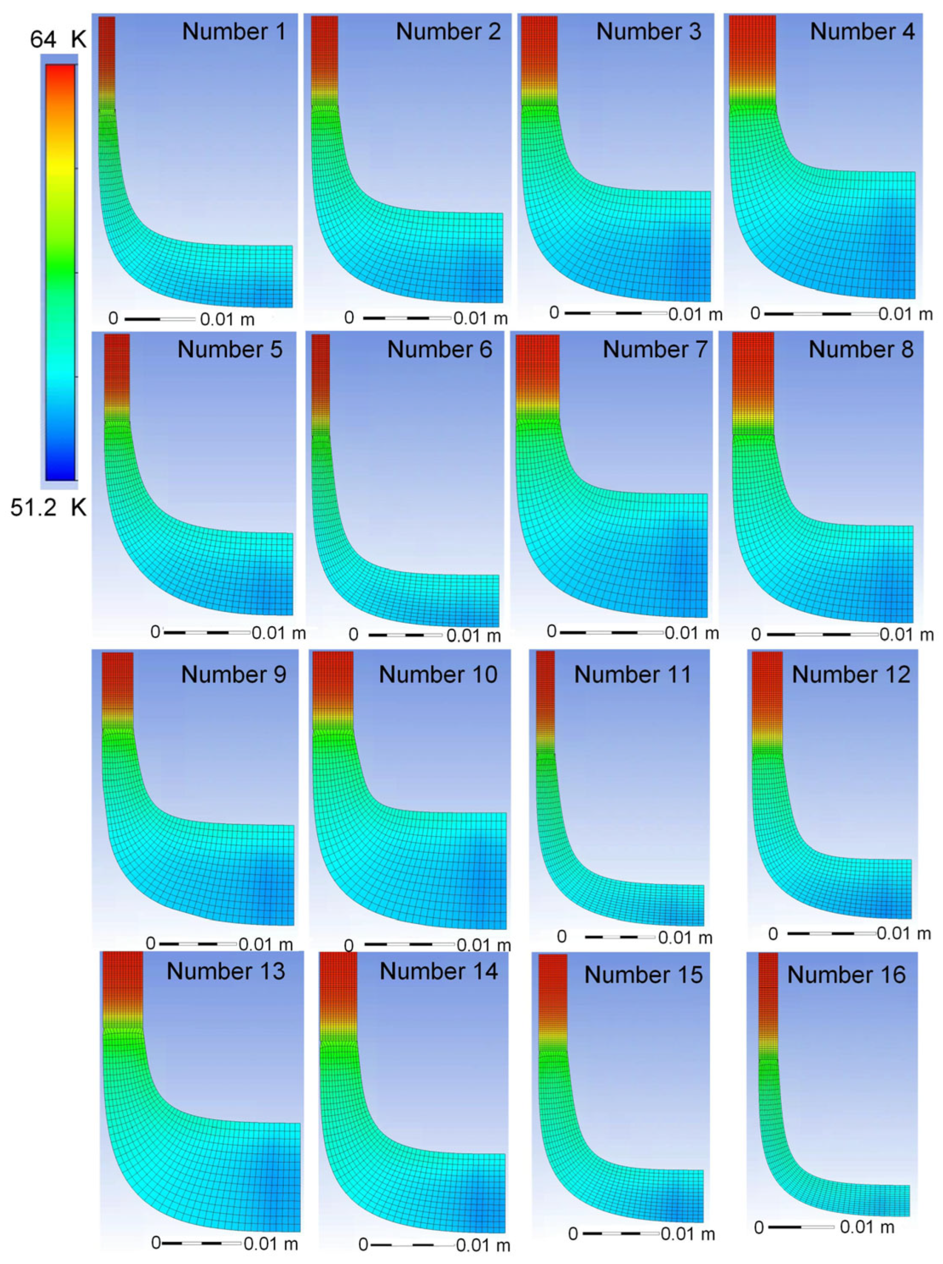
As shown in Figure 8, the gas temperature distributions along the meridional plane of hydrogen turbine impellers with different profiles exhibit a consistent trend, gradually decreasing from the inlet to the outlet. Correspondingly, the gas pressure also decreases progressively under different profiles (Figure S1). Moreover, the velocity increases within the nozzle region but gradually decreases within the impeller (Figure S2).
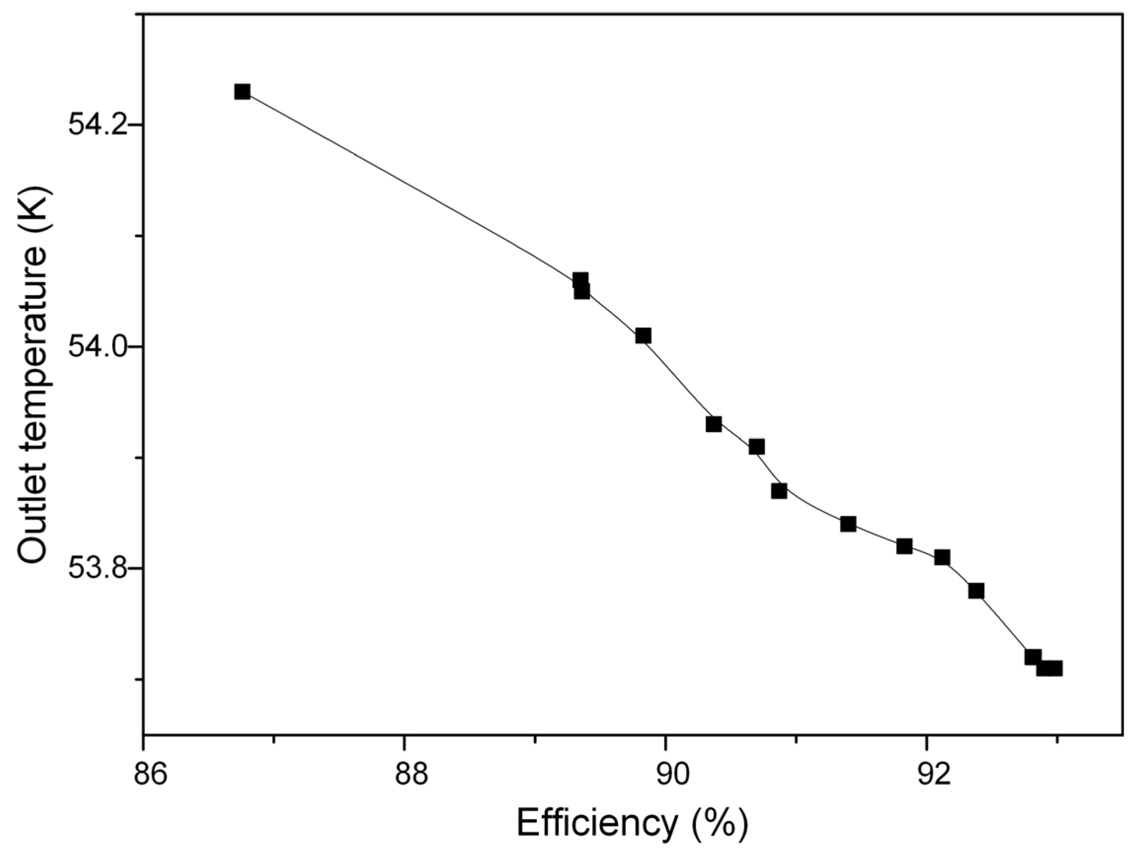
Isentropic efficiency analysis (Figure 9) demonstrates that under constant outlet pressure, lower exit temperatures reduce hydrogen enthalpy, thereby increasing available enthalpy drop and boosting efficiency. All configurations exceeded 85% efficiency, with peak values surpassing 92%.
Statistical evaluation of factor-level effects yielded the following observation. The reaction degree, defined as the ratio of the enthalpy drop across the rotor blades to the total enthalpy drop in the stator and rotor blades, exhibits a non-monotonic relationship with efficiency. Specifically, efficiency initially increases with rising reaction degree but decreases after exceeding an optimal point. This is because a moderate degree of reaction optimally balances fluid acceleration in the stator with work extraction in the rotor, whereas an excessively high reaction degree causes boundary layer separation and amplifies secondary flow losses. Balancing computational stability and efficiency performance, the optimal reaction degree was determined as 0.45 (Figure 10a).
Efficiency demonstrates a unimodal response to radius ratio variation: initially rising then declining, indicating an optimal value. This non-monotonic relationship arises from competing fluid dynamic effects. Smaller radius ratios increase centrifugal stresses and induce higher flow losses. In contrast, larger radius ratios reduce the work extraction capability because of insufficient flow turning. At the optimal radius ratio of 0.55, blade loading distribution achieves near-ideal incidence angles, minimizing boundary layer separation and passage vortices (Figure 10b).
Efficiency generally improves with increasing blade height ratio, primarily due to reduced secondary flow losses and enhanced flow guidance at higher aspect ratios (Figure 10c). However, higher blade height ratios introduce significant blade stress concentration and vibration risks. The optimal blade height ratio was determined as 0.09. The optimal configuration (reaction: 0.45, radius ratio: 0.50, blade height ratio: 0.09) is recommended as the validated design solution.

3.2. Analysis of the Influence of Meridional Profile on the Performance of Expander Impellers

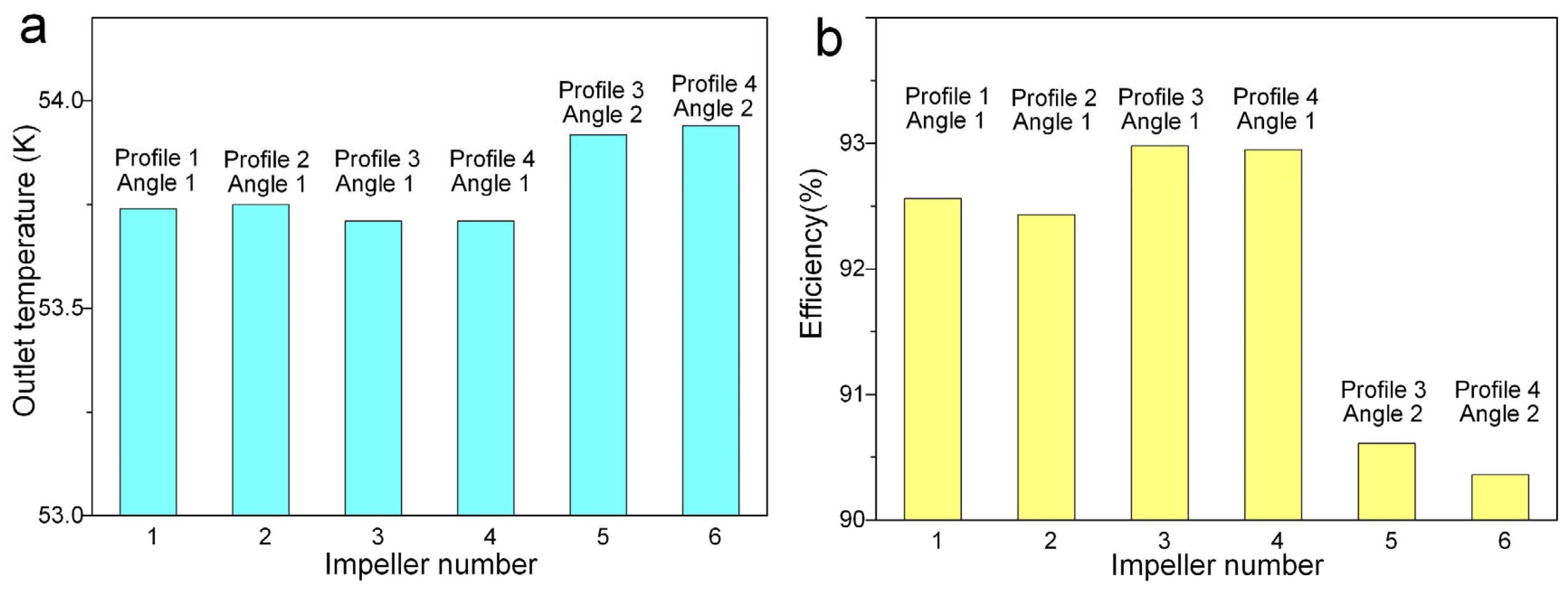
Based on the fundamental impeller dimensions (determined by parameters including the degree of reaction and radius ratio), this study systematically investigates the influence of 2D meridional flow path profiles on performance. Figure 11 shows that Profile 1 exhibits significant cross-sectional area variations at both the inlet and outlet, Profile 2 displays abrupt area changes at the inlet, while Profiles 3/4 maintain smooth transitions at the boundaries with linear mid-section progression. Figure 12 demonstrates that the expander impellers with Profiles 3/4 achieve lower outlet temperatures and higher efficiency. Flow field analyses (Figure 11 and Figure S3) reveal that Profiles 1/2 cause pronounced flow separation on the suction side, likely explaining their efficiency reduction. Therefore, optimal meridional flow path design should follow the progressive cross-sectional transition principle. This ensures smooth passage transitions and controlled area variation rates at inlet/outlet zones, thereby effectively reducing flow losses.
Building upon Profiles 3 and 4, this study further investigates the influence of blade deflection angle (Figure 11(c1,c2,d1,d2)). In Figure 11, the meridional profiles of the two impellers in Figure 11(c1,c2) are the same, but the latter adopts a larger deflection angle, and its efficiency is significantly reduced (Figure 12). Streamline analysis reveals that excessive deflection angles intensify gas impingement on the pressure side. This triggers localized rapid acceleration and deceleration cycles, which amplify energy dissipation through turbulent losses. This confirms that smooth meridional profile transitions and aerodynamically aligned blade deflection angles are essential for enhancing turbine expander efficiency.

3.3. Analysis of the Influence of Blade Parameters on the Performance of Expander Impellers

Following the establishment of the impeller’s aerodynamic baseline via integrated 1D/2D design principles, systematic parametric optimization identified blade count, thickness, and tip clearance as critical performance drivers. Figure 13 illustrates the impact of impeller blade number on the expander’s outlet temperature and isentropic efficiency. As the number of blades increases from 13 to 15, the outlet temperature progressively decreases while the efficiency correspondingly improves. This trend demonstrates that augmenting the blade number enhances flow guidance, reduces flow losses, and consequently improves energy conversion efficiency.
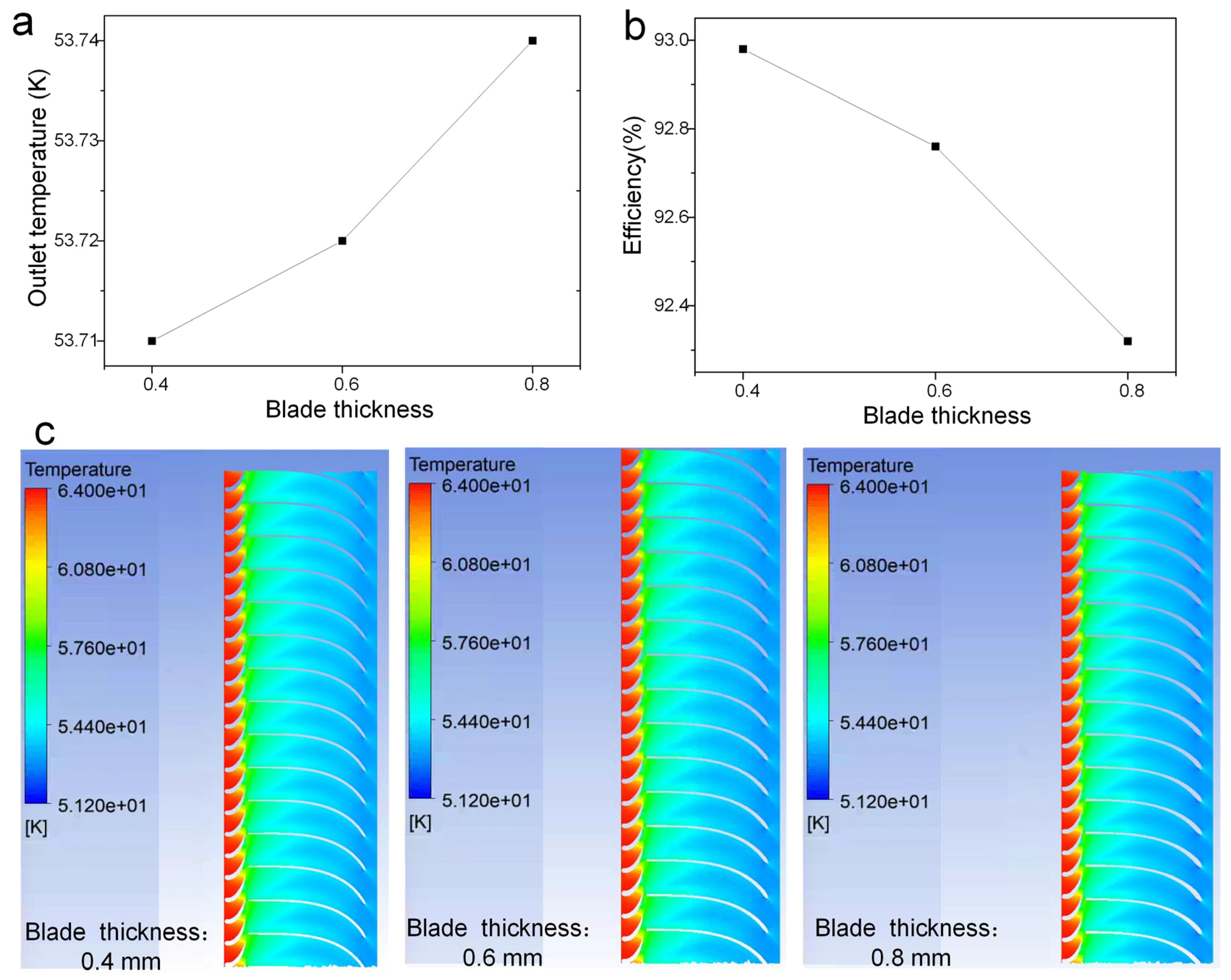
Figure 14 reveals that increasing blade thickness induces a slight rise in expander outlet temperature and a marginal efficiency reduction—specifically, a 0.6% efficiency decrease occurs as thickness escalates from 0.4 mm to 0.8 mm. While thin blades enhance aerodynamic performance, their inadequate strength compromises structural integrity, whereas thick profiles intensify flow losses.
Figure 15 illustrates the impact of tip clearance on hydrogen turbine expander efficiency and outlet temperature. Analysis reveals that as tip clearance increases from 0.16 mm to 0.34 mm, expander efficiency decreases by approximately 1%, while the average outlet temperature rises by ≈0.1 K. This is primarily attributed to enhanced leakage vortex development, which intensifies tip leakage flow and induces mixing losses, thereby degrading thermodynamic performance.

3.4. Analysis of the Influence of Operating Parameters Such as Rotational Speed and Flow Rate on the Performance of Expander Impellers

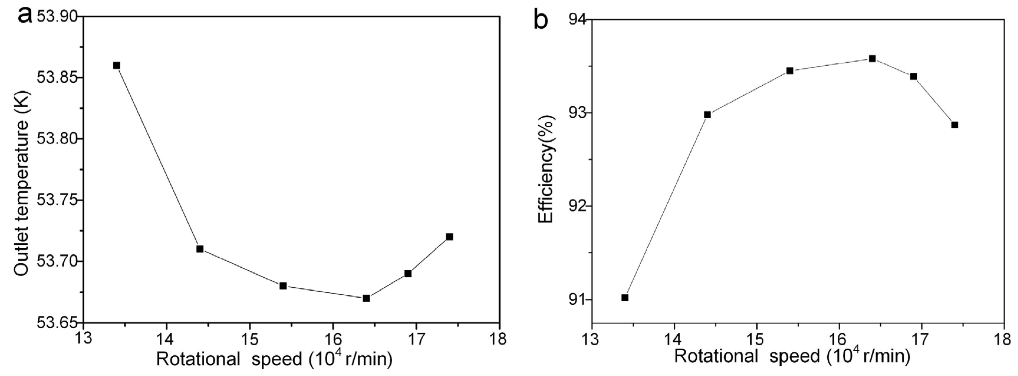
As illustrated in Figure 16, systematic analysis reveals a distinct high-efficiency operational zone for rotational speed effects on expander impeller performance. With increasing speed, the outlet temperature first decreases then rises, while efficiency peaks before declining. At 165,000 rpm, maximum efficiency coincides with minimal outlet temperature. Low-speed inefficiency stems from inadequate flow turning, whereas excessive speed induces shock losses and intensified secondary flows. Nevertheless, ultra-high speeds impose demanding bearing precision requirements, necessitating holistic evaluation of rotor-dynamic stability in design optimization.
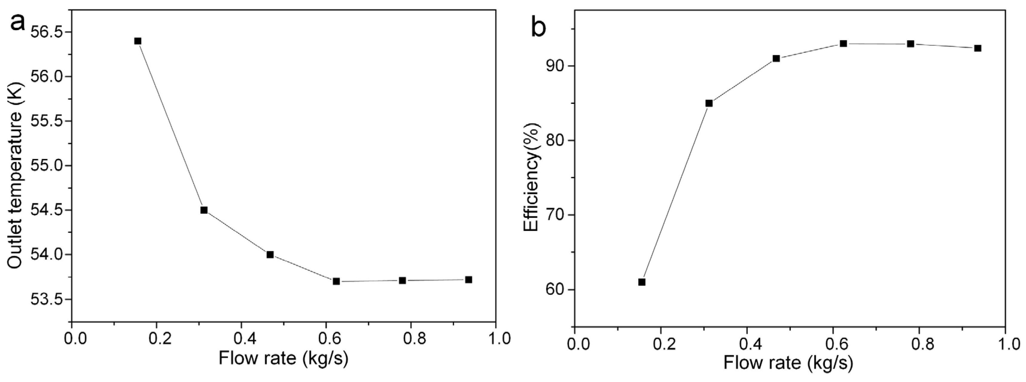
Figure 17 depicts variations in outlet temperature and isentropic efficiency of the turbine expander across mass flow rates. As flow increases, outlet temperature drops sharply before stabilizing, while isentropic efficiency rises rapidly and plateaus above 90% beyond 0.6 kg/s. The efficiency degradation at low flows maybe stems from boundary layer separation and secondary flow losses, demonstrating that coordinated optimization of flow coefficient and rotational speed governs hydrogen liquefaction efficiency.
As indicated by the aforementioned research, a comparative analysis of the optimal efficiency achieved by the impeller optimized in this study against those from other studies is presented in Table S3. The results demonstrate that the design obtained through multi-parameter cooperative optimization achieves a simulated isentropic efficiency of over 93.2%, which is competitive with known high-performance designs. However, this study relies on several assumed parameters in the one-dimensional thermodynamic analysis—such as the impeller speed coefficient and nozzle velocity coefficient—which still offer potential for further refinement. In addition, the rotational speed range of the hydrogen turbine expander in this study is between 60,000 and 160,000 rpm, thereby posing significant challenges in the mechanical design of components such as bearings. This study focuses on impeller design and optimization. Due to the limited system-level data, the overall impact of the optimized impeller on the hydrogen liquefaction system has not been fully evaluated, which is a limitation of this work. Future studies should integrate the optimized impeller into the full system to assess its effects on energy consumption, liquefaction efficiency, and cold energy recovery.

4. Conclusions

This study establishes an optimization framework for turbine expanders in 10-ton/day hydrogen liquefaction systems through computational analysis and numerical simulation. A three-factor, four-level orthogonal experiment identified the optimal one-dimensional parameters: reaction degree of 0.45, radius ratio of 0.50, and blade height ratio of 0.09. Based on these parameters, key dimensions (impeller inner/outer diameters) were determined, achieving >92% isentropic efficiency. Meridional Profiles 3/4 with smooth cross-sectional transitions demonstrated superior performance by reducing suction-side flow separation. Excessive blade deflection angles caused pressure-side impingement and efficiency loss. Three-dimensional parameter analysis shows that although there is a higher number of blades, thinner blades and smaller tip clearance can improve efficiency. However, these three cannot reach their limit values considering structural constraints. Operational studies confirmed peak efficiency at 165,000 rpm and stable >90% efficiency beyond 0.6 kg/s flow rate. This approach provides effective design guidelines for cryogenic turbomachinery.

Supplementary Materials

The following supporting information can be downloaded at: https://www.mdpi.com/article/10.3390/en18195142/s1, Table S1: Orthogonal Experimental design table; Table S2: Selected values of one-dimensional thermodynamic parameters; Table S3: The comparison with existing impeller design of hydrogen liquefaction expanders; Figure S1: Pressure cloud maps of different orthogonal experimental groups; Figure S2: Velocity cloud maps of different orthogonal experimental groups; Figure S3: Streamline diagram of turbine expander impellers with six different profiles. References [8,10,30,31,32,33,34] are cited in supplementary file.

Author Contributions

Conceptualization, X.Z.; Methodology, X.Z.; Software, P.L.; Validation, P.L.; Formal analysis, H.C.; Investigation, H.C. and J.Y.; Resources, P.L. and F.L.; Data curation, H.C. and F.L.; Writing—original draft, X.Z. and Z.Z.; Writing—review & editing, Z.Z. and K.W.; Visualization, F.L.; Supervision, Z.Z. and J.Y.; Project administration, Z.Z.; Funding acquisition, K.W. All authors have read and agreed to the published version of the manuscript.

Funding

This work was funded by Science Foundation of China University of Petroleum-Beijing (No. 2462025BJRC001).

Data Availability Statement

The original contributions presented in this study are included in the article/Supplementary Materials. Further inquiries can be directed to the corresponding author.

Conflicts of Interest

Authors Xiaohui Zhang, Hao Cheng, Fangqiu Li and Jiayi Yang were employed by the Key Laboratory of Liquefied Natural Gas and Low Carbon Technology, China National Offshore Oil Corporation. The remaining authors declare that the research was conducted in the absence of any commercial or financial relationships that could be construed as a potential conflict of interest.

References

  1. Chen, S.H.; Qiu, C.X.; Shen, Y.W.; Tao, X.; Gan, Z.H. Thermodynamic and economic analysis of new coupling processes with large-scale hydrogen liquefaction process and liquid air energy storage. Energy 2024, 286, 129563. [Google Scholar] [CrossRef]
  2. Faye, O.; Szpunar, J.A. An Efficient Way To Suppress the Competition between Adsorption of H2 and Desorption of nH2–Nb Complex from Graphene Sheet: A Promising Approach to H2 Storage. J. Phys. Chem. C 2018, 122, 28506–28517. [Google Scholar] [CrossRef]
  3. Zheng, J.P.; Chen, L.B.; Wang, J.; Xi, X.T.; Zhu, H.L.; Zhou, Y.; Wang, J.J. Thermodynamic analysis and comparison of four insulation schemes for liquid hydrogen storage tank. Energy Convers. Manag. 2019, 186, 526–534. [Google Scholar] [CrossRef]
  4. Teng, J.J.; Wang, K.; Zhu, S.L.; Bao, S.R.; Zhi, X.Q.; Zhang, X.B.; Qiu, L.M. Comparative study on thermodynamic performance of hydrogen liquefaction processes with various ortho-para hydrogen conversion methods. Energy 2023, 271, 127016. [Google Scholar] [CrossRef]
  5. Chang, H.M.; Ryu, K.N.; Baik, J.H. Thermodynamic design of hydrogen liquefaction systems with helium or neon Brayton refrigerator. Cryogenics 2018, 91, 68–76. [Google Scholar] [CrossRef]
  6. Asadnia, M.; Mehrpooya, M. A novel hydrogen liquefaction process configuration with combined mixed refrigerant systems. Int. J. Hydrogen Energy 2017, 42, 15564–15585. [Google Scholar] [CrossRef]
  7. Zhou, K.M.; Chen, L.; Li, S.F.; Zhao, K.; Zhang, Z.; Chen, S.T.; Hou, Y. Comparative analysis of energy losses in hydrogen and helium turbo-expanders for hydrogen liquefiers. Appl. Therm. Eng. 2023, 227, 120322. [Google Scholar] [CrossRef]
  8. Zhu, Z.C.; Lou, S.M.; Zhang, Y.M.; An, L.L.; Liu, Y.; Li, X.J. The design and research of two-stage series-connected helium turbine expanders for hydrogen liquefaction system. Appl. Therm. Eng. 2024, 249, 123396. [Google Scholar] [CrossRef]
  9. Yang, J.; Li, Y.Z.; Tan, H.B. Study on Performance Comparison of Two Hydrogen Liquefaction Processes Based on the Claude Cycle and the Brayton Refrigeration Cycle. Processes 2023, 11, 932. [Google Scholar] [CrossRef]
  10. Zhou, K.M.; Zhao, K.; Chen, L.; Zhang, Z.; Deng, K.Y.; Chen, S.T.; Hou, Y. High-efficiency control strategies of a hydrogen turbo-expander for a 5 t/d hydrogen liquefier. Energy 2024, 297, 131326. [Google Scholar] [CrossRef]
  11. Aasadnia, M.; Mehrpooya, M. Large-scale liquid hydrogen production methods and approaches: A review. Appl. Energy 2018, 212, 57–83. [Google Scholar] [CrossRef]
  12. Krasae-in, S.; Stang, J.H.; Neksa, P. Development of large-scale hydrogen liquefaction processes from 1898 to 2009. Int. J. Hydrogen Energy 2010, 35, 4524–4533. [Google Scholar] [CrossRef]
  13. Yuksel, Y.E.; Ozturk, M.; Dincer, I. Analysis and assessment of a novel hydrogen liquefaction process. Int. J. Hydrogen Energy 2017, 42, 11429–11438. [Google Scholar] [CrossRef]
  14. Baker, C.R.; Shaner, R.L. A study of the efficiency of hydrogen liquefaction. Int. J. Hydrogen Energy 1978, 3, 321–334. [Google Scholar] [CrossRef]
  15. Bracha, M.; Lorenz, G.; Patzelt, A.; Wanner, M. Large-scale hydrogen liquefaction in Germany. Linde-Rep. Sci. Technol. 1994, 19, 53–59. [Google Scholar] [CrossRef]
  16. Krasae-In, S.; Stang, J.H.; Neksa, P. Simulation on a proposed large-scale liquid hydrogen plant using a multi-component refrigerant refrigeration system. Int. J. Hydrogen Energy 2010, 35, 12531–12544. [Google Scholar] [CrossRef]
  17. Ansarinasab, H.; Mehrpooya, M.; Mohammadi, A. Advanced exergy and exergoeconomic analyses of a hydrogen liquefaction plant equipped with mixed refrigerant system. J. Clean. Prod. 2017, 144, 248–259. [Google Scholar] [CrossRef]
  18. Valenti, G.; Macchi, E. Proposal of an innovative, high-efficiency, large-scale hydrogen liquefier. Int. J. Hydrogen Energy 2008, 33, 3116–3121. [Google Scholar] [CrossRef]
  19. Song, P.; Sun, J.J.; Wang, K. Swirling and cavitating flow suppression in a cryogenic liquid turbine expander through geometric optimization. Proc. Inst. Mech. Eng. Part A-J. Power Energy 2015, 229, 628–646. [Google Scholar] [CrossRef]
  20. Huang, N.; Li, Z.L.; Zhu, B.S. Cavitating Flow Suppression in the Draft Tube of a Cryogenic Turbine Expander through Runner Optimization. Processes 2020, 8, 270. [Google Scholar] [CrossRef]
  21. Fiaschi, D.; Manfrida, G.; Maraschiello, F. Thermo-fluid dynamics preliminary design of turbo-expanders for ORC cycles. Appl. Energy 2012, 97, 601–608. [Google Scholar] [CrossRef]
  22. Jumonville, J. Tutorial on Cryogenic Turboexpanders; Texas A&M University, Turbomachinery Laboratory: College Station, TX, USA, 2010; Available online: https://hdl.handle.net/1969.1/163027 (accessed on 12 September 2025).
  23. Persky, R.; Sauret, E. Loss models for on and off-design performance of radial inflow turbomachinery. Appl. Therm. Eng. 2019, 150, 1066–1077. [Google Scholar] [CrossRef]
  24. Sun, Z.; Yao, Q.; Jin, H.; Xu, Y.; Hang, W.; Chen, H.; Li, K.; Shi, L.; Gu, J.; Zhang, Q.; et al. A novel in-situ sensor calibration method for building thermal systems based on virtual samples and autoencoder. Energy 2024, 297, 131314. [Google Scholar] [CrossRef]
  25. Li, L.; Xu, P.; Li, Q.H.; Yin, Z.C.; Zheng, R.Y.; Wu, J.F.; Bao, J.J.; Bai, W.Y.; Qi, H.; Tan, D.P. Multi-field coupling particle flow dynamic behaviors of the microreactor and ultrasonic control method. Powder Technol. 2025, 454, 120731. [Google Scholar] [CrossRef]
  26. Wang, H.; Yang, J.; Dong, X.; Guo, H.; Zhao, Y. Thermodynamic analysis and optimization of 10 t/d hydrogen liquefaction process. CIESC J. 2022, 73, 12. [Google Scholar] [CrossRef]
  27. Ferrario, F.; Busini, V. Statistical analysis of modelling approaches for CFD simulations of high-pressure natural gas releases. Results Eng. 2024, 21, 101770. [Google Scholar] [CrossRef]
  28. Menter, F.R. Review of the shear-stress transport turbulence model experience from an industrial perspective. Int. J. Comput. Fluid Dyn. 2009, 23, 305–316. [Google Scholar] [CrossRef]
  29. Li, X.M.; Li, J.; Pan, W.; Zou, Y.C.; Li, Q. Investigation on tip leakage flow characteristics of radial inflow micro turbine used in helium liquefying system. Int. J. Refrig. 2019, 98, 51–60. [Google Scholar] [CrossRef]
  30. Che, X.J.; Li, H.K.; Zhang, Z.N.; Chen, Y.B.; Cai, B.A.; Liu, K.X.; Cai, W.H. A novel optimum design method and performance analysis of cryogenic hydrogen turbo-expander for hydrogen liquefaction. Cryogenics 2025, 145, 103996. [Google Scholar] [CrossRef]
  31. Niu, B.; Chen, L.; Deng, K.; Wang, H.; Qu, J.; Li, S.; Zhang, Z.; Chen, S.; Hou, Y. Genetic algorithm based optimization design and coupling performance analysis of multi-stage series hydrogen turbo-expanders. Energy 2025, 335, 138128. [Google Scholar] [CrossRef]
  32. Zhou, K.M.; Chen, L.; Wang, H.D.; Deng, K.Y.; Zhang, Z.; Chen, S.T.; Hou, Y. Comparison of mean-line methods for hydrogen turbo-expanders in hydrogen liquefiers. Case Stud. Therm. Eng. 2024, 60, 104632. [Google Scholar] [CrossRef]
  33. Lim, H.; Seo, J.; Park, M.; Choi, B.; Park, J.; Bang, J.; Lee, D.; Kim, B.; Kim, S.; Lim, Y.; et al. A Numerical Study on Blade Design and Optimization of a Helium Expander for a Hydrogen Liquefaction Plant. Appl. Sci. 2022, 12, 1411. [Google Scholar] [CrossRef]
  34. Liu, H.M.; Zuo, J.S.; Qiu, S.; Liang, Y.W.; Ke, C.L.; Liu, L.Q.; Peng, N.; Xiong, L.Y.; Li, K.R.; Zhang, X.H. Simulative and experimental analysis of high-speed helium turbo-expanders in a 5t/day hydrogen liquefier. Int. J. Hydrogen Energy 2025, 133, 152–164. [Google Scholar] [CrossRef]
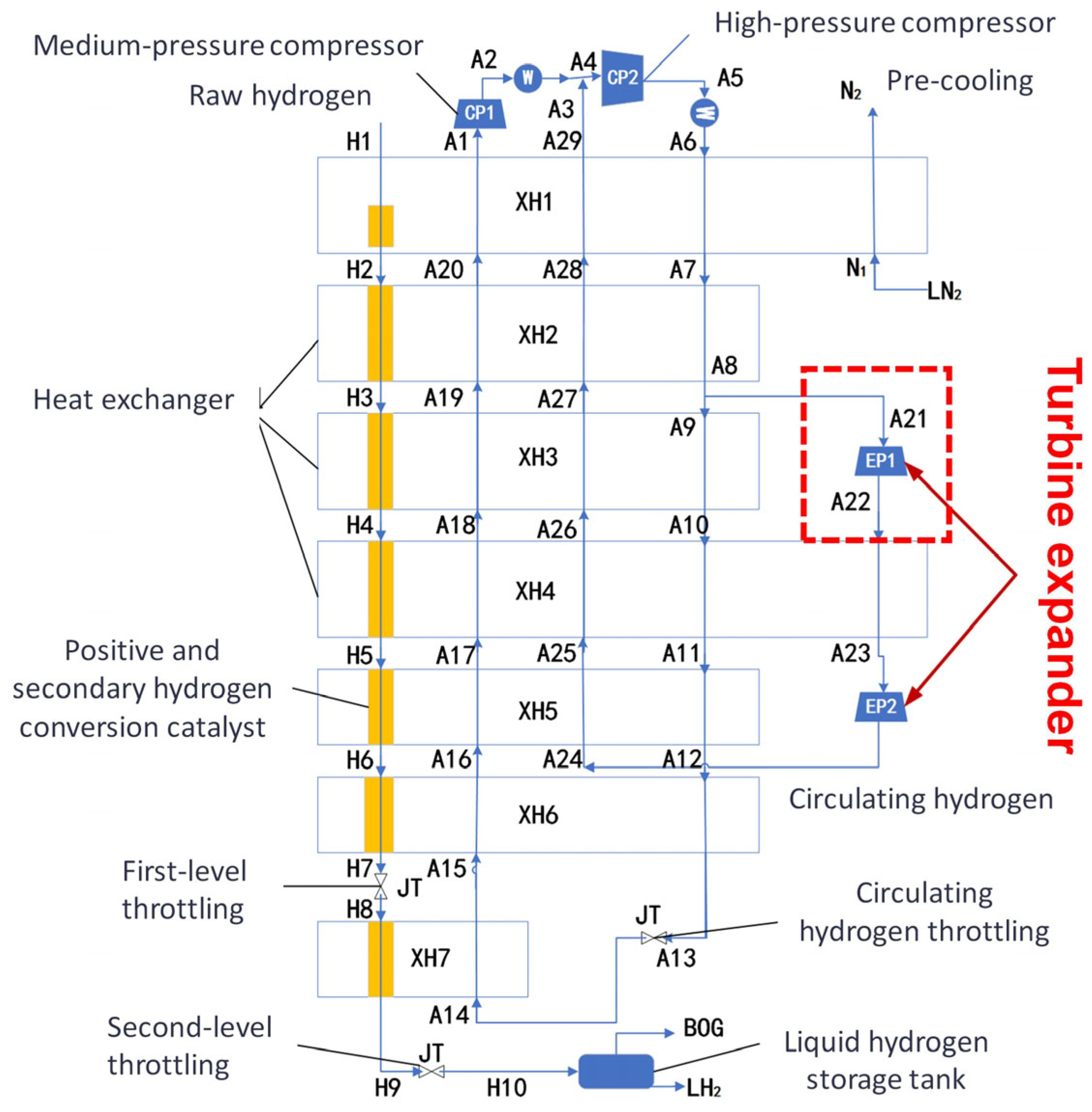
Figure 1. Dual-pressure Claude hydrogen liquefaction process [26].
Energies 18 05142 g001
Figure 2. The dynamic design process of the nozzle and impeller.
Energies 18 05142 g002
Figure 3. Schematic of the meridian plane of the expansion end [8].
Energies 18 05142 g003
Figure 4. (a) Nozzle and impeller of the turbine expander. (b) Calculation domain and grid of the turbine expander.
Energies 18 05142 g004
Figure 5. Grid independence verification.
Energies 18 05142 g005
Figure 6. The (a) temperature, (b) pressure and (c) velocity cloud maps of orthogonal experimental group 7.
Energies 18 05142 g006
Figure 7. The static entropy cloud map of orthogonal experimental group 7.
Energies 18 05142 g007
Figure 8. Temperature cloud maps of different orthogonal experimental groups.
Energies 18 05142 g008
Figure 9. The relationship between the efficiency and the outlet temperature of the turbine expander.
Energies 18 05142 g009
Figure 10. The relationship between (a) reaction degree, (b) radius ratio, (c) blade height ratio and the average efficiency of the turbine expander.
Energies 18 05142 g010
Figure 11. Simulation results for different profiles and different blade deflection angles. (a) Profile 1 with blade deflection angle 1; (b) Profile 2 with blade deflection angle 1; (c1) Profile 3 with blade deflection angle 1; (c2) Profile 3 with blade deflection angle 2; (d1) Profile 4 with blade deflection angle 1; (d2) Profile 4 with blade deflection angle 2 (each subfigure includes temperature distribution, cross-sectional area, and streamline diagrams).
Energies 18 05142 g011
Figure 12. (a) Outlet temperature and (b) efficiency of turbine expander impellers with different profiles.
Energies 18 05142 g012
Figure 13. The influence of the number of blades on the (a) outlet temperature and (b) efficiency of the turbine expander. (c) Temperature cloud maps of expanders under different numbers of impeller blades.
Energies 18 05142 g013
Figure 14. The influence of the blade thickness on the (a) outlet temperature and (b) efficiency of the turbine expander. (c) Temperature cloud maps of expanders under different blade thickness.
Energies 18 05142 g014
Figure 15. The influence of the blade tip clearance on the (a) outlet temperature and (b) efficiency of the turbine expander. (c) Temperature cloud maps of expanders under different blade tip clearance.
Energies 18 05142 g015
Figure 16. Effects of Rotational Speed on (a) Outlet Temperature and (b) Efficiency of the Turbine Expander.
Energies 18 05142 g016
Figure 17. Effects of flow rate on (a) Outlet Temperature and (b) Efficiency of the Turbine Expander.
Energies 18 05142 g017
Table 1. Basic dimensions of hydrogen turbine nozzles and impellers.
Design ParametersValueDesign ParametersValue
Impeller inlet diameter D1 (mm)49.6Nozzle outlet diameter Dn (mm)51.7
Impeller outlet outer diameter D2′ (mm)36.6Nozzle blade outer diameter D0 (mm)67.5
Impeller outlet inter diameter D2″ (mm)12.6Nozzle height lN (mm)4.2
Blade inlet height l1 (mm)4.3Nozzle blade outlet span tN (mm)7.1
Blade outlet height l2 (mm)12Nozzle blade chord length b (mm)11.8
Rotational speed (r/min)144,000Number of nozzles23
Number of blades14
Table 2. Simulation results of different orthogonal experimental groups.
NumberOutlet Temperature (K)Efficiency (%)NumberOutlet Temperature (K)Efficiency (%)
154.0589.36953.8192.12
253.9390.371053.7292.81
353.8491.401154.0189.83
453.7892.381253.8790.87
553.9190.701353.7292.81
654.0689.351453.7192.90
753.7192.981553.8291.83
853.7292.821654.2386.76
Disclaimer/Publisher’s Note: The statements, opinions and data contained in all publications are solely those of the individual author(s) and contributor(s) and not of MDPI and/or the editor(s). MDPI and/or the editor(s) disclaim responsibility for any injury to people or property resulting from any ideas, methods, instructions or products referred to in the content.