Article

A Comparative Analysis of Hydrogen Fuel Cells and Internal Combustion Engines Used for Service Operation Vessels Propulsion

by
Monika Bortnowska
* and
Arkadiusz Zmuda
*
Department of Naval Architecture and Shipbuilding, Faculty of Navigation, Maritime University of Szczecin, 70-500 Szczecin, Poland
*
Authors to whom correspondence should be addressed.
Energies 2025, 18(19), 5104; https://doi.org/10.3390/en18195104
Submission received: 16 August 2025 / Revised: 13 September 2025 / Accepted: 23 September 2025 / Published: 25 September 2025

Abstract

In response to the IMO’s decarbonisation strategy, hydrogen—especially green hydrogen—becomes a promising alternative fuel in shipping. This article provides a comparative analysis of two hydrogen propulsion technologies suitable for a service vessel (SOV) operating in offshore wind farms: hydrogen fuel cells and hydrogen-powered internal combustion engines. This study focuses on the use of liquid hydrogen (LH2) stored in cryogenic tanks and fuel cells as an alternative to the previously considered solution based on compressed hydrogen (CH2) stored in high-pressure cylinders (700 bar) and internal combustion engines. The research aims to examine the feasibility of a fully hydrogen-powered SOV energy system. The analyses showed that the use of liquefied hydrogen in SOVs leads to the threefold reduction in tank volume (1001 m3 LH2 vs. 3198 m3 CH2) and the weight of the storage system (243 t vs. 647 t). Despite this, neither of the technologies provides the expected 2-week autonomy of SOVs. LH2 storage allows for a maximum of 10 days of operation, which is still an improvement over the CH2 gas variant (3 days). The main reason for this is that hydrogen tanks can only be located on the open deck. Although hydrogen fuel cells take up on average 13.7% more space than internal combustion engines, they are lower (by an average of 24.3%) and weigh less (by an average of 50.6%), and their modular design facilitates optimal arrangement in the engine room. In addition, the elimination of the exhaust system and lubrication simplifies the engine room layout, reducing its weight and space requirements. Most importantly, however, the use of fuel cells eliminates exhaust gas emissions into the atmosphere.

1. Introduction

1.1. Research Background

The International Maritime Organisation’s (IMO) commitment to zero CO2 emissions from maritime transport by 2050 is a highly ambitious goal for this mode of transport [1]. The use of alternative fuels and zero-carbon fuels offers a path to achieving this goal, but this still poses significant technical, economic and logistical challenges associated with all alternative fuels and energy carriers. A DNV report from the end of 2024 [2] confirms a dynamic—more than double—increase in orders for ships powered by low- and zero-emission alternative fuels, from 130 orders in 2023 to 269 in 2024 (Figure 1).
To assess the transformation in shipping, it would be necessary to analyse the entire supply chain, from fuel production, through transport and storage, to disposal. At the stage of implementing new marine fuels, it is virtually impossible to analyse the entire path due to the multitude of unknowns and the need to make a number of assumptions and simplifications, e.g., regarding the costs of individual stages of the supply chain or the current price level of a fuel, which in fact result from the method of its extraction. Most of the currently existing green fuels, i.e., liquefied natural gas (LNG), liquefied petroleum gas (LPG) and ammonia, are fossil fuels, harmful to the environment. Therefore, a strategic solution will be to gradually switch exclusively to 100% green fuel, obtained, among other methods, from renewable energy sources. Hydrogen is, of course, one of the future zero-emission marine fuels.
Global demand for hydrogen reached 97 Mt in 2023, an increase of 2.5% compared to 2022, with the majority still covered by hydrogen produced from fossil fuels [3,4]. Green hydrogen is less available (production was less than 1 Mt in 2023) [3,4], and its production costs are high compared to grey and black hydrogen, but there are high hopes for its commercialisation and competitive prices. In Europe, the average cost of green hydrogen currently ranges from 4.5 ÷ 6.0 $/kg [5]. However, global production costs for green hydrogen (LCOH, Levelized Cost of Hydrogen) are expected to fall to 2.5 $/kg by 2030, according to ABI Research by D. Burge [6]. According to the same forecasts, by 2040, LCOH is expected to reach an even lower level, i.e., approx. 1.8 $/kg, mainly due to falling renewable energy prices, and by 2050, green LCOH is expected to reach a price of approx. 1.0 $/kg.
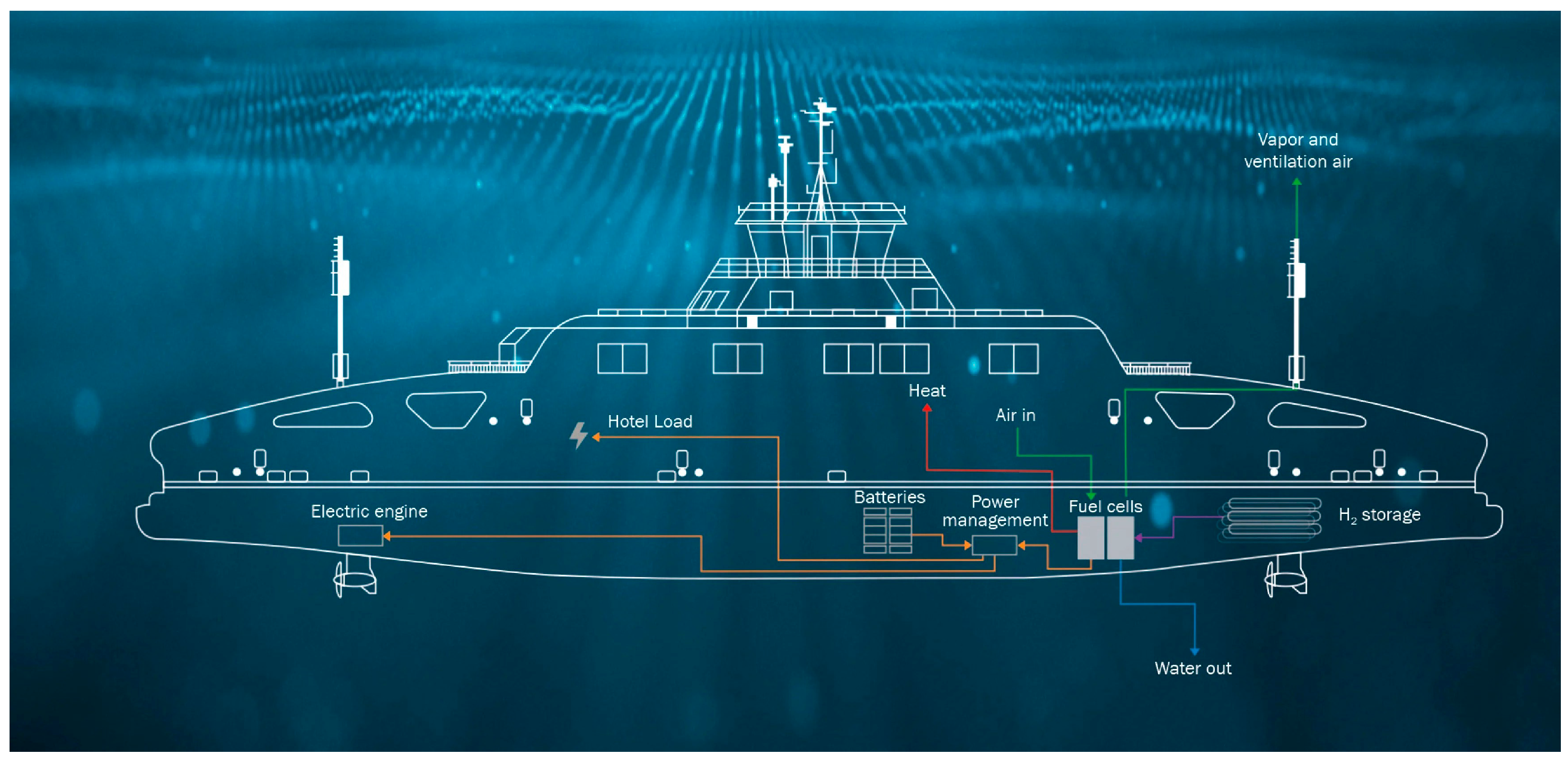
Hydrogen is becoming increasingly important in the shipping sector, and there is a significant increase in interest in hydrogen technologies. However, the implementation of this new technology is still at an early stage, and the current fleet of hydrogen-powered ships is relatively small, literally a few small vessels, with most projects in the demonstration or development phase. As shown in Figure 1, there are currently 10 hydrogen-powered ships on order. It has been eight years since the first small (only 14 m in length) ship powered by this innovative fuel was built. It was in Belgium in 2017 that a prototype of the Hydroville inland passenger catamaran was built in a demonstration version powered by hydrogen-fuelled internal combustion engines with a total power of 441 kW [7]. The year 2021 marked a breakthrough for Norway, where the first larger (82.4 m in length overall) hydrogen-powered passenger and car ferry, MF Hydra, was built. The ferry’s energy system (Figure 2) is equipped with the following components [8,9]:
  • 2 Ballard FCwave™ (Ballard Power Systems Europe A/S, Hobro, Denmark) hydrogen fuel cells (power 200 kW each);
  • Cryogenic tanks from Linde Engineering (Pullach, Germany) (volume 80 m3);
  • Electricity storage in the form of batteries (1.36 ÷ 1.5 MWh);
  • 2 Scania DI16 75M generators (Scania AB, Södertälje, Sweden) powered by hydrogen and diesel oil (power 500 kW each);
  • 2 Schottel SRE 340 LFP thrusters (SCHOTTEL Industries GmbH, Spay/Rhein, Germany).
Norway is a leader in hydrogen strategy, and the MF Hydra ferry project is part of the process of decarbonising Norwegian fjords and confirms the practicality of hydrogen as a clean fuel for short-range shipping.
In the group of offshore vessels, the first Offshore Support Vessel (OSV) with hydrogen fuel cells was the Coastal Liberty (length overall: 42.75 m), which after a refit has been in service in the Wadden Sea since 2024 [11,12]. The ship has been certified by the DNV for its hydrogen-electric system, designed by eCap Marine (Winsen/Luhe, Germany). The system consists of two Ballard FCwave™ fuel cells, 200 kW each, an energy storage system from Lehmann Marine GmbH (Seevetal-Hittfeld, Germany) and three replaceable, high-pressure, containerised hydrogen tanks that do not require refuelling like conventional fuel tanks [13]. It is the world’s first ship powered by green hydrogen. The hydrogen is produced locally from an electrolyser powered by electricity from a wind farm at a local terminal in the port of Cuxhaven. The ship is a pioneering hydrogen-powered vessel and sets a benchmark for the green transition of future ships in this offshore group. The authors assess that this innovative solution is extremely interesting and very practical, promising for future developments.
Two innovative designs stand out among offshore vessels. One of them is Viking Energy (length overall: 94.9 m, cargo deck area 1030 m2), the world’s first LNG-powered Platform Supply Vessel (PSV) [14]. As part of the Norwegian ShipFC project, it was planned to be equipped with ammonia-powered Solid Oxide Fuel Cell (SOFC) (with a total power of 2 MW) and batteries, but the project was suspended due to difficulties in meeting the requirements for such high power with the available cells [15]. The second project is the Ulstein SX190 (length overall 99.0 m, cargo deck area 1000 ÷ 1200 m2), which is Ulstein’s first zero-emission Construction Support Vessel (CSV) powered by hydrogen [16]. It is equipped with Nedstack Proton Exchange Membrane Fuel Cell (PEMFC) (Arnhem, The Netherlands) with a total power of 7.5 MW, of which 2 MW (4 × (5 × 100) kW) is generated by a fuel cell power supply system and 5.5 MW (2 × 2000 kW and 1 × 1500 kW) by MDO-powered internal combustion engines [17]. The vessel can operate for up to four days in zero-emission mode and, according to the manufacturer, in the future, as a result of significant developments in hydrogen storage and fuel cell technology, for up to two weeks [18].
Taking into account the presented data, green hydrogen, recognised as a 100% clean solution, is the subject of the authors’ research on its use in the energy system of a service vessel (SOV), the description and parameters of which are presented in [19].
Some of the technical and economic challenges of using hydrogen as a fuel on ships include:
  • Transport and storage of this fuel, which can be transported in gaseous form (compressed hydrogen CH2) in special high-pressure tanks at 700 bar, or in liquid form (liquefied hydrogen LH2) in special tanks at very low temperatures of around −253 °C;
  • The use of this fuel in ship propulsion systems, i.e., through direct combustion in internal combustion engines or using hydrogen fuel cells;
  • Development of port infrastructure, which is largely lacking worldwide.
An overview of currently conducted research programmes shows that many studies are attempting to assess the feasibility of using hydrogen fuel cells in ship propulsion systems, but there are few studies assessing the space required for hydrogen storage on ships [20,21,22]. For this reason, the authors have attempted to estimate the hydrogen storage space required on SOVs where hydrogen fuel cells are used in the ship’s energy system, similar to the publication [19] with regard to the use of internal combustion engines in this system.
In a previous study [19], the focus was on internal combustion engines powered by various fuels, i.e., diesel oil, LNG, methanol and compressed hydrogen (CH2), for SOV propulsion. The present work extends this research to include:
  • A comparative analysis of SOV power systems using hydrogen-powered internal combustion engines and hydrogen fuel cells (PEMFCs), with respect to space requirements, mass of the power devices and fuel consumption;
  • Evaluation of hydrogen storage methods, including a comparative assessment of liquid hydrogen (LH2) versus compressed hydrogen (CH2), entailing a detailed review of technological challenges and available specialised storage solutions;
  • Benchmarking of the results against the reference fuel, marine diesel oil (MDO);
  • Assessment of the current regulatory framework and standards for hydrogen, together with an analysis of up-to-date market data, including price variability and projected trends.
The introduction of hydrogen fuel cells and cryogenic hydrogen necessitated a comprehensive investigation, encompassing technical aspects, storage safety, and integration with the SOV hull. Thus, the present study goes beyond the scope of the previous publication [19] and provides a qualitatively new contribution to the discourse on maritime decarbonization.

1.2. Hydrogen Transport and Storage—Compressed vs. Cryogenic

1.2.1. Hydrogen—Properties and Energy Significance

The interest in hydrogen as a marine fuel stems from its high mass energy, which is the highest of all fuels. However, its low density under ambient conditions results in low volumetric energy, which requires advanced storage methods to increase its potential [23]. Hydrogen is environmentally friendly because it does not produce CO2 during combustion, only water vapour, and has a calorific value three times higher than diesel fuel (Table 1). It can be produced by using renewable energy sources, i.e., through the electrolysis of water, making it an unrivalled zero-emission fuel in the era of sustainable development.
From the physical point of view, hydrogen can be stored in gaseous or liquid form (Figure 3), both of which pose significant engineering challenges in terms of materials, design, strength and economics. In this study, the authors restrict the comparison to selected, most effective tank solutions available on the market for transporting hydrogen as a marine fuel in both liquid and gaseous state. The characteristics of hydrogen and its classification according to origin have been omitted as they are widely described in the literature [24,25,26,27].
Table 1 presents the basic properties of hydrogen for different forms of storage in comparison with the basic marine fuel MDO.
Table 1. Properties of hydrogen—liquefied and gaseous form compared to conventional fuel [26,27].
No.PropertyCompressed
Hydrogen
(300 bar, 20 °C)
Compressed
Hydrogen
(700 bar, 20 °C)
Liquid Hydrogen
(LH2) (−253 °C)
MDO
(40 ÷ 50 °C)
1.Physical conditionGasGasCryogenic LiquidLiquid
2.Density24 kg/m342 kg/m370.8 kg/m3875 kg/m3
3.Volumetric energy density1.3 kWh/L2.4 kWh/L2.36 kWh/L35 ÷ 38 MJ/l
4.Lower heating value (LHV)120 MJ/kg42 ÷ 43 MJ/kg
5.High heating value (HHV)141.8 MJ/kg45 MJ/kg
6.Flash-point~585 °C>60 ÷ 80 °C
7.Evaporation (boil-off)NoNo0.2 ÷ 1%/per dayVery low
Unfortunately, the low volumetric energy density of hydrogen (in all its forms) requires the use of either large pressure tanks or liquefaction, which is a highly energy-intensive and costly process. Compared to natural gas, hydrogen has three times lower energy content in the same volume. It is also prone to leaks and can easily ignite (wide flammability range) or explode in the presence of ignition sources [28,29]. The level of risk involved in transporting hydrogen at very high pressures and very low temperatures is significant. According to the authors [30], this risk poses serious challenges to the safety of ships using hydrogen as fuel. It is therefore essential that the ongoing process of developing and supplementing international and class regulations governing the safe storage and transport of hydrogen on seagoing ships is finally completed. This is all the more important as this type of fuel has increasing potential for use, among other things, in PEM fuel cells used on a ship sailing between Gothenburg and Kiel [31]. As a result of the analyses carried out, the authors confirmed a high degree of greenhouse gas reduction when using hydrogen, including methanol and ammonia, referring to their entire life cycle, which is invaluable for environmental protection and ongoing climate change [32,33].
It should be noted that hydrogen as a marine fuel is still not fully regulated under the International Code of Safety for Ships Using Gases or Other Low-flashpoint Fuels (IGF Code). Work on this matter is ongoing. In September 2024, during the 10th session of the IMO Sub-Committee on Carriage of Cargoes and Containers (CCC 10), provisional guidelines were agreed upon concerning the safety of ships using hydrogen as a propulsion fuel, covering both functional requirements and general design principles [34]. A complete framework will require further development, with finalisation planned for 2025. Currently, hydrogen-powered ships must undergo the Alternative Design Approval (ADA) process, which requires demonstrating safety equivalence to conventional vessels. Such approval is granted based on individual risk assessments [35]. Full regulation of hydrogen as a marine fuel under the IGF Code is now expected no earlier than 2028 [36].

1.2.2. Hydrogen Transport—Compressed vs. Cryogenic

The publication in 2024, which serves as an introduction to further research [19], characterised the properties of hydrogen, mainly in gaseous form. A preliminary analysis was conducted on the use of hydrogen stored in high-pressure cylinders on offshore vessels, which is recommended for coastal vessels with an autonomy of approximately 14 days. This study also includes a comparative analysis of cryogenic hydrogen in terms of the volume it occupies in the SOV hull, as illustrated in Table 2 by comparing the properties of CH2 and LH2.
From an environmental point of view, the preparation for transport and the transport of compressed hydrogen itself consume less energy (in the range of 6 ÷ 25% for a pressure range of 250 ÷ 700 bar), as the preparation of liquefied hydrogen requires approximately 21 ÷ 30% of the total energy contained in the fuel [19]. To be kept in the liquid form, liquefied hydrogen requires a complex cooling system, increasing energy consumption by several per cent of the total energy contained in the fuel.
According to available literature sources, both types of hydrogen storage systems are crucial for the future of this gas as a marine fuel, with liquefied hydrogen being more efficient for long-distance shipping and compressed hydrogen offering greater flexibility for smaller, short-sea shipping vessels. Gaseous hydrogen may be most competitive in coastal markets, in interregional areas where pipeline construction is technically difficult or economically unjustified [19].
Hydrogen stored at low temperatures or under high pressure poses safety risks related to tank placement within the hull, management of evaporated gases and fire prevention, requiring new approaches to hermetic sealing, ship design and crew preparedness. As noted in Section 1, current regulations are based on provisional guidelines and now require compliance with the IGF Code (SOLAS) [37] and, for hydrogen fuel cells, MSC.1/Circ.1647 [38]. Classification societies such as DNV (Det Norske Veritas), BV (Bureau Veritas), and ABS (American Bureau of Shipping) have their own standards, which can support the approval process for hydrogen systems. The topic of cryogenic system safety is highly significant, yet extensive and demanding. Therefore, this article focuses solely on highlighting the most critical issues, including boil-off gas (BOG), the design of cryogenic tanks and material standards, a brief overview of which is presented in Table 3.
Among global manufacturers of hydrogen transport tanks, only a few offer products for the marine market. Currently, the main players in the global market of specialised tank manufacturers, with extensive experience including the maritime industry, are as follows:
  • For CH2—Hexagon Purus Maritime (Oslo/Langevåg, Norway), NPROXX (Heerlen, The Netherlands), Luxfer Gas Cylinders (Riverside, CA, USA), Steelhead Composites (Golden, CO, USA), Hyfindr (Stuttgart, Germany), MAHYTEC (Dole, France);
  • For LH2—MAN Cryo (Göteborg, Sweden; Augsburg, Germany), Chart Industries (Ball Ground, GA, USA), Linde Engineering (Pullach, Germany).
Table 4 presents the general characteristics of tanks for compressed and liquified hydrogen (CH2 and LH2).
The full characteristics of the tanks used in the study, together with their technical specifications, are presented in the next section of the article in the form of design assumptions. At present, these are tanks with the highest hydrogen volume utilisation ratio in relation to the tank’s own weight.

1.3. Hydrogen Fuel Cells in Ship Propulsion

The use of hydrogen in shipping can significantly reduce carbon dioxide emissions to the atmosphere, and ship energy systems using fuel cells powered by hydrogen, among other things, have significant potential to meet the decarbonisation targets set by the IMO [21,51,52,53,54]. Currently, ship energy systems, i.e., those used to generate propulsion power and electricity, are still dominated by internal combustion engines, which are adapted to burn both typical hydrocarbon fossil fuels and alternative fuels, including methanol, ammonia and hydrogen. This is slowly changing, as more and more projects are emerging that use fuel cell technology, which could become competitive with internal combustion engines if it achieves low total costs, low recycling costs and high efficiency over a wide range of power outputs.
The types, applications and operating parameters of fuel cells have been described in numerous publications, with a very comprehensive overview provided in [55], which compares fuel cell systems suitable for marine applications. In particular, it discusses two types of fuel cell technologies, namely PEMFC and SOFC, widely used in the marine industry compared to other types of cells (MCFC, PAFC and AFC). Table 5 summarises the main fuel cell technologies and their general characteristics.
One important feature of fuel cells is the relatively low power of a single module (from one to three-figure power in kW), which for marine propulsion can be seen as a disadvantage, as ships usually require power output of four to five-figure kilowatts. However, fuel cells have a modular design, so that several cells can be combined into a single system with a sufficiently high power output to meet the requirements of a ship’s energy system, as demonstrated by the offshore energy systems of Viking Energy [15] and Ulstein SX190 [17].
Of the currently available fuel cells of the PEMFC and SOFC types and for marine applications with a power output of over 100 kW, Table 6 presents specifications of selected cells.
Some of the fuel cells listed in Table 6 will be used for the research, but in order to cover the electricity demand in various operating conditions of SOVs, it will be necessary to combine several cells into a system with a sufficiently high power output, adapted to the demand of the ship’s energy system. Single cells currently available have a power output of 200/300 kW (Table 6), and in the case of PEMFCs and SOFCs, which are widely used in the marine industry, the maximum power output of a cell system is approximately 1000 kW (Table 5). Therefore, three or four fuel cell systems will be required to cover the power demand of the SOV under consideration.
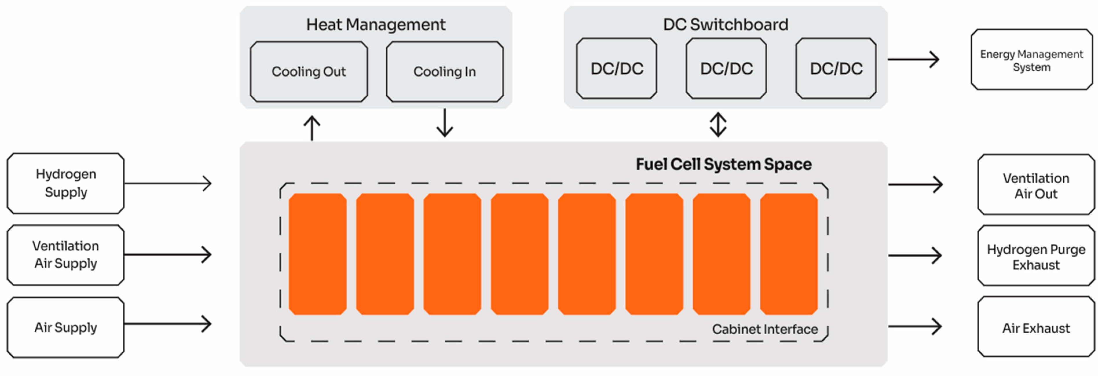
An example of fuel cell system application and the general design of the entire system is shown in Figure 4, while Figure 5 contains examples of the power and efficiency characteristics of fuel cells.
It follows from the given characteristics of fuel cells (Figure 5) that their efficiency is load-dependent, with the highest values being achieved at low loads.
Another significant aspect concerns the energy management system (EMS), which is discussed in a noteworthy manner in the paper [63], particularly with regard to monitoring fuel cell operating temperature and its influence on their durability and efficiency. Such a system facilitates the optimisation of energy consumption, regulation of the thermal state of energy-source systems and maintenance of appropriate indoor environmental parameters (e.g., through heat recovery), which contribute to fuel savings, enhanced durability of energy-source components and reduced operational costs.
Polish scientists are also involved in research on fuel cell technologies. HydrogenTech Sp. z o.o. (Krakow, Poland) has developed a technology for double-sided SOFCs that increases their active surface area, resulting in higher power output with smaller dimensions. These cells enable the creation of clusters in a small power range, i.e., clusters up to 100 W for laboratory research or kilowatt clusters for industrial applications [64]. The Łukasiewicz Research Network in Warsaw (Poland) is conducting research on low-temperature PEMFC fuel cells powered by hydrogen [65].
In addition to the typical use of fuel cells in ship energy systems, there are also various types of hybrid drives that additionally utilise battery systems and traditional internal combustion engines. Interesting research was conducted in [66], where the concept of 3 variants of the energy system of the research vessel “Robert Gordon Sproul” was compared, i.e., a traditional propulsion system (diesel-electric) and 2 hybrid systems (hybrid battery/diesel-electric and hydrogen fuel cell/diesel-electric). The results of these studies showed that the superior performance of the hydrogen fuel cell/diesel-electric system is attributable to the higher volumetric energy storage density of the LH2/fuel cell combination. The authors of another study [67] also point out that integrating energy storage with ship propulsion systems using fuel cells allows for the creation of hybrid power systems that reduce the frequency of fuel cell start-up and stop cycles and reduce the energy load on individual fuel cell stacks. Global research is therefore moving in several directions, related on the one hand to hydrogen combustion in internal combustion engines and the development of fuel cells, and on the other to the hybridization of ship energy systems [68,69,70,71] or the development of energy management systems [63]; however, such issues may constitute a contribution to further research.

1.4. Research Aim

As a result of a literature review, the aim of the research herein presented is to verify the possibility of using a fully hydrogen-powered SOV energy system.
Achieving this goal requires an analysis of the design of a hydrogen storage system for two forms of hydrogen, i.e., gaseous (compressed CH2) and liquid (liquefied LH2), on a small SOV using hydrogen fuel cells for propulsion. For comparison, hydrogen-powered internal combustion engines will be considered, while meeting operational expectations concerning efficiency related to cruising range, tank space and the entire hydrogen propulsion system.
The study is based on the existing SOV design concept and its operational profile, i.e., the sequence of operating states typical for servicing offshore wind farms. The power demand diagram for individual operating modes, described in detail in [19,72], formed the basis for further analysis.
To achieve the main research objective, i.e., to assess the feasibility of using hydrogen as an innovative, zero-emission marine fuel in fuel cells on SOVs, the following analytical steps were carried out:
  • Physical and chemical properties of hydrogen: compressed hydrogen (CH2) and liquefied hydrogen (LH2) were compared in terms of energy density, storage conditions, safety and technological requirements under marine operating conditions on SOVs;
  • Selection of power supply technology: available technologies, i.e., PEMFC, SOFC and hydrogen-powered internal combustion engines, were analysed in terms of technical parameters and suitability for the SOV power profile, and possible configurations and their arrangement in the hull were proposed;
  • Fuel consumption and storage systems: fuel consumption was estimated for selected operating variants, a suitable tank system for LH2 was selected and compared with CH2, LH2 fuel tanks were laid out on the SOV’s working deck and their impact on the ship’s overall space was assessed;
  • Space efficiency: the degree of hull space utilisation was assessed in terms of the volume required for hydrogen storage, indicating the design implications;
  • Simplified economic analysis: a preliminary analysis of the costs of using hydrogen as a marine fuel was carried out; due to the limited availability of data (e.g., price of green hydrogen, bunkering infrastructure, component costs), the results are approximate.

2. Initial Assumption and Methodology

2.1. Specifications of the SOV

This specific study analysed the use of hydrogen on an SOV intended to operate in the operational area of wind farms in the Baltic Sea (Baltica 1), located approximately 80 km from the coastline. The analysis is based on average weather conditions for this area during the operation of a vessel equipped with a DP2 system and a crew of 60. Here are the ship’s main particulars [19]:
  • Length between perpendiculars, Lbp = 72.0 m;
  • Breadth, B = 18.0 m;
  • Hull depth, H = 8.9 m;
  • Displacement, D = 5004 t;
  • Deadweight, DWT = 1005 t;
  • Cargo weather deck area, Awd = 620 m2.
The assumed autonomy of the vessel is max. TS = 14 days, and the annual operating period TR = 250 days.
Based on the analysis of SOV energy system solutions contained in the database of similar ships developed by the authors, as discussed in detail in [19], the most commonly used diesel-electric propulsion system was adopted for the study in the following configuration:
  • Total power of the energy system, NC = 5400 kW;
  • Power of the generator (3 pcs.), NAP = 1800 kW;
  • Main propulsion power, NNG = 2800 kW;
  • Power of the main azimuth thruster (2 pcs.), Np = 1400 kW;
  • Bow tunnel thruster power (2 pcs.), NSS = 1200 kW;
  • Bow retractable azimuth thruster power (1 pcs.), NSW = 800 kW.
In previous studies [19], four variants of internal combustion engines were powered by different types of fuel, i.e., diesel oil, LNG, methanol and hydrogen, which allowed for a design analysis of the ship in terms of estimating the space occupied in the ship’s engine room, estimating the volume and mass of fuel tanks depending on the type of fuel, and estimating the volume occupied in the ship’s hull space.
The same ship and type of energy system were used in the study, with only the engines being replaced with hydrogen fuel cells. Of the fuel cells currently available (Table 5) with a power output of over 100 kW, three solutions were selected for analysis, which, in the authors’ opinion, are best suited for use on SOVs, i.e.,
  • Ballard’s Power System (Hobro, Denmark)—FCwave™ module;
  • Corvus Pelican System (Nesttun, Norway)—Corvus Pelican (FCS) system;
  • PowerCell Marine System (Gothenburg, Sweden)—Marine System 225 module.
A comparison of three variants of hydrogen fuel cell systems and two systems with hydrogen-powered internal combustion engines (presented in [19]) allows for a design analysis of the ship in terms of the estimated volume and mass of hydrogen tanks and the space occupied in the SOV hull. Thus, the analysis will allow for the appropriate spatial layout of the ship’s energy system (hydrogen fuel cells and fuel tanks), taking into account the location of the engine room, and for the assessment of the impact of a given variant on the space occupied, displacement or load capacity of the ship, compared to an energy system with internal combustion engines.

2.2. Hydrogen Storage and Transport on SOV

As a result of a literature review, market analysis and current technological possibilities in hydrogen transport by sea, the authors decided to use the following tanks in two variants in the project:
1.
A tank in the form of a type IV high-pressure composite cylinder, manufactured by Hexagon Purus, pressure 700 bar at ambient temperature; modular installation of the cylinder with a frame guard on a service vessel.
Technical data—H2-70-705X2078 [73]:
  • Outside diameter, DCH2 = 705 mm;
  • Overall length, LCH2 = 2078 mm;
  • Cylinder weight, WCH2 = 264 kg;
  • Volume, V = 457 L;
  • Hydrogen capacity, VCH2 = 18.4 kg;
  • Weight of the hydrogen cylinders, WC+CH2 = 282.4 t;
  • Rack weight for 9 pcs CH2 cylinders, WRack CH2 = 238 t acc. [19].
2.
LH2 cryogenic tank—ISO (HYLICS) in a 40 ft stainless steel frame with container dimensions (12.19 m × 2.44 m × 2.59 m), manufactured by Linde Engineering, operating pressure 12.75 bar at a temperature of −253 °C; the tank has vacuum-perlite insulation, optionally with LIN-Shield (liquid nitrogen shield), low boil-off evaporation losses (<0.5%/day).
  • Technical data [50]:
    • Outside diameter, DLH2 = approx. 2200 mm;
    • Overall length, LLH2 = approx. 10,500 mm;
    • Usable tank capacity (gross), V = 48.4 m3;
    • Weight of liquid hydrogen (LH2 charge), WLH2 = approx. 3040 kg,
  • (at 10% loss—for hydrogen density ~70 kg/m3);
    • Cryogenic tank weight LH2, WZ = approx. 12,500 kg,
  • (fittings, valves, insulation);
    • Weight of the steel frame ISO 40 ft, WR = approx. 3000 kg;
    • Weight of the tank with frame, WZR = approx. 15,500 kg;
    • Total weight (tank, frame and hydrogen), WC = approx. 18,500 kg.
Each transport variant has a structural element in the form of a frame for the module (3 × 3) with 9 pressure cylinders and a container frame for the cryogenic tank. Each system will be transported on the open main deck.
The selection of the number of cylinders/tanks with the appropriate structural frame will be carried out later in this article, based on an analysis of the required hydrogen supply, taking into account its mass and the volume necessary to ensure the operational autonomy of the SOV.

2.3. Operational Profile of Service Vessel Work

The specific nature of SOV operation consists of several stages, and the entire cycle of its operation is referred to as a mission, with one mission consisting of four stages [19]:
  • Normal operation: shipping to the working area.
  • Service Work in the offshore wind farms in the Baltic Sea.
  • Normal operation: shipping to port.
  • Stopover in port.
The study assumes the most common mission duration, i.e., a maximum of 14 days, and the possibilities of storing the appropriate amount of hydrogen on board the SOV will be analysed for this period.
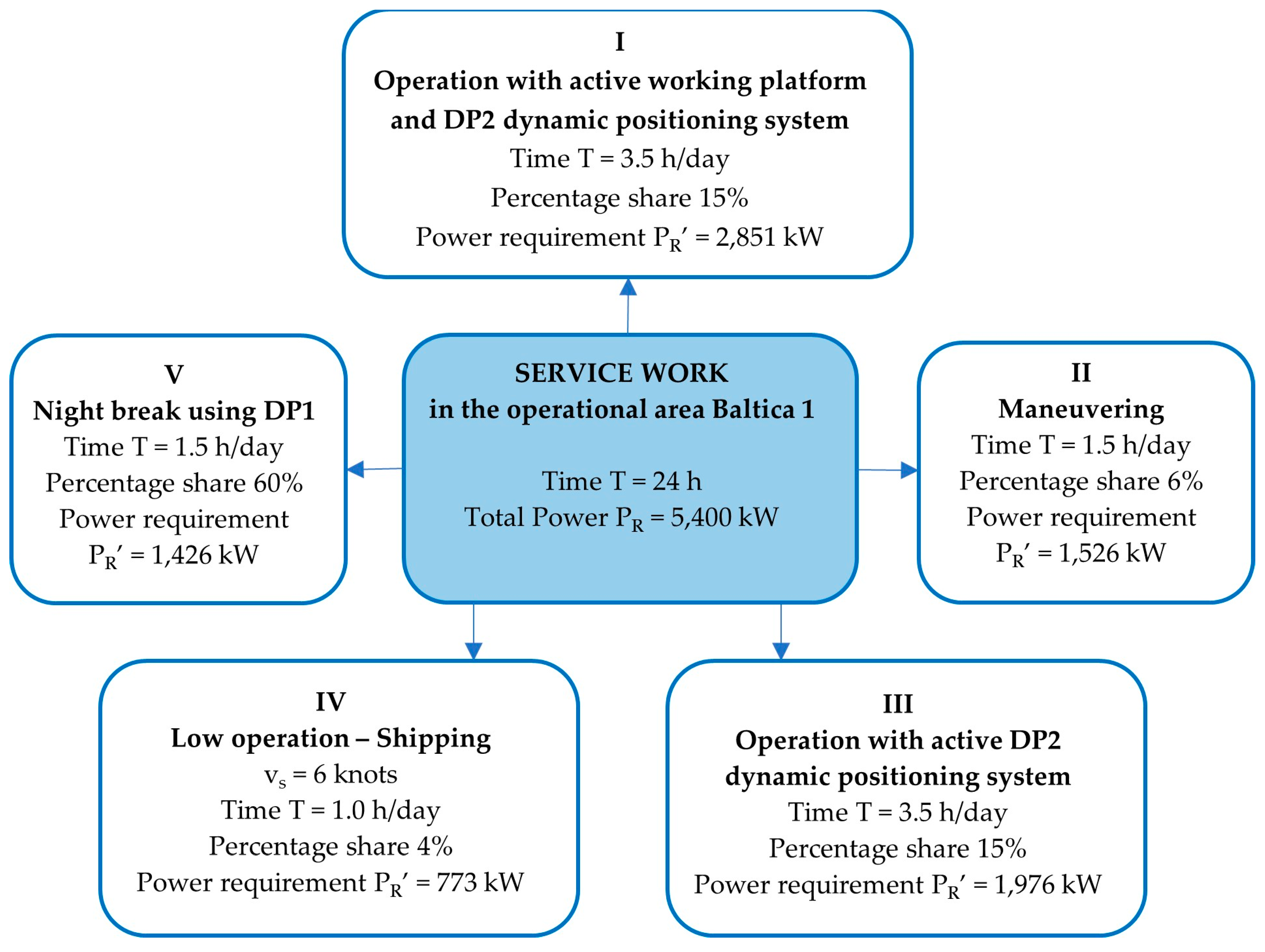
Of all the stages of the mission, the main tasks of the vessel are, of course, stage 2, i.e., service work around offshore wind farms, and for this stage of the vessel’s operation, a division into five operating states, marked from I to V, was adopted. The operating states of the analysed service vessel have been discussed in [19,72], but for the sake of clarity, Figure 6 shows a diagram of the SOV’s service work divided into individual operating states with their duration and energy requirements.
As can be seen in Figure 6, the individual operating states of the SOV during service operations are characterised by different durations during the day and different power requirements, which will be taken into account in the analyses.

2.4. Research Method

The use of hydrogen as a new fuel for service vessels requires an analysis of its impact on the vessel design, with particular emphasis on safety aspects and the space requirements of storage systems for this demanding fuel and environmentally friendly propulsion systems. A feasibility assessment can be carried out using analytical methods and CAD tools (AutoCAD Mechanical 2025) to support the modelling and integration of design solutions.
The article uses a computational method to assess the feasibility of using hydrogen as a fuel for a service vessel. The analysis covers aspects of hydrogen storage and transport, as well as the ability of the propulsion system (assuming fuel cells versus internal combustion engines) to meet power demand under variable loads during service operations in offshore wind farms. The assessment was based on SOV technical and operational data, IMO guidelines on hydrogen, available propulsion technologies (hydrogen fuel cells and hydrogen-powered internal combustion engines) and high-pressure and cryogenic hydrogen storage systems.
As part of the research, not only were 2D technical drawings developed, but also three-dimensional models of cylindrical tanks (for CH2 and LH2) and a mounting frame using Autodesk Inventor Professional 2025 and AutoCAD Mechanical 2025 software. The models (based on actual tanks available on the market) took into account the geometric parameters, weight, surface area and volume occupied by the storage system, which enabled precise spatial and structural analysis. The advantage of using CAD software was the ability to visualise the designed elements, check the compatibility of the modules with the ship’s structure and evaluate the arrangement of tanks and propulsion systems in the SOV hull.
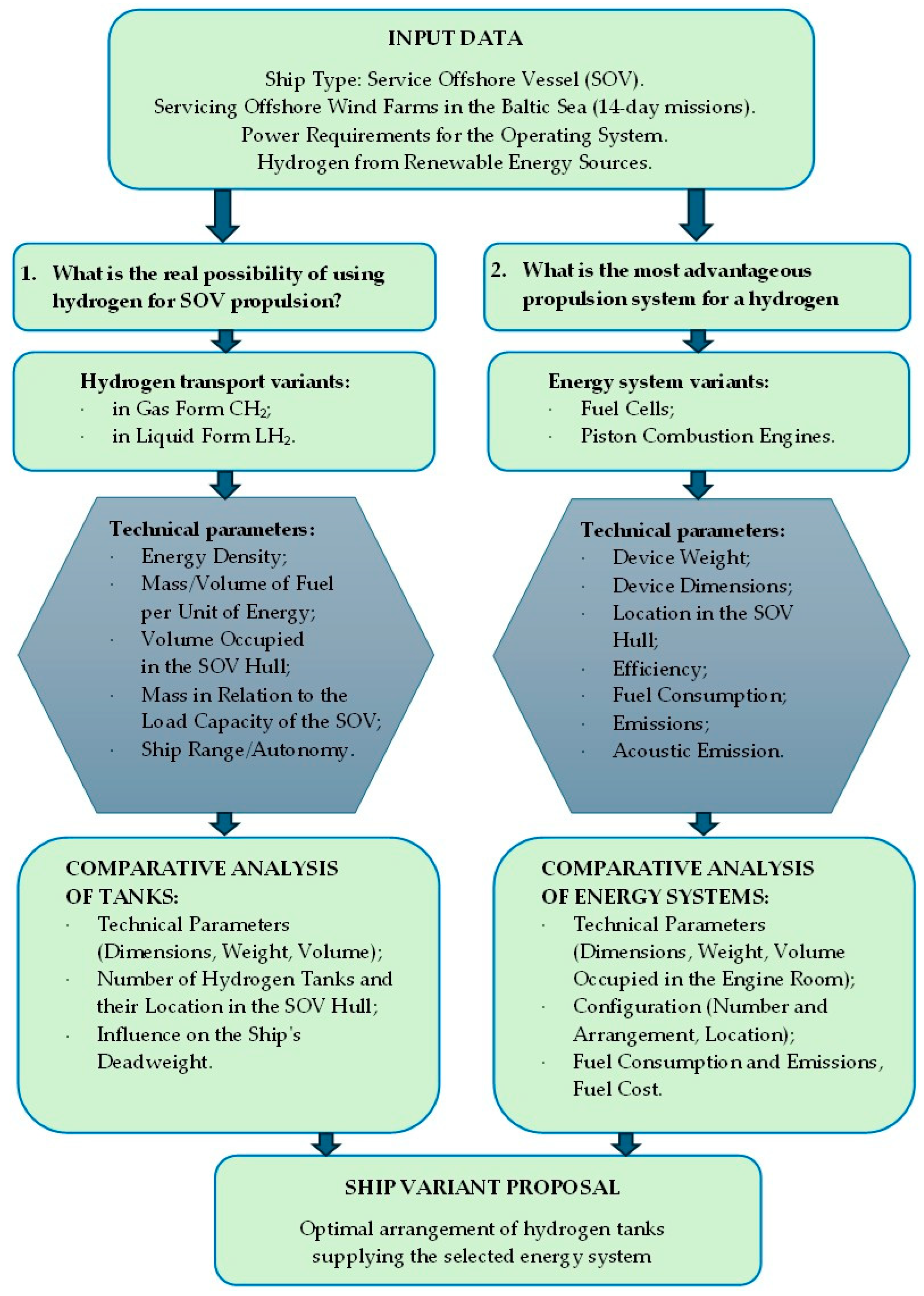
Figure 7 presents the methodology of the main stages of computational analyses resulting from the design assumptions and research context.
The analysis took into account the differences between storing hydrogen in compressed and liquefied form (Table 2Section 1.2.2), which significantly affect the costs and method of storage. Liquefied hydrogen takes up less space but requires very low temperatures, while compressed hydrogen requires more space but has a simpler infrastructure. Similarly, propulsion systems have been compared—fuel cells are slightly more efficient than hydrogen-powered internal combustion engines, but they have higher requirements in terms of fuel purity and cooling systems. Their advantage, however, is that they do not produce exhaust emissions and are quieter, which is a point in their favour.

3. Analysis of the SOV Design for the Use of Hydrogen Fuel Cells

Based on SOV data (Section 2), the weight, volume and space occupied by tanks of a fuel cell energy system were estimated and compared with the results obtained for internal combustion engines given in [19].

3.1. SOV Energy System Specification

3.1.1. Selection of the Hydrogen Fuel Cells

In the previous work [19], an SOV energy system was selected based on a database of similar ships (Section 2). In the present study, hydrogen fuel cells were used instead of hydrogen-powered internal combustion engines. Among the available solutions with a power output of over 100 kW for marine applications, the authors have identified three that are best suited to SOVs:
  • Ballard’s Power System (Hobro, Denmark)—the FCwave™ module designed to provide emission-free energy for marine vessels, which is the world’s first fuel cell approved by DNV for marine applications. The system is scalable from 200 kW to 1.2 MW to match a wide range of power requirements for vessels operating on short or long, more demanding routes [56].
  • Corvus Pelican System (Nesttun, Norway)—the Corvus Pelican fuel cell system (FCS) can serve as the primary or auxiliary power source in vessels. This system is ideal for zero-emission operation for coastal vessels and offshore vessels operating over short distances, as well as vessels that operate on routes where hydrogen fuel is available. The system is scalable from 340 kW to 10 MW [57].
  • PowerCell Marine System (Gothenburg, Sweden)—the Marine System 225 module is a compact fuel cell system that is highly efficient and easy to install and maintain. The system allows power scaling from 225 kW to megawatt outputs. It is also flexible in terms of fuel use and can run on reformed renewable fuels [58].
Table 7 presents the specifications of the selected fuel cells.
The data compiled in Table 7 show that in terms of dimensions and weight, the FCwave™ and Marine System 225 are similar, as they have similar energy density in relation to weight and volume, with the Marine System 225 being approximately 8% heavier. With the same power, it would occupy approximately 2% less space. The Corvus Pelican Fuel Cell System performs the least favourably, as it has more than twice the weight and occupies twice the space of the other systems with the same power.
For further comparative analysis, Ballard fuel cells were selected due to their lowest weight, and Corvus fuel cells due to their highest power and the possibility of using the smallest number of modules in the system.

3.1.2. Comparison of Internal Combustion Engines and Fuel Cells

According to the declarations of hydrogen fuel cell manufacturers, summarised in Table 7, the cells can be arranged into units, allowing power to be scaled up to 10 MW, which ensures that the electricity demand of the analysed SOV can be met in various operating conditions. With the assumed power demand of 5400 kW, it will therefore be necessary to use 3 or 4 cell systems in order to optimise the use of space in the power plant (similar to the authors’ previous work [19] using 3 internal combustion engines in the SOV energy system). Taking into account the specific nature of SOV operation and the variable electricity demand in its various operating states (Figure 3), it seems important to arrange the cell systems in such a way that they optimally supply electricity of the appropriate power in each operating state of the SOV. An example diagram of an energy system with three Corvus Pelican hydrogen fuel cell units is shown in Figure 8.
The Corvus Pelican hydrogen fuel cell system shown in Figure 8, with a single module power of 340 kW, consists of three units in the following configuration:
  • 2 × 1700 kW (5 × 340 kW);
  • 1 × 2040 kW (6 × 340 kW).
Therefore, the entire system has a total power of 5440 kW, satisfying the assumed power demand of the SOV, and consists of 16 modules. Because the individual units can be controlled independently, the proposed system will optimally cover the power demand in various operating conditions of the SOV.
The energy system so configured, with three hydrogen fuel cell units, corresponds to the energy system analysed in the authors’ previous work [19], combining three internal combustion engines. This allows a direct comparison of both energy systems in terms of the space occupied in the engine room and the distribution of masses, as shown in Table 8.
In addition to the dimensions of the generating sets and fuel cells themselves, the space required for all accessories and maintenance (specified by regulations and manufacturer’s requirements) must also be taken into account, which obviously increases the usable area. Taking into account the width of the ship’s hull B = 18 m, gensets or fuel cell modules can be placed in the engine room next to each other along the ship’s centre line. For the calculations, an approximate service space of 1 m around the machinery and a distance of 1.5 m between two pieces of equipment were assumed. This space guarantees convenient daily operation and provides adequate service space during inspections and overhauls.
For the analysis, the fuel cell units were configured so that their length approximately corresponds to the length of the internal combustion engines, approximately 6.7 m. In the adopted fuel cell configuration, the units have an average length of approximately 7.2 m, so for the same service space for both types of power systems, the space occupied in the engine room is critical. It is greater by 0.5 ÷ 1.0 m when using fuel cell units.
A comparison of internal combustion engines and fuel cells as the main power plants for SOVs (Table 8) shows that:
  • When arranged in rows, the fuel cell modules occupy on average 13.7% (9.3 ÷ 18.5%) more space in the engine room than internal combustion engines. However, fewer fuel cell service devices may contribute to overall reduction in the space required for the entire engine room and easier spatial planning;
  • The fuel cell modules used are significantly lower than internal combustion engines, by an average of 24.3% (18.1 ÷ 29.9%), and do not require as much service space over them as combustion engines, which leads to a more optimal layout of the entire engine room in the SOV hull;
  • The fuel cell modules used are significantly lighter than internal combustion engines, by an average of 50.6% (20.0 ÷ 73.3%), in particular Ballard’s FCwave™ fuel cells (Ballard Power Systems Europe A/S, Hobro, Denmark), which are 64% lighter than the Wärtsilä engine (Wärtsilä Corporation, Helsinki, Finland), 73% lighter than the BEH2YDRO engine (Anglo Belgian Corporation, Gent, Belgium) and 55% lighter than Corvus fuel cells (Corvus Energy, Nesttun, Norway), which will significantly reduce the total weight of the power plant;
  • Fuel cells need fewer installations handling power machinery (no exhaust gas systems, lubrication or start-up systems), which lowers the engine room weight and enables more optimal layout;
  • The use of hydrogen fuel cells reduces atmospheric emissions to zero, but limits the possibility of using other types of fuel;
  • Modular design of fuel cells allows arranging them more optimally and flexibly in the power plant, and power scaling facilitates the selection of cells and their configuration depending on the electricity demand in different operating states of the SOV.
Furthermore, it is also important that fuel cells will result in significantly quieter operation and significantly lower vibrations generated by the SOV’s power system. However, investment costs will be significantly higher, as fuel cells are expensive to produce, as the technology involves expensive materials such as platinum and other rare metals.
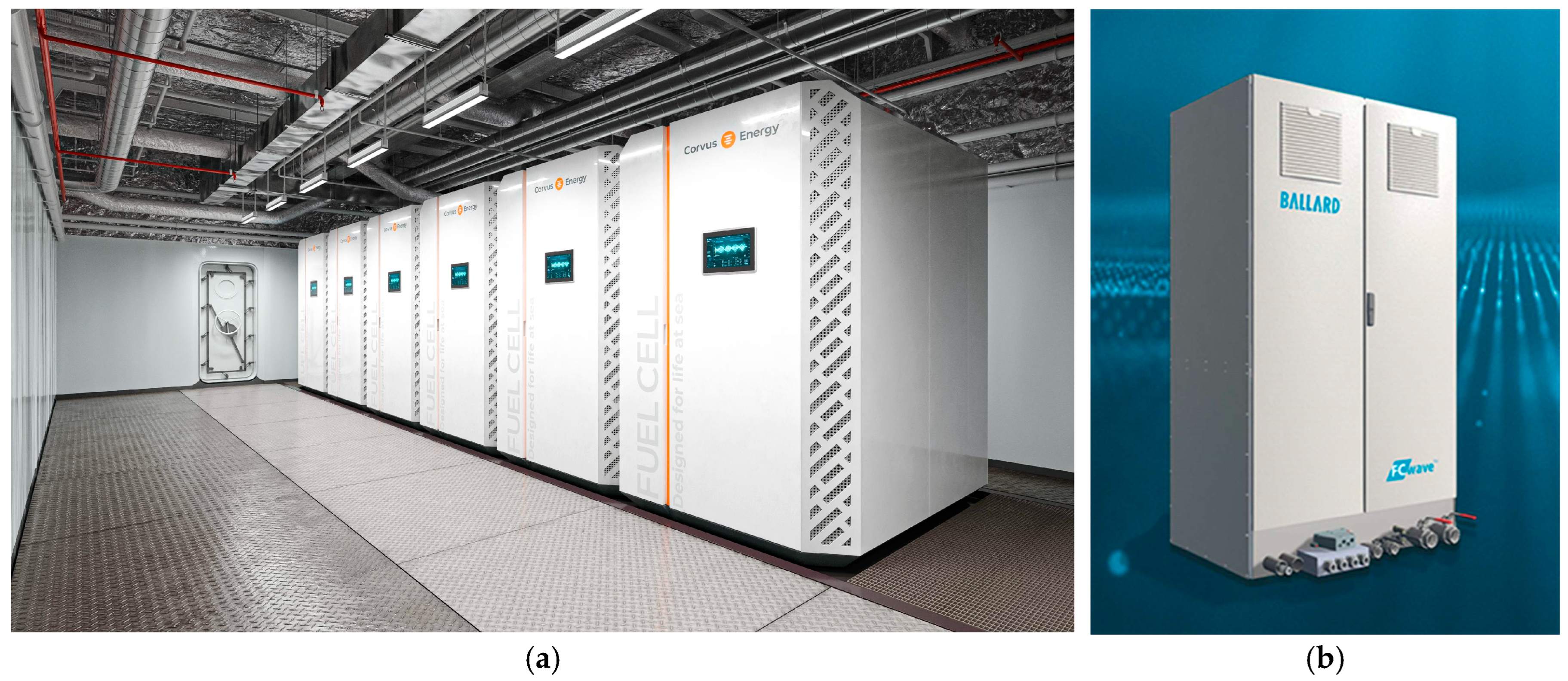
Of the two selected types of fuel cells, Ballard’s Power System appears to be the best solution due to the lowest weight of the entire system, but it requires the use of as many as 27 cell modules with a power of 200 kW each. In contrast, the Corvus Pelican Fuel Cell System requires only 16 cell modules with a power of 340 kW each, but the weight of the entire system is twice as high. From a spatial planning perspective, attention should be paid to the dimensions of the fuel cells themselves, as this determines their proper positioning in relation to each other. Figure 9 shows the layout of six Corvus Pelican fuel cell modules, with a Ballard fuel cell module in the background.
Assuring the safety of the entire process of refuelling, storage and consumption of hydrogen requires the use of a system that prepares the fuel before it is delivered to the fuel cells. However, the process of fuel preparation and delivery is not relevant to this research, so its description has been omitted.

3.2. Analysis of the Hydrogen Supply and the Arrangement of the CH2 and LH2 Tanks in the SOV Hull

3.2.1. Hydrogen Supply—Internal Combustion Engines vs. Fuel Cells

To estimate the required fuel supply for the SOV under consideration, the type of electricity generation equipment used in the energy system was taken into account, i.e.,
1.
For hydrogen-powered internal combustion engines, the overall efficiency estimated in [19] was assumed to be ηDE = 0.44, with an average load of 80% of the rated power.
In addition, the estimated power demand in the assumed SOV operating modes is shown in Figure 6, along with respective duration of each mode.
2.
For hydrogen fuel cells, the maximum overall efficiency specified in the manufacturers’ catalogues was assumed to be ηFC = 0.52 ÷ 0.56, depending on the type of cell (Table 7).
In addition, changes in efficiency and fuel consumption depending on the cell power (graphs in Figure 5) were also taken into account; they show that at maximum fuel cell power, their efficiency drops to around 0.42. For further calculations, the fuel cell efficiency was therefore assumed to be ηFC = 0.46, which corresponds to an average cell load of 80% of the rated power.
The formulas of the authors [19] were used to calculate the required fuel supply, including its volume and the number of tanks. Given the similar efficiencies of internal combustion engines and fuel cells assumed in the calculations, comparable fuel consumption values were obtained. Table 9 presents the results of calculations of the required fuel supply for hydrogen in compressed and liquid form, compared to MDO, a typical marine fuel. MDO consumption refers to internal combustion engines, while hydrogen consumption refers to both types of engines.
The data in Table 9 show that a very large volume of hydrogen is required to power combustion engines and fuel cells, which is more than seven times greater for compressed hydrogen and more than four times greater for liquid hydrogen than the amount of MDO fuel required. At the same time, the mass of hydrogen is only 1/3 of the mass of MDO. Due to the similar efficiency of fuel cells and internal combustion engines, their hourly hydrogen consumption will be similar, and thus the required fuel supply on board will also be similar.
A more detailed summary of the variability of hydrogen demand in compressed (CH2) and cryogenic (LH2) form, together with the corresponding volume and storage area depending on the service time of the ship, is presented in Figure 10, whereas Figure 11 presents a comparative assessment of the deck area utilisation by the LH2 and CH2 tank systems, including their respective percentage distribution.
The following statements can be made based on the comparative analysis (Figure 10 and Figure 11) of LH2 and CH2 hydrogen storage systems on board the SOV, it can be concluded that:
  • Weight of compressed CH2 significantly exceeds the weight of the LH2 system in the entire analysed cruising range, as for 14 days of operation, the weight of the LH2 system (tank with frame) is approx. 244 t, while for CH2 (cylinders with frame) it is as much as 648 t, more than 2.6 times more;
  • Volume of LH2 storage systems is more than three times smaller for 14 days than that for compressed hydrogen (LH2—1002 m3, CH2—3198 m3);
  • The use of deck space for LH2, ranging from 5% to 62%, represents an efficient utilisation, whereas for CH2, ranging from 18% to 248%, the available deck space is fully utilised and exceeded after approximately four days of operation, rendering the solution impractical for continued service beyond this period.
Moreover, it can be said that LH2 cryogenic tank system constitutes over 2.5 times less of the ship’s deadweight than CH2 (24% to 64%), which can significantly affect the ship’s load capacity and stability (which is not shown in the figures above).

3.2.2. Hydrogen Storage on SOV—CH2 vs. LH2

Research by the authors [19] has shown that the weight of the compressed hydrogen CH2 system (648 t) with an SOV load capacity of 1002 t restricts the functionality of the SOV (transport of personnel or spare parts to offshore wind farms), and the storage of hydrogen CH2 for 14 days is technically impossible.
The identified limitations prompted the authors to consider alternative solutions, such as:
  • Shortening the length of service missions;
  • Developing infrastructure for refuelling hydrogen at sea (e.g., through offshore electrolysers powered by wind farms);
  • Integration of energy storage systems in the form of batteries.
In view of the above, this study conducted an extended analysis of the SOV energy system, which uses hydrogen fuel cells as the main source of electricity generation and liquid hydrogen (LH2) storage as the energy medium. For comparison, previous analysis results are presented (Table 10).
The calculations (Table 10) show that the storage of liquid hydrogen (LH2) on an SOV is much more efficient than compressed hydrogen (CH2). For the same autonomy, the LH2 system requires less fuel volume and several times fewer tanks, which reduces the load on the vessel. For example, for 14 days, the number of LH2 tanks is 13, while 2096 CH2 cylinders are required. The use of liquid hydrogen (LH2) may be more effective due to its greater potential for integration with the deck space. The cost of a complex cryogenic system may be a drawback.
This change has made it possible to reduce the weight and volume of the entire fuel system while maintaining the efficiency of converting chemical energy from fuel into electrical energy. Fuel cells with similar efficiency have lower space requirements and lower weight of the entire energy system than internal combustion engines.
In summary, it can be concluded that the combination of liquid hydrogen and fuel cells is an effective and promising alternative to compressed hydrogen and internal combustion engines, improving the efficiency of SOVs in the context of zero-emission maritime transport.

3.3. Fuel Costs

Hydrogen is one of the most expensive fuels, with the price of green hydrogen currently reaching several thousand dollars per tonne. In addition, the costs associated with hydrogen include the prices of high-pressure composite tanks or cryogenic tanks and the system for installing the tanks in the SOV hull. These data are not published and have therefore not been taken into account in the considerations. It should be emphasised, however, that parameters such as system efficiency, evaporation rate, fuel prices and energy distribution exert a considerable influence on the final results of the analyses. Due to the lack of reliable and comprehensive data, as well as the inherent difficulty in estimating fuel price variability, these factors could not be accounted for in the present study at this preliminary stage.
These calculations include an estimate of fuel costs for a 14-day mission, based on current prices for green hydrogen (H2) and, for comparison, conventional MDO fuel, according to rates as of 29 July 2025:
  • PMDO = 510 $/t—unit price of MDO based on [77],
  • PH2 = 7.7 $/kg = 7700 $/t—unit price of green hydrogen based on [78].
Knowing the fuel mass required (Table 9) and the above unit prices, the fuel costs Kfuel for a single ship mission were estimated as follows:
  • Kfuel CH2, 326,942 $;
  • Kfuel LH2, 313,852 $;
  • Kfuel MDO, 59,084 $.
The slight difference in costs between the two forms of hydrogen (LH2 and CH2) results from the minimal difference in the required fuel mass. The same relationships as in [19] were used for the above calculations.
Green hydrogen is currently significantly more expensive than MDO fuel (more than five times more for a single mission), but it has the potential to reduce costs in the future as renewable energy prices fall and production and distribution technologies develop. At present, the unit price of hydrogen is more than 15 times higher than that of MDO, which makes it impossible to consider it a real competitor without financial support. In the last six months, MDO fuel prices have been highly volatile, so the results of the calculations should be treated as indicative.
Taking into account the entire service life (TR = 250 days), the number of service trips was estimated at 17 missions per year. This value has a significant impact on annual fuel consumption costs.

4. Results

4.1. Location of Hydrogen Tanks on the Ship

Given the current limited regulations [19] and the lack of clear guidelines on the possibility of installing hydrogen tanks inside the ship’s hull, LH2 liquid hydrogen tanks were planned exclusively on the SOV’s working deck (significantly reducing the ship’s main working area). Like in the case of hydrogen in high-pressure cylinders, it is not possible to store 13 tanks on the open deck (according to the above calculations (Table 10)) due to deck space requirements. For the SOV under consideration, the possible operating time of the vessel with a cryogenic tank system with the assumed parameters (Section 2.2) is limited to approx. 9 ÷ 10 days. Therefore, to meet the requirement of a 14-day SOV mission, its energy system would need to employ hybrid solutions, e.g., a combination of fuel cells with battery energy storage, as presented in the introduction and conclusions summarising the work.
Figure 12 presents a visualisation of the selected cryogenic tank (40 ft ISO, HYLICS, Linde Engineering), while Figure 13 and Figure 14 depict a hypothetical layout of tanks with stored hydrogen on the SOV deck, representing the most likely and feasible configuration, i.e.,
  • Maximum number of tanks, 8 ÷ 9 for a 9 ÷ 10 day mission;
  • Total fuel reserve MTfuel, 27 ÷ 30 t;
  • Fuel volume Vfuel, 385 ÷ 428 m3;
  • Full tank weight (with hydrogen), 134.3 t;
  • Cryogenic hydrogen tank weight (with hydrogen), 151 ÷ 169.8 t.
The obtained values are acceptable, considering the design parameters of the analysed ship. The weight of the tank system, including the frame, accounts for approximately 15 ÷ 16% of the ship’s deadweight, and the maximum deck area occupied by the tank system is roughly 38 ÷ 43% of the total working deck area (620 m2).
From the perspective of the functional use of the working deck area, it will likely be necessary to increase the available free workspace, which would entail a reduction in the number of hydrogen tanks that can be installed. Consequently, given the preliminary technical parameters of the ship and the restriction of tank placement to the deck, hydrogen storage using any of the considered technologies would not be sufficient to ensure a two-week autonomy for the service vessel.

4.2. Needed Masses and Volumes of Hydrogen

The results of the analyses are presented graphically in the charts below.
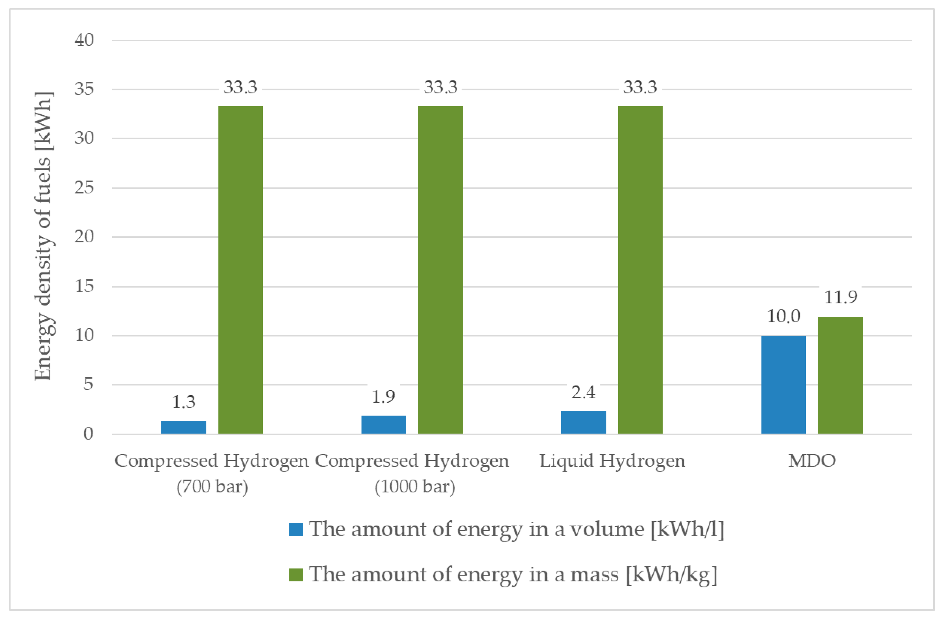
A comparison of the energy density of fuels, including compressed and liquid hydrogen and conventional MDO fuel, is shown in Figure 15.
Figure 15 shows that an increase in hydrogen compression pressure causes an increase in energy density in relation to volume, and at a compressed hydrogen pressure of approximately 1234 bar, the energy density would be the same as for liquid hydrogen. However, the energy density in relation to volume for liquid hydrogen is approximately ¼ of that for MDO.
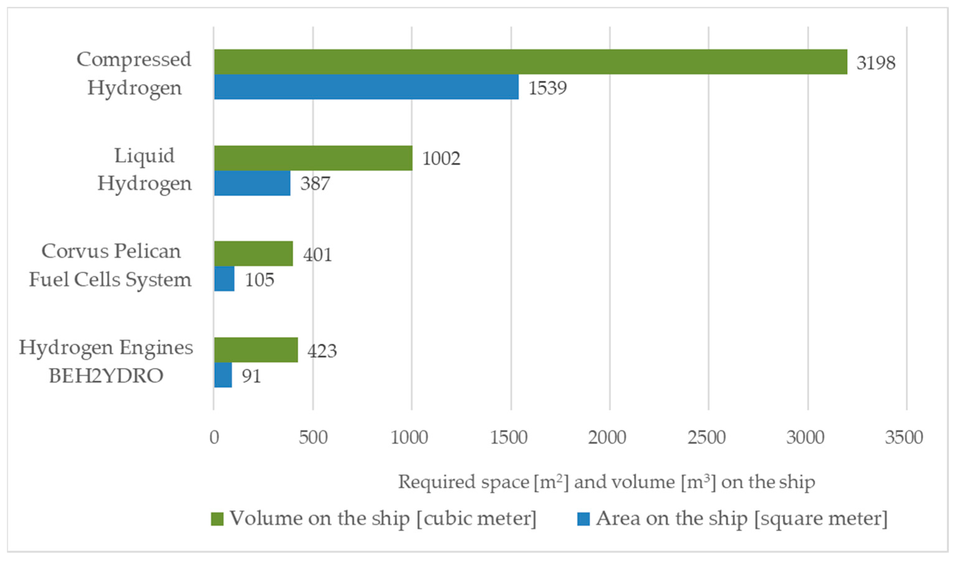
Figure 16 and Figure 17 show the masses and the space and volume occupied by the generator sets and fuel cells, as well as a comparison of these parameters with the mass, space and volume of compressed and liquefied hydrogen, together with their tanks, necessary to complete a 14-day SOV mission.
Figure 16 shows that hydrogen tanks and related equipment, in particular CH2 cylinders with racks, account for the largest proportion of the ship’s total displacement. It follows from Figure 17 that liquefied hydrogen (LH2) requires less storage space than compressed hydrogen (CH2), which occupies more than three times the volume and four times the surface area on the ship.
Of the examined energy solutions, fuel cells have the lowest space requirements, with slightly lower weight and volume, although the surface area occupied is slightly larger than in the case of BEH2YDRO hydrogen-powered engines, which makes them a better solution in terms of compactness.
Figure 18 depicts the required mass and volume of compressed and liquid hydrogen compared to MDO fuel for a 14-day SOV mission.
Figure 18 shows that compressed hydrogen occupies the largest volume, MDO has the highest mass, and hydrogen tanks, particularly CH2 cylinders with racks, exhibit a very high mass.

5. Conclusions

Hydrogen-powered service operation vessels (SOVs) are an important step towards decarbonising the maritime sector. Design analyses have shown that hydrogen fuel cell technology can be effectively integrated into existing propulsion systems, offering flexibility and reduced emissions. The combustion of hydrogen or its conversion in fuel cells does not generate CO2, and the only by-product is water vapour—hydrogen is therefore a zero-emission fuel.
Initial research has been conducted on the use of hydrogen as a fuel for SOVs with specific dimensions and operating parameters on 14-day missions to support wind farms in the Baltic Sea. These analyses considered the transport and storage of hydrogen in liquid form (LH2) in cryogenic tanks, supplying the energy system in the form of hydrogen fuel cells. Their results also served as a comparison to earlier studies, which dealt with hydrogen storage in compressed form (CH2) in high-pressure tanks and the use of hydrogen-powered internal combustion engines.
Analyses indicate that the use of compressed hydrogen (CH2) is impractical, as it would require storage tanks occupying as much as 64% of the vessel’s payload capacity and 66% of its volume, making mission execution impossible. In contrast, liquid hydrogen (LH2) allows for more than a threefold reduction in tank mass and volume, enabling 9 ÷ 10 days of autonomous operation, albeit at the expense of reducing the functionality of the working deck by more than half. The limitation results mainly from the lack of precise and clearly formulated IMO regulations concerning the location of hydrogen tanks inside the hull.
The key factors in choosing one variant remain costs of operations and those of the entire supply chain, as well as the market price of hydrogen. LH2 is estimated to be more expensive than CH2 due to the costs of liquefaction and the demanding storage technology. The research results highlight that under current economic conditions, the cost of LH2 (at a minimum price of approx. 3.80 EUR/kg) remains over 500% higher than the cost of MDO for a single SOV mission. However, the development of offshore wind farms may significantly reduce the price of “green” hydrogen in the future, potentially making it competitive.
In terms of propulsion equipment, while maintaining the same power of the SOV’s energy system, hydrogen fuel cells occupy on average 13.7% more space than internal combustion engines, but are on average 24.3% lower and 50.6% lighter (depending on the fuel cell and combustion engine model, this is 20% or 73.3%), which provides some weight savings that can be used in the engine room, e.g., for a battery energy storage system or simply for use in the ship’s cargo space. The modular design of hydrogen fuel cells allows them to be freely arranged in the engine room, which helps to optimise the spatial layout. In addition, their use simplifies the installations supporting the power plant’s energy equipment (no need for exhaust gas installations, lubrication systems or an extensive compressed air system), which can free up additional space and reduce the weight of the power plant.
The conducted research provides important practical implications, including:
  • Indicating technologies that can be realistically implemented on SOVs and identifying limitations that should be considered already at the vessel design stage. At present, the storage of LH2 has greater application potential for service vessels than CH2, as it enables a significant reduction in tank mass and volume.
  • Demonstrating that the application of hydrogen fuel cells on SOVs offers substantial operational benefits, as they are characterised by lower weight, modular construction and simpler power plant infrastructure compared to internal combustion engines. This provides designers with greater flexibility in arranging machinery spaces and optimising spatial layouts, thereby increasing the vessel’s usable area.
  • Revealing IMO regulatory constraints, including the absence of precise guidelines regarding the location of hydrogen tanks within the ship’s hull, which represents a significant barrier to the design of such vessels. Thus, the results may contribute to confirming the need to accelerate the development of safety standards for hydrogen, which is undoubtedly a future-oriented and zero-emission fuel.
The research has also shown the potential of offshore wind farms as hydrogen bunkering stations, based on seawater electrolysis, which would allow hydrogen refuelling at sea and significantly increase the autonomy of offshore vessels.
The authors, in pursuit of optimal SOV operation, point to the potential of hybrid solutions such as H2PowerPac and Battery PowerPac modules, which, when integrated with the fuel cell energy system and optionally internal combustion engines, can effectively extend vessel autonomy, reduce dependence on port infrastructure and increase operational flexibility.
The first solution (H2PowerPac) comprises modular hydrogen generators available in the form of 20-foot containers with CH2. These enable rapid transfer and exchange of storage units during missions, without the need to build permanent bunkering infrastructure, thereby significantly enhancing vessel operability [79]. The second solution (Battery PowerPac) is an energy storage system installed below deck or as interchangeable container modules on the vessel’s deck. It can supply ship systems during port stays, support the main energy system during peak power demand, and, under low-load conditions, allow fuel cells or generators to charge the batteries contained in the module [80].
It is also important to remember the extremely important implementation of energy management systems (BMS), taking into account the monitoring of the operating temperature of the cells and its impact on their durability and efficiency [63].
All of these activities could enable the 14-day SOV mission requirement to be met.
In summary, this study provides a practical contribution by delivering detailed comparative data applicable to SOV design, hydrogen bunkering infrastructure planning, and the development of international regulations on the safe use of hydrogen in maritime operations.

Author Contributions

Conceptualization, M.B. and A.Z.; Methodology, M.B. and A.Z.; Software, M.B. and A.Z.; Formal analysis, M.B. and A.Z.; Writing—original draft, M.B. and A.Z.; Writing—review & editing, M.B. and A.Z.; Visualization, M.B. and A.Z.; Supervision, M.B. and A.Z. All authors have read and agreed to the published version of the manuscript.

Funding

This research received no external funding.

Data Availability Statement

The original contributions presented in this study are included in the article. Further inquiries can be directed to the corresponding author.

Conflicts of Interest

The authors declare no conflicts of interest.

References

  1. DNV. Handbook for Hydrogen-Fuelled Vessels, MarHySafe JDP Phase 11st Edition (June 2021). Available online: https://www.dnv.com/maritime/publications/handbook-for-hydrogen-fuelled-vessels-download (accessed on 10 April 2025).
  2. DNV. Industry Insights Decarbonization Digitalization. Strategies for Meeting Upcoming Decarbonization Targets. Available online: https://www.dnv.com/expert-story/maritime-impact/strategies-for-meeting-upcoming-decarbonization-targets (accessed on 1 May 2025).
  3. IEA. Global Hydrogen Review 2024. Available online: https://www.iea.org/reports/global-hydrogen-review-2024 (accessed on 10 April 2025).
  4. Potential of Hydrogen as Fuel for Shipping by ABS. CE DELFT & ARCSILEA. European Maritime Safety Agency EMSA/Hydrogen—2022/2023—4837444, 31 August 2023. Available online: https://emsa.europa.eu/publications/reports/item/5062-potential-of-hydrogen-as-fuel-for-shipping.html (accessed on 10 April 2025).
  5. IRENA. International Renewable Energy Agency. Available online: https://www.irena.org/Innovation-landscape-for-smart-electrification/Power-to-hydrogen (accessed on 5 June 2025).
  6. ABI Research. The Tech Intelligence Experts. Available online: https://www.abiresearch.com/press/green-hydrogen-costs-of-production-to-drop-to-us25kg-by-2030-and-us180-by-2040-clearing-the-way-for-heavy-industry-decarbonization (accessed on 5 June 2025).
  7. De Witte E.—CNB nv. Low Emission Vessel Hydroville. CMB Technologies. De Gerlachekaai 20, Antwerpen, Belgium. 2000. Available online: https://www.hylaw.eu/files/2018-12/2.%20CMB%20Technologies%20-%20HyLaw.pdf (accessed on 10 April 2025).
  8. NORLED. Available online: https://www.norled.no/en/nyhet/mf-hydra-the-worlds-first/ (accessed on 10 April 2025).
  9. Ballard Power Systems. Available online: https://blog.ballard.com/marine/worlds-first-liquid-powered-hydrogen-ship-mf-hydra-is-powered-by-ballards-fuel-cells (accessed on 10 April 2025).
  10. Ballard Website—Ballard’s FCwave™ Receives Type Approval from Lloyd’s Register. Available online: https://blog.ballard.com/marine/ballards-fcwave-receives-type-approval-from-lloyds-register (accessed on 21 July 2025).
  11. MarineLink. Available online: https://www.marinelink.com/news/osv-operates-green-hydrogen-518041 (accessed on 10 April 2025).
  12. OffshoreWIND.biz. Available online: https://www.offshorewind.biz/2024/03/19/louis-dreyfus-armateurs-unveils-liquid-hydrogen-sov-concept (accessed on 10 April 2025).
  13. Vessel Finder. Available online: https://www.vesselfinder.com/pl/vessels/details/9186077 (accessed on 5 May 2025).
  14. Eidesvik Offshore Website—Viking Energy. Available online: https://eidesvik.no/vessels/viking-energy (accessed on 10 July 2025).
  15. ShipFC Website—Temporary Suspension for ShipFC Project. Available online: https://shipfc.eu/temporary-suspension-for-shipfc-project (accessed on 10 July 2025).
  16. Ulstein Website—SX190. Available online: https://ulstein.com/vessels/sx190 (accessed on 10 July 2025).
  17. Fuel Cells: Addressing the Key Technical Challenges. Part of “Maritime Hybrid, Electric and Fuel Cells” Webinar Week 1–4 June 2020. Roadmap to a Hydrogen Future—ULSTEIN SX190. Available online: https://dvzpv6x5302g1.cloudfront.net/AcuCustom/Sitename/DAM/076/3rd_Fuel_Cells_Addressing_the_key_technical_challenges.pdf (accessed on 10 July 2025).
  18. Nedstack Website—Zero-Emission Operations in Offshore Construction Market. Available online: https://nedstack.com/en/news/zero-emission-operations-offshore-construction-market (accessed on 10 July 2025).
  19. Bortnowska, M.; Zmuda, A. The Possibility of Using Hydrogen as a Green Alternative to Traditional Marine Fuels on an Offshore Vessel Serving Wind Farms. Energies 2024, 17, 5915. [Google Scholar] [CrossRef]
  20. Melideo, D.; Desideri, U. The use of hydrogen as alternative fuel for ship propulsion: A case study of full and partial retrofitting of roll-on/roll-off vessels for short distance routes. Int. J. Hydrogen Energy 2024, 50 Pt B, 1045–1055. Available online: https://www.sciencedirect.com/science/article/pii/S0360319923052503 (accessed on 10 April 2025). [CrossRef]
  21. Liu, X.; Yang, G.; Sun, B.; Wang, H.; Li, Y.; Wang, R. Assist in GHG Abatement of Offshore Ships: Design and Economic Analysis of an Integrated Utilization Model of hydrogen-powered Ship and Offshore Wind Power. Sustain. Mar. Struct. 2023, 5, 15–25. [Google Scholar] [CrossRef]
  22. Di Micco, S.; Minutillo, M.; Forcina, A.; Cigolotti, V.; Perna, A. Feasibility analysis of an innovative naval onboard power-train system with hydrogen-based PEMFC technology. E3S Web Conf. 2021, 312, 07009. [Google Scholar] [CrossRef]
  23. Aziz, M. Liquid Hydrogen: A Review on Liquefaction, Storage. Energies 2021, 14, 5917. Available online: https://www.mdpi.com/1996-1073/14/18/5917 (accessed on 10 April 2025). [CrossRef]
  24. Levikhin, A.A.; Boryae, A.A. Physical properties and thermodynamic characteristics of hydrogen. Heliyon 2024, 10, e36414. Available online: https://www.sciencedirect.com/science/article/pii/S2405844024124450 (accessed on 10 April 2025). [CrossRef]
  25. Institution of Gas Engineers and Managers. IGEMHydrogen-CharacteristicsandImplications.pdf. IGEM Technical Paper, August 2022. Available online: https://www.igem.org.uk/resource-report/igem-hydrogen-characteristics-and-implications-technical-paper.html (accessed on 20 March 2025).
  26. Momirlan, M.; Veziroglu, T.N. The properties of hydrogen as fuel tomorrow in sustainable energy system for a cleaner planet. Int. J. Hydrogen Energy 2005, 30, 795–802. [Google Scholar] [CrossRef]
  27. Shadidi, B.; Najafi, G.; Yusaf, T. A Review of Hydrogen as a Fuel in Internal Combustion Engines. Energies 2021, 14, 620. Available online: https://www.mdpi.com/1996-1073/14/19/6209 (accessed on 10 April 2025). [CrossRef]
  28. Yang, N.; Deng, J.; Wang, C.; Bai, Z.; Qu, J. High pressure hydrogen leakage diffusion. Research progress. Int. J. Hydrogen Energy 2024, 50 Pt A, 1029–1046. [Google Scholar] [CrossRef]
  29. Menon, S.K.; Kumar, A.; Mondal, S. Advancements in hydrogen gas leakage detection sensor technologies and safety measures. Clean Energy 2025, 9, 263–277. [Google Scholar] [CrossRef]
  30. Van Hoecke, L.; Laffineur, L.; Campe, R.; Perreault, P.; Verbruggen, S.W.; Lenaerts, S. Challenges in the use of hydrogen for maritime applications. Energy Environ. Sci. 2020, 14, 815–843. [Google Scholar] [CrossRef]
  31. Kanchiralla, F.M.; Brynolf, S.; Malmgren, E.; Hansson, J.; Grahn, M. Life-cycle assessment and costing of fuels and propulsion systems in future fossil-free shipping. Environ. Energy Clim. 2022, 56, 12517–12531. Available online: https://www.researchgate.net/publication/362880292_Life-Cycle_Assessment_and_Costing_of_Fuels_and_Propulsion_Systems_in_Future_Fossil-Free_Shipping (accessed on 20 June 2025). [CrossRef]
  32. Branwen Ap, D.T.; Stamford, L.; Welflea, A.; Larkin, A. Decarbonising international shipping—A life cycle perspective on alternative fuel options. Energy Convers. Manag. 2024, 299, 117848. [Google Scholar] [CrossRef]
  33. Nykiel, D.; Zmuda, A.; Abramowski, T.A. Sustainability-Driven Approach to Early-Stage Offshore Vessel Design: A Case Study on Wind Farm Installation Vessels. Sustainability 2025, 17, 2752. [Google Scholar] [CrossRef]
  34. DNV, IMO CCC 10: Interim Guidelines for Ammonia and Hydrogen as Fuel. Available online: https://www.dnv.com/news/2024/imo-ccc-10-interim-guidelines-for-ammonia-and-hydrogen-as-fuel (accessed on 8 September 2025).
  35. Advanced Biofuels USA, Practical Guide for Approval of Ammonia or Hydrogen Fuelled Ships Practical Guide for Approval of Ammonia or Hydrogen Fuelled Ships. Available online: https://www.imo.org/en/mediacentre/meetingsummaries/pages/ccc-10th-session.aspx (accessed on 9 September 2025).
  36. IMO, Sub-Committee on Carriage of Cargoes and Containers (CCC 9), 9th Session, 20–29 September 2023. Available online: https://www.imo.org/en/mediacentre/meetingsummaries/pages/ccc-9th-session.aspx (accessed on 9 September 2025).
  37. IGF Code (MSC.391(95))—International Code of Safety for Ships Using Gases or Other Low-flashpoint Fuels (SOLAS). Available online: https://puc.overheid.nl/nsi/doc/PUC_80736_14/1/ (accessed on 7 September 2025).
  38. IMO, MSC.1/Circ.1647 15 June 2022, Interim Guidelines for the Safety of Ships Using Fuel Cell Power Installations. Available online: https://www.register-iri.com/wp-content/uploads/MSC.1-Circ.1647.pdf (accessed on 9 September 2025).
  39. DNV Handbook. Guidance for Hydrogen-Fuelled Vessels, DNV Class Rules Updates. 2024. Available online: https://www.dnv.com/news/2024/now-available-july-2024-edition-of-the-dnv-class-rules-for-ships-and-offshore-units/ (accessed on 7 September 2025).
  40. DNV, Practical Guide for Approval of Ammonia- or Hydrogen-Fuelled Ships. Available online: https://www.dnv.com/expert-story/maritime-impact/practical-guide-for-approval-of-ammonia-or-hydrogen-fuelled-ships (accessed on 9 September 2025).
  41. Bureau Veritas—Rule Notes/NR678 Hydrogen-Fuelled Ships. NR678 Hydrogen-Fuelled Ships|Marine & Offshore. Available online: https://marine-offshore.bureauveritas.com/nr678-hydrogen-fuelled-ships (accessed on 7 September 2025).
  42. ABS, Advisory on Gas and Other Low Flashpoint Fuels. Available online: https://ww2.eagle.org/content/dam/eagle/advisories-and-debriefs/gas-and-low-flashpoint-fuels-advisory.pdf (accessed on 9 September 2025).
  43. ISO 21009 (Parts 1 & 2); Static Vacuum-Insulated Cryogenic Vessels. ISO 21009-1:2022—Cryogenic Vessels—Static Vacuum-Insulated Vessels—Part 1: Design, Fabrication, Inspection and Tests. International Organization for Standardization: Geneva, Switzerland. Available online: https://www.iso.org/standard/76098.html (accessed on 7 September 2025).
  44. Ronevich, J.; San Marchi, C. Materials Performance at Liquid Hydrogen Temperatures. Liquid Hydrogen Technologies Virtual Workshop, 22–23 February 2022. Available online: https://www.energy.gov/sites/default/files/2022-03/Liquid%20H2%20Workshop-SNL.pdf (accessed on 9 September 2025).
  45. ISO 21011:2008; Cryogenic Vessels—Valves for Cryogenic Service. ISO: Switzerland, Geneva, 2008.
  46. EN 13445-1:2021; Unfired Pressure Vessels—Part 1: General. CEN: Brussels, Belgium, 2021.
  47. Kim, M.-S.; Chun, K.W. A Comprehensive Review on Material Compatibility and Safety Standards for Liquid Hydrogen Cargo and Fuel Containment Systems in Marine Applications. J. Mar. Sci. Eng. 2023, 11, 1927. [Google Scholar] [CrossRef]
  48. Hexagon Purus. Available online: https://hexagonpurus.com/our-solutions/hydrogen-type-4-cylinders (accessed on 21 March 2025).
  49. Linde Engineering. Available online: https://www.linde-engineering.com/products-and-services/plant-components/liquefied-hydrogen-tank-solutions (accessed on 21 March 2025).
  50. Linde. Available online: https://www.scribd.com/document/533566986/Day2-1105-Decker-Liquid-hydrogen-distribution-technology-Linde (accessed on 21 March 2025).
  51. Guan, W.; Chen, L.; Wang, Z.; Chen, J.; Ye, Q.; Fan, H. A 500 kW hydrogen fuel cell-powered vessel: From concept to sailing. Int. J. Hydrogen Energy 2024, 89, 1466–1481. Available online: https://www.sciencedirect.com/science/article/pii/S0360319924041430 (accessed on 21 March 2025). [CrossRef]
  52. Kołodziejski, M. Review of hydrogen-based propulsion systems in the maritime sector. Arch. Thermodyn. 2024, 44, 335–380. [Google Scholar] [CrossRef]
  53. Karvounis, P.; Tsoumpris, C.; Boulougouris, E.; Theotokatos, G. Recent advances in sustainable and safe marine engine operation with alternative fuels. Front. Mech. Eng. 2022, 8, 994942. [Google Scholar] [CrossRef]
  54. Minutillo, M.; Cigolotti, V.; Di Ilio, G.; Bionda, A.; Boonen, E.-J.; Wannemacher, T. Hydrogen-based technologies in maritime sector: Technical analysis and prospective. E3S Web Conf. 2022, 334, 06011. [Google Scholar] [CrossRef]
  55. Elkafas, A.G.; Rivarolo, M.; Gadducci, E.; Magistri, L.; Massardo, A.F. Fuel Cell Systems for Maritime: A Review of Research Development, Commercial Products, Applications and Perspectives. Processes 2023, 11, 97. [Google Scholar] [CrossRef]
  56. Ballard Website—FCwave™—Heavy-Duty Marine & Stationary Power Fuel Cell Modules. Available online: https://www.ballard.com/fcwave (accessed on 20 July 2025).
  57. Corvus Energy Website—Pelican Marine Fuel Cell System. Available online: https://corvusenergy.com/products/corvus-pelican-marine-fuel-cell-system (accessed on 20 July 2025).
  58. PowerCell Group Website—Introducing Our Marine Power Evolution Marine System 225. Available online: https://powercellgroup.com/solutions/marine-system-225 (accessed on 20 July 2025).
  59. Nedstack Website—PemGen Mobile. Available online: https://nedstack.com/en/pemgen-solutions/maritime-power-installations/pemgen-mobile (accessed on 20 July 2025).
  60. Horizon Website—Full Cell Systems. Available online: https://www.horizonfuelcell.com/fuelcellsystems (accessed on 20 July 2025).
  61. Bloom Energy Website—Hydrogen Fuel Cells for a Decarbonized Future. Available online: https://www.bloomenergy.com/hydrogen-fuel-cells (accessed on 20 July 2025).
  62. Catalog “Marine System 225”; PowerCell Group: Gothenburg, Sweden, 2025; Available online: https://press.powercellgroup.com/en/marine-system-225 (accessed on 20 July 2025).
  63. Jia, C.; Liu, W.; He, H.; Chau, K.T. Health-conscious energy management for fuel cell vehicles: An integrated thermal management strategy for cabin and energy source systems. Energy 2025, 333, 137330. [Google Scholar] [CrossRef]
  64. HydrogenTech Website—Ogniwa Paliwowe SOFC rDSC. Available online: https://hydrogentech.pl/project/ogniwa-paliwowe-sofc-rdsc (accessed on 20 July 2025).
  65. Łukasiewicz—Instytut Chemii Przemysłowej Im. Prof. Ignacego Mościckiego Website—Własne Ogniwa Paliwowe—Coraz Bliżej. Available online: https://ichp.lukasiewicz.gov.pl/2021/07/19/wlasne-ogniwa-paliwowe-coraz-blizej (accessed on 20 July 2025).
  66. Klebanoff, L.E.; Caughlan, S.A.M.; Madsen, R.T.; Conard, C.J.; Leach, T.S.; Appelgate, T.B., Jr. Comparative study of a hybrid research vessel utilizing batteries or hydrogen fuel cells. Int. J. Hydrogen Energy 2021, 46, 38051–38072. [Google Scholar] [CrossRef]
  67. Zhou, Z.; Tao, J. Hydrogen-powered vessels in green maritime decarbonization: Policy drivers, technological frontiers and challenges. Front. Mar. Sci. 2025, 12, 1601617. [Google Scholar] [CrossRef]
  68. Zéphyr & Borée Website—ZEPH2: CTV Diesel-Hydrogen Hybrid. Available online: https://zephyretboree.com/en/projects/h2ermine (accessed on 9 September 2025).
  69. FuelCellsWorks Website—Completion of the ZEPH2 Project: Decarbonized Offshore Maintenance Vessel with Hybrid Hydrogen Propulsion. Available online: https://fuelcellsworks.com/news/completion-of-the-zeph2-project-decarbonized-offshore-maintenance-vessel-with-hybrid-hydrogen-propulsion (accessed on 9 September 2025).
  70. UC San Diego Website—Design of World’s First Hydrogen-Hybrid Research Vessel Approved. Available online: https://today.ucsd.edu/story/design-of-worlds-first-hydrogen-hybrid-research-vessel-approved (accessed on 9 September 2025).
  71. Mylonopoulos, F.; Durgaprasad, S.; Coraddu, A.; Polinder, H. Lifetime design, operation, and cost analysis for the energy system of a retrofitted cargo vessel with fuel cells and batteries. Int. J. Hydrogen Energy 2024, 91, 1262–1273. [Google Scholar] [CrossRef]
  72. Bortnowska, M. Projected Reductions in CO2 Emissions by Using Alternative Methanol Fuel to Power a Service Operation Vessel. Energies 2023, 16, 7419. [Google Scholar] [CrossRef]
  73. Hexagon Purus. Type 4 Infrastructure and Mobility–Hexagon Purus Datasheet. April 2024. Available online: https://hexagonpurus.com/our-solutions/download-our-brochures/datasheets (accessed on 25 March 2022).
  74. BEH2YDRO Engines Catalog “Information Sheet”; Anglo Belgian Corporation: Gent, Belgium, 2022; Available online: https://www.production.behydro.be/uploads/files/DATASHEETS-Behydro.pdf (accessed on 22 July 2025).
  75. Engines Catalog “Wärtsilä 20DF”; Wärtsilä Corporation: Helsinki, Finland, 2023; Available online: https://s6ca5bb3203b5f73d.jimcontent.com/download/version/1609518835/module/12717787226/name/Wartsila%2020DF%20Marine%20Engine%20Product%20Guide.pdf (accessed on 22 July 2025).
  76. KHL Power Division Website—Ballard Wins Type Approval for Marine Fuel Cell Module. Available online: https://www.powerprogress.com/news/ballard-wins-type-approval-for-marine-fuel-cell-module/8019720.article (accessed on 22 July 2025).
  77. Bunker Ports News Worldwide Website—Rotterdam Bunker Prices. Available online: https://www.bunkerportsnews.com/PortBunkerPrices.aspx?ElementID=93458966-d962-468c-b9ef-1a143bf22d1b (accessed on 29 July 2025).
  78. Business Analytiq Website—Green Hydrogen Price Index. Available online: https://businessanalytiq.com/procurementanalytics/index/green-hydrogen-price-index (accessed on 29 July 2025).
  79. eCap Marine Website—Embrace the Future with Zero-Emission Hydrogen Power Generator. Available online: https://ecap-marine.com/products/hydrogen-power-generator.html (accessed on 22 July 2025).
  80. eCap Marine Website—Battery Energy Storage System—BESS. Available online: https://ecap-marine.com/solutions/battery-energy-storage-system-bess.html (accessed on 22 July 2025).
Figure 1. Alternative fuel uptake in the world fleet in number of ships, acc. [2].
Energies 18 05104 g001
Figure 2. General concept of the power system of the MF Hydra ferry [10].
Energies 18 05104 g002
Figure 3. Physical methods of hydrogen storage [authors’ work].
Energies 18 05104 g003
Figure 4. Example of the general design of a PowerCell fuel cell system [62].
Energies 18 05104 g004
Figure 5. Example power and efficiency characteristics of PowerCell fuel cells [62].
Energies 18 05104 g005
Figure 6. SOV service workflow diagram divided into individual operating states (authors’ work).
Energies 18 05104 g006
Figure 7. Block diagram of the methodology for analysing hydrogen use on SOVs—comparative and variant analysis (authors’ work).
Energies 18 05104 g007
Figure 8. Example diagram of an energy system with three fuel cell systems [authors’ work].
Energies 18 05104 g008
Figure 9. An array of 6 Pelican fuel cell modules from Corvus [57] and a Ballard FCwave™ module in the background [76]: (a) six Corvus Pelican fuel cell modules, (b) Ballard fuel cell module.
Energies 18 05104 g009
Figure 10. Calculated LH2 and CH2 hydrogen reserve and hydrogen tank volume for ship autonomy (1 ÷ 14 days).
Energies 18 05104 g010
Figure 11. Deck space occupied by LH2 vs. CH2 tank systems and their percentage share for ship autonomy (1 ÷ 14 days).
Energies 18 05104 g011
Figure 12. Example visualisation of a cryogenic tank—illustrative figure, acc. [73] [authors’ work].
Energies 18 05104 g012
Figure 13. Layout of cryogenic tanks and hydrogen fuel cell system—longitudinal section (illustrative figure [authors’ work]).
Energies 18 05104 g013
Figure 14. Layout of cryogenic tanks—view of the working deck (illustrative figure [authors’ work]).
Energies 18 05104 g014
Figure 15. Comparison of the energy density of compressed and liquid hydrogen relative to MDO [authors’ work].
Energies 18 05104 g015
Figure 16. Comparison mass of power equipment and hydrogen supply for a 14-day SOV mission [authors’ work].
Energies 18 05104 g016
Figure 17. Area and volume of power equipment and hydrogen storage for a 14-day SOV mission [authors’ work].
Energies 18 05104 g017
Figure 18. Comparison of mass and volume of compressed and liquid hydrogen compared to MDO fuel for a 14-day SOV mission [authors’ work].
Energies 18 05104 g018
Table 2. Comparison of Hydrogen Characteristics in Gaseous and Liquid Forms in Relation to Their Applications.
No.Aspect/CriteriaCompressed Hydrogen (CH2)Liquefied Hydrogen (LH2)
1.Volumetric EfficiencyOccupies a large volumeMore compact/Higher volumetric density
2.System ComplexityRelatively simple (no need for cryogenics)High—requires cooling and insulation
3.SafetyCan rapidly decompress and ignite/Possible tank explosionHigher risks due to low temperature/Evaporation may cause flammable gas buildup/Risk of frostbite, material cracking
4.ApplicationsShort-range ferries, passenger ships, offshore vesselsLarge ocean-going ships, tankers, container ships
5.Transport EfficiencyLow suitability for long distances/Short-sea shippingBetter for large volumes/Suitable for long endurance at sea
6.BunkeringFaster and easierSlower and more technically demanding
7.Operating PressureVery high: 350–700 barLow pressure, but extremely low temperature ~ −253 °C
8.Tank ConstructionMuch thicker walls, heavy constructionThinner tanks, with cryogenic insulation
9.Tank Mass to Hydrogen Mass RatioUp to 14:1 or higherAround 7:1 or even 5:1
10.Infrastructure/CostsEasy to store/Cheaper storage infrastructureComplex infrastructure/Higher cost due to complexity of cooling systems and tanks
Table 3. Safety considerations for the use of cryogenic hydrogen on ships, acc. [37,39,40,41,42,43,44].
No.Safety Focus AreasLiquefied Hydrogen (LH2)
1.Boil-off Gas (BOG)Hydrogen evaporates due to heat ingress or loss of insulation. Each tank must be equipped with safety valves (PRV—Pressure Relief Valve, TPRD—Thermal Pressure Relief Device) and a gas discharge system designed for extreme scenarios, such as complete vacuum loss. Outlets should be routed to ventilation masts, with priority given to using BOG in internal combustion engines or fuel cells, followed by compression or safe release.
2.Cryogenics (Tanks)Vacuum-insulated tanks compliant with ISO 21009 [43] and ISO 21011 [45] are used. Key aspects include vacuum monitoring, prevention of atmospheric moisture condensation and secondary barriers to protect the hull. A defined emergency procedure is also required in the event of insulation failure.
3.MaterialsSteels and alloys must withstand extremely low temperatures (−253 °C) and resist hydrogen embrittlement, i.e., they must not crack under hydrogen exposure. Austenitic stainless steels, such as 304L and 316L (corrosion-resistant, easily weldable and formable), are commonly used. Aluminium and nickel alloys are also applied. All materials must be qualified for cryogenic conditions in accordance with standards such as ISO 21009, EN 13445 [46] and ASME (American Society of Mechanical Engineers).
4.Detection and VentilationHydrogen sensors must be installed in locations where gas may accumulate. The ventilation system must ensure dilution below the lower explosive limit. Hazard zones and emergency systems must cut off fuel supply upon problem detection.
Table 4. General characteristics of tanks for two forms of hydrogen [47,48,49,50].
No.Form of
Hydrogen
General Characteristics of Hydrogen Tanks
1.Compressed gas CH2High-pressure composite tanks—type IV, highly durable, lightweight compared to steel tanks. They consist of a plastic liner, which serves as an inner container preventing hydrogen permeation but cannot withstand pressure on its own; a main load-bearing layer—usually made of carbon fibre, sometimes with the addition of glass fibre, which absorbs high pressure.
Safety features: pressure relief valves, hydrogen detectors.
2.Cryogenic liquid LH2Tanks are usually cylindrical in shape. Their construction is multi-layered: an inner layer (liner) made of low-temperature resistant and hydrogen-tight materials (stainless steel/aluminium alloys); vacuum insulation between the tank walls, consisting of several layers of heat-reflecting metabolised foil; outer shell is made of stainless steel/composite, providing mechanical and environmental protection for the entire structure.
Safety features: safety valves, gas ventilation systems, temperature and pressure sensors, emergency gas discharge systems.
Table 5. Tally of the main fuel cell technologies and their general characteristics [55].
No.FC TypeTemperature [°C]ElectrolyteTypical FuelPower RangeElectrical
Efficiency
Applications
1.PEMFC60 ÷ 80
110 ÷ 180
Water-based polymer membraneHydrogenUp to 1 MW
(up to 200 kW
per module)
45 ÷ 55%Backup power, Portable power, Distributed generation, Transportation, Specialty vehicles
2.SOFC500 ÷ 1 000Porous ceramic materialHydrogen, methanol, hydrocarbonsUp to 1 MW
(up to 250 kW
per module)
50 ÷ 60%Auxiliary power, Electric utility, Distributed generation
3.MCFC650 ÷ 800Molten carbonate saltHydrogen, methanol, hydrocarbonsUp to 1 MW
(up to 250 kW
per module)
43 ÷ 55%Electric utility, Distributed generation
4.PAFC140 ÷ 200Phosphoric acidHydrogen, LNG, methanolUp to 11 MW (100 ÷ 400 kW
per module)
30 ÷ 42%Distributed generation
5.AFC60 ÷ 200Potassium hydroxideHydrogenUp to 0.5 MW
(up to 100 kW
per module)
40 ÷ 50%Military and space applications, Backup power, Transportation
Table 6. Tally of the properties of PEMFC and SOFC fuel cells [55,56,57,58,59,60,61].
No.FC SupplierModelPower
[kW]
Efficiency
[%]
Power Density
[kW/tona]/[kW/m3]
Voltage Range
[V]
Current Range
[A]
1.PEMFC
2.BallardFCwave20053.5200/102350 ÷ 7200 ÷ 550
3.Corvus EnergyPelican Marine FCS340≥5090.7/47.5400 ÷ 750-
4.PowerCellMarine System 22522556184/104430 ÷ 91045 ÷ 450
5.NedstackPemGen15051176.5/1308000 ÷ 255
6.HorizonVLIII200-50200≥43760/299500 ÷ 7500 ÷ 500
7.SOFC
8.Bloom EnergyBloom3005219/10.2480-
Table 7. Tally of the properties of selected PEMFC fuel cells [56,57,58].
No.ParametrFuel Cell Manufacturer
Ballard’s Power System, FCwave™Corvus Pelican Fuel Cell System (FCS)PowerCell Marine
System 225
1.FC Power NFC [kW]200340225
2.Dimensions
L × W × H [mm]
1209 × 741 × 21952160 × 1427 × 23201165 × 915 × 2032
3.Weight WE [t]1.03.751.22
4.Type of Fuel CellPEMFCPEMFCPEMFC
5.Fuel typeHydrogen (H2)Hydrogen (H2)Hydrogen (H2)
6.Hydrogen Inlet Pressure [bar.g]3.5 ÷ 6.55.4 ÷ 14.03.0 ÷ 8.0
7.Output Voltage
[V DC]
350 ÷ 720400 ÷ 750430 ÷ 775 (910)
8.Maximum Efficiency [%]53.55256
9.Marine CertificationDNV, Lloyd’s Register, ABSDNVLloyd’s Register
Table 8. Main technical data of auxiliary generators [56,57,74,75].
No.ParameterEngine TypeFuel Cell Type
Dual-Fuel Engine (Wärtsilä 9L20DF)Hydrogen Engine (BEH2YDRO 12DZD H2)Corvus Pelican Fuel Cell SystemBallard’s Power
System, FCwave™
1.Power
NAP [kW]
3 × 17553 × 18003 × 1700 (5 × 340)
(plus 1 × 340)
4 × 1200 (6 × 200)
1 × 600 (3 × 200)
2.Total Power NC [kW]5265540054405400
3.Dimensions
L × B × H [mm]
6700 × 2010 × 28316667 × 1850 × 31317135 × 2160 × 23207254 × 741 × 2195
4.Occupied
Area * [m2]
95.9691.44104.87108.32
5.Weight ME [t]3 × 25
total 75
3 × 33.7
total 101.1
16 × 3.75
total 60
27 × 1.0
total 27
6.Type of Fuel Cell--PEMFCPEMFC
7.Fuel TypeLNG, MDO, HFOH2, MDO, LFOHydrogen (H2)Hydrogen (H2)
8.IMOTier II or IIITier IIIZero-emissionZero-emission
* the occupied area includes devices (engines or fuel cells) and service space, according to the design analysis.
Table 9. Estimated total fuel reserve and volume for a 14-day mission.
No.ParameterFuelsThe Ratio of H2 to MDO for:
Hydrogen CH2Hydrogen LH2MDOCH2LH2
1.Total fuel reserve M T f u e l [ t ] 42.4640.76115.850.370.35
2.Fuel volume Vfuel [m3]1056.13599.29137.927.664.17
3.Emergency Content LHV [MJ/kg]12012043
4.Fuel consumption per hour Gfuel [kg/h]97.8393.91266.94
5.Specific fuel consumption g f u e l [g/kWh]67.9365.22189.59
6.Density [kg/m3]40.270.85840
7.Area required for a 14-day
mission (tanks + compartments required) [m2]
acc. to design analysis
1539387230
Table 10. Required hydrogen volume and number of LH2 tanks versus CH2 cylinders for ship autonomy (1 ÷ 14 days).
No.EnduranceHydrogen Volume [m3]Hydrogen
Volume CH2 Minus
MDO [m3]
Number of Tanks LH2/
Cylinders CH2 [pcs]
LH2CH2LH2CH2
1.1 day42.775.465.71150
2.3 days128.4226.3205.73449
3.5 days213.9377.2342.95749
4.7 days299.6528.1480.171048
5.9 days385.2678.9617.281348
6.11 days470.8829.8754.4101647
7.13 days556.4980.7891.6121947
8.14 days599.31056.1960.1132096
Disclaimer/Publisher’s Note: The statements, opinions and data contained in all publications are solely those of the individual author(s) and contributor(s) and not of MDPI and/or the editor(s). MDPI and/or the editor(s) disclaim responsibility for any injury to people or property resulting from any ideas, methods, instructions or products referred to in the content.