Article

McCARD/MASTER Hanbit Unit 3 Multi-Cycle Analyses with Monte Carlo-Based Reflector Cross-Section Generation

Department of Nuclear Engineering, Kyung Hee University, Yongin-si 17104, Republic of Korea
*
Author to whom correspondence should be addressed.
Energies 2025, 18(19), 5065; https://doi.org/10.3390/en18195065
Submission received: 12 August 2025 / Revised: 11 September 2025 / Accepted: 18 September 2025 / Published: 23 September 2025
(This article belongs to the Special Issue Operation Safety and Simulation of Nuclear Energy Power Plant)

Abstract

In this study, we established a fully Monte Carlo (MC)-based McCARD/MASTER two-step core design analysis code procedure without relying on conventional deterministic code by incorporating a newly developed MC reflector cross-section generation code. For reflector cross-section generation, the MACAO code was developed and used to produce the discontinuity factors required for whole-core nodal analyses; these factors were generated via the source expansion nodal method. To examine the updated McCARD/MASTER two-step code system, multi-cycle core follow calculations were performed for cycles 1 and 2 of a commercial pressurized water reactor, namely, Hanbit Unit 3. The validity of the nuclear core design parameters, including the critical boron concentration, power distribution, pin power peaking factor, and moderator temperature coefficient, was assessed through comparison with conventional deterministic DeCART2D/MASTER two-step analysis results and the related nuclear design report. Overall, the McCARD/MASTER results were found to be in good agreement, with all the results meeting the design criteria, except for the critical boron concentration at the beginning of cycle 2. To fully exploit the strengths of the MC method, the McCARD few-group constant and reflector cross-section generation system will be extended to heterogeneous nuclear core systems requiring detailed resonance treatment. Furthermore, the newly developed MACAO is expected to facilitate efficient and accurate reflector cross-section generation for the various heterogeneous core systems.

1. Introduction

In modern commercial nuclear reactor design, various reactor core design parameters, such as power distribution, control rod worth, shutdown margin, and isotopic number densities, must be determined through core follow calculations [1]. To obtain these design parameters, three-dimensional (3D) neutron transport equations should be solved over burnup. While direct solutions to the 3D transport equations are desirable, the complexity arising from the explicit modeling of individual components (e.g., fuel pins, control rods, and guide tubes) and the consideration of millions of neutron energy groups pose a major limitation. A conventional two-step core analysis code system can bypass the computational challenges of full and complex geometry modeling by linking fine energy group calculations in simple geometric models with few-group analyses through homogenization and energy group condensation. In the first step, Boltzmann neutron transport calculations made at a fuel assembly (FA) or a fuel block are performed using tens to hundreds of fine energy group cross-sections, producing accurately homogenized few-group cross-sections and pin-wise power distributions. These quantities are typically referred to as few-group constants (FGCs) in nuclear reactor physics. The FGCs are tabulated for each assembly in the core as functions of burnup, boron concentration, and temperature and subsequently used in the second step, in which whole-core diffusion analysis code is employed. Thus, the accuracy of the core design parameters is strongly dependent on the precision of FGC generation.
Various studies [2,3,4,5,6,7,8,9,10,11] have been conducted to improve the accuracy of FGCs by employing Monte Carlo (MC) methods in place of conventional deterministic code used in the first step for FA-wise lattice transport calculations. MC methods can handle continuous-energy nuclear reaction cross-sections and precise geometric information for particle transport simulations. As such, they can bypass the approximations used in conventional deterministic two-step core analysis. With this advantage, MC transport analysis code (e.g., McCARD [8] and Serpent [5]) has been applied to FGC generation for the establishment of a hybrid two-step procedure.
Despite this progress, certain challenges remain in generating FGCs using MC code, namely, the generation of diffusion coefficients, the estimation of FGC uncertainties, and the generation of reflector cross-sections. The diffusion coefficient is a reactor physics parameter derived from the diffusion theory approximation in transport theory. The diffusion coefficient can be defined using the transport cross-section, which can be calculated using the first-order moment of the double differential scattering cross-section. However, it is highly challenging to directly tally the first-order differential scattering cross-section in MC calculations. Therefore, a practical approach based on the B1 method, which is widely used in deterministic code, was introduced in McCARD [3,4] and Serpent MC [5]. In terms of the second challenge, because MC transport analysis uses a finite number of neutron histories, statistical uncertainties are inevitably introduced, resulting in statistical errors in MC-based FGCs. Accordingly, a new method for estimating the statistical uncertainty of critical-spectrum-weighted FGCs that includes the B1 calculation procedure has been introduced [9].
This study addresses the generation of reflector cross-sections, representing the final piece needed to complete the MC-based two-step procedure. For whole-core nodal calculation in the second step, FGCs are required not only for FAs but also for axial and radial reflector regions. While FA-wise FGCs are generated assuming infinite-medium conditions under reflective boundary conditions, reflector cross-sections are produced by explicitly accounting for actual neutron leakages in whole-core analyses. Therefore, to calculate the discontinuity factor (DF), which is required in whole-core nodal code based on simplified equivalent theory, it is necessary to determine homogenous flux using a nodal method. To achieve this in the MC-based two-step procedure, we developed the Multi Assembly Cross-Section and Assembly DF Organizer (MACAO) utility code, which calculates DFs via the source expansion nodal method (SENM) [12]. Additionally, to validate the reflector FGCs generated by McCARD/MACAO, the radial and axial power distributions in the nodal calculations are compared with those generated using DeCART2D, a type of conventional deterministic code [13].
In order to verify the MC-based two-step code system, which has now been completed and possesses the ability to generate reflector cross-sections, we carried out whole-core multi-cycle analyses on Hanbit Unit 3 [14,15], a commercial pressurized water reactor (PWR), using the McCARD [8] and MASTER [16] code system. Section 2 describes the MC-based two-step procedure, i.e., the McCARD/MASTER code system incorporating the new MC-based reflector cross-section generation code, MACAO. Section 3 provides the specifications and the results of applying the McCARD/MASTER two-step code system to Hanbit Unit 3 cycles 1 and 2. Finally, Section 4 concludes the paper with a summary and a discussion.

2. Monte Carlo-Based Two-Step Code System for a PWR Core Design

2.1. McCARD/MASTER Two-Step Code System

In previous studies [4], the McCARD/MASTER two-step code system was developed, in which FGCs are generated using the McCARD MC code and full-core analysis is performed using the MASTER nodal code.
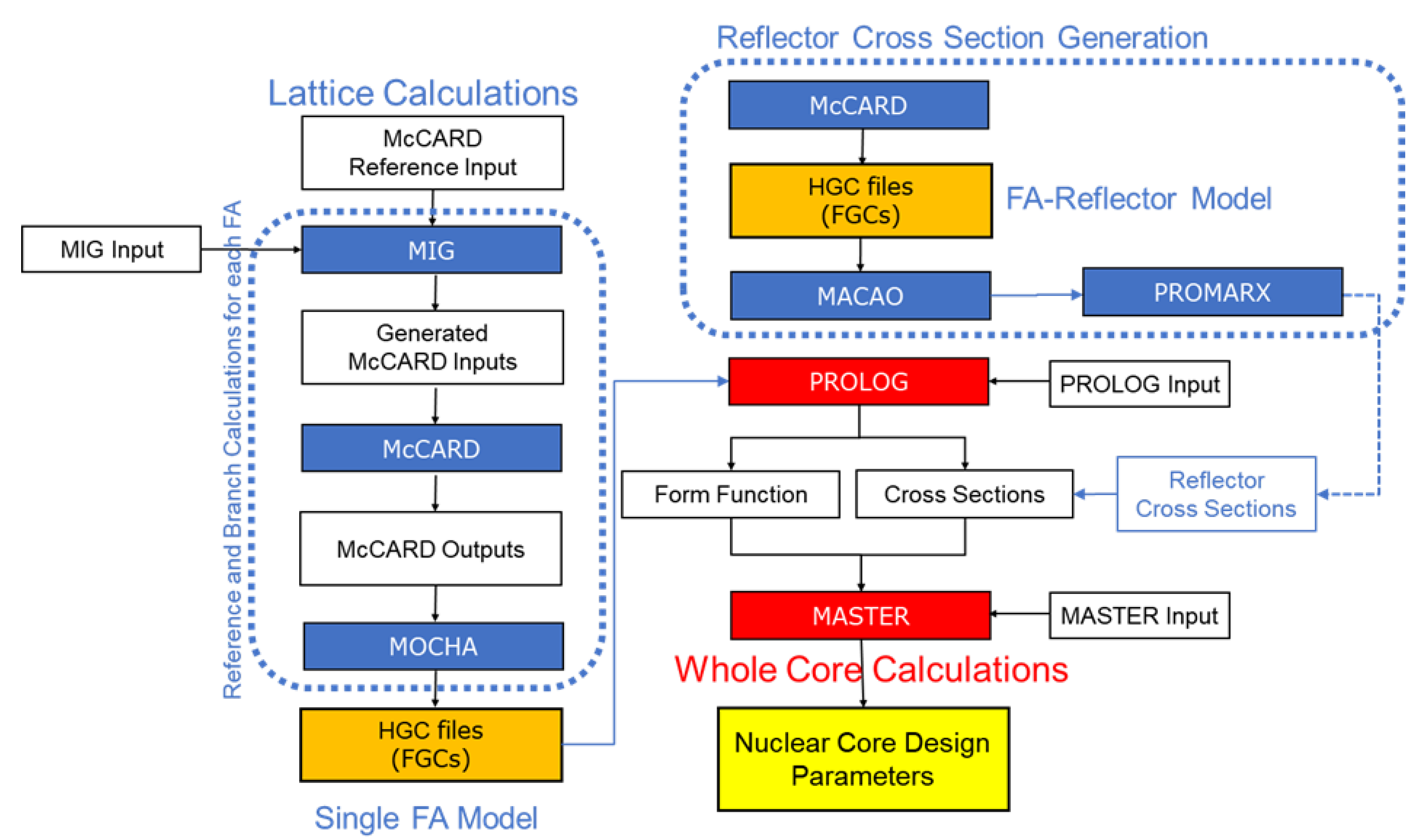
Figure 1 shows the flowchart of the existing McCARD/MASTER two-step code system for PWR core design analyses. The HGC-format FGC data include lattice-wise microscopic and macroscopic cross-sections, pin-wise power distributions, flux and burnup maps, average and surface fluxes, net currents, and other relevant design parameters. Because the FGC data change with various reactor operating conditions, such as soluble boron concentration (CSB), burnup (BU), fuel temperature (Tf), moderator temperature and density (ρm), and control rod position, they can be represented as a function of the corresponding conditions. A function for a microscopic cross-section can be expressed as follows:
σ ( B U , C S B , T f , ρ m ) = σ ( B U , C S B , 0 , T f , 0 , ρ m , 0 ) + σ C S B C S B C S B , 0 + σ T f T f T f , 0 + σ ρ m ρ m ρ m , 0 ,
where the subscript ‘0’ denotes the reference condition. For FGC generation, reference calculations are initially performed under reference conditions, followed by branch calculations under various conditions of each parameter at selected burnup points. The resulting FGC values obtained for the reference and each branch condition are then organized and stored in a tabulated format. In McCARD, the MC tallies (i.e., microscopic and macroscopic cross-sections, flux, current, and power distributions) can be easily calculated using the track-length estimation method. The MIG code automatically generates McCARD input files for the reference and branch calculations, and the MOCHA code converts and formats the FGCs generated from MC tallies into HGC-format files that can be read by the whole-core nodal analysis code (i.e., MASTER). This overall process follows the conventional two-step procedure used in deterministic code systems such as DeCART2D/MASTER, but the main difference is that the MC method is used in the lattice calculation, allowing for highly accurate group constants without homogenization and group condensation approximation. However, while it is necessary to generate reflector cross-sections for axial and radial reflector regions for whole-core analyses, the previous McCARD/MASTER two-step code system is not equipped with reflector cross-section generation code or procedures. Consequently, reflector cross-sections produced by the conventional deterministic-based DeCART2D/MASTER code system are used without modification.

2.2. Monte Carlo Reflector Cross-Section Generation

In a typical PWR core two-step analysis system, whole-core nodal code (e.g., MASTER) uses equivalent homogenized reflector cross-sections based on simplified equivalent theory. In a single FA case, an assembly discontinuity factor (ADF), which can be computed as the ratio of the heterogeneous surface flux to the homogeneous surface flux, is used as a DF (f) for equivalent cross-section generation, as below:
f g = ( Φ g ) s H E T ( Φ g ) s H O M ,
where ( Φ g ) s H E T and ( Φ g ) s H O M are the heterogeneous and homogeneous surface flux for the g-th energy group, respectively. However, in an FA-reflector model case for reflector cross-section generation, an additional homogeneous nodal solution is required, as the solution must incorporate the neutron reactions and leakage between the FA and reflector regions. In the DeCART2D/MASTER deterministic two-step code system, homogeneous nodal solutions are calculated via the SENM [12], a widely used method in rectangular node problems.
Figure 2 shows a homogenous problem and its boundary conditions, including the eigenvalue, homogenized cross-sections ( Σ g ¯ ), assembly averaged flux ( ϕ g ¯ ), surface currents ( J x , l m and J x , r m ), and transverse leakages ( T L x m , T L x m 1 , and T L x m + 1 ) of the current assembly (node m) and the neighbor assemblies (node m − 1 and node m + 1) for the SENM. The transverse leakage of node m can be defined as follows:
T L x m = J y , r m ¯ J y , l m ¯ h y ,
where hy is the y-axis width of node m. In general, a one-dimensional (1D) diffusion equation for a rectangular node can be expressed as follows:
D 2 x 2 ϕ ( x ) + Σ r ϕ ( x ) = q t ( x ) ,
where qt(x) is the total source term including fission and scattering, which is expanded by 4th-order Legendre polynomials. The 1D diffusion equation for the FA-reflector model can be solved using the SENM, which facilitates the determination of the unknown surface fluxes at each node in the homogeneous problem. Ultimately, the homogenous surface fluxes obtained from Equation (3) can be used to calculate the DF at the interface between the FA and reflector.
As shown in Figure 1, in the DeCART2D/MASTER deterministic design code system, HGC-format FGCs are calculated through DeCART2D-based two-dimensional (2D) core analysis and then converted by the PROMARX code [17] into effective cross-sections that can be used in the MASTER nodal calculations. In this procedure, PROMARX calculates the effective DF, effective reflector number density, and node-wise macroscopic transport cross-section by using the diffusion coefficients given in the HGC files. For whole-core nodal analysis, the reflector cross-sections are generated individually for axial and radial nodes.
In this study, a MC-based reflector cross-section generation system was established for the McCARD/MASTER two-step procedure. In the same manner as the method using DeCART2D and PROMARX, McCARD MC first calculates the boundary conditions (i.e., homogenized cross-sections, node average flux, and surface currents) to obtain homogenous solutions of the FA-reflector model shown in Figure 2. Here, external postprocessing code is needed in order to calculate DFs for nodal analyses via the SENM; thus, the Multi Assembly Cross-section and ADF Organizer (MACAO) code was developed as an external module for reflector cross-section generation based on MC tallies. Figure 3 shows the updated McCARD/MASTER two-step code system including the MC-based reflector cross-section generation procedure.
In the updated McCARD/MASTER code system, MACAO performs the FA-reflector nodal analyses via the SENM using the boundary conditions from the McCARD tallies. MACAO provides the DFs and macroscopic cross-sections to PROMARX, which, in turn, generates the effective cross-sections for the axial and radial reflector regions used in MASTER.

3. McCARD/MASTER Multi-Cycle Core Analyses for Hanbit Unit 3

3.1. Commercial PWR Hanbit Unit 3

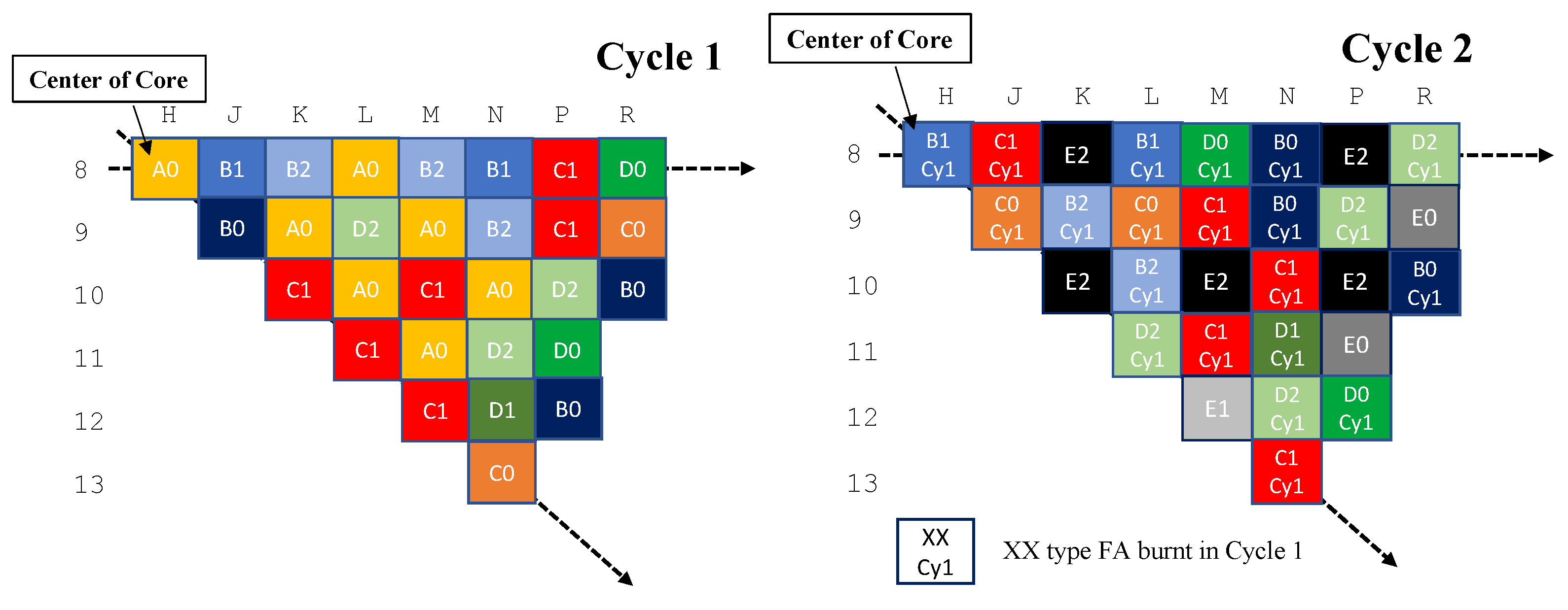
Hanbit Unit 3 is a commercial nuclear reactor of the OPR-1000 type located in the Republic of Korea. It has a thermal power of 3415 MWth, allowing it to generate 1000 MWe of electricity, and 177 FAs are loaded for each cycle. In this reactor, 16 × 16 Combustion Engineering (CE)-type FAs are loaded with 236 fuel rods with an active length of 381 cm, consisting of one instrument thimble and four control rod guide tubes. In this study, McCARD/MASTER two-step calculations for Hanbit Unit 3 were performed from cycle 1 to cycle 2; Figure 4 shows the corresponding FA loading pattern. In cycle 1, nine types of FAs (A0 through D2) are loaded. In cycle 2, all the FAs that were loaded in cycle 1 are reloaded, except A0, and three fresh FAs (i.e., E0, E1, and E2) are inserted into the core.
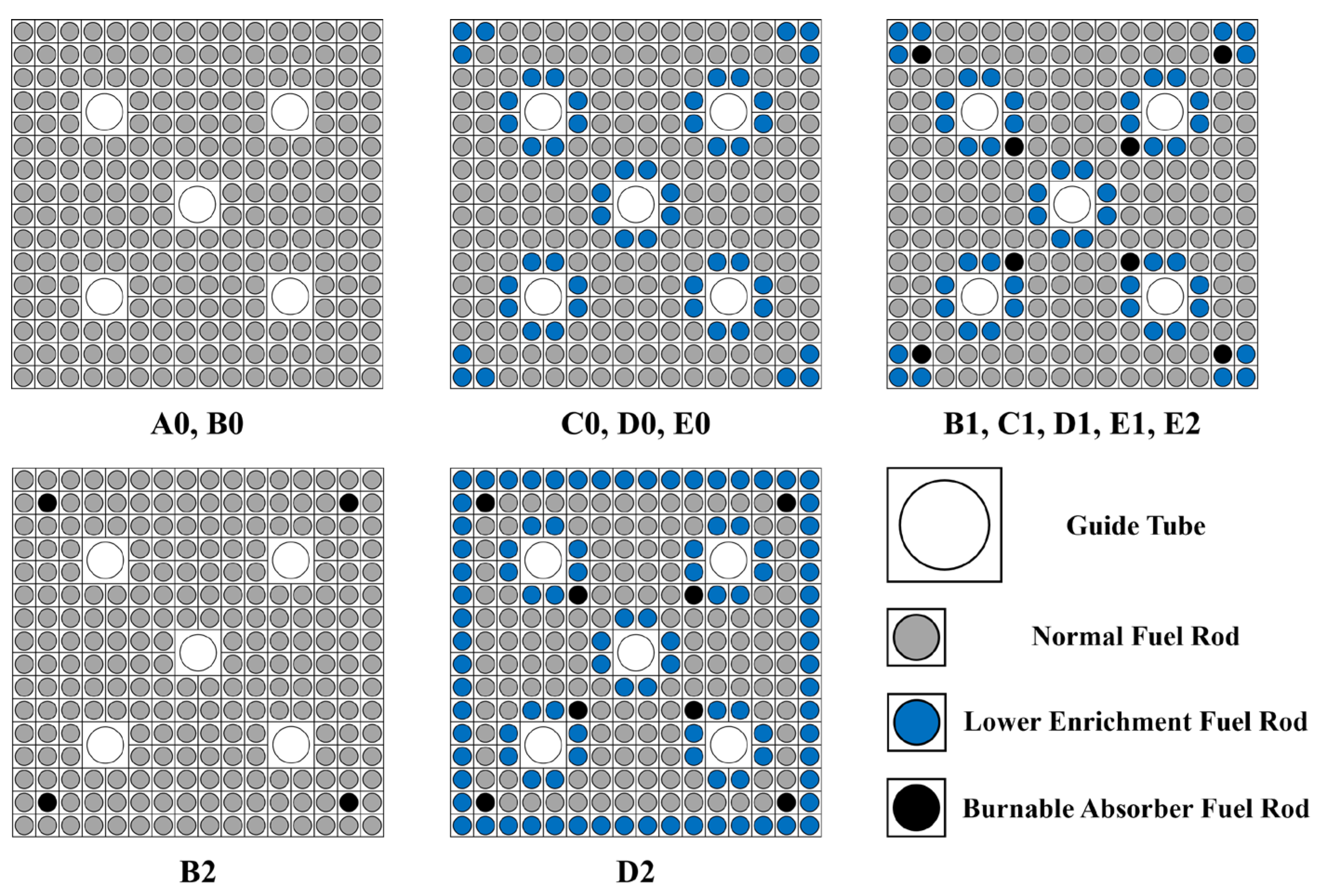
To perform whole-core analyses of cycles 1 and 2, FGCs must be prepared for all 12 types of FAs loaded over the two cycles. Meanwhile, it is important to note that burnable poison (BP) rods containing Gd2O3 and natural uranium have an axial cutback region in which BP is substituted with an alternative structural material. Accordingly, in the case of FAs with BP rods, it is necessary to generate two sets of FGCs: one for the axial region containing BP and another for the cutback region. In the case of Hanbit Unit 3, a total of 19 sets of FGCs must be generated using McCARD for whole-core analyses of cycles 1 and 2. Figure 5 and Table 1 show the specifications of the FAs loaded during the two cycles, while Figure 6 presents the axial cross-sections of the BP rods.

3.2. Few-Group Constant and Reflector Cross-Section Generation for Hanbit Unit 3

To conduct Hanbit Unit 3 whole-core analyses using the McCARD/MASTER two-step code system, FGCs and reflector cross-sections were generated. Table 2 shows the reactor operating conditions for the reference and branch calculations for FGC tabulation. For the reference calculations, the soluble boron concentration (CSB) and the fuel and moderator temperatures (Tf and Tm) were set to 500 ppm, 900 K, and 585 K, respectively. For the branch calculations, variation conditions of 700 K for the fuel temperature and 1000 ppm for the critical boron concentration (CBC) were applied, while the moderator temperature was varied under six conditions from 605 K to 295 K in order to cover the range from hot full power (HFP) to cold zero power (CZP). Figure 7 shows the setup of the burnup conditions used in both the reference and branch calculations. In the reference calculations, burnup analysis was performed at 62 burnup steps using a 0.5 MWd/kgU interval up to 20 MWd/kgU and a 1 MWd/kgU interval thereafter. In the branch calculations, 12 burnup steps were chosen from the 62 burnup steps in the reference calculations.
In this study, McCARD MC calculations were performed to generate FGCs with 10,000 histories per cycle and 100 active cycles for each FA. The MC code can easily and directly handle continuous-energy cross-sections without the need for the sophisticated cross-section library procedure used in lattice transport code. It also allows an explicit treatment of thermal scattering by incorporating the S(α,β) tables (e.g., hydrogen in H2O), which are implemented by overriding the corresponding cross-sections in the evaluated nuclear data. To fully exploit this advantage, FGCs were generated using both the ENDF/B-VII.1 and ENDF/B-VIII.0 evaluated nuclear data libraries. The ENDF/B-VIII.0 library, a successor to ENDF/B-VII.1, includes updated evaluations of major actinides (i.e., 235U, 238U, and 239Pu) and thermal scattering cross-sections. As such, this study enables an evaluation of the sensitivity of the whole-core analysis results, based on the use of the evaluated nuclear data libraries ENDF/B-VII.1 and ENDF/B-VIII.0. Table 3 compares the FGCs generated by DeCART2D and McCARD at the beginning of cycle (BOC) for the D0-type FA of Hanbit Unit 3. The FGCs of DeCART2D were calculated using the 47-group cross-section library of ENDF/B-VII.1. In the McCARD calculations, the uncertainties of the FGCs were estimated through 100 repeated calculations with different random seeds. Under the current neutron history conditions (i.e., 10,000 histories per cycle and 100 active cycles) for the McCARD calculations, the statistical uncertainties of the FGCs for the D1-type FA were less than 1.0%. Overall, the McCARD results are in good agreement with the DeCART2D results, within 1.0%. Table 4 compares the D0-type FA FGCs generated by McCARD between the ENDF/B-VII.1 and ENDF/B-VIII.0 libraries.
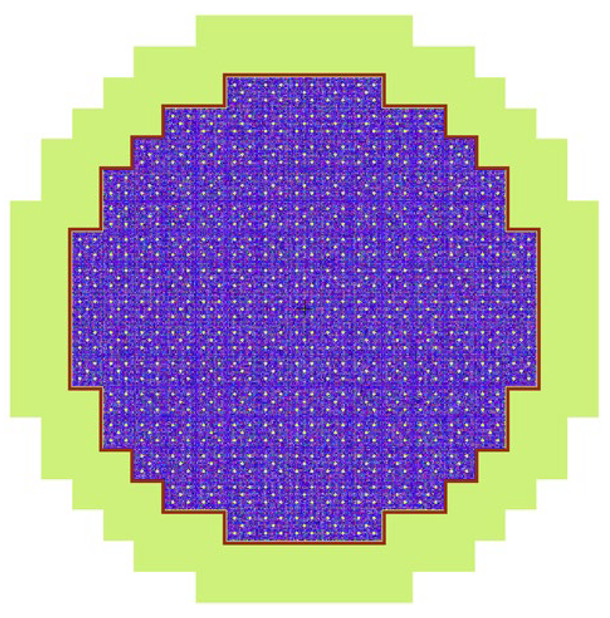
For the generation of radial reflector cross-sections for Hanbit Unit 3, a 2D core model, as shown in Figure 8, was considered in the same manner as with DeCART2D, and the DFs were obtained via SENM nodal calculations. In this model, the spacer grid smeared into the coolant, the baffle was explicitly considered, and the barrel was omitted. In the generation of axial reflector cross-sections, a 1D simplified axial model, as shown in Figure 9, was developed, and DFs were similarly generated.

3.3. Whole-Core Analyses for Hanbit Unit 3 Cycles 1 and 2

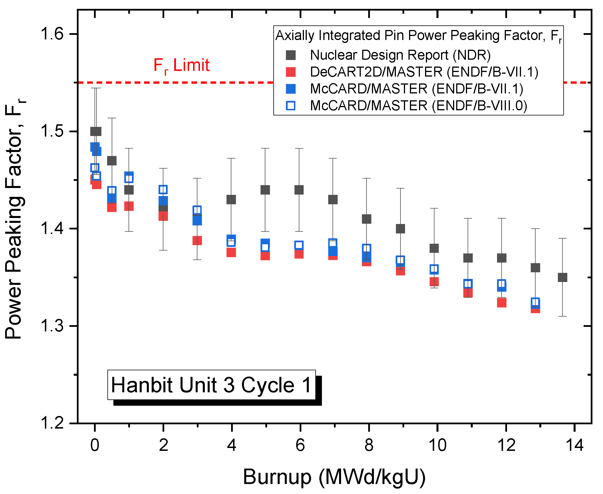
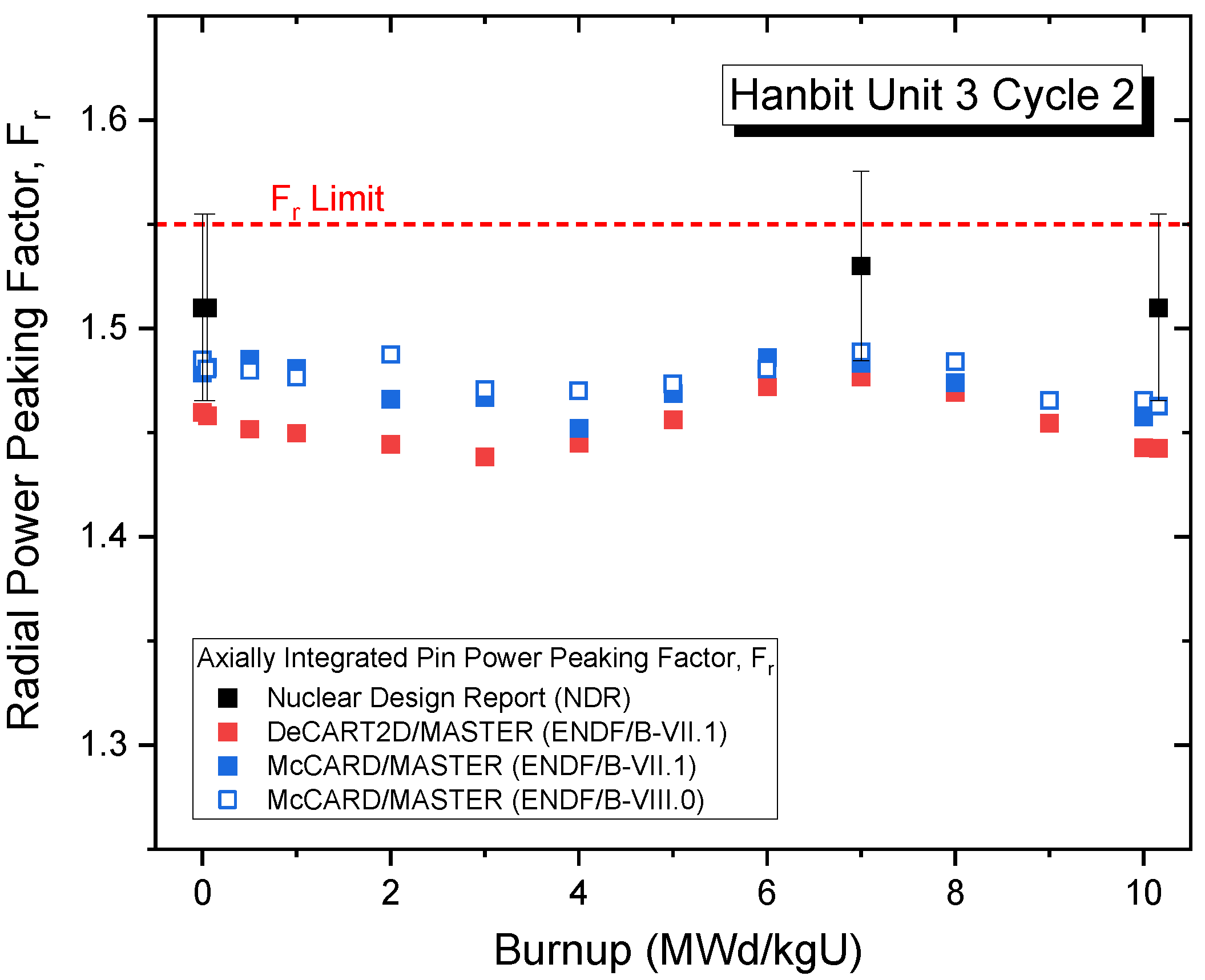
Whole-core analyses for Hanbit Unit 3 cycles 1 and 2 were conducted using the MASTER code with the FGCs and reflector cross-sections prepared by McCARD and MACAO/PROMARX, respectively. In the NDR, the uncertainties of the nuclear core design parameters were not directly provided. However, the uncertainties of the DIT/ROCS code system used for the NDR calculations were available in a document concerning another system (i.e., APR-1400) [18]. The reactivity uncertainties are within 0.26% Δρ, while the 95/95 confidence intervals for Fr and Fq are 5.93% and 4.24%, respectively. The NDR results for Hanbit Unit 3 are presented with error bars derived from the uncertainties reported in the document. The propagation of errors between McCARD and MASTER will be clarified and reported in a future study.

3.3.1. Critical Boron Concentrations for Hanbit Unit 3 Cycles 1 and 2

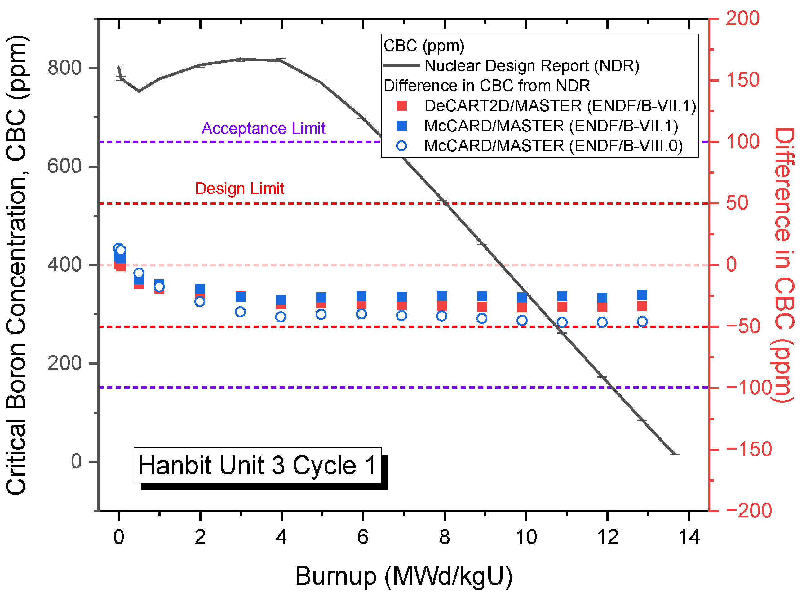
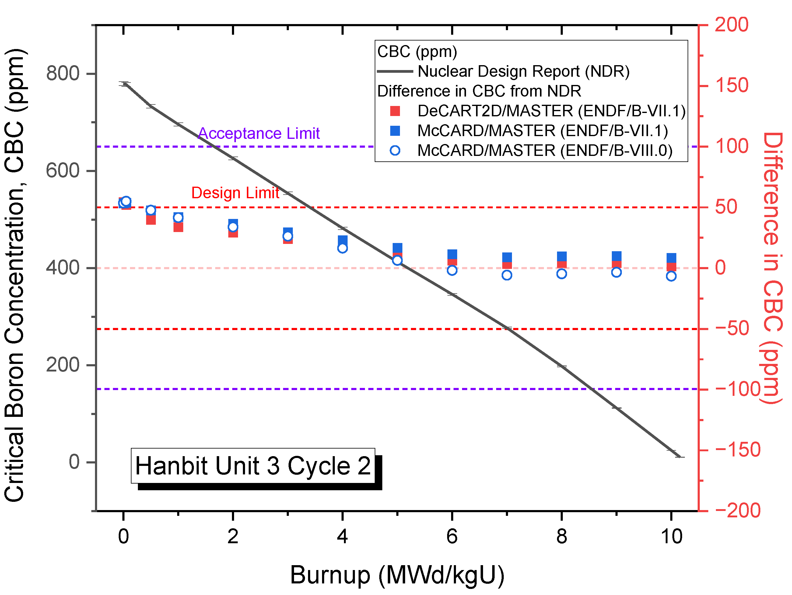
Figure 10 compares the CBCs of cycle 1 by the McCARD/MASTER and DeCART2D/MASTER two-step code systems as well as from the nuclear design report (NDR). The root mean square (RMS) difference in the CBC between the NDR and McCARD/MASTER with ENDF/B-VII.1 is 22.6 ppm, whereas that between the NDR and DeCART2D/MASTER is 28.0 ppm. The RMS difference in the cycle 1 CBC between the ENDF/B-VII.1 and ENDF/B-VIII.0 nuclear data libraries is 14 ppm. It was observed that the two-step code systems using the same evaluated nuclear data library reveal similar trends and differences in the CBC over burnup. Also, ENDF/B-VIII.0 appears to underestimate the CBC in comparison with ENDF/B-VII.1. One study [19] has reported that, in a typical PWR analysis, the use of ENDF/B-VIII.0 results in a more rapid decrease in reactivity over burnup, greater than that observed with ENDF/B-VII.1. Figure 11 compares the CBCs of Hanbit Unit 3 cycle 2 from the NDR and two-step code systems. The CBC behavior of each code system in cycle 2 shows a similar trend to that observed in cycle 1. Based on the NDR CBC results, the RMS differences for DeCART2D/MASTER and McCARD/MASTER using the ENDF/B-VII.1 library are 23.4 ppm and 31.9 ppm, respectively. It is well known that the design criteria for the CBC are within 50 ppm for start-up and normal operation in typical PWRs. Evidently, all the CBC results herein meet the design criteria well, except for cycle 2 BOC. Notably, the statistical uncertainties of the McCARD/MASTER code are not presented in this study because the statistical errors of the McCARD FGCs listed in Table 3 are very small, and, consequently, the uncertainties propagated in the MASTER results were anticipated to be insignificant.

3.3.2. Power Distributions and Power-Peaking Factors for Hanbit Unit 3 Cycles 1 and 2

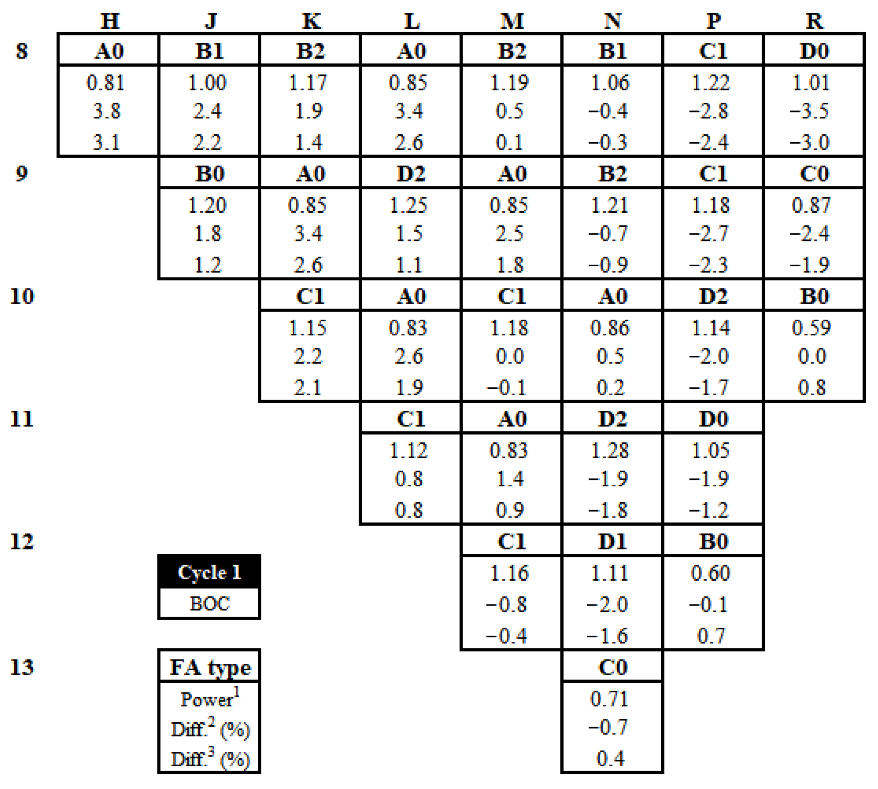
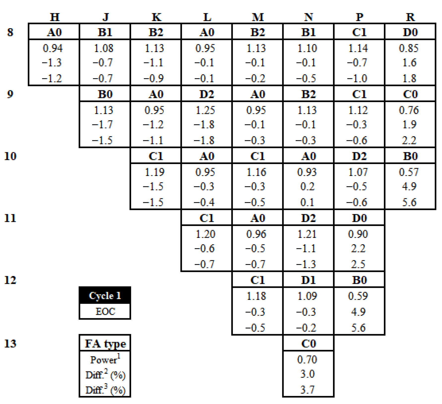
Figure 12, Figure 13 and Figure 14 compare normalized FA-wise power distributions among the McCARD/MASTER, DeCART2D/MASTER, and NDR results at various burnup points. In the McCARD/MASTER and DeCART2D/MASTER calculations, the ENDF/B-VII.1 evaluated nuclear data library was used. For each FA position, the first line in the figures indicates the FA batch identification (ID), and the second line shows the normalized FA-wise power distribution calculated by McCARD/MASTER. The third and fourth lines present the differences in the normalized FA-wise power distribution between McCARD/MASTER and the NDR and between McCARD/MASTER and DeCART2D/MASTER, respectively. In particular, Figure 12 and Figure 13 show the FA-wise power distributions near the BOC and the end of the cycle (EOC) for Hanbit Unit 3 cycle 1. For the BOC for cycle 1, with reference to the NDR results, the RMS differences for McCARD/MASTER and DeCART2D/MASTER are 2.02% and 1.65%, respectively.
Meanwhile, at the EOC for cycle 1, the RMS differences are 1.31% for McCARD/MASTER and 1.46% for DeCART2D/MASTER. Figure 14 shows the FA-wise power distributions near the BOC for Hanbit Unit 3 cycle 2. In this case, the RMS differences at the BOC for cycle 2, based on the NDR results, are 1.16% for McCARD/MASTER and 1.08% for DeCART2D/MASTER. Figure 15 compares the 1D axial-normalized power distributions determined by McCARD/MASTER and DeCART2D/MASTER for the BOC for cycle 1. The RMS difference between the two-step code systems is about 0.25%. The results of these comparisons of FA-wise and 1D axial power distributions confirm that the new reflector cross-section generation system with the SENM-based MACAO code was properly implemented in the McCARD/MASTER code system.
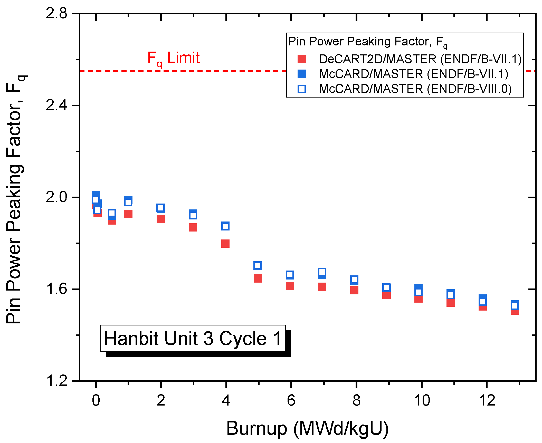
In nuclear core design analyses, Fq and Fr refer to power-peaking factors in fuel rods. They are specifically utilized in nuclear reactor safety assessments and in setting power operation limits. Figure 16 and Figure 17 present the axially integrated pin power peaking factors Fr for cycles 1 and 2, respectively. The results confirm that all the Fr values meet the design limit of 1.55 over cycles 1 and 2. Figure 18 and Figure 19 show the 3D-node pin power peaking factors Fq for cycles 1 and 2, respectively. Similarly, all the calculation results show that the Fq values remain within the design limit of 2.6 throughout the entirety of cycles 1 and 2.

3.3.3. Temperature Coefficients for Hanbit Unit 3 Cycles 1 and 2

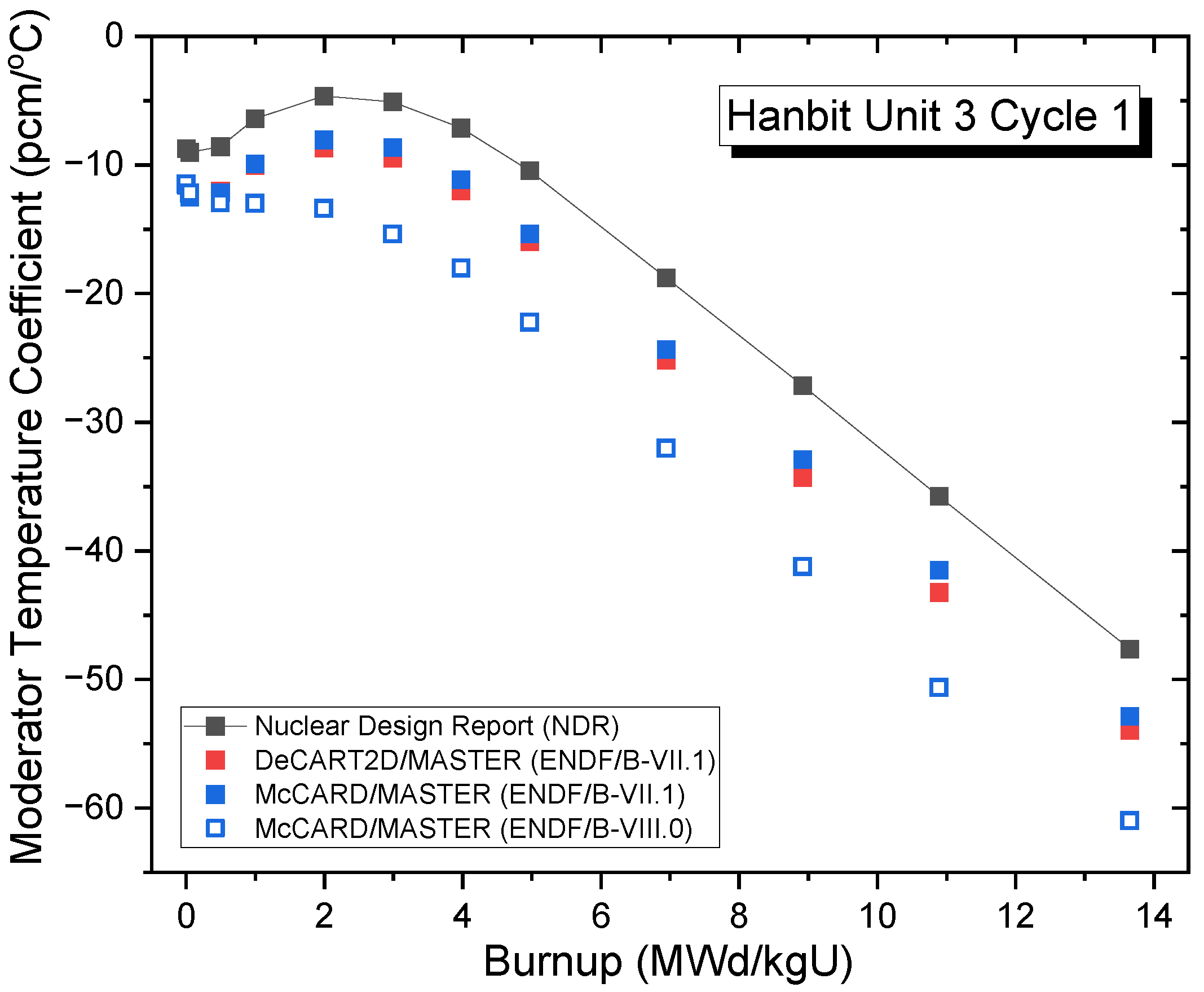
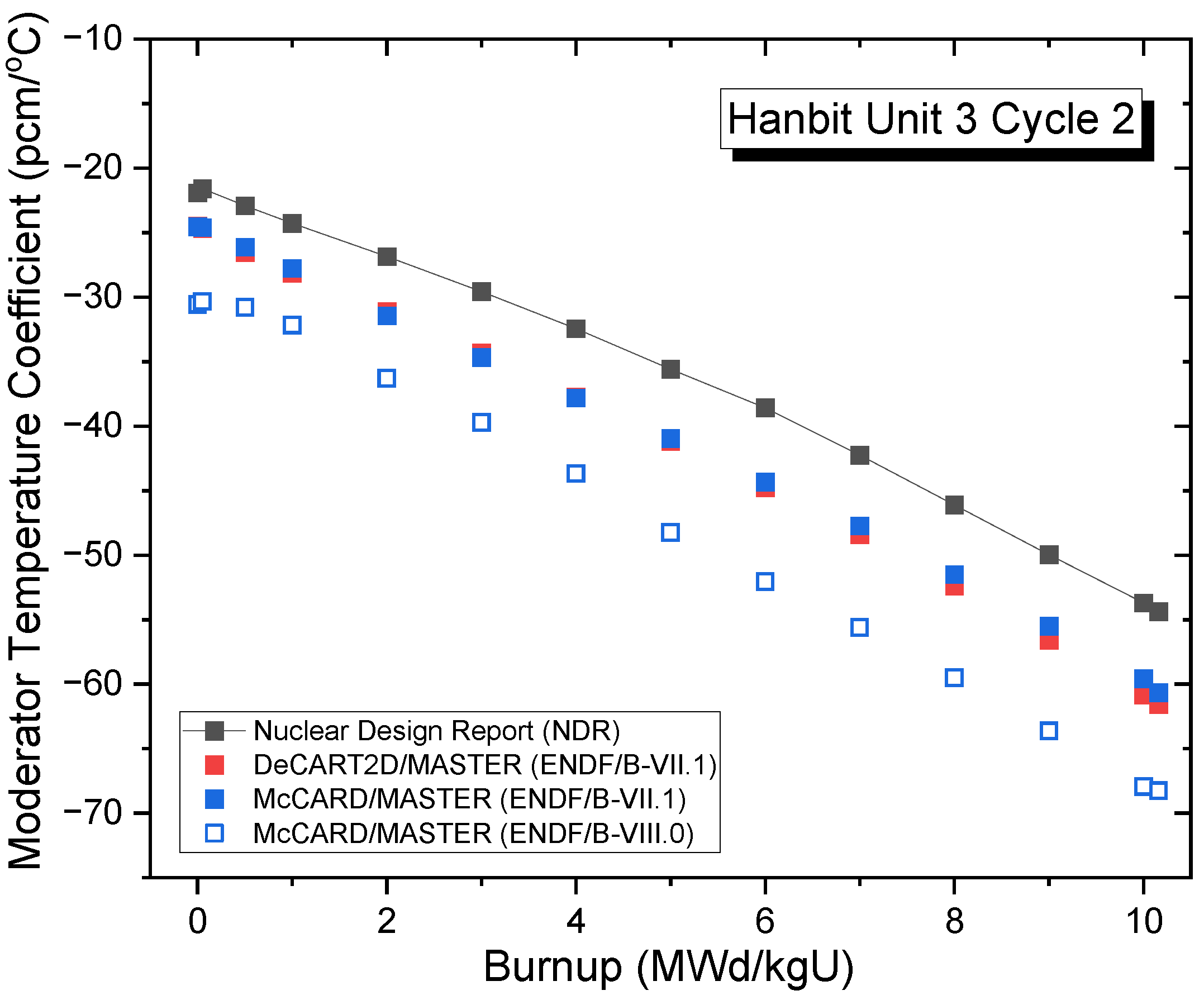
Figure 20 and Figure 21 compare the moderator temperature coefficients (MTCs) for Hanbit Unit 3 cycles 1 and 2, respectively. In general, the MTC should be negative to ensure the inherent safety of the reactor. As the core depletes, the MTC tends to become more negative because of the reduction in the CBC. To prevent difficulties in power control caused by an excessively negative MTC, reactor cores are typically designed to maintain the MTC within the range of 0 to −80 pcm/°C. In the McCARD/MASTER calculations conducted with ENDF/B-VII.1, the MTCs range from −11.5 to −68.3 pcm/°C and are, on average, 4.30 pcm/°C lower than those in the NDR and similar to the DeCART2D/MASTER results obtained using the same evaluated nuclear data library. Meanwhile, McCARD/MASTER with ENDF/B-VIII.0 yielded MTC values about 6 pcm/°C lower than those obtained with ENDF/B-VII.1.
Lastly, Table 5 shows the fuel temperature coefficients (FTCs) for Hanbit Unit 3 cycles 1 and 2. The maximum difference between the McCARD/MASTER results and the NDR is 0.35 pcm/°C, while the difference from DeCART2D/MASTER is 0.18 pcm/°C. The MTC and FTC results, obtained using the same ENDF/B-VII.1 library, were in good agreement between the McCARD/MASTER and DeCART2D/MASTER analyses.

4. Conclusions

In this study, the Monte Carlo-based reflector cross-section generation code MACAO was developed to complete the McCARD/MASTER two-step core analysis procedure. MACAO can generate the DFs needed for whole-core nodal analyses using the SENM. By incorporating the newly developed reflector cross-section generation system, a fully MC-based two-step analysis code system was established without relying on conventional deterministic codes. To examine the updated McCARD/MASTER two-step analysis code system, consecutive multi-cycle core follow calculations were performed for cycles 1 and 2 of the commercial PWR Hanbit Unit 3. The validity of nuclear core design parameters (i.e., CBC, power distribution, pin power peaking factors, and MTC and FTC) was assessed through comparison with the conventional deterministic DeCART2D/MASTER two-step analysis results and the NDR. Overall, the McCARD/MASTER results were in good agreement with those obtained from DeCART2D/MASTER and the NDR. Moreover, all the results met the design criteria for commercial PWRs (i.e., ΔCBC within 50 ppm, Fr ≤ 1.55, Fq ≤ 2.6 over cycles 1 and 2, and MTC values ≤ 6 pcm/°C), except for CBC at the BOC for cycle 2. Although the CBC at the BOC for cycle 2 slightly exceeded the design criteria, it remained within the acceptance criteria (i.e., ≤1000 pcm) [20] for a typical commercial PWR, confirming the validity of the McCARD/MASTER results.
In the near future, the McCARD FGC and reflector cross-section generation system will be extended to heterogeneous nuclear core systems, such as very-high-temperature gas-cooled reactors (VHTRs) and sodium-cooled fast reactors (SFRs), which require detailed resonance treatment to fully exploit the strengths of the MC method. To support this endeavor, the reflector cross-section generation approach will be extended to include a triangle-based polynomial expansion nodal method for calculating the DFs of hexagonal lattices. This approach will be validated against established international benchmarks (e.g., the OECD/NEA VHTR and SFR exercises) to demonstrate its accuracy and suitability for advanced reactor analysis.

Author Contributions

Conceptualization, H.J.P.; methodology, H.J.P.; software, J.W.P.; validation, J.W.P.; formal analysis, J.W.P.; investigation, J.W.P.; resources, J.W.P.; data curation, J.W.P.; writing—original draft preparation, J.W.P.; writing—review and editing, H.J.P.; visualization, H.J.P. and J.W.P.; supervision, H.J.P.; project administration, H.J.P.; funding acquisition, H.J.P. All authors have read and agreed to the published version of the manuscript.

Funding

This work was supported by a Human Resources Development grant from the Korea Institute of Energy Technology Evaluation and Planning (KETEP)—funded by the Ministry of Trade, Industry, and Energy of Korea (No. RS-2024-00401705)—and by a National Research Foundation of Korea (NRF) grant funded by the Korean government (Ministry of Science and ICT) (No. RS-2025-13222972).

Data Availability Statement

The original contributions presented in the study are included in the article, further inquiries can be directed to the corresponding author.

Conflicts of Interest

The authors declare no conflicts of interest. The funders had no role in the design of the study; in the collection, analyses, or interpretation of data; in the writing of the manuscript; or in the decision to publish the results.

Abbreviations

The following abbreviations are used in this manuscript:
ADFAssembly discontinuity factor
BOCBeginning of the cycle
BPBurnable poison
CBCCritical boron concentration
CECombustion engineering
CZPCold zero power
DFDiscontinuity factor
EOCEnd of cycle
FAFuel assembly
FGCFew-group constant
FTCFuel temperature coefficient
HFPHot full power
MACAOMulti-assembly cross-section and ADF organizer
MCMonte Carlo
MTCModerator temperature coefficient
NDRNuclear design report
PWRPressurized water reactor
RMSRoot mean square
SENMSource expansion nodal method

References

  1. Smith, K.S. Assembly Homogenization Techniques for Light Water Reactor Analysis. Prog. Nucl. Energy 1986, 17, 303–335. [Google Scholar] [CrossRef]
  2. Redmond, E.L., II. Multi-Group Cross Section Generation via Monte Carlo Method. Ph.D. Thesis, Massachusetts Institute of Technology, Cambridge, MA, USA, 1997. [Google Scholar]
  3. Shim, H.J.; Cho, J.Y.; Song, J.S.; Kim, C.H. Generation of Few Group Diffusion Theory Constants by Monte Carlo Code. Trans. Am. Nucl. Soc. 2008, 99, 343. [Google Scholar]
  4. Park, H.J.; Shim, H.J.; Joo, H.G.; Kim, C.H. Generation of Few-Group Diffusion Theory Constants by Monte Carlo Code McCARD. Nucl. Sci. Eng. 2012, 172, 66–77. [Google Scholar] [CrossRef]
  5. Fridman, E.; Leppanen, J. On the Use of the Serpent Monte Carlo Code for Few-Group Cross Section Generation. Ann. Nucl. Energy 2010, 38, 1399–1405. [Google Scholar] [CrossRef]
  6. Yoo, S.Y.; Shim, H.J.; Kim, C.H. Monte Carlo Few-Group Constant Generation for CANDU 6 Core Analysis. Sci. Technol. Nucl. Install. 2015, 2015, 284642. [Google Scholar] [CrossRef]
  7. Nguyen, T.D.C.; Lee, H.; Lee, D. Use of Monte Carlo code MCS for multigroup cross section generation for fast reactor analysis. Nucl. Eng. Technol. 2021, 53, 2788–2802. [Google Scholar] [CrossRef]
  8. Shim, H.J.; Han, B.S.; Jung, J.S.; Park, H.J.; Kim, C.H. McCARD: Monte Carlo Code for Advanced Reactor Design and Analysis. Nucl. Eng. Technol. 2012, 44, 161–176. [Google Scholar] [CrossRef]
  9. Park, H.J.; Shim, H.J.; Joo, H.G.; Kim, C.H. Uncertainty quantification of few-group Diffusion Theory Constants Generated by the B1 Theory-Augmented Monte Carlo Method. Nucl. Sci. Eng. 2013, 175, 28–43. [Google Scholar] [CrossRef]
  10. Wu, Y.; Song, Q.; Feng, K.; Vidal, J.F.; Gu, H.; Guo, H. Multigroup cross-sections generated using Monte-Carlo method with flux-moment homogenization technique for fast reactor analysis. Nucl. Eng. Technol. 2023, 55, 2474–2482. [Google Scholar] [CrossRef]
  11. Li, J.; Seker, V.; Ward, A.; Downar, T. Uncertainty Propagation of Monte Carlo Cross-Section Generation for Graphite-Moderated Pebble Bed Reactors. Nucl. Sci. Eng. 2025, 199, 772–792. [Google Scholar] [CrossRef]
  12. Yoon, J.I.; Joo, H.G. Two-Level Coarse Mesh Finite Difference Formulation with Multigroup Source Expansion Nodal Kernels. J. Nucl. Sci. Technol. 2008, 45, 668–682. [Google Scholar] [PubMed]
  13. Cho, J.Y.; Shim, C.; Han, T.Y.; Lee, K.; Lee, C.; Song, J.S.; Park, S.Y.; Park, H.J.; Jeong, H.J.; Jo, C.K.; et al. DeCART2D v1.1 User’s Manual; KAERI/UM-40/2016; Korea Atomic Energy Research Institute: Daejeon, Republic of Korea, 2016. [Google Scholar]
  14. Zee, S.Q.; Lee, C.G.; Lee, C.C.; Song, J.S.; Kim, S.J.; Kim, H.Y.; Lim, C.J.; Yoo, C.S.; Baek, B.C.; Yoo, H.S.; et al. Nuclear Design Report for Yonggwang Unit 3 Cycle 1; KAERI/TR-542/95; Korea Atomic Energy Research Institute: Daejeon, Republic of Korea, 1995. [Google Scholar]
  15. Yoo, C.S.; Ryu, H.S.; Baek, B.C.; Park, J.H.; Cho, Y.C.; Park, S.Y.; Song, J.S. Nuclear Design Report for Yonggwang Unit 3 Cycle 2; KAERI/TR-605/96; Korea Atomic Energy Research Institute: Daejeon, Republic of Korea, 1996. [Google Scholar]
  16. Cho, J.Y.; Jeong, H.J.; Song, J.S.; Park, S.Y.; Lee, K.; Lee, C.; Shim, C.; Park, H.J.; Choi, Y.; Koo, B.S. MASTER v4.0 User’s Manual; KAERI/UM-41/2016; Korea Atomic Energy Research Institute: Daejeon, Republic of Korea, 2016. [Google Scholar]
  17. Shim, C.B.; Lee, K.H.; Cho, J.Y. Improvement of Axial Reflector Cross Section Generation Model for PWR Core Analysis. In Proceedings of the Transactions of the Korean Nuclear Society Autumn Meeting, Gyeongju, Republic of Korea, 27–28 October 2016. [Google Scholar]
  18. APR-1400 Design Control Document Tier 2; APR1400-K-X-FS-14002-NP. Korea Electric Power Corporation: Naju-si, Republic of Korea; Korea Hydro & Nuclear Power Co., Ltd.: Gyeongju-si, Republic of Korea, 2018.
  19. Park, H.J.; Kang, H.; Lee, H.C.; Cho, J.Y. Comparison of ENDF/B-VIII.0 and ENDF/B-VII.1 in Criticality, Depletion Benchmark, and Uncertainty Analyses by McCARD. Ann. Nucl. Energy 2019, 131, 443–459. [Google Scholar]
  20. Cabellos, O.; Castro, E.; Ahnert, C.; Holgado, C. Propagation of Nuclear Data Uncertainties for PWR Core Analysis. Nucl. Eng. Technol. 2014, 46, 299–312. [Google Scholar] [CrossRef]
Figure 1. Flowchart of the existing McCARD/MASTER two-step code system for a pressurized water reactor (PWR) core design.
Energies 18 05065 g001
Figure 2. Problem concerning the calculation of discontinuity factors (DFs).
Energies 18 05065 g002
Figure 3. New McCARD/MASTER two-step code system with a Monte Carlo–based reflector cross-section generation procedure.
Energies 18 05065 g003
Figure 4. Fuel assembly (FA) loading pattern in cycles 1 and 2 of Hanbit Unit 3.
Energies 18 05065 g004
Figure 5. Radial cross-sections of the FAs loaded in cycles 1 and 2.
Energies 18 05065 g005
Figure 6. Axial cross-section of a Hanbit Unit 3 FA loaded with burnable poison (BP) rods.
Energies 18 05065 g006
Figure 7. Burnup steps for the reference and branch calculations.
Energies 18 05065 g007
Figure 8. Two-dimensional core model for McCARD radial reflector cross-section generation.
Energies 18 05065 g008
Figure 9. Simplified 1D model for axial reflector cross-section generation.
Energies 18 05065 g009
Figure 10. Comparison of critical boron concentrations (CBCs) for Hanbit Unit 3 cycle 1 using ENDF/B-VII.1 and ENDF/B-VIII.0.
Energies 18 05065 g010
Figure 11. Comparison of CBCs for Hanbit Unit 3 cycle 2 using ENDF/B-VII.1 and ENDF/B-VIII.0.
Energies 18 05065 g011
Figure 12. Comparison of FA-wise power distributions at the beginning of the cycle (BOC) for Hanbit Unit 3 cycle 1 using ENDF/B-VII.1. 1 Normalized FA-wise power distribution determined by McCARD/MASTER. 2 Difference (%) between McCARD/MASTER and NDR. 3 Difference (%) between McCARD/MASTER and DeCART2D/MASTER.
Energies 18 05065 g012
Figure 13. Comparison of FA-wise power distributions at the end of the cycle (EOC) for Hanbit Unit 3 cycle 1 using ENDF/B-VII.1. 1 Normalized FA-wise power distribution determined by McCARD/MASTER. 2 Difference (%) between McCARD/MASTER and NDR. 3 Difference (%) between McCARD/MASTER and DeCART2D/MASTER.
Energies 18 05065 g013
Figure 14. Comparison of FA-wise power distributions at the BOC for Hanbit Unit 3 cycle 2 using ENDF/B-VII.1. 1 Normalized FA-wise power distribution determined by McCARD/MASTER. 2 Difference (%) between McCARD/MASTER and NDR. 3 Difference (%) between McCARD/MASTER and DeCART2D/MASTER.
Energies 18 05065 g014
Figure 15. Comparison of 1D axial power distributions between DeCART2D/MASTER and McCARD/MASTER at the BOC for Hanbit Unit 3 cycle 1 using ENDF/B-VII.1.
Energies 18 05065 g015
Figure 16. Comparison of the values of radial pin power peaking factor Fr for Hanbit Unit 3 cycle 1 using ENDF/B-VII.1 and ENDF/B-VIII.0.
Energies 18 05065 g016
Figure 17. Comparison of the values of the radial pin power peaking factor Fr for Hanbit Unit 3 cycle 2 using ENDF/B-VII.1 and ENDF/B-VIII.0.
Energies 18 05065 g017
Figure 18. Comparison of the values of the pin power peaking factor Fq for Hanbit Unit 3 cycle 1 using ENDF/B-VII.1 and ENDF/B-VIII.0.
Energies 18 05065 g018
Figure 19. Comparison of the pin power peaking factor Fq values for Hanbit Unit 3 cycle 2 using ENDF/B-VII.1 and ENDF/B-VIII.0.
Energies 18 05065 g019
Figure 20. Comparison of moderator temperature coefficients for Hanbit Unit 3 cycle 1 using ENDF/B-VII.1 and ENDF/B-VIII.0.
Energies 18 05065 g020
Figure 21. Comparison of moderator temperature coefficients for Hanbit Unit 3 cycle 2 using ENDF/B-VII.1 and ENDF/B-VIII.0.
Energies 18 05065 g021
Table 1. Specifications of the FAs during cycles 1 and 2.
FA TypeU-235 Enrichment (w/o)Number of Fuel RodsNumber of BA 1 RodsBA Content (w/o)
Normal Fuel RodLower-Enrichment Fuel RodNormal Fuel RodLower-Enrichment Fuel Rod
A01.323600
B02.323600
B12.31.31765284.0
B22.3232044.0
C02.82.3184520
C12.82.31765284.0
D03.32.8184520
D13.32.81765284.0
D23.32.812810084.0
E04.03.6184520
E14.03.61765286.0
E23.63.11765286.0
1 BA: Burnable absorber.
Table 2. Reactor operating conditions for the reference and branch calculations.
ParameterUnitVariation Conditions
Reference CalculationBranch Calculation
Boron Concentration (CSB)ppm5001000
Fuel Temperature (Tf)K900700
Moderator Temperature (Tm)K585605, 565, 535, 485, 405, 295
Table 3. Comparison of the D0-type FA FGCs between McCARD and DeCART2D with the ENDF/B-VII.1 library.
ParameterCross-SectionDifference
Rate
(%)
McCARD
(Barn)
Rel. SD 1 (%)DeCART2D
(Barn)
Buckling B 2 4.419 × 10−30.1384.433 × 10−3−0.329
Group 1 (Fast) D 1 1.430 × 1000.0211.429 × 1000.409
Σ a , 1 8.529 × 10−30.0848.558 × 10−3−0.336
ν Σ f , 1 5.859 × 10−30.0675.857 × 10−30.062
Group 2
(Thermal)
D 2 4.797 × 10−10.0234.830 × 10−1−0.682
Σ a , 2 7.117 × 10−20.0337.185 × 10−2−0.942
ν Σ f , 2 1.128 × 10−10.0421.137 × 10−1−0.832
Scattering Matrix Σ s , 1 1 4.827 × 10−10.0134.844 × 10−1−0.339
Σ s , 1 2 1.674 × 10−20.0391.682 × 10−2−0.512
Σ s , 2 1 2.144 × 10−40.9862.124 × 10−40.956
Σ s , 2 2 1.135 × 1000.0211.129 × 1000.458
1 Relative standard deviation of McCARD.
Table 4. Comparison of the D0-type FA FGCs calculated by McCARD using ENDF/B-VII.1 and ENDF/B-VIII.0.
DataENDF/B-VII.1ENDF/B-VIII.0Difference
(%)
Cross-Section (Barn)Rel. SD 1 (%)Cross-Section (Barn)Rel. SD 1 (%)
Buckling B 2 4.419 × 10−30.1384.416 × 10−30.158−0.067
Group 1
(Fast)
D 1 1.430 × 1000.0211.429 × 1000.020−0.065
Σ a , 1 8.529 × 10−30.0848.578 × 10−30.0960.564
ν Σ f , 1 5.859 × 10−30.0675.867 × 10−30.0600.106
Group 2
(Thermal)
D 2 4.797 × 10−10.0234.885 × 10−10.0221.824
Σ a , 2 7.117 × 10−20.0337.243 × 10−20.0341.773
ν Σ f , 2 1.128 × 10−10.0421.146 × 10−10.0431.616
Scattering
Matrix
Σ s , 1 1 4.827 × 10−10.0134.837 × 10−10.0110.194
Σ s , 1 2 1.674 × 10−20.0391.685 × 10−20.0440.677
Σ s , 2 1 2.144 × 10−40.9862.200 × 10−41.1602.614
Σ s , 2 2 1.135× 1000.0211.118× 1000.019−1.158
1 Relative standard deviation of McCARD.
Table 5. Comparison of fuel temperature coefficients.
CaseFuel Temperature Coefficient (pcm/°C)
NDRDeCART2D/MASTERMcCARD/MASTER
ENDF/B-VII.1ENDF/B-VII.1ENDF/B-VIII.0
Cycle 1BOC−2.82−2.54−2.42−2.40
EOC−2.90−2.47−2.64−2.67
Cycle 2BOC−2.75−2.43−2.40−2.67
EOC−2.90−2.61−2.79−2.88
Disclaimer/Publisher’s Note: The statements, opinions and data contained in all publications are solely those of the individual author(s) and contributor(s) and not of MDPI and/or the editor(s). MDPI and/or the editor(s) disclaim responsibility for any injury to people or property resulting from any ideas, methods, instructions or products referred to in the content.