Review

A Comprehensive Review of Well Integrity Challenges and Digital Twin Applications Across Conventional, Unconventional, and Storage Wells

by
Ahmed Ali Shanshool Alsubaih
1,*,
Kamy Sepehrnoori
1,
Mojdeh Delshad
1,* and
Ahmed Alsaedi
2
1
Hildebrand Department of Petroleum and Geosystems Engineering, The University of Texas at Austin, Austin, TX 78712, USA
2
SLB, Basra 61001, Iraq
*
Authors to whom correspondence should be addressed.
Energies 2025, 18(17), 4757; https://doi.org/10.3390/en18174757
Submission received: 10 July 2025 / Revised: 6 August 2025 / Accepted: 2 September 2025 / Published: 6 September 2025

Abstract

Well integrity is paramount for the safe, environmentally responsible, and economically viable operation of wells throughout their lifecycle, encompassing conventional oil and gas production, unconventional resource extraction (e.g., shale gas and tight oil), and geological storage applications (CO2, H2, and natural gas). This review presents a comprehensive synthesis of well integrity challenges, failure mechanisms, monitoring technologies, and management strategies across these operational domains. Key integrity threats—including cement sheath degradation (chemical attack, debonding, cracking, microannuli), casing failures (corrosion, collapse, burst, buckling, fatigue, wear, and connection damage), sustained casing pressure (SCP), and wellhead leaks—are examined in detail. Unique challenges posed by hydraulic fracturing in unconventional wells and emerging risks in CO2 and hydrogen storage, such as corrosion, carbonation, embrittlement, hydrogen-induced cracking (HIC), and microbial degradation, are also highlighted. The review further explores the evolution of integrity standards (NORSOK, API, ISO), the implementation of Well Integrity Management Systems (WIMS), and the integration of advanced monitoring technologies such as fiber optics, logging tools, and real-time pressure sensing. Particular emphasis is placed on the role of digital technologies—including artificial intelligence, machine learning, and digital twin systems—in enabling predictive maintenance, early failure detection, and lifecycle risk management. The novelty of this review lies in its integrated, cross-domain perspective and its emphasis on digital twin applications for continuous, adaptive well integrity surveillance. It identifies critical knowledge gaps in modeling, materials qualification, and data integration—especially in the context of long-term CO2 and H2 storage—and advocates for a proactive, digitally enabled approach to lifecycle well integrity.

1. Introduction

Well integrity, fundamentally defined as the application of technical, operational, and organizational solutions to mitigate the risk of uncontrolled fluid release throughout a well’s life, stands as a cornerstone for safety, environmental protection, and economic efficiency in the energy sector [1,2]. Its scope extends from traditional oil and gas production in conventional reservoirs to the complex operations in unconventional formations and the burgeoning field of geological storage for carbon dioxide (CO2), hydrogen (H2), and methane (CH4) [3,4]. Maintaining containment is not merely an operational goal but a critical necessity to prevent catastrophic blowouts, subsurface contamination of groundwater aquifers, surface leaks, greenhouse gas emissions, or significant operational and financial losses [5,6]. This challenge is profoundly time-dependent; barriers that are intact upon well completion can degrade over time due to the relentless influence of evolving subsurface and operational conditions [7,8].
Throughout its operational life, a well’s primary and secondary barrier systems—including casing, tubing, cement sheaths, packers, seals, and wellhead components—are subjected to a barrage of stressors. These include dynamic pressure fluctuations, cyclic temperature changes associated with production and injection, exposure to potentially corrosive formation fluids (containing CO2, H2S, brines, and organic acids), geomechanical stresses arising from reservoir depletion or pressurization, and mechanical wear from interventions or flow [9,10,11]. These factors can initiate and propagate damage mechanisms such as debonding at interfaces (casing-cement, cement-formation), cracking within the brittle cement matrix, chemical degradation of cement and elastomers, and corrosion or mechanical failure of steel tubular [12,13]. Indeed, many significant oil and gas incidents are directly attributable to the degradation of these critical barrier materials, leading to a loss of integrity in handling wellbore pressure. Common manifestations of integrity loss include wellhead movement, leakage from wellhead components or Christmas tree valves, failure of threaded connections, downhole scale formation impeding safety valve function, development of mud channels behind casing due to poor displacement, corrosion of casing and completion strings, formation of voids or fractures in the cement sheath, gas migration through damaged caprock, fluid communication between the caprock and wellbore cement, and the pervasive issue of sustained casing pressure (SCP) [3,10,14].
The consequences of compromised integrity are severe. Field data tragically suggests that the actual operational lifespan of numerous wells is curtailed to a range of 7 to 25 years, falling far short of design expectations, primarily due to integrity failures. This premature failure represents not only substantial safety and environmental risks but also significant economic losses, as wells may be shut-in or abandoned before achieving their full production or injection potential outlined in development plans [8,15]. Regulatory frameworks mandate the construction of wells with at least two independent, verifiable protective barriers designed to prevent the contamination of water-bearing aquifers by formation fluids and ensure containment at the surface via the wellhead and Christmas tree assembly [2,16]. The technical integrity of a well is thus intrinsically linked to its “tightness”, often defined by a maximum permissible leakage rate across its barrier systems. Yet, even when wells are drilled into suitable formations and completed, adhering to best industry practices, incidents of leakage and SCP remain distressingly common. Global reviews encompassing hundreds of thousands of wells have indicated that a significant percentage (potentially over 8%) experience measurable leakage or problematic casing pressure, underscoring the persistent and widespread nature of well integrity challenges. To underscore the global scale of the well integrity challenge, Figure 1 presents the percentage of wells with documented barrier or integrity failures across various regions and well types, based on a comprehensive dataset of 501,835 wells and 41,914 reported failures. The figure illustrates regional variability in failure rates reflecting differences in well design, operational practices, regulatory enforcement, and geological conditions and reinforces the need for context-specific integrity management and plug-and-abandonment (P&A) strategies.
The dynamic aspect of well integrity is further emphasized by changing downhole environments. For example, a reservoir initially producing sweet gas (low H2S) might evolve over time to produce sour gas, drastically increasing the corrosivity towards casing and cement [17]. Similarly, temperature and pressure changes during production or injection operations alter the in situ stress field around the wellbore, continuously challenging the mechanical limits and sealing capacity of casing and cement barriers [9,18]. Longitudinal data, such as studies from Pennsylvania’s Marcellus Shale, confirm that well integrity failure is not confined to the early life of a well; even conventionally drilled wells can exhibit structural impairments many years after completion, frequently linked to deficiencies in the original cement job or casing integrity [19]. This temporal degradation necessitates a lifecycle approach to integrity management. Barrier design, cement slurry formulation, placement practices, operational procedures, and inspection regimes must proactively anticipate and mitigate the time-dependent risks of degradation to ensure safety, environmental protection, and sustained performance [20].
The complexity and criticality of well integrity have generated a substantial body of research, reflected in numerous comprehensive reviews. Reference [10] provided a broad assessment across diverse well types (HPHT, geothermal, CO2 storage, unconventional), identifying cement degradation (carbonation, chemical leaching, H2S/CO2 attack) and mechanical failures (stress cycling, poor bonding, eccentricity) as primary failure drivers, alongside operational shortcomings like poor mud removal and P&A practices. They emphasized the need for improved cement formulations (flexible, tailored additives) and integrated experimental-numerical evaluation approaches aligned with evolving standards (e.g., API STD 65-2 [21], NORSOK D-010 [16]). Focusing specifically on cement cracking, references [12] quantitatively reviewed failure mechanisms (radial cracking, microannuli from cycling, shrinkage, degradation), typical crack sizes of 1–500 µm, resultant permeability increases from 10−17 to 10−12 m2, and leak rates, concluding that undamaged cement is rare and highlighting the limits of field detection versus lab/modeling for quantification.
Corrosion represents another major threat, reviewed in detail by [22] for chemical inhibitors (classifying types, mechanisms, delivery systems, and economic impact) and by Solovyeva et al. (2023) [17] for broader solutions including coatings, CRAs, and cathodic protection, underscoring corrosion management’s centrality, especially in harsh environments, and pointing to trends like multifunctional materials and advanced testing. Barrier components beyond cement and casing are also critical. Reference [23] offered a systematic review of elastomer seals (in packers, wellheads, BOPs), categorizing failure modes (RGD, thermal/chemical degradation, wear) and highlighting the significant gap in robust qualification standards for long-term HPHT performance. Wellhead integrity, particularly offshore, was mechanistically analyzed by [24] using advanced FEA to model dynamic loads from risers and environment, showing potential failure under extreme conditions and emphasizing fatigue, later contextualized within a historical review [24] tracking the evolution of WIMS and regulations post-Macondo and identifying challenges in digitalization and CCUS conversion.
Managing these complex risks requires structured approaches. Reference [8] provided a state-of-the-art review of Well Integrity Management Systems (WIMS), detailing their structure, maturity models (from reactive to predictive), risk assessment techniques (FMECA, QRA), and implementation challenges, particularly gaps in universality, automation, and data analytics adoption. The potential of AI and digitalization was further explored by [1], reviewing optimization techniques like predictive maintenance, digital twins, and IoT, and by [25], who developed and validated an ML model for autonomous classification of integrity failures in artificial lift wells, demonstrating superior performance over traditional methods.
The lifecycle perspective remains crucial. Reference [3] reviewed integrity challenges from drilling to P&A, with a focus on the prevalence and sources of SCP (highlighting rates up to 45% in the Gulf of Mexico (GoM) and extending the analysis to unique CO2 and H2 storage risks (chemical incompatibility, embrittlement). Reference [20] assessed current life extension practices, identifying knowledge gaps between regulations and operations, particularly in RUL prediction, and advocating for integrated monitoring (fiber optics, soft sensors), risk analysis, and predictive maintenance within evolved WIMS and collaborative frameworks. The specific, heightened challenges of geological storage have driven dedicated reviews: ref. [4] detailed H2 storage risks in depleted reservoirs (HE, HIC, blistering, cement/elastomer degradation, MIC, legacy well issues), noting the lack of H2-specific testing protocols, while ref. [26] reviewed similar challenges for natural hydrogen extraction, emphasizing hydrogen’s reactivity and recommending materials modifications and multi-disciplinary research.
Despite this extensive body of research, significant knowledge gaps persist. Predicting the long-term (decades to centuries) durability of well barriers under the novel geochemical and cyclic loading conditions associated with CO2 and H2 storage remains a major uncertainty [4,12]. Developing reliable methods for predicting the RUL of aging wells, crucial for safe life extension decisions, is still an active area of research [20]. Standardization is critically needed for qualifying materials (especially elastomers and potentially cements/steels) under specific harsh service conditions like HPHT or hydrogen exposure, and for consistent life extension assessment methodologies [4,20,27]. The integration of promising digital technologies like AI and digital twins into universally adopted, fully predictive WIMS faces hurdles related to data availability and quality, model validation, and organizational integration [1,28]. Accurately modeling the coupled THMC processes, especially at material interfaces and over very long timescales required for storage, continues to challenge simulation capabilities. Finally, the immense task of identifying, assessing, and mitigating the risks posed by millions of legacy and orphaned wells globally remains a critical barrier to future subsurface utilization for storage [4].
The novelty of this paper lies in its comprehensive, lifecycle-oriented synthesis of well integrity challenges, bridging conventional oil and gas wells, unconventional shale operations, and emerging storage applications such as CO2 and hydrogen. Unlike prior reviews that often address these domains in isolation, this work integrates mechanical, chemical, and operational failure mechanisms across all well types while highlighting unique risks in storage environments—such as hydrogen embrittlement and long-term CO2-induced cement degradation. It introduces a unified framework that combines barrier failure analysis, lifecycle risk assessment, and advanced mitigation technologies (e.g., digital twins, AI-driven diagnostics), while also addressing regulatory evolution, material science advancements, and the overlooked threat posed by legacy and orphaned wells. This holistic approach offers a uniquely cross-disciplinary and future-facing perspective critical for managing well integrity in the era of energy transition.

2. History and Evolution of Well Integrity Standards

The formalization of well integrity as a distinct engineering and management discipline gained significant momentum following several high-profile industry incidents that tragically highlighted catastrophic failures in well barrier systems. Seminal events such as the 1977 Ekofisk Bravo blowout in Norway, Saga Petroleum’s 1989 underground blowout (also in Norway), Statoil’s Snorre A blowout in 2004, the Montara blowout off Australia in 2009, and critically, the Macondo (Deepwater Horizon) disaster in the US Gulf of Mexico in 2010, served as stark reminders of the potential consequences of integrity loss [6,24,29,30,31,32]. These events exposed fundamental weaknesses in existing well design philosophies, operational practices, risk management protocols, and regulatory oversight, catalyzing profound changes in industry standards and governmental regulations worldwide.
In direct response to early incidents and recognizing the unique challenges of the North Sea, Norway took a leading role by developing the NORSOK D-010 standard, first issued in 1996 under the auspices of the Norwegian Petroleum Safety Authority (PSA, now Havtil) [33,34,35]. This groundbreaking standard formally codified the concept of independent well barrier elements (WBEs) and enshrined the two-barrier philosophy, mandating redundancy in containment systems. It emphasized a holistic lifecycle approach, addressing integrity from design to abandonment [16]. Characterized by its largely prescriptive nature, NORSOK D-010 specifies detailed performance requirements and testing criteria for barriers. It has undergone multiple revisions to incorporate operational experience and technological advancements, with the latest version (Revision 5) published in 2021 [33,34,35].
In the United States, the American Petroleum Institute (API) addressed emerging integrity concerns through the development of specific recommended practices (RPs). Recognizing the prevalence of annular pressure issues, particularly offshore, API RP 90 (Annular Casing Pressure Management for Offshore Wells) was released in 2006, providing systematic guidance for diagnosing, evaluating, and managing SCP [36]. As operations moved into deeper waters, API RP 96 [37] (Deepwater Well Design and Construction) was published in 2013, focusing on the unique design considerations and integrity challenges associated with high-pressure, deepwater environments (API RP 96, 2013). These API documents quickly became influential industry benchmarks, particularly shaping practices in US offshore operations but also finding global application.
Seeking greater international harmonization, the International Organization for Standardization (ISO) entered the field, initially releasing ISO/TS 16530-2 [2] in 2014, which focused on well integrity during the operational phase. This technical specification was subsequently superseded by the more comprehensive ISO 16530-1:2017 [38]. This standard embraces a full-lifecycle perspective, aligning with the principles established by NORSOK but adopting a more descriptive and performance-based approach. Unlike the detailed prescriptions of NORSOK D-010, ISO 16530-1 emphasizes risk assessment and provides greater flexibility for engineers to tailor integrity management strategies based on specific well conditions, operational context, and risk profiles [39].
Other major producing regions also formalized their regulatory frameworks. Brazil, through its National Agency of Petroleum, Natural Gas and Biofuels (ANP), established ANP Resolution No. 46 in 2016, outlining technical regulations for the operational safety of well integrity management systems [39]. In the United Kingdom, reflecting the mature nature of the North Sea basin and evolving safety expectations, Offshore Energies UK (OEUK, formerly Oil & Gas UK) published its comprehensive Well Lifecycle Integrity Guidelines in 2022. These guidelines adopt a descriptive approach, such as ISO 16530-1, guiding operators in making sound engineering judgments aligned with UK regulatory requirements [40].
The development of these standards paralleled crucial industry initiatives. The commercial introduction of specialized Well Integrity Management Software (WIMS) around 2007 provided tools for systematic data management, risk assessment, and tracking of integrity status [8]. The formation of bodies like the Well Integrity Forum (WIF) facilitated global knowledge sharing and collaboration among operators, service companies, and regulators. In response to both regulatory pressure and operational necessity, major operating companies like Equinor, BP, and ADNOC established dedicated well integrity departments, invested heavily in digital surveillance technologies, and implemented rigorous third-party verification protocols [8]. Simultaneously, national oil companies in rapidly developing regions, such as CNPC, Sinopec, and CNOOC in China, made substantial progress, developing localized standards and significantly enhancing technical capabilities, particularly in challenging high-pressure, high-temperature (HPHT) fields [41].
Today, well integrity management represents a sophisticated integration of risk-based planning, advanced real-time diagnostics, adherence to rigorous regulatory frameworks, and a culture of continuous improvement. It is recognized not merely as a technical discipline but as a fundamental aspect of operational management, designed to ensure that wells across all applications operate safely, securely, and sustainably throughout their entire lifecycle, from conception to final decommissioning [1,24,25]. The focus has shifted decisively from reactive repair to proactive prevention and predictive maintenance, driven by lessons learned from past failures and enabled by ongoing technological innovation [20]. Table 1 presents historical blowout accidents due to integrity issues.

3. Fundamental Concepts: Well Barrier Philosophy

The cornerstone of modern well integrity management is the universally adopted two-barrier philosophy. This principle mandates that, during all phases of a well’s life where a pressure differential exists that could cause uncontrolled flow, at least two independent and verified barriers must be in place to prevent the unintended release of formation fluids or wellbore contents to the environment or another subsurface zone [16,38]. This redundancy is crucial for ensuring safety and environmental protection should one barrier fail.
These barriers are typically categorized as follows:
  • Primary Barrier: This is the envelope of barrier elements closest to the potential source of inflow (e.g., the reservoir). It is designed to contain wellbore fluids and pressures under normal operating, shut-in, or intervention conditions. Examples include the production tubing, downhole packer seals, subsurface safety valves (DHSVs), and the casing string below the production packer [2,39].
  • Secondary Barrier: This envelope provides containment if the primary barrier fails. It typically surrounds the primary barrier and must also be capable of withstanding the maximum anticipated pressures. Examples include the production casing string, the cement sheath providing annular sealing above the packer, annulus safety valves (ASVs), and the wellhead seals and valves [2,39].
Each barrier envelope is composed of one or more well barrier elements (WBEs). A WBE is defined as a physical component or system that, individually or in combination with others, prevents flow [16,38]. Essential WBEs commonly include the following:
  • Hydraulic Barriers: Such as cement sheaths properly placed and bonded in the annulus to provide zonal isolation and prevent fluid migration along the wellbore [50,51], or specialized downhole fluids (e.g., drilling mud, packer fluid, kill fluid) providing hydrostatic pressure control.
  • Mechanical Barriers: Including casing and tubing strings themselves, downhole completion equipment like packers and bridge plugs, surface equipment like wellheads and Christmas trees with their associated valves and seals, subsurface safety valves (DHSVs, ASVs), and blowout preventers (BOPs) used during drilling and intervention operations [38].
  • Formation Barriers: In certain contexts, particularly during abandonment, impermeable geological formations like caprock or salt layers can be designated as barrier elements, provided their sealing capacity is verified [16,39].
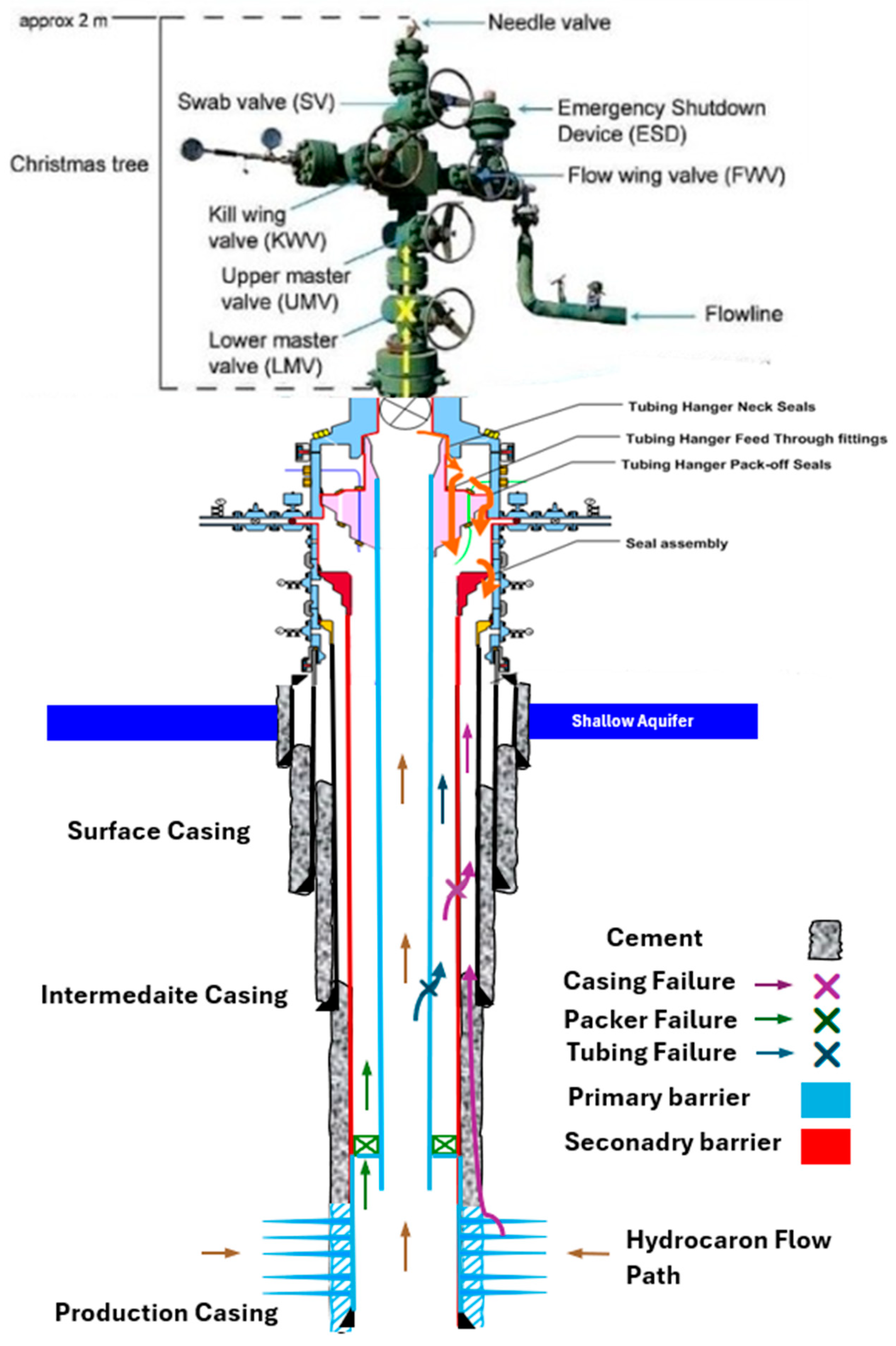
A critical aspect of the barrier philosophy is verification. Each designated WBE must be designed, installed, and tested to confirm its ability to function as intended under the anticipated operational conditions. The integrity of each barrier envelope must be demonstrable and maintained throughout the relevant well lifecycle phase. The overall technical integrity of the well is often quantitatively assessed in terms of its “tightness”, which can be related to a maximum permissible leakage rate across a specific barrier, system, or defined by other measurable parameters indicating the health of the barriers [7]. This systematic, verifiable, multi-barrier approach forms the basis for safe, well-designed, and operational across the industry. Figure 2 shows a schematic of well barrier elements and envelopes during the production phase. The primary barrier includes the tubing, packer, tubing hanger, and valves within the Christmas tree. The secondary barrier encompasses the production casing, cement, casing hanger seals, and annulus valves. This diagram also illustrates typical failure paths such as casing, tubing, and packer failures, and shows the vertical arrangement of barrier elements in relation to the shallow aquifer, ensuring zonal isolation.

4. Well Integrity Across the Lifecycle
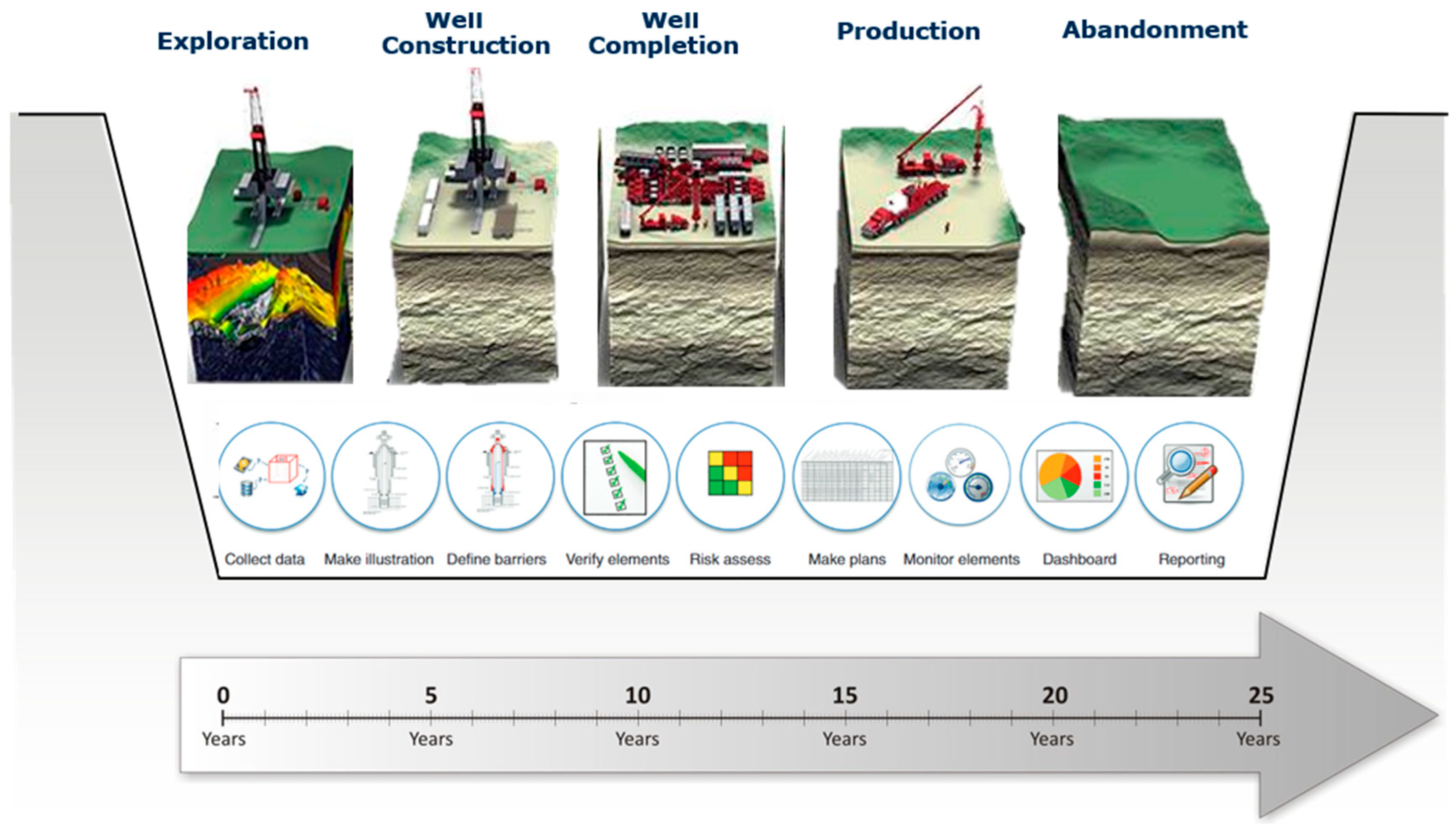
Maintaining well integrity is not a static objective but a continuous process that must adapt to the distinct challenges posed by each phase of a well’s life, from initial drilling to final abandonment. During drilling, the primary concerns involve maintaining borehole stability to prevent collapse or excessive enlargement, managing drilling fluid properties (mud weight, rheology, fluid loss) to control formation pressures, avoid excessive formation damage, and minimize mud losses into permeable zones, and navigating geological hazards like faults, unstable shales, or high-pressure zones that could compromise subsequent cementing operations or create inherent weaknesses [52,53,54]. Poor drilling practices can lead to hole instability issues that directly impact the ability to achieve effective primary cementing later. The concept of well integrity must be understood as a lifecycle responsibility, not a one-time event. Figure 3 outlines the key phases in a well’s life—exploration, construction, completion, production, and abandonment—along with the associated integrity-related tasks such as barrier verification, risk assessment, and continuous monitoring that must be tailored to each phase.
The drilling phase is arguably the most critical for establishing the well’s long-term integrity foundation. This involves running and cementing casing strings, which requires selecting appropriate casing materials and connections designed for the expected lifetime loads, ensuring adequate casing centralization for uniform cement placement, and executing the primary cementing operation meticulously to achieve complete mud removal and hydraulic isolation between zones [13,55,56]. In the completion phase, installing completion equipment (tubing, packers, safety valves) and the wellhead assembly also demands careful handling and proper installation procedures to avoid damaging components or seals [23]. Verification through pressure testing of casing, cement, and barrier components is mandatory at this stage to confirm initial integrity [16].
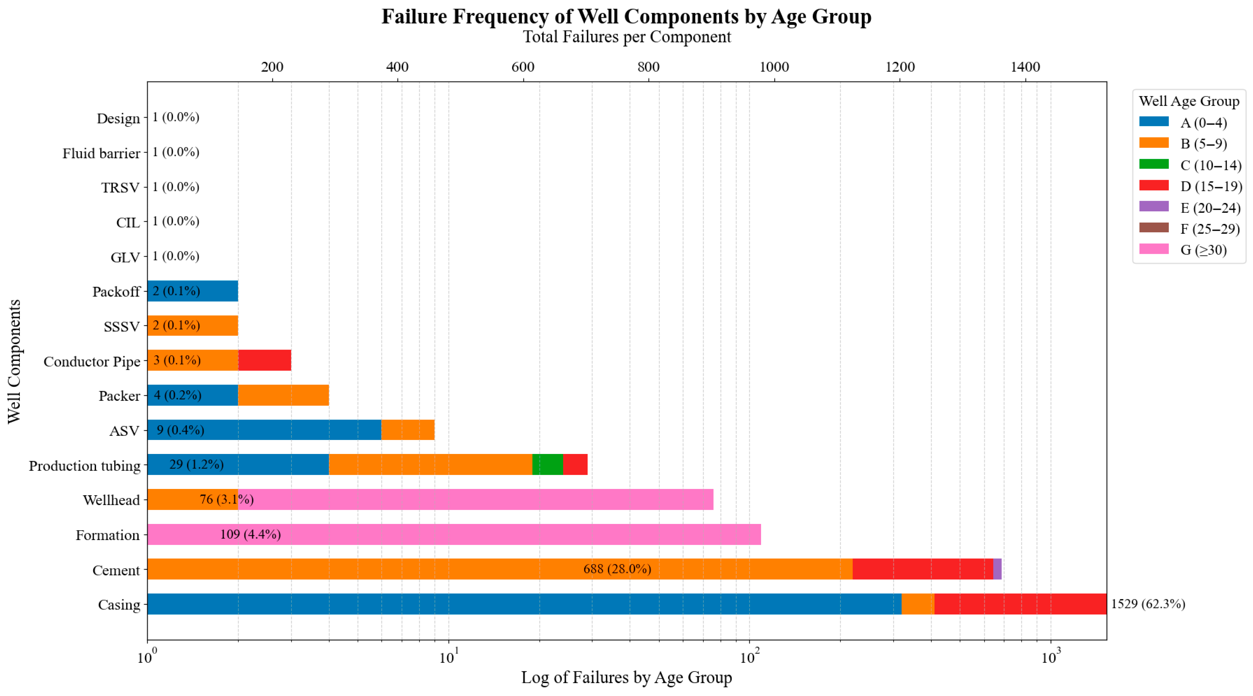
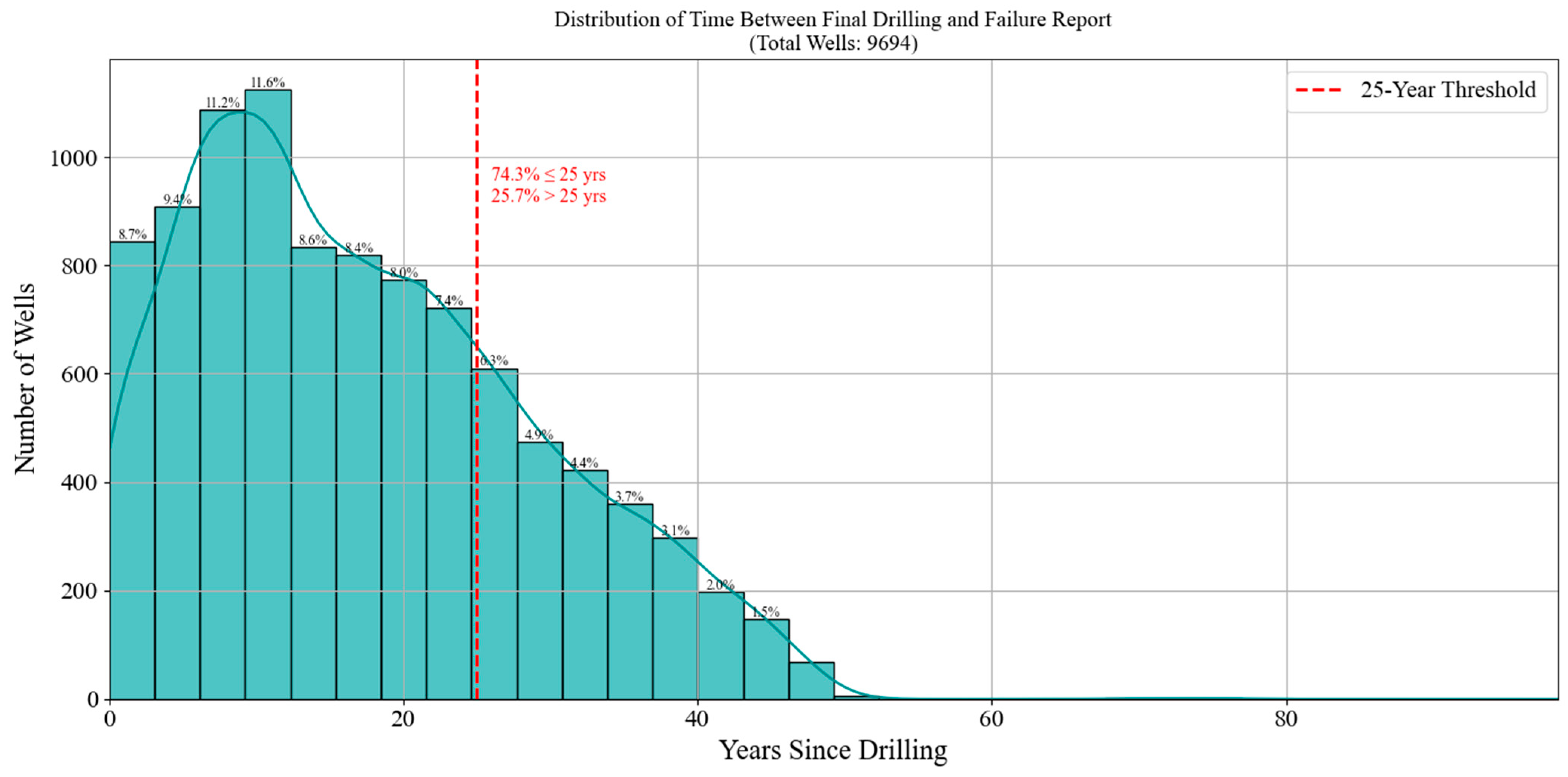
The operational phase (production or injection) subjects the well to the most prolonged and often most severe integrity challenges. Cyclic loading from pressure and temperature fluctuations during production/injection cycles, start-ups, and shut-downs can induce fatigue in casing and connections and cause debonding or cracking in cement sheaths [9,10,57]. Prolonged exposure to formation fluids or injected substances (CO2, H2S, produced water, steam, completion/stimulation fluids) can lead to progressive corrosion of metallic components and chemical degradation of cement [17,23,58]. Geomechanical changes due to reservoir depletion (compaction/subsidence) or pressurization (uplift) alter the stress state around the wellbore, potentially leading to casing deformation or shear, or compromising the sealing capacity of the caprock [59,60,61]. Intervention operations during this phase also carry inherent risks of damaging existing barriers. Understanding how component failure rates evolve over a well’s lifespan is vital for designing effective integrity management strategies. Figure 4 presents a log-scale bar chart showing failure frequencies of major well components categorized by age group. This visualization highlights the dominance of casing and cement failures and their persistence across all well ages, emphasizing the need for long-term monitoring and life-extension protocols. Statistically, casing failures represent 62.3% of all reported failures (n = 1529), followed by cement with 28.0% (n = 688), collectively accounting for over 90% of total integrity incidents. These high percentages indicate a disproportionate vulnerability in these two components, reinforcing the importance of focused design improvements and robust zonal isolation evaluations throughout the well lifespan. Analyzing the time lag between drilling and failure reporting provides insights into when integrity risks are most likely to manifest. Figure 5 shows the distribution of years between a well’s final drilling date and its first reported integrity failure across nearly 10,000 wells. The data reveal that many failures occur within the first two decades of a well’s life, highlighting the need for intensified integrity surveillance during early and mid-life stages, followed by sustained long-term monitoring. Statistical analysis shows that 74.3% of well failures occur within the first 25 years of operation, whereas 25.7% occur beyond this threshold, indicating a significant but smaller long-term failure risk that necessitates ongoing integrity assessments for aging wells.
Finally, the abandonment phase aims to permanently isolate porous formations and prevent any future leakage to the surface or between zones. This requires the placement and verification of permanent barriers, typically specialized cement plugs set across critical intervals, often supplemented by mechanical plugs [3,62]. Ensuring the long-term integrity and durability of these abandonment barriers, especially for wells used in geological storage where containment is required for centuries, or wells situated in environmentally sensitive areas, necessitates rigorous design, material selection (often using specialized plugging materials), placement techniques, and verification methods. Neglecting integrity considerations or failing to anticipate future degradation mechanisms at any stage can create latent vulnerabilities that compromise safety, environmental protection, and economic viability later in the well’s life or even long after operations cease.
Figure 5. Distribution of the number of years between final drilling and first reported failure for 9694 wells. The histogram shows a clear peak in failures within the first 10–20 years of a well’s life, after which the failure frequency gradually declines. This highlights the critical early lifecycle period for focused integrity monitoring and emphasizes the importance of long-term surveillance to capture later-onset issues [63]. Reproduced from the Alberta Energy Regulator, under the terms of the Creative Commons CC BY 4.0 license.
Energies 18 04757 g005

5. Wellhead and Surface Equipment Integrity
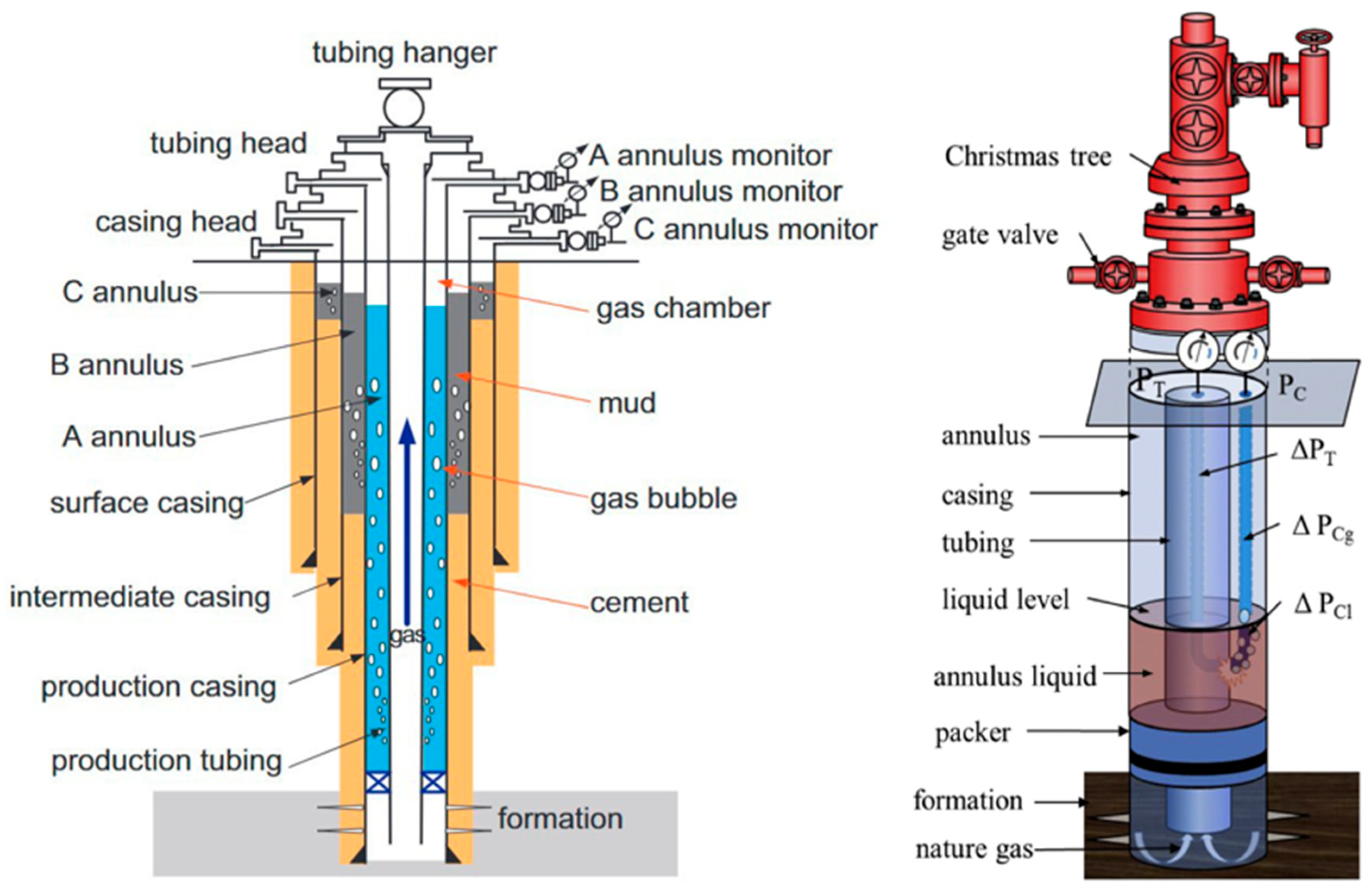
The wellhead system serves as the critical interface between the downhole environment and the surface, providing essential functions including pressure containment for all annuli and the production bore, structural support for suspended casing and tubing strings, and controlled access for monitoring and interventions [2,39]. Maintaining its integrity is paramount for surface safety, environmental protection, and operational control. Wellhead designs typically incorporate multiple sealing systems. Annulus seals (packoffs) are installed between consecutive casing hangers to isolate each annulus, while primary and secondary seals are located around the tubing hanger to contain production fluids (often relying on elastomer seals, metal-to-metal seals, or combinations thereof) [27]. Failures in these seals, often due to elastomer degradation (thermal, chemical, extrusion) or improper installation, can lead to leaks to the environment or pressure communication between different annuli, potentially contributing to SCP. A clear understanding of the wellhead system and its interaction with subsurface pressure regimes is essential for diagnosing surface casing pressure (SCP) anomalies. Figure 6 illustrates the anatomy of a typical cased wellbore system (left), including annulus pressure monitoring ports, gas migration pathways, and fluid stratification, along with a schematic of pressure distributions across casing, tubing, and annulus components (right). These visuals highlight the complexity of pressure communication mechanisms that underlie SCP phenomena.
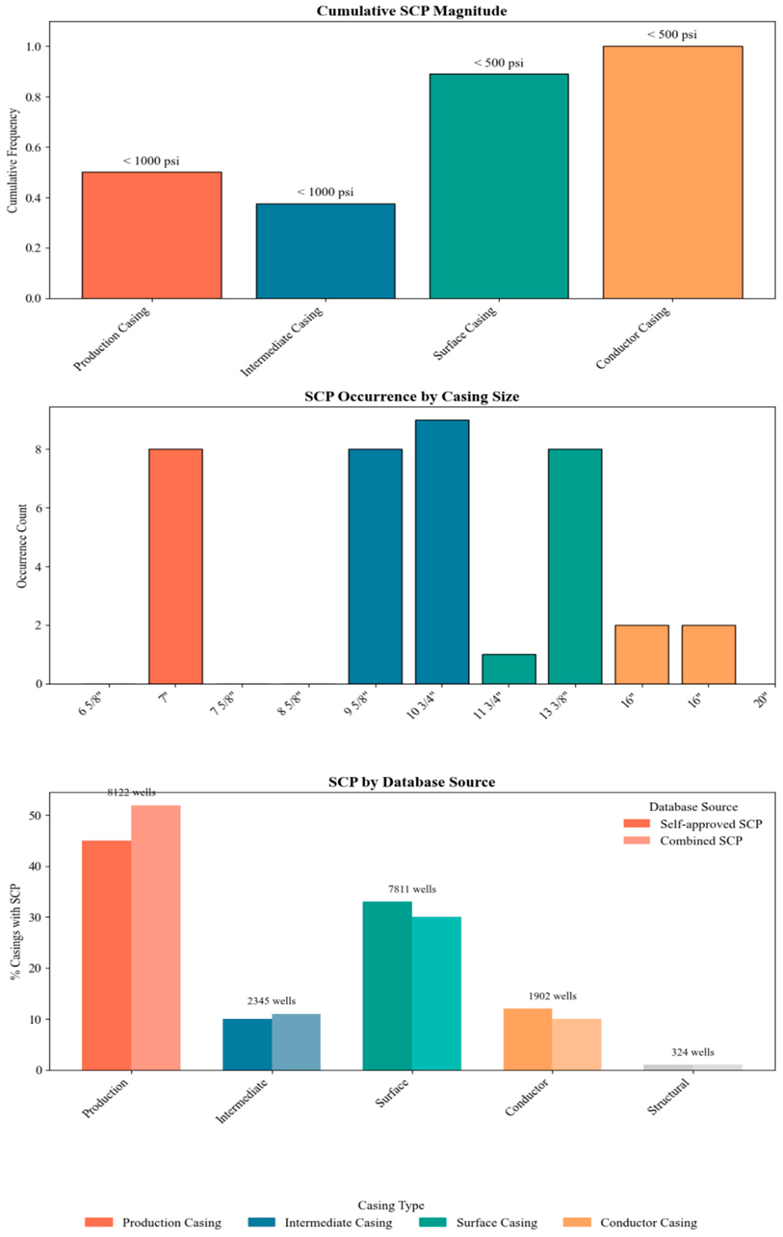
Surface casing pressure anomalies (SCP), monitored via gauges on the wellhead annulus outlets, often signal a breach in a downhole barrier (e.g., casing leak, cement failure) allowing formation pressure to reach the surface [36,64]. While the symptom is observed at the wellhead, its diagnosis and management require understanding the downhole system, guided by standards like API RP 90. To quantify the prevalence and severity of SCP, Figure 7 summarizes field data across thousands of wells. The top chart shows that the majority of sustained casing pressure (SCP) events in surface and conductor casing occur below 500 psi, whereas production and intermediate casing tend to experience SCP below 1000 psi. The middle panel indicates that SCP is most frequently reported in 9⅝”, 10¾”, and 13⅜” casing sizes, typically used in intermediate and surface intervals. The bottom panel reveals that over 50% of SCP events are associated with production casing (8122 wells), followed by surface casing (7811 wells), indicating higher SCP vulnerability in these intervals. This analysis quantitatively highlights that SCP is not only a widespread issue but also disproportionately concentrated in specific casing types and sizes. The data clearly show that production and surface casings exhibit the highest SCP frequencies, underscoring the need for rigorous wellhead pressure monitoring and annular barrier integrity throughout the well lifecycle.
Figure 6. Combined schematic showing the structure and pressure dynamics in a typical oil or gas well. (Left): Vertical cross-section of a well with multiple concentric casing strings and annuli (A, B, C), showing annulus monitors, potential gas migration, and fluid interfaces [65]. Reproduced with permission from [65]. (Right): Pressure distribution along the wellbore, with annotations for differential pressures across tubing (ΔP_T), casing (ΔP_Cg), and annulus liquid column (ΔP_Cl), as well as the roles of packers, formation gas, and wellhead components such as the Christmas tree and gate valves. These visual highlights critical zones for pressure monitoring and fluid communication, relevant to sustained casing pressure (SCP) interpretation [66]. Reproduced with permission from [66].
Energies 18 04757 g006
Figure 7. Summary of sustained casing pressure (SCP) metrics: (top) cumulative SCP magnitude categorized by casing type; (middle) SCP occurrence count by casing size; (bottom) percentage of casings with SCP in both self-approved and combined datasets, including total number of wells analyzed per casing type. Data adapted from [67,68,69]. Reproduced with permission from [67].
Energies 18 04757 g007
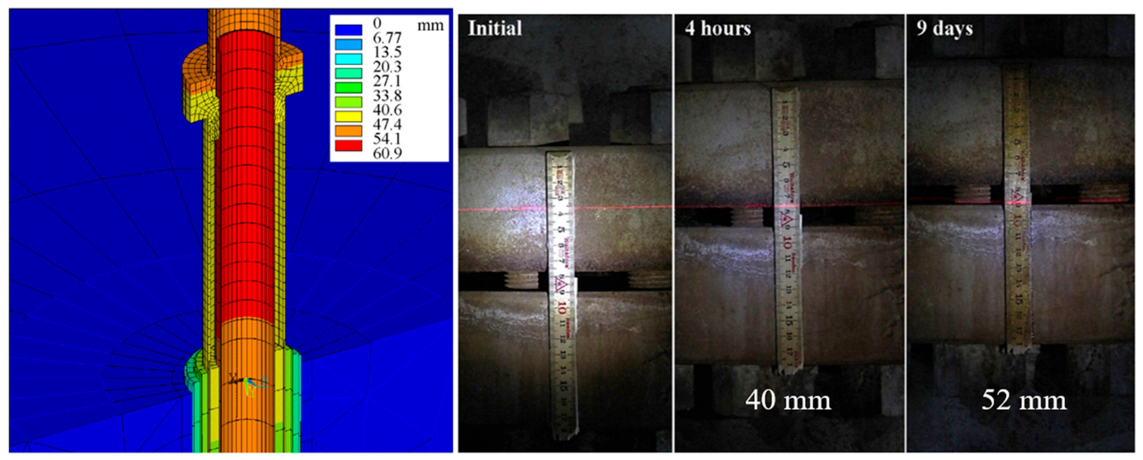
Wellhead components themselves are subjected to significant mechanical and thermal stresses that can challenge their integrity over time. Thermal expansion and contraction of the long casing and tubing strings during production and injection cycles impose substantial axial loads (tension and compression) and potential bending moments on the wellhead assembly, potentially leading to fatigue, yielding, or connection failures, particularly in high-temperature applications like thermal EOR or deep geothermal wells [9]. Figure 8 demonstrates this effect with an uplift of 52 mm observed on the HE-46 well during extended flow testing [70]. Such thermal movement must be accounted for in wellhead and spool design, as it can impact sealing integrity, stress distribution across flanges and bolts, and overall structural stability. Mechanical loads, such as those transferred from riser systems due to vessel motion and environmental forces (waves, currents) in offshore installations, or those arising from ground subsidence around onshore well pads, can also induce significant stress, deformation, and fatigue in the wellhead structure and its connections [24]. Reference [71] utilized coupled finite element modeling to demonstrate how these dynamic offshore loads can severely impact wellhead integrity, potentially causing failure under extreme sea states and underscoring the critical importance of fatigue analysis in design.
Connection integrity within the wellhead assembly itself—including flanged connections, studded connections, valve bodies, and valve stem packings—is vital. Leaks can occur due to improper bolt tensioning, gasket damage or degradation, corrosion of sealing surfaces, or failure of valve stem packings [72]. Ensuring the correct selection, installation, and maintenance of these static and dynamic seals is crucial.
Monitoring strategies for wellhead integrity typically involve regular visual inspections for leaks or damage, periodic pressure testing of annulus seals and valves according to regulatory or company standards, non-destructive testing (e.g., ultrasonic, magnetic particle, radiographic) of critical components, and continuous monitoring of annulus pressures [1]. Modern approaches are exploring the use of sensor-integrated wellheads incorporating permanently installed sensors for real-time monitoring of pressure, temperature, strain, or vibration, potentially feeding data into digital twin systems for enhanced surveillance and diagnostics [73,74]. Mitigation strategies rely on robust design accounting for all anticipated thermal, pressure, and external loads (including fatigue analysis where relevant), careful material selection appropriate for the service environment (considering temperature, pressure, corrosion, and H2S resistance), adherence to strict installation and maintenance procedures (including correct torque and test), and proactive management of any observed annular pressure.
Figure 8. Modeled wellhead displacement 9 days after discharge of well HE-46 (180° symmetry expansion) (Left). Photographic series of the wellhead displacement of well HE-46 during discharge, showing an upward movement of approximately 52 mm in the master valve spool due to thermal loading (Right) [75]. Both figures reproduced from [75].
Energies 18 04757 g008

6. Failure Mechanisms in Well Integrity

Understanding the diverse mechanisms that can compromise well integrity is fundamental to effective prevention and mitigation. These failures originate from the complex interplay of mechanical loads, geochemical interactions, operational conditions, and material degradation over time. They can be broadly categorized based on their primary drivers.

6.1. Mechanical Failures

These involve the physical breakdown, deformation, or loss of sealing function of wellbore components under applied or induced stresses [10].

6.1.1. Casing Collapse

Collapse occurs when external radial pressure exceeds the casing’s ability to withstand compressive loads, which can be exacerbated by factors such as poor cement bonding, formation compaction, or cement voids. As early as 1972, Evans and Harriman [76] conducted hydraulic collapse and mechanical load tests to investigate the role of cement sheaths with various strengths and configurations on casing collapse resistance. They found that full cement sheaths could improve collapse strength by up to 23%, while cement sheaths containing voids above a certain size provided very limited protection. Reference [77] reported that casing failure modes are interrelated, with collapse or burst primarily due to radial stress. Tensile failure can also occur due to axial tension, and connection jump-out may result from compression or tension. Interestingly, one failure mode may reduce the likelihood of one failure mode but promote another. Based on the mathematical theory of elasticity [78] applied Lame’s solutions to the stress distribution of cemented concentric casings under nonuniform loading. They showed that collapse resistance could decrease by as much as 70–85% when loading varies from uniform to nonuniform. Reference [79] used finite element analysis to simulate the stress distribution of casing-cement sheath-formation systems under various collapse loading conditions. They found that the API Bulletin 5C3 equations were too conservative and failed to account for the cement sheath’s effect on collapse resistance, showing that collapse resistance could increase by up to 62% depending on the cement’s mechanical properties. Reference [80] proposed that more ductile cement might absorb more internal stress and reduce collapse loading on the casing, although such cement properties are difficult to achieve, even with recent advances in cement additives [81,82]. Reference [83] studied the effects of cement voids and channels on nonuniform loading and found that collapse resistance could drop by up to 60% in the presence of voids, with the degree of the effect depending on horizontal stress and pore pressure. Reference [84] identified four mechanisms of casing collapse resulting from reservoir compaction: buckling, bending, traction, and shear. These mechanisms are particularly problematic in salt layers with significant uplift potential. Reference [85] conducted sensitivity analyses and proposed that void location, Poisson’s ratio, and Young’s modulus of cement significantly impact casing collapse resistance, while eccentricity and void shape have minimal effects. Reference [10] demonstrated that voids and micro-annuli at the casing-cement interface could reduce collapse resistance by up to 60%, with voids and cement channels proving far more detrimental than eccentricity, which still impacts casing integrity. Reference [86] emphasized that collapse failure results from mechanical loading caused by the casing, cement, and surrounding sand. Furthermore, during production, stress variations resulting from fluctuating flow rates and dynamic loading also contribute to casing collapse. This phenomenon primarily occurs when unequal external loads exceed the casing’s yield strength, leading to deformation from a circular to an oval shape [87]. Collapse failures are categorized into yield, transitional, elastic, and plastic types, and the industry standard for these classifications uses the slenderness ratio (diameter-to-thickness ratio). However, reference [88] suggested that casing collapse could be seen as abnormal displacements of rock formations, causing the casing to fail. Reference [89] noted that length-to-diameter ratios greater than 10 had minimal effects on collapse resistance, but initial ovality significantly decreased collapse resistance. Reference [90] argued that cement eccentricity had negligible effects on casing collapse strength when the cement’s elasticity modulus is similar to that of the formation, suggesting that the casing could be considered concentric. To ensure well integrity, thorough geologic surveys and appropriate cementing programs are essential before drilling. Laboratory tests of cemented pipes further emphasize the importance of proper cementing in improving casing collapse resistance, highlighting the critical role of casing and cementing design in preventing collapse.

6.1.2. Casing Burst

Burst failure of the casing occurs when internal pressure exceeds the casing material’s yield strength, with the magnitude of this risk depending heavily on external loads resisting the internal pressure. Reference [91] developed a model for predicting the burst capacity of degraded casings that have undergone crescent wear. Their model calculates the varying hoop strength of the casing based on wall thickness and shows that the crescent shape model offers a more realistic estimation of casing burst resistance compared to the API and Nadal models. Reference [92] further examined the impact of residual stress on C110 casing grades using numerical simulations and concluded that cracks play a significant role in burst or collapse failures, especially in deep-water well applications. Reference [9] conducted studies using finite element analysis (FEA) on burst-induced stress in cemented wellbores, revealing that cemented casings experience lower stress concentrations, thereby reducing the burst risk compared to uncemented systems. Specifically, they found that casing confined within a cemented wellbore showed a 58.4% reduction in von Mises stress, thereby permitting the use of lower-yield pipe grades, such as K55, which reduces material costs without compromising integrity. In contrast, uncemented casings required higher-grade materials, like N80, to withstand similar conditions. This emphasizes that burst failure is more likely in uncemented casings, particularly in open-hole completions. Furthermore, Reference [93] criticized the API design equation for burst and collapse, noting that it does not address the body’s response when axial stress exceeds the material yield strength. In thermal recovery methods, like SAGD and CSS, where operating temperatures exceed 390 °F (199 °C), casing yielding is common, exacerbating strain from axial loading and internal/external pressure differentials [94] also investigated the burst stress in cemented casings with particulate annuli and found that bonded annulus fill materials provided more than a 5% increase in the casing’s nominal burst rating. Recent studies have expanded burst strength models by incorporating wear and corrosion effects, with [95] proposing models that consider mechanical-electrochemical interactions in the burst failure mechanism of worn casings. These models have shown that coupling wear with corrosion accelerates degradation and stress concentration, which significantly impacts burst strength predictions, especially in ultra-deep wells. These developments highlight the need for comprehensive models that account for wear, corrosion, and their combined effects on casing integrity in real-world conditions.

6.1.3. Casing Buckling

Buckling failure, including sinusoidal and helical modes, is a critical failure mechanism in deviated and horizontal wells, often resulting from axial compression. Reference [96] initially proposed the concept of casing string bending instability, which laid the foundation for subsequent research in casing deformation under axial loads. Scholars such as [97] expanded on this theory, detailing how axial stress and casing stiffness contribute to the onset of buckling and the transition between sinusoidal and helical buckling modes. These studies demonstrated that when axial compression increases, sinusoidal buckling may evolve into helical buckling, especially in long horizontal and deviated wells. The casing string can reach several distinct states, each with specific buckling configurations. These include the linear stable poised state, sinusoidal buckling state, helical buckling state, and self-locking state. Transitions between these states occur at three critical points determined by axial load, casing stiffness, and hole geometry. As the axial load increases, buckling configurations evolve, and the casing may shift from linear stability to sinusoidal buckling, followed by helical buckling and, in some cases, self-locking.
Flutter instability, a phenomenon described by [98], adds another dynamic risk to casing integrity. Flutter occurs when small oscillations within a structure are amplified due to interaction with external forces, causing large and uncontrollable deformations. This form of instability is particularly concerning in horizontal wells, where casing is subjected to complex stress states and dynamic loading during operations such as hydraulic fracturing. Cyclic thermal loading also plays a significant role in casing buckling. Reference [99] noted that thermal cyclic loads could induce casing buckling in combination with formation shear movements, leading to permanent deformation or failure. These thermal and mechanical loads can further complicate casing stability, especially when combined with high axial forces and complex wellbore geometries, as seen in unconventional reservoir wells.
Buckling behavior is also influenced by the wellbore geometry and the interactions between the casing and the surrounding formation. As casing is subjected to different mechanical forces, such as axial tension and compressive forces, as well as changes in pressure and temperature, the casing may experience varying degrees of deformation. The phenomenon of casing buckling is often exacerbated in wells with poor cementing, as casing deformation can lead to debonding and cement failure, further compromising well integrity. Several models have been developed to predict casing buckling under various conditions. References [100,101] applied finite element analysis (FEA) to simulate casing buckling in horizontal and extended-reach wells, factoring in wellbore tortuosity and other imperfections. These models are particularly useful in unconventional reservoirs, where high lateral forces, friction, and non-uniform wellbore geometries are common. In recent years, studies have also focused on the influence of formation characteristics, including lithology and pressure differentials, on casing stability. References [102,103] examined how formation shear and heterogeneity affect casing buckling, particularly in shale gas and tight oil wells. Their research found that formation movements and the interaction between the casing and formation can significantly increase the likelihood of buckling, especially when combined with high-pressure conditions.
Further research by [104,105] emphasized the importance of wellbore conditions, such as tortuosity and cement integrity, in predicting and mitigating casing deformation. They proposed using advanced numerical simulations to optimize casing design, particularly in wells with complex geometries, to prevent buckling and ensure long-term well integrity.

6.1.4. Casing Fatigue

Casing fatigue failure is a serious and increasingly common issue in oil, gas, and geothermal wells, particularly those exposed to cyclic thermal or pressure loads. This failure mode is caused by the progressive initiation and growth of microcracks due to repeated loading and unloading beyond the material’s endurance limit. Operations such as steam-assisted gravity drainage (SAGD), cyclic steam stimulation (CSS), geothermal energy production, and multistage hydraulic fracturing are especially prone to such failures. During cyclic operations, such as steam injection, the casing undergoes significant thermal expansion, inducing axial compressive stress. This is followed by tensile stress during cooling phases, such as soaking or production. The alternating stress environment promotes fatigue crack initiation and propagation, especially at casing connections, welds, or areas with material defects [57,106]. These localized zones often act as stress concentrators, making them prime sites for fatigue failure. Offshore wells also face added fatigue risks due to dynamic environmental loads transferred from riser and wave motion to the wellhead and casing system [107].
Field investigations have documented numerous cases where casing fatigue led to failure at or near the surface casing shoe, above the top of cement, or around perforation intervals. For example, Reference [108] reported fatigue cracks in API 8-Round casing connections, often at the last engaged thread, due to drillstring-induced vibration, inadequate make-up, and poor landing tension. These failures occurred predominantly in vertical wells where buckling and insufficient cement bonding allowed dynamic movement and cyclic stresses to accumulate.
Recent advancements in modeling and diagnostics have enabled more accurate fatigue life prediction. Reference [109] emphasized that cyclic operations, particularly in multistage hydraulic fracturing, cause temperature and pressure variations that cyclically load the casing. Their integrated approach combines thermal-flow simulation with multistring stress analysis to assess fatigue life at critical locations such as casing joints and couplings. These models often use strain-based approaches like the Manson–Coffin method and energy-based techniques such as the Smith–Watson–Topper (SWT) model, which account for plastic deformation under low-cycle fatigue [57,110].
Experimental and numerical evidence support that fatigue resistance is heavily influenced by thread geometry, make-up position, material selection, and cement integrity. Stress concentrations at the root of the last engaged thread remain a key factor in connection failures [111]. The use of premium connections and increased wall thickness around threads can mitigate such effects.
Casing failure preventive strategies include the following:
Selecting high-strength, fatigue-resistant alloys such as Q125 or L80 with good ductility.
  • Optimizing casing design to minimize stress concentrations.
  • Improving cement placement and bonding to constrain casing movement.
  • Ensuring proper landing tension and make-up torque.
  • Using advanced fatigue models to evaluate life cycles.
  • Deploying real-time monitoring systems to detect early signs of fatigue degradation.
In summary, fatigue failure of casing is a multifactorial challenge that arises from repeated mechanical and thermal stresses during well operations. Casing failure prevention requires an integrated strategy involving materials science, geomechanics, engineering design, and continuous operational oversight. Addressing this issue is vital to ensuring long-term well integrity, environmental protection, and operational safety.

6.1.5. Casing Erosion and Wear

Casing erosion and wear represent critical threats to the long-term structural integrity of oil and gas wells. Erosion refers to the removal of material from the casing inner wall due to the high-speed impingement of abrasive particles, such as sand or proppants, transported by fracturing or production fluids. Wear, on the other hand, is typically caused by mechanical interaction—such as frictional contact between the casing and rotating or reciprocating components like drill strings, tool joints, or coiled tubing. Both mechanisms can significantly reduce casing wall thickness, leading to strength degradation, pressure containment loss, and potential well integrity failure.
Erosive wear is particularly aggressive in environments involving high fluid velocities, cyclic production, and directional or horizontal drilling. Reference [112] demonstrated through gas-solid two-phase flow simulations that factors such as dog-leg severity, flow rate, particle size, and temperature play a dominant role in accelerating casing erosion in gas storage wells. Increased temperature weakens the material’s modulus of elasticity, making casings like N80 more susceptible to erosion compared to higher-grade materials such as P110.
In the context of hydraulic fracturing, casing perforations face a unique erosion risk. Experimentally observed that high sand concentrations and flow velocities result in non-uniform perforation expansion, particularly at the inlet side of the perforation. SEM imaging revealed erosion mechanisms including ploughing, cutting, and brittle cracking, which intensify under increased flow and particle loads. Similarly, [113] showed that casing materials such as Q125HC experienced peak erosion at impact angles of around 45°, where the combined horizontal (cutting) and vertical (impact) forces are maximized.
CFD and FEM studies further support that erosion is concentrated in geometric transitions, such as elbows and perforation edges, due to particle trajectory deflection and local turbulence [114,115]. The erosion rate increases non-linearly with flow velocity and sand content, indicating that even moderate increases in these parameters can lead to accelerated casing degradation. The selection of casing grade significantly influences susceptibility to various failure mechanisms, including erosion, wear, and fatigue. Figure 9 presents two key trends: (A) the usage distribution of different casing grades across application types such as injection, HPHT, shale gas, and deepwater operations, and (B) the corresponding failure modes associated with each grade. The figure shows that while high-strength grades like P110 and Q125 are preferred in demanding environments, they also exhibit diverse failure patterns—including wear, buckling, and fatigue—underscoring the importance of grade-specific design and monitoring strategies.
Wear, meanwhile, is often driven by contact stresses during operations like backreaming, sliding, or rotating off-bottom. The conventional wear modeling approach widely adopted in the industry considers wear as a function of frictional work from rotating tool joints. Recent improvements using the stiff-string model provide better predictions by accounting for bending stiffness and varying contact positions along the casing wall. This modeling enables the identification of multiple groove wear zones per cross-section, better matching field data from ultrasonic and caliper logs.
Adhesive and abrasive wear types are commonly observed in directional wells. Refs. [116,117] described that wear evolves from surface grooving to structural weakening, with wear rates heavily influenced by tool joint contact angle, pipe-body hardness, and drilling mud composition. Combined erosion-wear-corrosion mechanisms become especially destructive when Cl ions are present, impairing protective surface films on casing steel and promoting localized damage.
Figure 9. Casing grade utilization and associated failure trends [118]. (A) Stacked bar chart showing the frequency of casing grade use across different applications such as injection, HPHT/geothermal, shale gas, deepwater, and others. The dashed black line represents the cumulative number of wells using each grade. Grades like P110 and N-80 are widely applied across demanding environments. (B) Line plot illustrating the distribution of casing failure mechanisms (e.g., fatigue, buckling, wear, collapse) by grade. Notably, high-strength grades such as P110 exhibit a broader range of failure modes, highlighting the need for tailored design practices and robust connection selection. Reproduced with permission from [118].
Energies 18 04757 g009
Material selection plays a pivotal role in mitigating erosion and wear. High-strength grades like P110 and Q125HC exhibit improved resistance compared to N80, but even these can degrade under extreme flow and thermal cycles. Optimization efforts also include applying erosion-resistant coatings, using sand screens, reducing toolpath contact, and controlling pump rates and sand loadings.
In summary, casing erosion and wear are complex, intertwined failure modes influenced by hydraulic conditions, mechanical contact, and material performance. Modern predictive models, validated by experimental and field data, are essential for anticipating wear patterns and implementing effective mitigation strategies. A robust casing integrity plan should integrate advanced simulation tools, continuous monitoring (e.g., caliper logs, ultrasonic imaging), and proactive design choices tailored to site-specific challenges.

6.1.6. Connection Failure

Casing connection failure is a major concern in the oil and gas industry, often compromising well integrity and operational safety. These failures occur at the threaded joints that link individual casing pipes into a continuous string within the wellbore. These joints, typically involving a pin and box thread system secured with couplings, must maintain structural and sealing integrity throughout the life of the well. When these connections fail, they can lead to leaks, blowouts, and full separation of casing segments, especially under high thermal loads, hydraulic fracturing, or deep offshore pressures [119]. Finite element analyses have shown that API Short Round and API Buttress connections often suffer from high stress concentrations at the last engaged thread due to their geometric profiles and the stiffness disparity between the pin and box, contributing to fatigue initiation [120]. Grooving at the first and last engaged threads has been proposed as a solution to improve stress distribution and delay fatigue onset [120].
The causes of casing connection failure are multifaceted. Improper installation is a primary contributor; incorrect torque application or misalignment can lead to loose or damaged threads. Operator error during handling or makeup—such as dropping or dragging the pipe—can weaken joints before they are run into the well [121]. Corrosion is another critical factor, particularly in wells exposed to hydrogen sulfide, seawater, or acidic fluids. Galvanic corrosion may occur when incompatible metals are used, accelerating degradation. Reference [119] emphasized corrosion’s role, especially in aging fields with prolonged chemical exposure. Mechanical stress from pressure and temperature cycling imposes thermal expansion and contraction, which can fatigue the connection over time. Stress simulations in gas storage wells under alternating loads indicate that von Mises stress accumulates near the first engaged thread, underscoring the need for improved designs in cyclic environments. Eccentric loading due to formation irregularities or casing misalignment further exacerbates localized stress. Field data underscores the prevalence of connection failures. In certain shale plays in the United States, it has been reported that 20% to 30% of horizontal wells experience casing failures, with a significant portion attributed to the connections [122]. Investigations by Ref. [123] show that over 50% of casing failures in their case files involved connections. In thermal recovery applications, high temperature cycling has led to failure rates significant enough to necessitate premium thread designs. Studies indicate that most failures are not due to inherent design flaws but to off-design loading or inconsistent makeup procedures. Reference [119] observed that actual operating loads often exceed those anticipated during design, revealing a performance gap. In geothermal wells, thermal cycling exceeding 290 °C has shown that standard connections are inadequate, whereas properly evaluated premium connections demonstrated superior structural and sealing performance under ISO/PAS 12835 protocols [124,125].
The consequences of casing connection failure are substantial. Loss of well integrity can lead to uncontrolled hydrocarbon release, environmental contamination, and safety hazards for personnel. Failures may trigger regulatory penalties, environmental remediation, and financial loss [121]. Operationally, such events require workovers, sidetracks, or recompletions, causing significant downtime, especially in high-production or offshore wells. Research into multi-axial loading in horizontal wells has confirmed that fatigue and plastic deformation typically originate near the thread roots and propagate under alternating loads, often exacerbated by thread eccentricities and stress risers [126].
Field operators have adopted training, procedural controls, and advanced engineering techniques to reduce the likelihood of connection failure. Correct torque application, ensured through automated power tongs, reduces human error and improves installation consistency [126]. Advanced inspection tools like ultrasonic and electromagnetic logs help detect early damage. Leak detection systems offer proactive fault identification. Material and thread selection should match specific well conditions. Premium connections with improved sealing and load-bearing capabilities are essential in high-stress wells. API Specification 5CT (2018) sets minimum thresholds, but bespoke designs and finite element evaluations offer more accurate assessments of connection performance [120]. For geothermal and high-pressure wells, studies recommend full-scale testing combined with analytical models to more accurately predict sealing behavior and fatigue life [124].
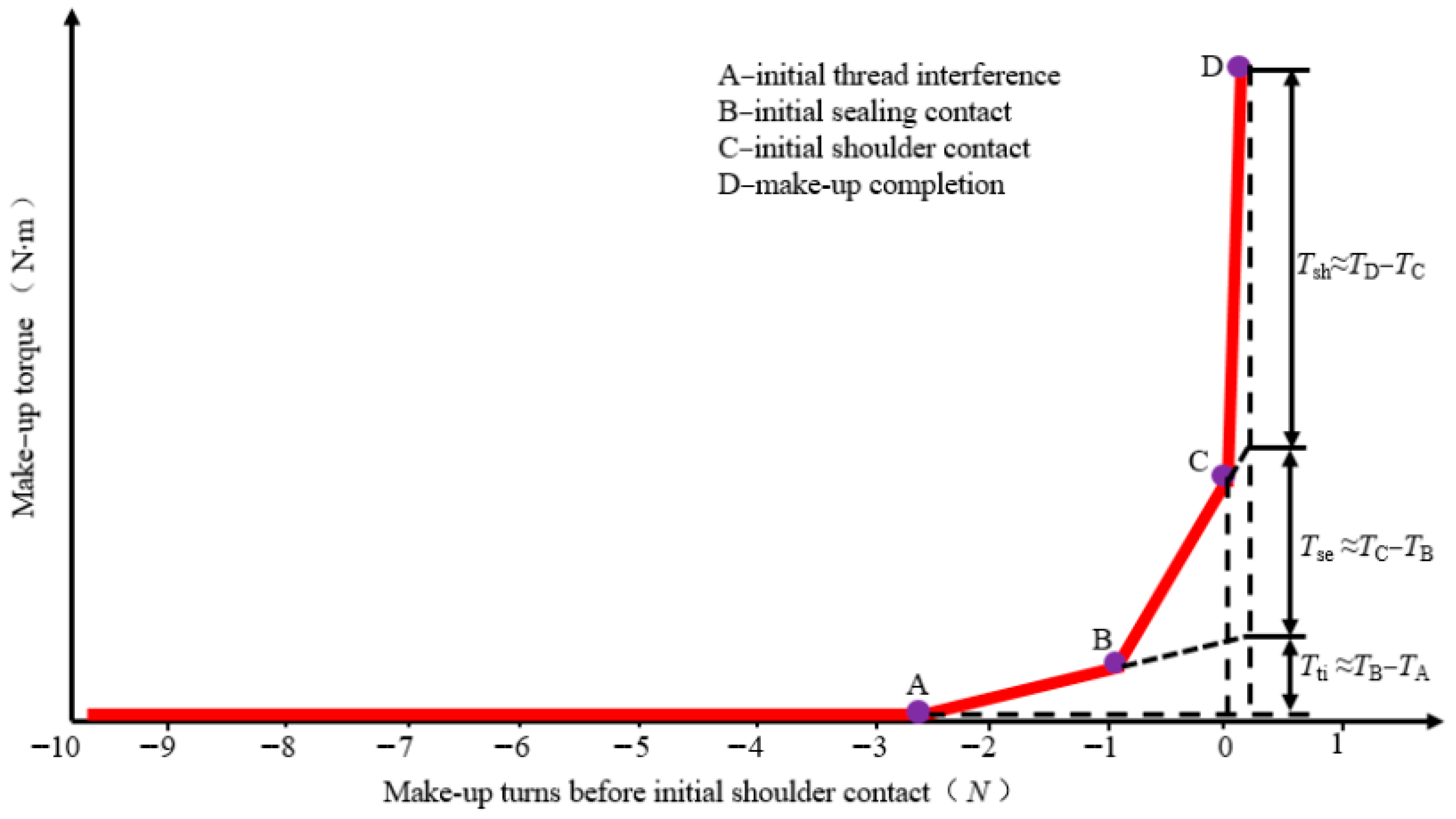
As wells become deeper and more complex, maintaining casing connection integrity becomes increasingly difficult. While advancements in thread design and automated installation have reduced some risks, challenges remain in cyclic loading, corrosion, and operational variability. Future efforts should focus on improving fatigue resistance, real-time monitoring, and predictive analytics powered by AI. By understanding the full range of operational conditions and incorporating this into design and execution, the industry can significantly reduce casing connection failures and support more sustainable, safe oil and gas production. Understanding the torque-turn relationship during connection makeup is fundamental for ensuring both mechanical strength and sealing integrity. Figure 10 presents a typical torque versus makeup turn curve, identifying four key engagement stages: (A) thread interference, (B) sealing contact, (C) shoulder contact, and (D) makeup completion.

6.1.7. Installation Damage

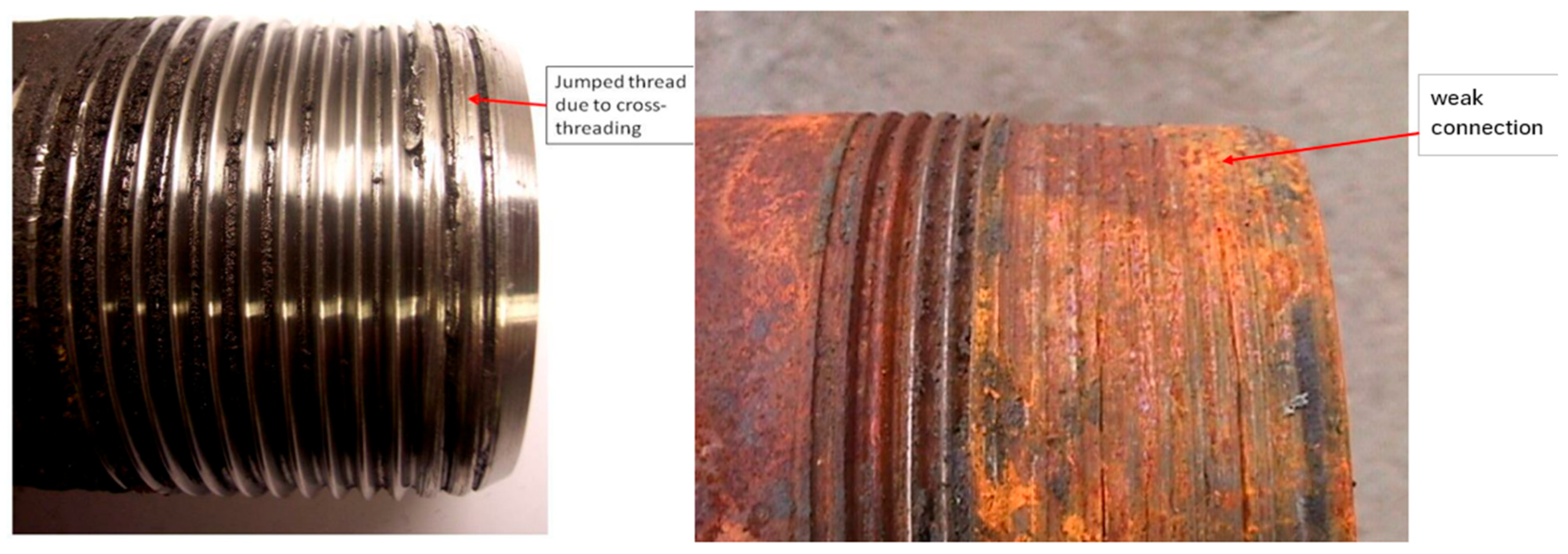
Installation-induced damage is often overlooked but can initiate casing stress concentrations from the start of well construction. During installation, bending and torsional loads may arise from forced passage through doglegs or curved sections. Reference [128] recommended tension safety factors to prevent failures during running-in-hole, though excessive conservatism may unnecessarily increase cost. Reference [129] warned that failure to model localized loads can lead to elongation or collapse during installation. An emerging trend, Drilling with Casing (DwC), is used to reduce time and cost in shale plays. However, as noted by Ref. [130], casing systems are not traditionally designed for the mechanical abuse sustained during drilling operations, which can compromise their post-installation sealing and load-bearing capabilities. Visual evidence of thread damage during installation highlights the mechanical vulnerabilities that can compromise connection performance. Figure 11 shows two common types of connection damage: the left image displays a “jumped thread” caused by cross-threading during improper makeup, while the right image illustrates a severely corroded and weakened connection due to prolonged environmental exposure. Both examples demonstrate how poor handling, improper installation, or insufficient corrosion protection can result in sealing failure and reduced load capacity.
To address these numerous and interconnected failure modes, modern operators must implement a holistic casing design and monitoring strategy. This includes selecting appropriate casing materials (e.g., corrosion- and wear-resistant alloys), improving connection technologies using AI-assisted systems, and deploying real-time monitoring tools such as fiber-optic sensors and acoustic imaging. Numerical simulations, such as finite element analysis (FEA) and computational fluid dynamics (CFD), are increasingly used to model complex casing behavior under realistic stress conditions. Industry standards like API RP 5C5 [131] and ISO 13679 [132] are under revision to accommodate the evolving demands of HPHT and unconventional wells. Ultimately, maintaining casing integrity requires a deep understanding of all potential failure mechanisms, early detection strategies, and proactive intervention technologies to ensure safe, long-term hydrocarbon production.

6.2. Geochemical Failures

These failures stem from adverse chemical reactions between wellbore construction materials and the surrounding downhole environment, including formation fluids and injected substances [10,51].

6.2.1. Cement Chemical Degradation

In addition to mechanical stresses, the cement sheath can be chemically attacked and degraded by certain components of formation fluids if it comes into contact with, particularly if zonal isolation is breached (e.g., via micro-annuli, cracks, or channels) or if corrosive fluids permeate through the cement matrix itself over long periods. Chemical degradation is a time-dependent process, with the extent of damage accumulating over decades of exposure.
  • Carbonation (CO2 Attack): Dissolved CO2 in formation water, injected CO2, or produced fluids containing CO2 can react with the alkaline hydration products of Portland cement, primarily calcium hydroxide (CH) and calcium silicate hydrates (C-S-H) gel [133,134,135].
    Mechanism: CO2 reacts with CH to form calcium carbonate (CaCO3). This reaction initially reduces permeability in the carbonated zone but also consumes CH, lowering the pH. At lower pH, the primary strength-giving C-S-H gel becomes unstable and decalcifies (calcium is leached out), losing its binding capacity and converting to silica gel. The overall result is a significant loss of strength, increased porosity, and increased permeability in the degraded zone over time.
    Occurrence: A major concern for long-term integrity in CO2-rich reservoirs (sour/sweet gas), gas storage wells (especially when cushion gas mixes with formation water), and particularly CCS wells where the cement is exposed to high concentrations of wet CO2 for extended periods. The rate of degradation is influenced by CO2 partial pressure, temperature, pressure, water saturation, and flow rate [136,137,138].
  • Sulfate Attack: Sulfates (SO42−) present in formation water or injection water can react with the calcium aluminate hydrate phases (formed from C3A hydration) and calcium hydroxide in Portland cement [139].
    Mechanism: Reactions form expansive minerals like ettringite and gypsum. These expansive minerals generate internal stresses within the cement matrix, leading to expansion, cracking, softening, loss of strength, and loss of bonding [140].
    Occurrence: Can be an issue in formations with high sulfate concentrations or when using high-sulfate injection water. Using sulfate-resistant Portland cements (API Type II or V, with low C3A content) or non-Portland-based cements designed for sulfate resistance can mitigate this risk.
  • Acid Attack (H2S, Organic Acids): Acidic fluids (low pH) can directly dissolve the alkaline hydration products (CH and C-S-H) of Portland cement, leading to increased porosity, permeability, and loss of structural integrity [141]. H2S dissolved in water forms a weak acid, and its presence can accelerate cement degradation. Organic acids present in some reservoir fluids can also be aggressive, particularly at high temperatures.
  • Leaching: Flowing formation water (even seemingly non-aggressive water) can slowly dissolve and carry away soluble components of the cement matrix, particularly calcium hydroxide (CH), over very long periods. This process increases porosity and permeability, potentially creating or enlarging leak paths, especially in fractured or already damaged cement. This is a long-term process that can be accelerated by high flow rates or low pH fluids [142].
  • Magnesium Attack: Brines rich in magnesium chloride or sulfate can also degrade cement through complex reactions that replace calcium phases with weaker magnesium phases like brucite (Mg(OH)2) and magnesium silicate hydrates, leading to strength loss and increased permeability [143].

6.2.2. Casing Corrosion

Electrochemical degradation of steel casing is a pervasive issue [17,22].
  • CO2 Corrosion (Sweet): Carbon dioxide (CO2) dissolves in water to form carbonic acid (H2CO3), a weak acid that is highly corrosive to carbon steel [144].
    Mechanism: Carbonic acid dissociates in water, providing hydrogen ions (H+) for the cathodic reaction. The anodic reaction is the dissolution of iron (Fe). Protective iron carbonate (FeCO3) scales can form on the steel surface, which can significantly reduce corrosion rates if they are dense, adherent, and continuous. However, their stability depends heavily on temperature, pH, CO2 partial pressure, and flow conditions. If the scale is porous, non-adherent, removed by high flow rates or pigging, or disrupted by pitting, rapid localized corrosion (often severe pitting) can occur beneath the scale.
    Factors: Corrosion rates increase significantly with CO2 partial pressure (higher partial pressure means more dissolved CO2 and lower pH), temperature (up to a certain point, then potentially decreasing at very high temperatures if stable, protective scales form), and flow velocity (inhibiting scale formation or causing erosion of existing scale) [145]. The presence of a free water phase wetting the steel surface is essential for electrochemical corrosion to occur.
    Prediction: Numerous empirical and mechanistic models exist to predict CO2 corrosion rates based on environmental parameters (temperature, pressure, water chemistry, CO2 partial pressure, flow velocity [146,147,148]. These models inform material selection and inhibition strategies.
  • H2S Corrosion (Sour): Hydrogen sulfide (H2S) is extremely dangerous (toxic, flammable) and highly corrosive [149].
    Mechanism: H2S dissolves in water and acts as a weak acid. It reacts with steel to form iron sulfide (FeS) scales. FeS scales can sometimes be protective, similar to FeCO3, but they are often porous, brittle, non-adherent, or conductive, leading to localized corrosion (pitting, blistering) due to galvanic effects between different FeS phases or between FeS and the underlying steel. Corrosion in well systems presents in various forms, each with distinct mechanisms, damage profiles, and mitigation challenges. Figure 12 provides a dual-view comparison: schematic illustrations (left) depict typical corrosion types—including uniform, pitting, galvanic, stress corrosion, and hydrogen-induced cracking—while field photographs (right) capture real-world manifestations of these failure modes as observed on casing and tubing surfaces. Together, these visuals emphasize the diversity and severity of corrosion-related damage across downhole and topside environments.
    Sulfide Stress Cracking (SSC): The hydrogen atoms generated during the cathodic reaction in sour environments (especially at low pH) can be absorbed into the steel lattice. In susceptible materials (primarily high-strength steels with certain microstructures or hard weld zones) under tensile stress (applied or residual), these hydrogen atoms can cause embrittlement and sudden, brittle fracture at stresses well below the material’s yield strength [150]. This is SSC, a major, potentially catastrophic, integrity threat. Preventing SSC requires strict adherence to material selection and heat treatment guidelines defined by NACE MR0175/ISO 15156 [151], which specifies limits on steel hardness and structure based on H2S partial pressure, temperature, pH, and chloride concentration (NACE MR0175/ISO 15156). Sulfide stress cracking (SSC) is a critical form of environmentally assisted cracking that occurs when high-strength steels are exposed to H2S-containing environments under tensile stress. The mechanism involves hydrogen generation, absorption into the steel matrix, and accumulation at crack tips and grain boundaries, eventually leading to embrittlement and brittle fracture.
    Hydrogen Induced Cracking (HIC)/Stepwise Cracking (SWC): Hydrogen atoms can also recombine at internal defects or inclusions within the steel (e.g., manganese sulfide inclusions) to form molecular hydrogen (H2), creating high internal pressures that cause blisters or stepwise internal cracks, particularly in lower-strength steels [150]. This is less common in typical casing/tubing steels manufactured to API standards but is a known threat in certain plate steels used for facilities.
  • Oxygen Corrosion: Dissolved oxygen (O2) is a very aggressive corrosive, acting as an efficient cathodic reactant that drives rapid iron dissolution. Fortunately, produced fluids from most reservoirs are typically anaerobic (oxygen-free) [152]. However, oxygen ingress can occur through:
    Injection fluids (water, polymers, stimulation fluids), if not properly deoxygenated.
    Leaks in surface equipment or packer/wellhead seals allowing air contact (e.g., in annulus fluids open to atmosphere).
    Workover or completion fluids are exposed to air. Oxygen corrosion often results in severe, highly localized pitting. Maintaining anaerobic conditions in systems where oxygen is not expected is critical; even small amounts of oxygen can initiate significant corrosion.
  • Microbiologically Influenced Corrosion (MIC): Certain types of microorganisms, particularly sulfate-reducing bacteria (SRB) and acid-producing bacteria (APB), can thrive in downhole environments (especially in stagnant zones, under deposits, or in water injection systems if water quality is not controlled) [153].
    Mechanism: SRB consume sulfate ions and produce H2S as a metabolic byproduct, leading to localized sour corrosion and pitting, often occurring beneath protective biofilms or deposits where oxygen levels are low (anaerobic). APB produces organic acids that can lower local pH and increase corrosion. MIC often causes very rapid, highly localized pitting, which is difficult to predict or monitor with conventional methods.
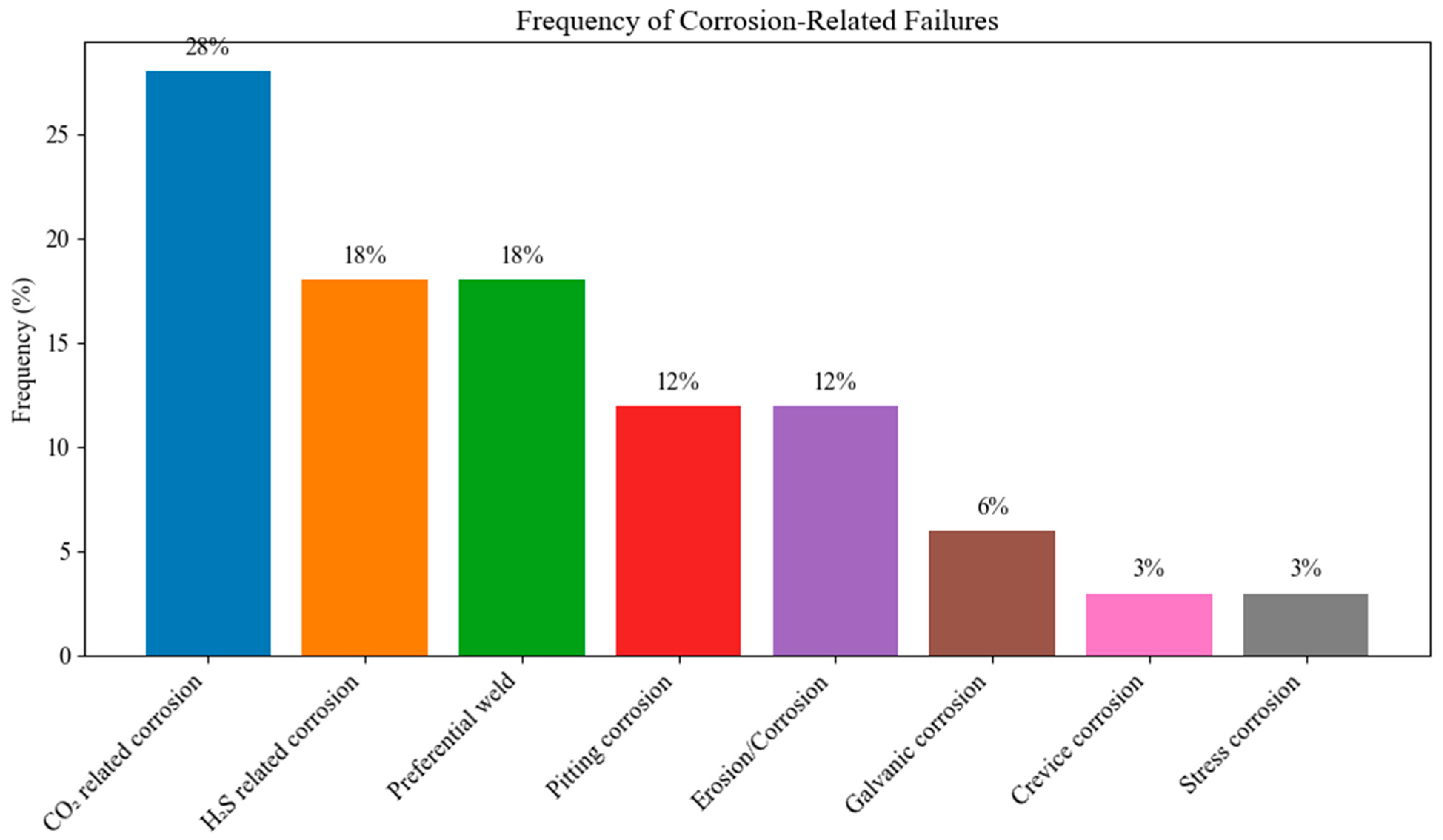
    Detection/Mitigation: Difficult to predict and diagnose. Requires specialized sampling and analysis techniques (molecular methods like quantitative PCR are improving detection). Control involves using biocides (batch or continuous), regular cleaning (pigging) to remove deposits and biofilms, and maintaining flow to prevent stagnation [154]. To understand the practical significance of these corrosion modes, Figure 13 summarizes the relative frequency of corrosion-related failures in oilfield systems. CO2-related corrosion is the leading cause, responsible for 28% of all reported corrosion failures, followed by H2S-related corrosion and preferential weld corrosion, each contributing 18%. Pitting and erosion/corrosion each account for 12%, while galvanic, crevice, and stress corrosion mechanisms collectively represent the remaining 15%. These statistics underscore that 46% of failures are due to acid gas environments, emphasizing the critical need for tailored materials selection, real-time corrosion monitoring, and targeted inhibition strategies in wells exposed to CO2-rich or sour gas conditions.
    Organic Acid Corrosion: Naturally occurring organic acids (e.g., acetic, propionic) present in some reservoir fluids can contribute to corrosion, particularly at higher temperatures and pressures, although typically less aggressive than CO2 or H2S. Their presence can also influence the pH and stability of protective scales [155].
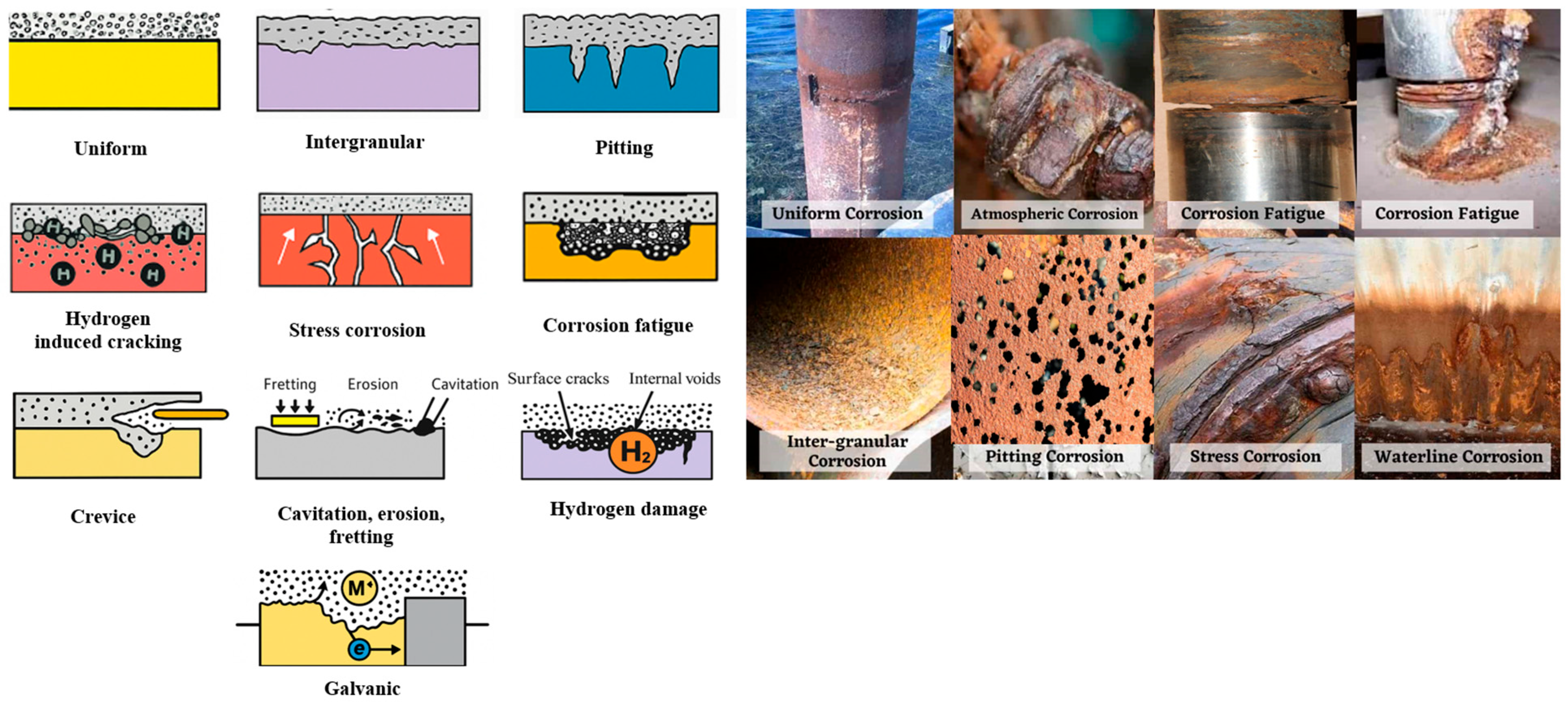
Figure 12. Comparison of corrosion types through schematic diagrams (left) and real-world field photographs (right). The illustrations show classic corrosion patterns such as uniform, intergranular, galvanic, pitting, crevice, stress corrosion cracking, hydrogen-induced damage, corrosion fatigue, and combined fretting, erosion, and cavitation. These forms are commonly encountered in oilfield operations and contribute significantly to metal loss and failure. Drawn by the authors.
Energies 18 04757 g012
Figure 13. Relative frequency of different corrosion-related failure mechanisms observed in oil and gas well systems. CO2 and H2S corrosion dominate internal degradation cases, while pitting, erosion-corrosion, and galvanic corrosion also pose significant localized threats [156]. Reproduced from [156], under the terms of the Creative Commons CC BY 4.0 license.
Energies 18 04757 g013

6.2.3. Hydrogen Embrittlement (HE) and Related Damage

Hydrogen embrittlement (HE) refers to the degradation of mechanical properties such as ductility, tensile strength, and fracture toughness resulting from hydrogen atom diffusion into steel. Once adsorbed onto the metal surface, molecular hydrogen dissociates into atomic hydrogen, which diffuses through the steel lattice and accumulates at trap sites such as grain boundaries, dislocations, or non-metallic inclusions, thereby initiating crack nucleation and leading to premature failure—particularly in high-strength steels (≥1000 MPa) [157,158]. This degradation mechanism is highly influenced by environmental and operational factors; elevated pressures and temperatures, prolonged exposure durations, and stress concentrations significantly increase susceptibility [159]. Moreover, the presence of impurities such as hydrogen sulfide (H2S) exacerbates embrittlement, while others like water vapor may have lesser effects [160].
Specific to H2 environments, diffusion of atomic hydrogen into the steel lattice reduces ductility and toughness, manifesting as HE. Simultaneously, the recombination of hydrogen atoms into H2 molecules at internal defects—such as manganese sulfide (MnS) inclusions—can generate high internal pressures. This leads to hydrogen-induced cracking (HIC), which, unlike HE, does not require externally applied stress to initiate. HIC typically results from the rupture of surrounding material due to internal pressure buildup, forming cracks that propagate through the casing. The severity and likelihood of HIC are governed by the steel’s microstructure, impurity segregation, and the presence of high-angle grain boundaries [161,162]. Crack propagation is generally intergranular, driven by micro-crack formation at multiple adjacent trap sites that coalesce under stress or further hydrogen exposure.
Hydrogen blistering (HB), a near-surface counterpart to HIC, occurs when hydrogen recombination near the steel surface forms H2 gas pockets that lift the surface layers, creating dome-like blisters. Though it may appear similar to HIC, HB is typically observed in low-strength steels or regions with localized soft zones and often coexists with HIC [162]. Due to the shared mechanisms of nucleation and propagation, HB is classified as a surface-level variant of hydrogen-induced damage.
Recent advancements have expanded our understanding of hydrogen-induced degradation beyond conventional steels, highlighting its relevance to high-entropy and medium-entropy alloys used in hydrogen storage systems. For instance, [163] demonstrated that local lattice distortion in Ti–Nb–X MEAs significantly influences hydrogen solubility and solution energy, while in high-temperature nickel-based superalloys such as Inconel-718, hydrogen diffusion can induce dislocation transformations that degrade mechanical properties at elevated temperatures [164].
Elastomer Degradation: Seals made from elastomers (used in packers, wellheads, etc.) can degrade via chemical attack (CO2, H2S, hydrocarbons, completion fluids), thermal degradation at high temperatures, explosive decompression (RGD) when pressure is rapidly released, extrusion into gaps under pressure, and mechanical wear [27]. This swelling is driven by CO2 sorption, as documented by [156], who measured significant CO2 uptake in various elastomers—up to 30% by weight in some cases—using in situ FTIR microscopy. The study highlighted that swelling is directly proportional to CO2 uptake, with typical swelling levels ranging from 15% to 30% at 15 MPa and 50 °C for common elastomers. This swelling can alter elastomer mechanical properties, leading to compromised sealing performance and increased risk of ED upon pressure drops. Additionally, elastomer chemical compatibility varies: materials like EPDM, SBR, and EVM exhibit substantial swelling due to their high chain mobility and affinity for CO2. To ensure reliable performance in CCS applications, it is necessary to use specialized, CO2-resistant, high-grade elastomers (such as specific FFKM and HNBR grades) and potentially metal-to-metal (MTM) seals in critical applications. Proper material selection and validation under representative CO2-rich conditions are crucial to mitigating these risks and maintaining long-term well integrity.

6.3. Thermal and Pressure Cycling Effects

Well operations inevitably impose mechanical and thermal stresses on the casing-cement-formation system. While initial stresses are applied during construction (casing running, cementing), these operational stresses accumulate over time and can initiate or exacerbate mechanical damage (cracking, debonding) that degrades integrity [165]. The structural impact of internal pressure variation on casing integrity can be quantitatively assessed through finite element modeling [166] Click or tap here to enter text.. Figure 14 shows the evolution of Von Mises stress under three pressure scenarios during hydraulic fracturing: (a) residual stresses present even at zero internal pressure due to geometric irregularities, (b) stress concentration initiating at 60 MPa as hoop stress builds up, and (c) severe triaxial stress amplification at 120 MPa, leading to plastic deformation and ovalization. These results highlight how pressure cycling, especially in high-pressure fracturing or gas storage wells, can induce casing distortion and initiate long-term failure if not accounted for in design.
Pressure Cycling: Repeated cycles of high and low pressure inside the casing (e.g., during production fluctuations, batch injection, cyclic steam stimulation—CSS, pressure testing, stimulation treatments, gas storage injection/withdrawal cycles) cause the casing to repeatedly expand and contract radially and axially. This cyclic loading fatigues the bond at the casing-cement interface and can initiate or propagate micro-annuli and cracks within the cement sheath, leading to progressive degradation of the hydraulic seal over time [10,164]. Cement fatigue under cyclic loading can cause microfractures that compromise the hydraulic seal.
Thermal Cycling: Similar to pressure cycling, repeated changes in temperature (e.g., production startups/shutdowns, steam injection cycles in thermal recovery wells, hot fluid circulation during cleanouts, injection of cold fluids like CO2 or gas) cause significant differential expansion and contraction between the casing (which typically has a higher thermal expansion coefficient than cement and formation rock) [168]. This induces cyclic shear and tensile stresses at the interfaces and within the cement, which are highly damaging to bond integrity and can cause fatigue cracking. HPHT wells, geothermal wells, thermal EOR wells (steam injection), and gas storage wells (due to Joule–Thomson cooling/heating during cycles) are particularly prone to severe thermal cycling effects and associated cement damage [169]. Thermal cycling not only induces interface and cement damage but also directly weakens casing materials. Figure 15 presents the variation in yield strength of common casing grades (J55, N80, P105, P110) with increasing temperature. The data clearly show that elevated temperatures—especially beyond 300 °C—significantly reduce mechanical strength, with high-strength steels like P110 experiencing the most pronounced degradation. This trend underscores the importance of thermal stability in material selection for geothermal and thermal recovery wells, where sustained or repeated high-temperature exposure is expected. Thermal expansion and contraction during operational heating and cooling cycles not only affect bulk casing properties but also induce significant mechanical stresses at casing connections. Figure 16 illustrates the thermal stress path of a casing string during heating and cooling. As temperature increases, axial compression builds until the yield point is reached—at which point plastic deformation or even buckling of the casing or connector may occur. Upon cooling, the casing undergoes axial tension, which can exacerbate thread damage or initiate separation at the casing-coupling interface, particularly in high-temperature or cyclic service wells.

6.4. Erosion and Wear

The physical removal of material from wellbore components due to flowing fluids and entrained solids can significantly impair integrity.
  • Erosion: Erosion is the physical removal of material from a surface by the mechanical action of flowing fluids, especially those containing solid particles (e.g., sand produced from the reservoir, proppant flowback after fracturing, solids in drilling mud or injection water) [172,173,174].
    Mechanism: High-velocity fluid impingement or abrasive action of particles wears away the metal surface. Typically, occurs at points of high turbulence, flow direction change (bends, elbows, tees), restrictions (chokes, valves, perforation tunnels), or where flow impinges on a surface.
    Factors: Rate increases significantly with flow velocity (often exponentially), particle concentration, particle size/hardness/shape, and impingement angle. High flow rates in production tubing or near perforations are common areas for erosion. Erosive wear from repeated coiled tubing (CT) operations is a significant contributor to wellbore damage, especially when low-grade CT is used or when the number of runs per well is high. Figure 17 compares the number of wells with groove damage for low- and high-grade CT materials. The chart shows that although high-grade CT is more commonly used, it is also associated with a greater number of runs per well and a higher incidence of groove damage—highlighting the cumulative mechanical impact of repeated CT deployment on casing integrity.
  • Erosion-Corrosion: This is a highly aggressive synergy where erosion and corrosion act together, resulting in metal loss rates far exceeding the sum of erosion and corrosion acting alone [175].
    Mechanism: The mechanical action of erosion (or even flow shear stress alone, sometimes called flow-accelerated corrosion) continuously removes any protective corrosion product layers (scales like FeCO3, FeS, or passive films) from the metal surface. This prevents the formation or reformation of these layers, constantly exposing fresh, active metal underneath to the corrosive environment, dramatically accelerating the overall metal loss rate.
    Occurrence: Common in high-velocity production streams containing both solid particles (sand) and corrosive species (CO2, H2S, organic acids). Particularly aggressive at points of high turbulence or impact (chokes, bends, valves, production nipples, near perforations).
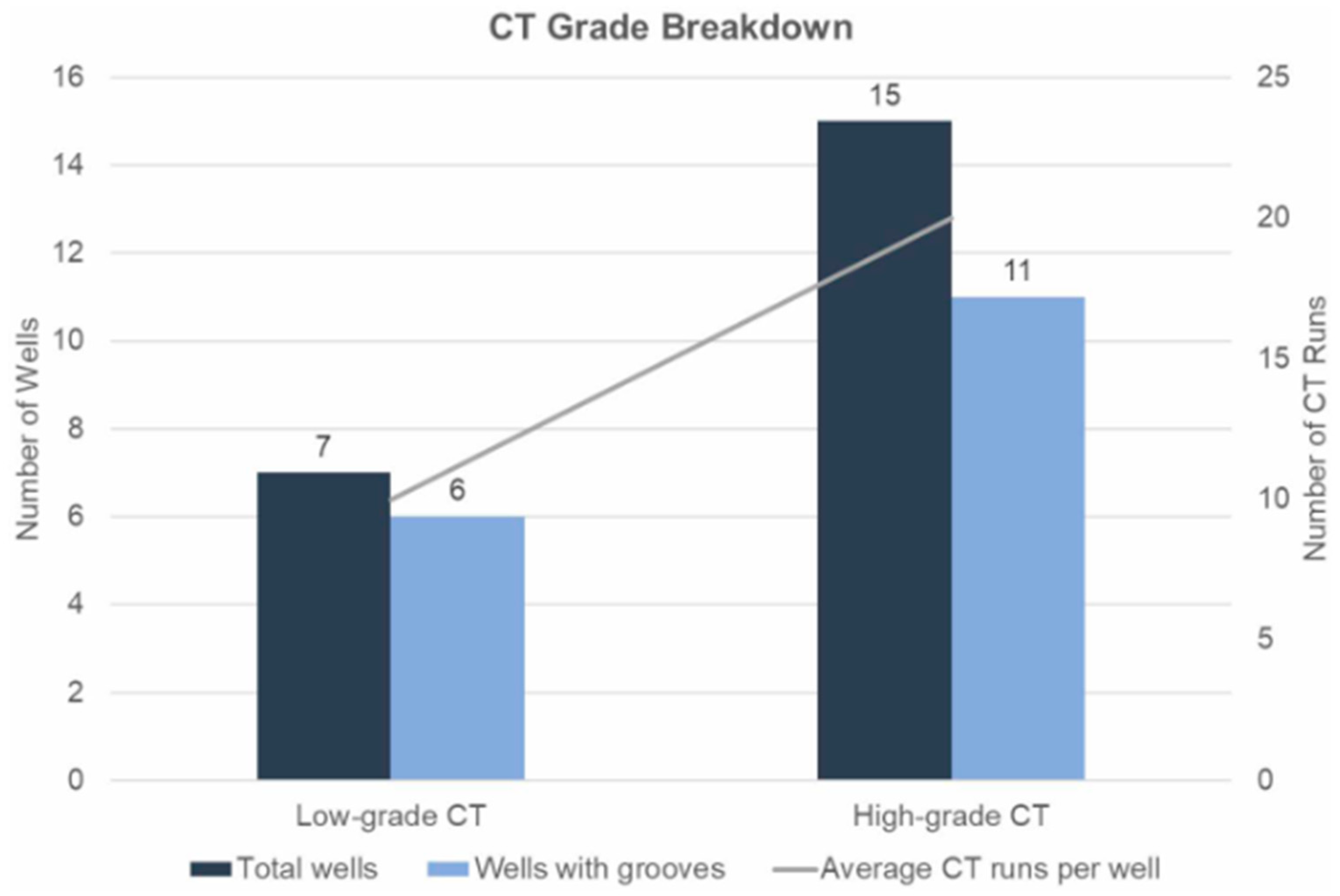
Figure 17. Number of wells and occurrences of groove damage associated with different coiled tubing (CT) grades. The left bars represent total wells and wells with grooves for low-grade CT, while the right bars show the same data for high-grade CT. The line indicates the average number of CT runs per well, showing a clear correlation between CT grade, number of runs, and wellbore groove damage [176]. Reproduced with permission from [176].
Energies 18 04757 g017

7. Cement Integrity Innovations

Given that cement sheath failure is a leading cause of well integrity loss, driving issues like SCP and loss of zonal [12,51], considerable effort has been invested in developing innovative cement systems beyond traditional Portland cement. These innovations aim to enhance mechanical resilience, improve chemical stability, and even introduce self-repairing capabilities.
A major focus has been on improving the mechanical properties of cement to better withstand downhole stresses. Traditional Portland cement is inherently brittle and prone to cracking under the tensile and shear stresses induced by pressure and temperature cycling. To counteract this, flexible cement systems have been developed. These typically incorporate polymers or elastomeric particles (e.g., rubber) into the cement slurry [10,177]. The addition of these materials lowers the Young’s modulus and increases the ductility (or reduces the brittleness) of the set cement, allowing it to deform more readily without fracturing when subjected to casing expansion/contraction or formation movement. Cement sheath failures arise from a combination of poor placement, suboptimal cement properties, and challenging wellbore conditions. Figure 18 illustrates the most common mechanical causes of cement degradation—such as cement channels, eccentric annuli, and thermal/pressure cycling—as well as the resulting leakage pathways. These include micro-annuli, radial cracks, interfacial debonding, and longitudinal fractures, each compromising zonal isolation and enabling fluid migration along the wellbore [178]. While this often comes with a reduction in compressive strength, the increased toughness can prevent crack propagation [179]. However, incorporating high loadings of elastomers can increase slurry viscosity, potentially complicating placement [180]. Other modified cement systems utilize alternative binders like calcium sulfoaluminate (CSA) cements, which can offer rapid strength development and potentially better resistance to sulfate attack, or geopolymers derived from activating industrial byproducts (like fly ash or slag), which may exhibit superior chemical stability in acidic or CO2-rich environments. Nanomaterials, such as nanosilica or carbon nanotubes, are also being explored as additives to enhance mechanical properties and reduce permeability at the micro-scale [17].
Another exciting frontier is self-healing cement, designed to autonomously repair damage like microcracks as they form, thereby restoring the cement’s sealing ability and extending its functional life [181,182]. Several mechanisms are being explored: incorporating microencapsulated healing agents (e.g., epoxy resins, sodium silicate) that rupture when a crack propagates, releasing the agent to fill the void; utilizing expansive minerals or crystalline additives that react with intruding fluids (like water or CO2) to precipitate and block the crack path; or leveraging and enhancing the natural autogenous healing capacity of cement through controlled hydration reactions. Some elastomer-modified cements offer a form of self-sealing where the elastomeric particles swell upon contact with hydrocarbons flowing through a crack, potentially blocking the pathway [177,183]. While promising, the long-term effectiveness and reliability of self-healing systems under diverse downhole conditions require further validation [133].
Improving the integrity of the formation–cement–casing interfaces remains critical, as these are often the weakest links and primary conduits for leakage [184]. Research continues optimizing slurry properties (e.g., shrinkage reduction, improved fluid loss control) and placement techniques (e.g., efficient mud removal using advanced spacers, enhanced casing centralization) to achieve better initial bonding and minimize the formation of microannuli [185,186]. Advanced modeling of interface behavior using numerical methods like FEA helps predict debonding and shear failure under operational loads and guides the development of cement systems with improved interfacial toughness and bonding characteristics [18,187,188]. The casing-cement interface is especially susceptible to mechanical damage under operational pressures. Figure 19 presents laboratory observations of cement sheath micro-annuli formation under increasing internal casing pressures (70 MPa, 80 MPa, 90 MPa). These images demonstrate how internal pressure during hydraulic fracturing can progressively degrade interfacial bonding, widening micro-annuli that severely impair hydraulic isolation and elevate the risk of sustained casing pressure or gas migration [189]. These innovations collectively aim to create more durable and reliable cement barriers capable of withstanding the rigors of the downhole environment throughout the well’s lifecycle, systematically assessing and managing cement integrity risks. Structured tools like risk matrices and bow-tie diagrams are increasingly applied. Figure 20 combines a cement failure risk matrix and a bow-tie diagram to visualize how different failure modes—such as cement channeling, microannuli formation, shrinkage, and placement errors—map against their likelihood and potential consequences. The matrix highlights high-risk pathways (e.g., frequent microannulus formation with zonal isolation loss), while the bow-tie diagram distinguishes between preventive (e.g., mud removal, slurry design) and mitigative (e.g., annular pressure monitoring, emergency shut-ins) barriers to manage threats before and after failure. This dual approach supports more proactive and resilient well integrity planning.

Cement Setting and Hydration

Once placed in the annulus, the cement slurry undergoes hydration, a chemical reaction with water that transitions it from a fluid to a solid, load-bearing material [188]. This process generates heat (heat of hydration) and develops compressive strength, tensile strength, and low permeability over time. The rate of strength development is primarily influenced by downhole temperature, pressure, and the cement/additive formulation [190,191].
  • Waiting-on-Cement (WOC) Time: This is the minimum period required for the cement to develop adequate compressive strength before proceeding with subsequent operations (e.g., nippling down the BOP, drilling out the shoe track, or perforating). WOC time depends on the slurry design, wellbore temperature, and the operational strength requirement—such as supporting casing weight, ensuring zonal isolation, or enabling pressure testing. Reference [192] provides standardized procedures for testing and reporting the compressive strength of well cements but does not prescribe a specific minimum threshold. In practice, thresholds such as 50 psi (0.34 MPa) for basic mechanical support or 500 psi (3.45 MPa) for formation integrity tests and leak-off tests are commonly used based on operational or regulatory requirements.
  • Strength Development: Cement strength continues to increase beyond the minimum WOC time for days or weeks. Final strength and durability depend on full hydration and resistance to degradation over time.
  • Bond Strength: The strength of the hydraulic and mechanical bond between the set cement and the casing and formation is critical for zonal isolation and structural support. Bond strength develops as the cement sets and is heavily influenced by the effectiveness of mud removal, centralization, and shrinkage control during placement.
Achieving a successful primary cement job, characterized by complete annular fill across zones of interest, good bonding to both casing and formation, adequate compressive strength, low permeability, and freedom from leak paths, is fundamental to establishing durable well integrity from the start. Failures in primary cementing are latent defects that often lead to integrity problems like SCP years after the well is put on production and are typically difficult and expensive to remediate later in the well’s life, highlighting the importance of getting it right during construction. The vulnerability of the cement to gas migration is most pronounced during the transition time, when the slurry changes from a pumpable fluid to a semi-solid with measurable gel strength. This period is marked by a decline in hydrostatic pressure as hydration progresses, potentially allowing formation gas to enter the annulus before the cement develops sufficient resistance. Figure 21 illustrates this critical window, showing the relationship between hydrostatic pressure, static gel strength, and compressive strength development over time. It underscores the importance of minimizing transition time and designing slurries that rapidly build gel strength to resist gas intrusion during this vulnerable period.

8. Geomechanics of the Wellbore System

The mechanical interaction between the wellbore structure (casing and cement) and the surrounding geological formation—governed by the principles of geomechanics—is fundamental to understanding and maintaining well integrity [18,87]. Drilling a well significantly alters the in situ stress state of the rock by removing supporting material, creating stress concentrations around the borehole [194]. Subsequent operations, particularly fluid injection or production, further modify the stress field by changing pore pressures and temperatures within the formation [59]. Understanding the stress path—the evolution of these stresses over time—is critical for predicting potential rock failure (such as borehole instability during drilling, sanding during production, or induced fracturing during injection) and assessing the resulting loads imposed on the wellbore casing and cement sheath.
Wellbore stability during drilling is a primary geomechanical concern; insufficient mud weight can lead to shear failure and collapse of the borehole wall, while excessive mud weight can induce tensile fractures and cause fluid losses [7,194]. During injection operations (waterflooding, waste disposal, CO2/H2 storage, hydraulic fracturing), the increase in pore pressure reduces the effective stress acting on the rock matrix. If this reduction is significant, it can trigger shear slip along pre-existing planes of weakness like faults or natural fractures, potentially causing casing deformation or shear if the fault intersects the wellbore [195]. If the injection pressure exceeds the formation’s fracture gradient, new hydraulic fractures will be created, which is the basis of stimulation but can also pose risks if fractures propagate out of the target zone or compromise barrier integrity.
Large-scale formation deformation associated with pressure changes, such as reservoir compaction due to fluid withdrawal or formation uplift due to large-volume injection, can impose substantial axial, bending, and shear loads on the well structure, potentially leading to casing buckling, collapse, or tensile failure [196].
The mechanical integrity and bonding quality of the interfaces between the casing and cement, and between the cement and the rock formation, are crucial for zonal isolation and overall system stability. Strong bonding helps transfer stresses effectively and prevents the formation or propagation of microannuli, which act as primary leakage pathways [12,197]. Geomechanical models often incorporate constitutive laws and failure criteria (e.g., Mohr–Coulomb, Drucker–Prager) to predict when the rock or cement will yield or fail under the complex triaxial stress conditions present around the wellbore [18,59]. These analyses help define safe operating windows for drilling mud weights and injection pressures to maintain both borehole stability and barrier integrity. The presence of geological discontinuities like faults and fractures must be carefully considered in well design and operational planning, as they represent potential zones of weakness and fluid migration pathways. To better understand the mechanical response of the cement-casing system under fault activation scenarios, numerical simulations have been conducted using von Mises stress distributions to evaluate the effect of varying shear cement strengths. Figure 22 illustrates how lower cement shear strength increases the risk of mechanical failure when the fault plane is reactivated during injection operations. Similarly, the integrity of the overlying caprock is paramount for geological storage applications, and geomechanical assessments are needed to ensure that injection operations do not compromise its sealing capacity [3].

9. Digital Twin and Real-Time Integrity Monitoring

The ongoing digital transformation across industries is profoundly impacting well integrity management, with the concept of the Digital Twin emerging as a powerful integrating paradigm [1]. A digital twin, in the context of well integrity, functions as a dynamic, synchronized virtual representation of a physical well asset and its surrounding environment [199,200]. Its core architecture typically comprises several key components: a network of sensors deployed downhole and at the surface to capture real-time operational and environmental data; a robust data transmission infrastructure (wired or wireless); a cloud or edge computing platform for efficient data storage, processing, and management; sophisticated physics-based simulation engines capable of modeling wellbore behavior; and advanced analytical modules, often incorporating machine learning (AI) and artificial intelligence (AI), to interpret data and predict future performance [1].
The cornerstone of the digital twin is the seamless integration of real-time sensor data. Continuous streams of information from downhole pressure and temperature gauges, distributed sensing systems like distributed temperature sensing (DTS) and distributed acoustic sensing (DAS), permanently installed strain gauges, acoustic monitors, corrosion probes, and surface sensors measuring flow rates, pressures, and fluid compositions provide an unprecedentedly detailed and timely view of the well’s operational status and physical condition [20,201,202]. This constant influx of data allows the digital twin to accurately mirror the current state of the physical asset, moving beyond the limitations of periodic inspections towards continuous, dynamic surveillance.
The transformative potential of the digital twin lies in its ability to intelligently couple this real-time data with sophisticated simulation models. The virtual replica can run complex simulations—often incorporating coupled thermo-hydro-mechano-chemical (THMC) effects—to analyze the well’s response under current operating conditions and, crucially, to predict its behavior under future scenarios or proposed operational changes [203,204,205]. This allows operators to virtually assess stress distributions in casing and cement, predict remaining fatigue life, model corrosion rates or cement degradation, evaluate the risk of sand production, simulate the consequences of changing injection parameters, and test intervention strategies before implementing them in the field.
Furthermore, by integrating machine learning (ML) and artificial intelligence (AI) algorithms, digital twins evolve from purely diagnostic tools into powerful predictive maintenance platforms [206,207,208]. ML models can be trained on historical and real-time data to identify subtle anomalies or complex patterns that may precede failure, predict the remaining useful life (RUL) of critical components, optimize inspection and maintenance schedules based on predicted risk, and automatically generate alerts for potential integrity issues, enabling proactive intervention [20,25]. Early case studies and applications, particularly in high-value or high-risk operations such as carbon capture and storage (CCS), deepwater production, and geothermal energy extraction, are actively demonstrating the significant value of digital twins in enhancing operational efficiency, improving safety, managing long-term integrity risks, and providing robust assurance of containment through improved monitoring, diagnostics, and predictive capabilities

9.1. Digital Twin Technologies in Well Integrity Management

Digital twin technology has emerged as a transformative tool in well integrity management, integrating data streams, real-time monitoring, and physics-based simulations to provide a comprehensive view of well life [200,209]. A Digital Twin, in this context, is a dynamic virtual representation of a physical well and its surrounding geological and operational environment. It integrates both static and dynamic data to simulate and assess well performance and integrity across its entire lifecycle—from construction to abandonment [199].
A robust digital twin architecture typically consists of the following:
  • Static data: as-built well designs, casing and tubing specifications, formation properties, material properties, well logs (e.g., caliper logs for cement design), and cementing job parameters.
  • Dynamic data: sensor-derived real-time pressure, temperature, and flow rates, DTS/DAS readings, casing load records during drilling, cement bond logs, pressure test outcomes, corrosion monitoring data, and operational telemetry [20].
  • Physics-based models: simulating multiphase flow, heat transfer, THMC (thermo-hydro-mechanical-chemical) stresses, corrosion kinetics, and casing-cement-rock interactions [204,210].
  • AI/ML modules: predictive maintenance tools, anomaly detection systems, remaining useful life (RUL) forecasts, and scenario simulations [207,208].
  • Visualization platforms: interactive dashboards and 3D models presenting KPIs, alerts, and real-time diagnostics for field engineers and asset managers [209].
When fully integrated, digital twins allow operators to evaluate well integrity status, simulate leak evolution, predict casing fatigue, assess the risk of SCP (sustained casing pressure), model cement degradation, and test remediation scenarios—all without physical intervention [200,211]. This facilitates safer, cost-effective operations, particularly in high-stakes applications like underground gas storage (UGS), CCS, deepwater wells, and geothermal systems.
Lifecycle Integration for Well Integrity:
Digital twins must ingest and synthesize data across all well phases:
  • Design/Construction: casing design, makeup torque values, steel/cement properties, centralizer placement, and pre-job simulations.
  • Drilling and Cementing: caliper logs for hole geometry, real-time ECDs, cement slurry density/yield, pressure test logs, and cement bond log evaluations.
  • Operations: downhole sensors capturing pressure/temperature, load histories on casing and tubing, periodic NDT/inspection reports, and intervention history.
  • Abandonment: plug placement verification, pressure isolation tests, and long-term monitoring setups.
This end-to-end data capture, integrated with AI, enables the digital twin to continuously learn, simulate evolving failure scenarios, and improve decision-making accuracy [25,206].

9.2. Technical Challenges and Readiness of Digital Twins

Despite their promise, several technical and operational challenges remain:
  • Data interoperability: integrating diverse data types (e.g., DAS, E-log, cement bond logs) across vendors and lifecycle stages.
  • Model calibration and validation: real-world conditions often deviate from assumptions in simulations, requiring regular updates and data assimilation.
  • Sensor reliability and coverage: downhole sensors are expensive and can fail, limiting spatial and temporal resolution.
  • AI interpretability: black-box predictions from ML can be difficult to explain or trust without physical validation or explainable AI.
  • Cybersecurity and data governance: securing massive data flows and defining access across stakeholders is critical, especially for cross-operator collaborations.
Technology maturity also varies.
  • Low for fully autonomous digital twins with real-time control capabilities.
  • Moderate for predictive integrity tools and scenario-based simulation.
  • High for dashboard-based visualization and data aggregation platforms [202].

10. Smart Monitoring and AI for Integrity

Building upon the integrated framework of digital twins, smart monitoring represents the application of advanced sensing technologies combined with artificial intelligence (AI) and machine learning (ML) to achieve deeper diagnostic insights, automated analysis, and enhanced decision support specifically for well integrity assurance [1,25]. A fundamental principle is data fusion, which involves algorithmically combining information from a multitude of diverse sources to create a more holistic and accurate assessment of the well’s condition than any single data stream could provide. This includes integrating real-time downhole sensor data (e.g., pressure, temperature, DTS, DAS, strain, corrosion sensors), surface measurements (e.g., wellhead pressures, flow rates, fluid samples), periodic diagnostic logs (e.g., ultrasonic imaging, electromagnetic thickness tools, caliper logs), intervention records, and historical operational data [212,213,214].
AI and ML algorithms are the engines driving smart monitoring. Various ML models are being developed and deployed for specific integrity tasks. For instance, supervised learning models can be trained to predict corrosion rates based on fluid properties, temperature, pressure, and flow regimes [22,215,216]; estimate remaining fatigue life for casing or connections using operational history and stress modeling; or classify the type and severity of detected integrity issues, such as distinguishing between different sources of SCP. Unsupervised learning techniques can identify complex anomalies or subtle deviations from normal operating behavior in sensor data streams, potentially signaling incipient leaks or barrier degradation before they become critical. ML is also enhancing the interpretation of traditional logging data; for example, algorithms can improve the accuracy of through-tubing cement bond evaluation or identify corrosion patterns from electromagnetic logs [215,216].
The ultimate vision for smart monitoring involves moving towards real-time failure alerts and potentially automated decision-making for certain integrity management [217,218]. AI systems could automatically flag concerning trends, trigger alarms based on predefined risk thresholds, recommend specific diagnostic tests, or even initiate automated shut-in procedures in critical situations. This automation aims to reduce response times, optimize resource allocation by focusing human expertise on the most complex problems, and improve overall system reliability. However, realizing this vision requires addressing challenges related to data quality and availability, algorithm robustness and explainability (especially for safety-critical decisions), cybersecurity of connected systems, and building operational trust in automated recommendations [219,220]. Despite these hurdles, AI-powered smart monitoring offers a transformative potential to significantly enhance early threat detection, improve diagnostic accuracy, enable proactive interventions, and ultimately elevate the standards of well integrity management.

Integration Monitoring Tools

The toolbox for assessing well integrity involves both periodic and continuous methods. Periodic wireline logging remains a standard practice, utilizing tools like cement bond logs (CBLs) and variable density logs (VDLs) to infer cement bond quality from acoustic signal attenuation, although interpretation can be complicated by factors like microannuli, casing eccentricity, lightweight cements, or gas-cut cement [221,222,223]. Ultrasonic imagers (USI/UCI/CET) provide higher-resolution mapping of the cement-casing interface and casing condition but can also face interpretational challenges [224]. Other periodic logs include radioactive tracer surveys (RATSs) to track fluid movement, caliper logs for internal diameter measurements (detecting wear or deformation), and electromagnetic corrosion logs capable of assessing metal thickness loss even behind multiple casing strings [225,226,227]. Dynamic conditions are assessed using production logging tools (PLTs), temperature logs (TLs), and spectral noise logs (SNLs), which analyze flow profiles, temperature anomalies, or acoustic noise signatures to detect leaks or crossflow [228]. Pulsed-neutron logs are valuable for identifying fluid types (e.g., water entry) behind casing by detecting characteristic gamma rays [229]. Surface pressure testing of annuli remains a fundamental method for detecting leaks manifesting as SCP, though it does not pinpoint the leak source [7,37]. Advancements include permanently installed sensors and fiber-optic systems (DTS/DAS), providing continuous temperature and acoustic data along the wellbore for real-time monitoring of leaks, fluid levels, valve operations, and potentially cement integrity [201,202]. Soft sensors, using algorithms to infer parameters where physical sensors are absent, are also emerging, particularly for legacy wells. The use of advanced logging techniques—combining mechanical, acoustic, thermal, and electromagnetic measurements—offers a powerful means of diagnosing well integrity issues. Figure 23 presents three critical examples demonstrating how different log types detect casing deformation, fluid leaks, and corrosion in multi-barrier systems. High-resolution ultrasonic tools are now also used for detailed inspection of downhole components like DHSVs [230]. Integrating ML with these techniques further refines diagnostic capabilities.

11. Storage Integrity in CO2, H2, and CH4 Injection Wells

The geological storage of gases—driven by climate change mitigation (CO2) and energy system decarbonization (H2, potentially CH4 with CCS)—presents unique and demanding challenges for long-term well integrity, often exceeding those encountered in traditional hydrocarbon production. Wells used for storage must maintain sealing integrity not just for operational decades, but potentially for centuries or millennia, under exposure to specific fluids and often cyclic operating conditions [232,233,234].
CO2 storage wells face a primary challenge from the inherently corrosive nature of wet CO2 (supercritical or gaseous), which forms carbonic acid upon contact with water [11,135]. This acidic environment aggressively attacks conventional Portland cement, leading to carbonation reactions that alter the cement matrix, dissolving key hydration products (calcium hydroxide, C-S-H) and increasing porosity and permeability over time [235,236]. This degradation can create leakage pathways along the wellbore, potentially leading to loss of stored CO2 and SCP issues [236,237]. Similarly, carbonic acid causes significant corrosion of carbon steel casing, necessitating the use of expensive corrosion-resistant alloys (CRAs) or robust corrosion management programs involving specialized coatings and monitoring [17,238]. Elastomers used in packers and seals are also susceptible to degradation (swelling, RGD) in high-pressure CO2 environments [23].
Underground hydrogen storage (UHS) introduces a different set of material compatibility challenges stemming from hydrogen’s unique properties: its small molecular size, high diffusivity, and chemical reactivity. Steel components are vulnerable to hydrogen embrittlement (HE), where diffused hydrogen reduces the metal’s ductility and fracture toughness, particularly in high-strength steels [239,240]. Hydrogen can also cause HIC and blistering through internal pressure buildup from recombined H2 molecules. The interaction of hydrogen with cement is complex and not fully understood; potential concerns include chemical reactions altering cement mineralogy and structure, and increased permeability due to hydrogen diffusion or reaction byproducts [26,241,242]. Experimental results have been varied, indicating the need for more long-term, representative testing [243,244,245]. Microbiologically influenced corrosion (MIC) is a significant concern, as subsurface microbes (like SRBs) can utilize stored hydrogen and produce highly corrosive H2S, which exacerbates steel embrittlement and can also attack cement [246,247]. Elastomers also face degradation risks in high-pressure hydrogen. These complex degradation pathways are illustrated in Figure 24, which synthesizes the primary mechanical and chemical threats to well integrity in hydrogen storage and extraction operations.
Natural gas storage (UGS), often utilizing depleted reservoirs or salt caverns, primarily contends with the effects of high-pressure cyclic loading due to seasonal injection and withdrawal [9,10]. These repeated pressures and associated temperature cycles can induce fatigue damage in casing, connections, and cement sheaths over many years of operation [57]. If the stored gas contains impurities like CO2 or H2S, or interacts with residual formation water, corrosion remains a concern [17,22]. Wells in salt caverns face additional geomechanical challenges from salt creep, which can impose significant non-uniform closure stresses on the casing, potentially leading to collapse or shear failure [248,249,250]. Salt dissolution can also create voids and stability issues.
For all storage applications, rigorous site characterization, including assessment of reservoir properties and caprock sealing capacity, is crucial. Injection operations must be carefully designed and monitored to stay within safe pressure limits that avoid compromising the caprock or reactivating faults. Risk mapping, particularly identifying legacy wells penetrating the storage complex, is essential [251]. Cross-learning between CCS, UHS, and UGS projects is vital for developing robust materials qualification protocols, long-term monitoring strategies, and reliable P&A designs capable of ensuring containment over the required storage duration. A detailed analysis of leakage incidents in underground natural gas storage (UGS) wells is presented in Figure 25, providing insight into failure frequency, contributing components, and causal factors across different reservoir types.
  • Enhanced Oil Recovery:
Many techniques used in enhanced oil recovery (EOR) processes also impose significant integrity stresses, sharing similarities with storage operations. Water and gas injection for pressure maintenance or sweep improvement can lead to fluid migration, leakage, and formation stress changes (uplift/subsidence) that can induce casing strain or reactivate faults [253,254]. Thermal recovery methods (steam drive, CSS, SAGD) inject high-temperature steam (often 220–350 °C), inducing severe thermal stresses that cause casing expansion/contraction, buckling, connection fatigue, and cement sheath degradation [253,255]. Operating stresses frequently exceed the elastic limits of standard casing material [256,257]. Maintaining long-term zonal isolation under these harsh thermal and pressure cycles is a major challenge [258]. Historical data from thermal EOR operations—particularly cyclic steam stimulation (CSS) and steam-assisted gravity drainage (SAGD)—reveal trends in integrity failures and the most common remediation strategies, as illustrated in Figure 26. The top panel illustrates a significant rise in reported failures from the 1990s to the early 2000s, coinciding with the widespread adoption of thermal recovery technologies. A notable decline in failures post-2010 likely reflects advancements in well design, materials, and monitoring practices. The bottom panel details the distribution of remediation approaches, with casing patching (21%), cemented liners (17%), and production zone repairs (17%) representing the most common interventions. These findings highlight the repetitive and thermally driven nature of well integrity degradation and underscore the importance of proactive design, thermal stress mitigation, and timely intervention strategies to maintain long-term wellbore performance. Sand production in EOR injection wells in unconsolidated formations can also lead to erosion and injectivity loss [259,260]. As shown in Figure 27, sustained high injection pressures have been empirically linked to increased casing damage incidents, underscoring the critical role of pressure regulation in maintaining wellbore integrity.

12. Legacy and Orphaned Wells

A looming and globally significant challenge for subsurface management and environmental protection is the vast inventory of legacy wells (inactive wells where the operator may be known but potentially defunct or financially unable to manage liabilities) and orphaned wells (inactive wells with no identifiable or solvent responsible party). Millions of such wells exist worldwide, many drilled decades ago using outdated technologies and abandonment standards that fall far short of modern requirements for ensuring long-term containment [15]. These wells represent significant integrity risks, acting as potential preferential leakage pathways for subsurface fluids—notably methane (a potent greenhouse gas) emissions to the atmosphere, or brine and hydrocarbon migration contaminating freshwater aquifers [5,15].
Common integrity deficiencies in these wells include severely corroded or degraded casing, incomplete or deteriorated cement in critical annular spaces (sometimes cement was omitted entirely in certain sections), failed or inadequate plugs (e.g., short plugs, degraded materials, plugs set in uncased sections), and often, poor or missing documentation regarding well construction, geological location, and abandonment procedures [262,263,264]. Identifying the specific leakage pathways and quantifying emission rates from these wells can be extremely challenging and costly, often requiring specialized diagnostic tools like downhole cameras, advanced logging suites (acoustic, temperature, noise), and surface flux measurements.
Developing and deploying effective, reliable, and cost-efficient retrofit technologies for re-entering and properly plugging or repairing these wells to ensure long-term sealing integrity is a critical area of ongoing research, development, and field application [265]. This might involve milling out old plugs, setting new cement or alternative barrier materials, or deploying specialized sealing systems. The immense scale of the problem necessitates prioritization strategies based on risk assessment (considering factors like proximity to populations or water resources, potential emission rates, and condition) and efficient deployment of resources.
The presence of numerous legacy and orphaned wells poses a major hurdle for the future utilization of the subsurface, particularly for large-scale CO2 and H2 storage projects [266,267]. Any potential storage site must undergo meticulous screening to identify all existing well penetrations within the storage complex and the surrounding area. The integrity status and potential leakage risk associated with each legacy well must be rigorously assessed. In many cases, extensive and costly re-abandonment campaigns to bring these wells up to modern standards will be necessary before storage operations can safely commence, representing a significant component of overall project cost and risk. Effectively addressing the global legacy and orphaned well challenge is therefore crucial not only for mitigating existing environmental liabilities but also for enabling the safe and responsible deployment of future subsurface energy technologies. As illustrated in Figure 28, methane emissions from abandoned wells vary widely across regions, with unplugged wells consistently showing significantly higher emission rates, highlighting the urgent need for improved legacy well management and sealing practices.

13. Simulation Tools and Integrity Modeling

Given the inherent difficulty in directly observing and measuring complex downhole conditions and material degradation processes over long timescales, numerical simulation has become an indispensable tool in the field of well integrity [269]. Modeling allows engineers and researchers to investigate stress states, predict material responses, simulate fluid flow through potential leak paths, evaluate the impact of operational parameters, and assess the long-term performance of well barrier systems under various scenarios.
Finite element analysis (FEA) is arguably the most widely used technique for analyzing the mechanical integrity of the wellbore system [18,24]. Using software platforms like ABAQUS, ANSYS, CMG, or COMSOL Multiphysics, engineers can build detailed models incorporating the geometry and material properties of the casing, cement sheath, and surrounding rock formations. FEA allows for the simulation of complex stress distributions arising from in situ stresses, drilling, cementing, thermal loads, pressure cycling, and external loads (e.g., formation movement, riser forces) [9,18]. It can be used to predict casing deformation modes like buckling, collapse, and ovality [103,118], evaluate stress concentrations at connections or perforations [270], assess fatigue life under cyclic loading, model the initiation and propagation of cracks within the cement sheath, and investigate the influence of defects like cement voids or poor bonding on overall system response [83].
For assessing risks associated with chemical degradation, geochemical modeling tools are essential [241,242]. Software like PHREEQC or TOUGHREACT simulates equilibrium and kinetic reactions between fluids (formation water, injected CO2, H2) and solid phases (cement minerals, steel) [271,272]. These models can predict the long-term alteration of cement mineralogy due to carbonation or sulfate attack [135,235], estimate changes in porosity and permeability resulting from these reactions, model casing corrosion rates under specific fluid compositions and temperatures [17,146], and investigate potential reactions between hydrogen and cement components in UHS scenarios.
Recognizing that many well integrity problems involve the complex interaction of multiple physical processes, multi-physics simulation platforms (such as COMSOL Multiphysics or integrated workflows coupling different specialized codes) are increasingly important [273,274]. These allow for coupled thermo-hydro-mechano-chemical (THMC) modeling, capturing critical feedback like the effect of temperature changes on stress and reaction rates, the influence of stress on permeability and fluid flow, the impact of chemical reactions on mechanical properties, and the transport of reactive species by fluid flow [275]. Such integrated models are crucial for realistically simulating phenomena like thermally induced cement cracking, stress-dependent leakage through microannuli, corrosion under flow, and the geomechanical response to large-scale fluid injection or [9,18].
These advanced simulation tools provide invaluable support for optimizing well design (e.g., casing dimensions, cement properties), defining safe operating envelopes, evaluating the long-term performance of novel materials or barrier concepts, conducting sensitivity studies to identify critical parameters, performing quantitative risk assessments, and planning effective remediation strategies. However, the accuracy of simulation results is highly dependent on the quality of input data (material properties, in situ conditions) and the validity of the underlying physical models and assumptions. Therefore, continuous validation and calibration against laboratory experiments and field observations remain essential to ensure the reliability and predictive power of these indispensable modeling techniques.

14. Design and Operational Recommendations
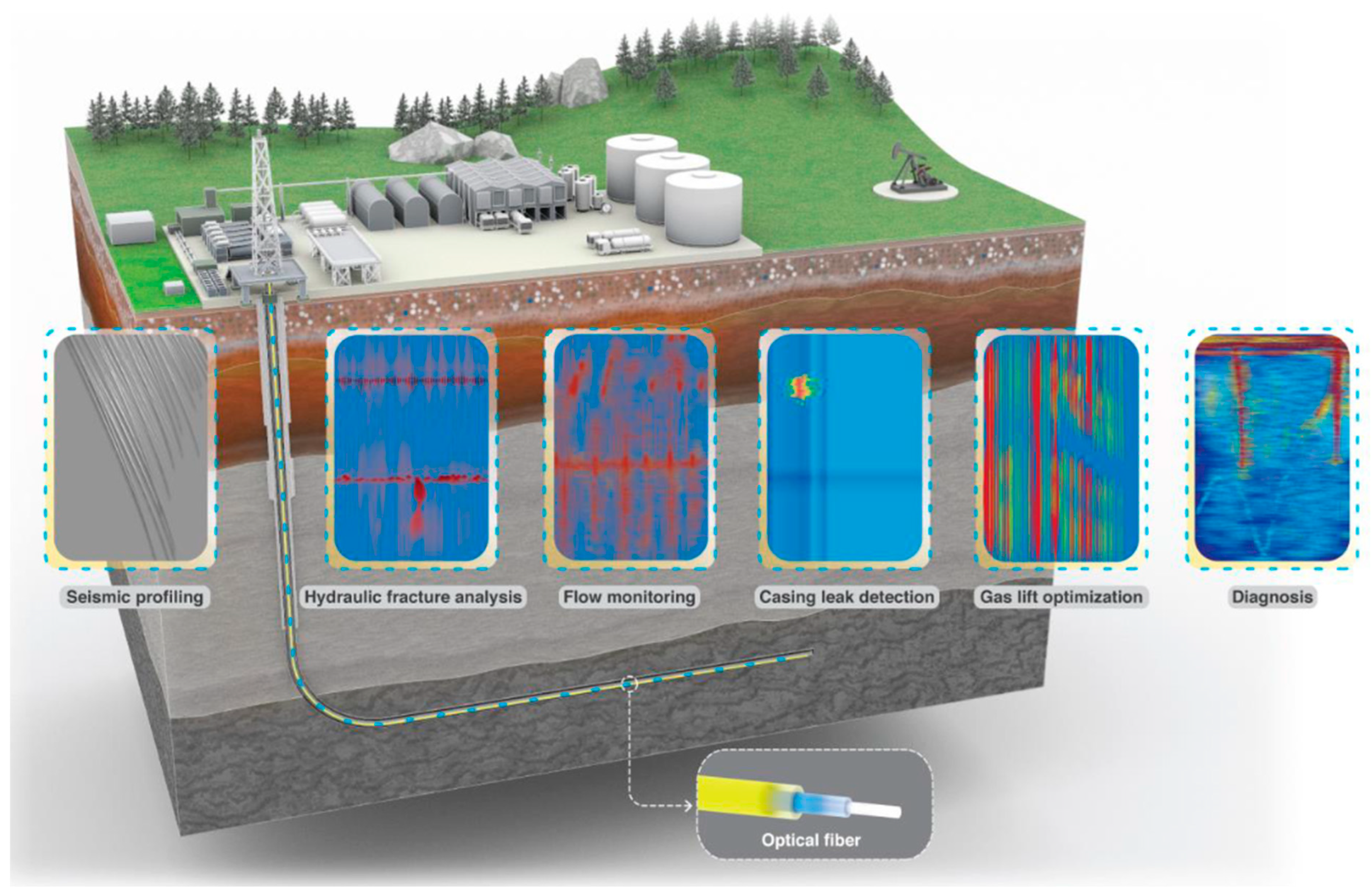
Ensuring well integrity fundamentally relies on a combination of robust initial design, meticulous execution during construction, prudent operational practices, and continuous monitoring and maintenance throughout the well’s life As shown in Figure 29, fiber optic sensing technology enables a range of real-time monitoring applications—including seismic profiling, hydraulic fracture analysis, flow monitoring, and casing leak detection—providing continuous data streams critical for well integrity management and operational optimization. Key recommendations drawn from industry standards, best practices, and research findings include the following:
Rigorous Well Design and Material Selection: The design phase must adhere to established guidelines and standards (e.g., ISO 16530-1, 2017; NORSOK D-010, 2021; API Specification 5CT, 2018 [276]; API RP 96, 2013). This involves selecting casing materials with appropriate grade, weight, and connection type based on a thorough analysis of anticipated lifetime loads (tension, compression, burst, collapse), temperature profiles, potential corrosive agents (CO2, H2S, chlorides), and specific risks like SSC or hydrogen embrittlement according to NACE MR0175/ISO 15156 standard. Using corrosion-resistant alloys (CRAs) may be necessary in highly aggressive environments [22]. Cement slurry design must be tailored to downhole conditions (temperature, pressure, formation type, fluid chemistry), targeting properties like appropriate density for pressure control, adequate compressive strength development, low fluid loss, minimal shrinkage, good bonding characteristics, and resistance to gas migration or chemical attack. Utilizing advanced cement systems (flexible, expansive, self-healing, CO2/H2 resistant) should be considered where conditions warrant [55]. Well trajectories should be optimized to minimize dogleg severity and associated stresses. The design must explicitly incorporate the two-barrier philosophy for all relevant operational phases [16,38].
Meticulous Construction and Cementing Practices: Achieving long-term integrity heavily depends on the quality of the initial construction, particularly the primary cementing job. This requires effective hole cleaning and mud conditioning prior to cementing, proper design and use of spacers and flushes to maximize mud displacement, adequate casing centralization using appropriate centralizers (especially in deviated/horizontal sections) to ensure uniform annular space, and controlled pumping rates and pressures during cement placement to avoid fracturing the formation or compromising slurry properties. Careful handling and proper make-up of casing connections are also critical to avoid initial damage.
Prudent Operational Management: During the production or injection phase, operational parameters should be managed to minimize integrity risks. This includes avoiding rapid changes in temperature or pressure, where possible, to reduce cyclic stress impacts (rate management to reduce shock). Operating within established pressure limits based on formation strength and barrier capacity is essential [59]. Implementing effective corrosion management programs (e.g., inhibition, monitoring) is crucial in corrosive environments.
Comprehensive Monitoring and Surveillance: Regular monitoring is key to detecting potential integrity issues early before they escalate. This involves routine annular pressure monitoring to detect SCP or anomalous pressure buildup [36]. Periodic logging using appropriate tools (CBL/VDL/Ultrasonic for cement bond, Caliper/EM for casing inspection, Temperature/Noise/Tracer for leak detection) should be scheduled based on risk assessment. Utilizing advanced monitoring technologies like fiber-optic sensing (DTS/DAS) or permanent downhole gauges can provide valuable real-time data. Functional testing of safety-critical elements (e.g., DHSVs, wellhead valves) must be performed regularly [38].
Systematic Integrity Management and Remediation: Implementing a formal Well Integrity Management System (WIMS) provides a structured framework for managing all aspects of well integrity, including risk assessment, monitoring, scheduling, data management, anomaly evaluation, and documentation [277,278]. When integrity issues are detected, appropriate remedial measures must be implemented promptly. Options include squeeze cementing to seal leaks, installation of casing patches to repair localized damage, chemical treatments (e.g., scale or corrosion inhibition), or major well workovers/recompletions to replace failed components. The selection of the remedial strategy should be based on a thorough diagnosis of the problem.
Adherence to Standards and Regulations: Compliance with relevant international, national, and corporate standards and regulations (e.g., ISO 16530, NORSOK D-010, API RPs, ANP Resolution 46, OEUK Guidelines) is fundamental for establishing and maintaining minimum safety and environmental protection levels [2,24,279,280].
Figure 29. An illustration of the multi-functional applications of fiber optic sensing in wellbore integrity and performance monitoring. Key applications include seismic profiling, hydraulic fracture analysis, flow monitoring, casing leak detection, gas lift optimization, and diagnostic analyses. The optical fiber (shown in yellow and blue) is permanently deployed along the wellbore, enabling real-time distributed sensing and providing a paradigm shift from conventional discrete measurements to continuous, integrated well integrity monitoring [281]. Reproduced with permission from [281].
Energies 18 04757 g029

15. Conclusions

This comprehensive review has underscored the multifaceted nature of well integrity challenges across conventional production, unconventional development, and subsurface storage applications. It highlighted how evolving operational demands, harsh downhole environments, and time-dependent degradation processes expose casing, cement, and sealing systems to a spectrum of mechanical, chemical, and thermal failure mechanisms. Despite advancements in materials, standards, and monitoring technologies, well integrity failures—especially sustained casing pressure, corrosion, and cement degradation—remain prevalent. The paper emphasizes the critical need for a proactive, lifecycle-based approach that integrates rigorous design, continuous surveillance, risk-informed management, and adaptive interventions. Additionally, the review identifies persistent knowledge gaps, particularly concerning long-term performance in CO2 and H2 storage wells, predictive modeling of barrier degradation, and the mitigation of legacy well risks. Addressing these gaps requires multidisciplinary collaboration, standardized testing protocols for new materials, and full integration of digital technologies such as AI and digital twins into well integrity management systems. As the global energy transition accelerates, ensuring well integrity will be essential not only for operational safety and environmental stewardship but also for enabling secure and scalable deployment of subsurface storage solutions. This will require a two-pronged approach: the urgent modernization of standards (e.g., API, ISO, NORSOK) to address new frontiers like hydrogen storage, and the deep integration of AI and digital twins to enable truly predictive well integrity monitoring.

16. Outlook

The trajectory of well integrity management is decisively moving towards systems that are more intelligent, integrated, predictive, and sustainable. The ambition of achieving fully autonomous well integrity systems represents a significant frontier, blending advancements in artificial intelligence (AI), robotics, and sensor technology. Future AI applications may extend beyond current predictive analytics to encompass automated interpretation of complex logging data (e.g., using computer vision for ultrasonic images), natural language processing to extract critical information from historical maintenance reports, and dynamic risk assessment models that continuously update based on real-time inputs. Robotics holds potential for automating routine inspections, such as drones equipped with gas detectors for surface facility surveillance or downhole robotic crawlers for internal casing inspection and minor repairs, reducing human exposure and enabling access to challenging environments. However, achieving true autonomy requires overcoming significant hurdles related to algorithm validation, ensuring fail-safe decision-making in complex scenarios, and establishing a robust communication and control infrastructure.
Simultaneously, the increasing focus on environmental stewardship and corporate responsibility is driving the integration of sustainability metrics and ESG (environmental, social, governance) reporting into the core of well integrity practices. Operators will face growing pressure from investors, regulators, and the public to demonstrate tangible performance in minimizing environmental impact. This translates into a need for quantifiable metrics related to well integrity, such as verified methane emission rates from well sites, leakage statistics, barrier failure frequencies, and robust verification of long-term plug and abandonment (P&A) effectiveness, particularly for wells used in geological storage. Effective well integrity management becomes a direct enabler of corporate climate goals and is increasingly tied to maintaining a social license to operate.
The convergence of digital technologies offers powerful tools for enhancing transparency and accountability, especially in the context of carbon management. The integration of digital twins with carbon accountability frameworks is poised to provide verifiable evidence of secure CO2 storage. By combining real-time sensor data (pressure, temperature, fluid composition) with validated simulation models, digital twins can offer dynamic assessments of containment and provide auditable data trails supporting monitoring, reporting, and verification (MRV) protocols required for carbon credits or regulatory compliance. Technologies like blockchain are also being explored for creating immutable records of integrity checks, interventions, and monitored performance, further bolstering confidence in long-term storage security.
Addressing the evolving challenges requires parallel advancements in policy, standardization, and global collaboration. There is a pressing need to develop or refine standards specifically addressing the unique material compatibility and operational risks associated with underground hydrogen storage, standardized methodologies for validating the long-term effectiveness of P&A barriers over multi-century timescales, protocols for the validation and certification of AI/ML models used in safety-critical integrity decisions, and frameworks for secure data sharing to facilitate industry-wide learning from integrity incidents and near-misses. International collaboration through bodies like ISO, API, SPE, and regional regulatory forums will be crucial for harmonizing best practices, particularly for managing cross-border resources or storage complexes.
Furthermore, the industry must continue to tackle persistent and emerging technical hurdles. Managing the vast portfolio of aging infrastructure globally demands innovative life extension strategies, reliable RUL prediction models, and cost-effective remediation techniques. Pushing operational boundaries into ultra-deepwater and HPHT environments necessitates continued development of materials (CRAs, advanced elastomers, high-performance cements) and sensors capable of withstanding extreme conditions. The intensification of drilling in unconventional plays with multi-well pads requires sophisticated geomechanical modeling to manage inter-well stress interference and mitigate casing deformation risks. For geological storage, the primary challenge remains demonstrating and ensuring containment over unprecedented timescales (hundreds to thousands of years), demanding breakthroughs in ultra-long-term predictive modeling, durable materials, and cost-effective, non-intrusive monitoring techniques capable of detecting subtle changes indicative of potential leakage.
Innovations in advanced materials will likely continue, potentially moving towards in situ repair solutions where smart materials deployed downhole can activate to seal breaches autonomously, or advanced coatings providing multi-functional protection (corrosion, wear, thermal insulation). Progress in sensor technology, including miniaturization, enhanced robustness, lower costs, and improved wireless downhole communication, could enable denser, permanent monitoring networks providing unprecedented spatial and temporal resolution of wellbore conditions. The concept of a circular economy may also influence future practices, promoting the repurposing of depleted wells for geothermal energy or storage, and encouraging the development of more sustainable P&A materials and techniques that minimize environmental footprint. The trend towards remote operations, accelerated by digitalization, will necessitate highly reliable remote integrity monitoring and verification systems, coupled with robust cybersecurity measures to protect increasingly connected WIMS and control systems from malicious interference, which itself represents a critical aspect of operational integrity.
Ultimately, the future of well integrity hinges on embracing a holistic, integrated approach. This means breaking down traditional silos between disciplines—integrating insights from geomechanics, materials science, reservoir engineering, data science, and operations management. It also means recognizing that technology alone is insufficient; fostering a strong safety culture, ensuring personnel competency through continuous training, and establishing clear organizational responsibilities remain fundamental pillars of effective well integrity management. By combining technological innovation with rigorous engineering principles and an unwavering commitment to safety and environmental protection, the industry can navigate the complexities of modern energy production and storage, ensuring the long-term integrity of well assets across their entire lifecycle.

Author Contributions

Conceptualization, A.A.S.A. and K.S.; investigation, A.A.S.A. and A.A.; data curation, A.A.; methodology, M.D.; supervision, K.S. and M.D.; project administration, K.S.; writing—review and editing, A.A.S.A., K.S., M.D. and A.A.; critical review, K.S. All authors have read and agreed to the published version of the manuscript.

Funding

This research received no external funding.

Data Availability Statement

No new data were created or analyzed in this study. Data sharing is not applicable to this article.

Conflicts of Interest

Author Ahmed Alsaedi was employed by the company SLB. The remaining authors declare that the research was conducted in the absence of any commercial or financial relationships that could be construed as a potential conflict of interest.

References

  1. Oziegbe Iriogbe, H.; Ebeh, C.O.; Onita, F.B. Well integrity management and optimization: A review of techniques and tools. Int. J. Sch. Res. Rev. 2024, 5, 79–87. [Google Scholar] [CrossRef]
  2. ISO/TS 16530-2; Well Integrity. Part 2: Well Integrity for the Operational Phase. ISO: Geneva, Switzerland, 2014. Available online: https://www.iso.org/standard/57056.html (accessed on 26 April 2025).
  3. Ibukun, M.; Elyan, E.; Amish, M.; Njuguna, J.; Oluyemi, G.F. A Review of Well Life Cycle Integrity Challenges in the Oil and Gas Industry and Its Implications for Sustained Casing Pressure (SCP). Energies 2024, 17, 5562. [Google Scholar] [CrossRef]
  4. Maury Fernandez, D.; Emadi, H.; Hussain, A.; Thiyagarajan, S.R. A holistic review on wellbore integrity challenges associated with underground hydrogen storage. Int. J. Hydrogen Energy 2024, 57, 240–262. [Google Scholar] [CrossRef]
  5. Dusseault, M.B.; Gray, M.N.; Nawrocki, P.A. Why Oilwells Leak: Cement Behavior and Long-Term Consequences. In Proceedings of the International Oil and Gas Conference and Exhibition in China, IOGCEC, Beijing, China, 7–10 November 2000; pp. 623–630. [Google Scholar] [CrossRef]
  6. Skogdalen, J.E.; Utne, I.B.; Vinnem, J.E. Developing safety indicators for preventing offshore oil and gas deepwater drilling blowouts. Saf. Sci. 2011, 49, 1187–1199. [Google Scholar] [CrossRef]
  7. King, G.E.; Valencia, R.L. Environmental Risk and Well Integrity of Plugged and Abandoned Wells. In Proceedings of the SPE Annual Technical Conference and Exhibition, Amsterdam, The Netherlands, 27–29 October 2014; Volume 6, pp. 4852–4868. [Google Scholar] [CrossRef]
  8. Yakoot, M.S.; Elgibaly, A.A.; Ragab, A.M.S.; Mahmoud, O. Well integrity management in mature fields: A state-of-the-art review on the system structure and maturity. J. Pet. Explor. Prod. 2021, 11, 1833–1853. [Google Scholar] [CrossRef]
  9. Fleckenstein, W.W.; Eustes, A.W.; Miller, M.G. Burst-Induced Stresses in Cemented Wellbores. SPE Drill. Complet. 2001, 16, 74–82. [Google Scholar] [CrossRef]
  10. Kiran, R.; Teodoriu, C.; Dadmohammadi, Y.; Nygaard, R.; Wood, D.; Mokhtari, M.; Salehi, S. Identification and evaluation of well integrity and causes of failure of well integrity barriers (A review). J. Nat. Gas. Sci. Eng. 2017, 45, 511–526. [Google Scholar] [CrossRef]
  11. Nygaard, R.; Salehi, S.; Weideman, B.; Lavoie, R. Effect of Dynamic Loading on Wellbore Leakage for the Wabamun Area CO2-Sequestration Project. J. Can. Pet. Technol. 2014, 53, 69–82. [Google Scholar] [CrossRef]
  12. Alberdi-Pagola, P.; Fischer, G. Review of Integrity Loss Detection and Quantification Due to Cracking in Cemented Wells. SPE J. 2023, 28, 965–982. [Google Scholar] [CrossRef]
  13. Vrålstad, T.; Skorpa, R.; Werner, B. Experimental Studies on Cement Sheath Integrity During Pressure Cycling. In Proceedings of the SPE/IADC Drilling Conference, The Hague, The Netherlands, 5–7 March 2019. [Google Scholar] [CrossRef]
  14. Wang, Y.; Gao, D.; Wang, J. New Model for Prediction of Sustained Casing Pressure of Deepwater Wells. In Proceedings of the 30th International Ocean and Polar Engineering Conference, Virtual, 11–16 October 2020. [Google Scholar]
  15. Davies, R.J.; Almond, S.; Ward, R.S.; Jackson, R.B.; Adams, C.; Worrall, F.; Herringshaw, L.G.; Gluyas, J.G.; Whitehead, M.A. Oil and gas wells and their integrity: Implications for shale and unconventional resource exploitation. Mar. Pet. Geol. 2014, 56, 239–254. [Google Scholar] [CrossRef]
  16. NORSOK D-010; Well Integrity in Drilling and Well Operations. Standards Norway: Oslo, Norway, 2021. Available online: https://online.standard.no/en/norsok-d-010-2021 (accessed on 26 April 2025).
  17. Solovyeva, V.A.; Almuhammadi, K.H.; Badeghaish, W.O. Current Downhole Corrosion Control Solutions and Trends in the Oil and Gas Industry: A Review. Materials 2023, 16, 1795. [Google Scholar] [CrossRef]
  18. Arjomand, E.; Bennett, T.; Nguyen, G.D. Evaluation of cement sheath integrity subject to enhanced pressure. J. Pet. Sci. Eng. 2018, 170, 1–13. [Google Scholar] [CrossRef]
  19. Jackson, R.B.; Vengosh, A.; Darrah, T.H.; Warner, N.R.; Down, A.; Poreda, R.J.; Osborn, S.G.; Zhao, K.; Karr, J.D. Increased stray gas abundance in a subset of drinking water wells near Marcellus shale gas extraction. Proc. Natl. Acad. Sci. USA 2013, 110, 11250–11255. [Google Scholar] [CrossRef]
  20. Semwogerere, D.; Sangesland, S.; Vatn, J.; Pavlov, A.; Colombo, D. Well integrity and late life extension—A current industry state of practice and literature review. Geoenergy Sci. Eng. 2025, 244, 213419. [Google Scholar] [CrossRef]
  21. API STD 65-2; Isolating Potential Flow Zones During Well Construction. API Publishing Services: Washington, DC, USA, 2010.
  22. Askari, M.; Aliofkhazraei, M.; Jafari, R.; Hamghalam, P.; Hajizadeh, A. Downhole corrosion inhibitors for oil and gas production—A review. Appl. Surf. Sci. Adv. 2021, 6, 100128. [Google Scholar] [CrossRef]
  23. Patel, H.; Salehi, S.; Ahmed, R.; Teodoriu, C. Review of elastomer seal assemblies in oil & gas wells: Performance evaluation, failure mechanisms, and gaps in industry standards. J. Pet. Sci. Eng. 2019, 179, 1046–1062. [Google Scholar] [CrossRef]
  24. Jaculli, M.A.; Mendes, R.P.; Miura, K. Methodology for Assessing Wellhead Integrity During Its Life Cycle. In Proceedings of the ASME 2020 39th International Conference on Ocean, Offshore and Arctic Engineering, Virtual, 3–7 August 2020. [Google Scholar]
  25. Salem, A.M.; Yakoot, M.S.; Mahmoud, O. A novel machine learning model for autonomous analysis and diagnosis of well integrity failures in artificial-lift production systems. Adv. Geo-Energy Res. 2022, 6, 123–142. [Google Scholar] [CrossRef]
  26. Sun, B.; Zhang, M.; Sun, Q.; Zhong, J.; Shao, G. Review on natural hydrogen wells safety. Nat. Commun. 2025, 16, 369. [Google Scholar] [CrossRef]
  27. Patel, H.; Salehi, S. Development of an Advanced Finite Element Model and Parametric Study to Evaluate Cement Sheath Barrier. J. Energy Resour. Technol. Trans. ASME 2019, 141, 1–21. [Google Scholar] [CrossRef]
  28. Yakoot, M.S.; Ragab, A.M.S.; Mahmoud, O. Machine Learning Application for Gas Lift Performance and Well Integrity. In Proceedings of the Society of Petroleum Engineers—SPE Europec Featured at 82nd EAGE Conference and Exhibition, EURO, Amsterdam, The Netherlands, 18–21 October 2021. [Google Scholar] [CrossRef]
  29. Law, R. The Ekofisk Bravo Blowout, 1977. In Oil Spill Science and Technology; Gulf Professional Publishing: Largo, FL, USA, 2011; pp. 1107–1108. [Google Scholar] [CrossRef]
  30. Olberg, T.; Gilhuus, T.; Leraand, F.; Haga, J. Re-Entry and Relief Well Drilling To Kill an Underground Blowout in a Subsea Well: A Case History of Well 2/4-14. In Proceedings of the SPE/IADC Drilling Conference, Amsterdam, The Netherlands, 11–14 March 1991; pp. 775–783. [Google Scholar] [CrossRef]
  31. Pettersen, G.; Ytredal, E.B. The Snorre A Incident 28 November 2004: Lessons Learned. In Proceedings of the SPE International Health, Safety & Environment Conference, Abu Dhabi, United Arab Emirates, 2–4 April 2006. SPE Reprint Series. [Google Scholar] [CrossRef]
  32. Hayes, J. Operator competence and capacity—Lessons from the Montara blowout. Saf. Sci. 2012, 50, 563–574. [Google Scholar] [CrossRef]
  33. Stacey, A.; Ersdal, G. Structural Integrity Management of Ageing Offshore Structures: A Regulatory Perspective. In Ageing and Life Extension of Offshore Facilities; ASME: New York, NY, USA, 2022; pp. 5–20. [Google Scholar] [CrossRef]
  34. Johansen, I.L.; Rausand, M. Barrier management in the offshore oil and gas industry. J. Loss Prev. Process Ind. 2015, 34, 49–55. [Google Scholar] [CrossRef]
  35. Tangstad, J.R. Assessment of Dynamic Barriers in Oil/Gas Well Operations: Vurdering av Dynamiske Barrierer i Olje/Gass Brønner. Master’s Thesis, Norwegian University of Science and Technology, Trondheim, Norway, 2014; p. 104. [Google Scholar]
  36. API RP90. Available online: https://www.api.org/products-and-services/standards/important-standards-announcements/90-1 (accessed on 26 April 2025).
  37. API RP 96; Deepwater Well Design and Construction. API: Washington, DC, USA, 2013. Available online: https://www.apiwebstore.org/standards/96?utm_term=api%20rp%2096&utm_campaign=US+Brand&utm_source=bing&utm_medium=ppc&hsa_acc=4890137417&hsa_cam=11564532636&hsa_grp=1355700341218503&hsa_ad=&hsa_src=o&hsa_tgt=kwd-84732449229502:loc-4126&hsa_kw=api%20rp%2096&hsa_mt=e&hsa_net=adwords&hsa_ver=3&msclkid=b62f7a421336112d1bde124cfdb36c01 (accessed on 26 April 2025).
  38. ISO 16530-1; Petroleum and Natural Gas Industries—Well Integrity—Part 1: Life Cycle Governance. ISO: Geneva, Switzerland, 2017. Available online: https://www.iso.org/standard/63192.html (accessed on 26 April 2025).
  39. Anunciação Jaculli, M.; Choueri, N.; da Mata, C.R.; Aparecida Silva Leite, A.G.; Pelaquim Mendes, J.R.; Colombo, D. Well safety and integrity evaluation of offshore wells: A review of past, present, and future. J. Pet. Sci. Eng. 2022, 212, 110329. [Google Scholar] [CrossRef]
  40. Well Life Cycle Integrity Guidelines—Issue 4. Available online: https://oeuk.org.uk/product/well-life-cycle-integrity-guidelines-issue-4/ (accessed on 19 April 2025).
  41. Zhang, Q.; Lian, Z.; Lin, T. Prediction of residual burst strength of worn casing by theoretical and numerical modelling. Int. J. Press. Vessel. Pip. 2020, 188, 104195. [Google Scholar] [CrossRef]
  42. The Lakeview Gusher. Available online: http://www.sjvgeology.org/history/lakeview.html (accessed on 19 April 2025).
  43. Oil & Gas: Fire in the Desert|TIME. Available online: https://time.com/archive/6623264/oil-gas-fire-in-the-desert/ (accessed on 19 April 2025).
  44. Soto, L.A.; Botello, A.V.; Licea-Durán, S.; Lizárraga-Partida, M.L.; Yáñez-Arancibia, A. The environmental legacy of the Ixtoc-I oil spill in Campeche Sound, southwestern Gulf of Mexico. Front. Mar. Sci. 2014, 1, 116502. [Google Scholar] [CrossRef]
  45. Whyte, D.; Tucker, E. Regulating Safety, Regulating Profit: Cost-Cutting, Injury and Death in the British North Sea After Piper Alpha; Routledge: Abingdon, UK, 2016; pp. 186–210. [Google Scholar]
  46. Tingay, M.R.P.; Rudolph, M.L.; Manga, M.; Davies, R.J.; Wang, C.-Y. Initiation of the Lusi mudflow disaster. Nat. Geosci. 2015, 8, 493–494. [Google Scholar] [CrossRef]
  47. Response to the Montara Wellhead Platform Incident|Australian Maritime Safety Authority. Available online: https://www.amsa.gov.au/marine-environment/incidents-and-exercises/response-montara-wellhead-platform-incident (accessed on 19 April 2025).
  48. Gibson, M. HPHT Field Development Experience Transfer. In Proceedings of the Society of Petroleum Engineers-IADC/SPE Asia Pacific Drilling Technology Conference, Singapore, 22–24 August 2016. [Google Scholar] [CrossRef]
  49. CSB Issues Final Report on Fatal Gas Well Blowout—ProQuest. Available online: https://www.proquest.com/openview/78d16680837e9cc9810d62a81bdb570c/1?cbl=47267&pq-origsite=gscholar (accessed on 19 April 2025).
  50. Gao, B.; Wang, L.; Hu, T. Testing String Dynamics When Jarring Stuck Packer. In Proceedings of the 29th International Ocean and Polar Engineering Conference, Honolulu, HI, USA, 16–21 June 2019. [Google Scholar]
  51. Vrålstad, T.; Saasen, A.; Fjær, E.; Øia, T.; Ytrehus, J.D.; Khalifeh, M. Plug & abandonment of offshore wells: Ensuring long-term well integrity and cost-efficiency. J. Pet. Sci. Eng. 2019, 173, 478–491. [Google Scholar] [CrossRef]
  52. Mohammed, A.I. An Investigation of Casing Structural Integrity in Shale Gas Horizontal Wells During Hydraulic Fracturing Using FEA and Machine Learning Algorithms. Ph.D. Thesis, Robert Gordon University, Aberdeen, UK, 2021. [Google Scholar]
  53. Alsubaih, A.A.; Nygaard, R. Shale Instability of Deviated Wellbores in Southern Iraqi Fields. Master’s Thesis, Missouri University of Science and Technology, Rolla, MO, USA, 2016. [Google Scholar]
  54. Godwin, W.H.; Cole, W.F. Drilling Hazards; Springer: Cham, Switzerland, 2018; pp. 244–248. [Google Scholar] [CrossRef]
  55. Nelson, E.B.; Guillot, D. Well Cementing, 2nd ed.; Schlumberger: Athens, TX, USA, 2006. [Google Scholar]
  56. Ma, L.; Zhang, K.; Xie, J.; Yuan, L.; Geng, H.; Ning, K.; Ma, L.; Zhang, K.; Xie, J.; Yuan, L.; et al. Research Progress and Prospect of Well Integrity Technology. J. Power Energy Eng. 2020, 8, 45–54. [Google Scholar] [CrossRef]
  57. Wu, J.; Knauss, M.E.; Kritzler, T. Casing Failures in Cyclic Steam Injection Wells. In Proceedings of the Society of Petroleum Engineers—IADC/SPE Asia Pacific Drilling Technology Conference 2008—“Drilling Technology to Access Future Energy Demand and Environmental Challenges”, Jakarta, Indonesia, 25–27 August 2008; pp. 26–32. [Google Scholar] [CrossRef]
  58. Strazisar, B.; Kutchko, B.; Huerta, N. Chemical Reactions of Wellbore Cement Under CO2 Storage Conditions: Effects of Cement Additives. Energy Procedia 2009, 1, 3603–3607. [Google Scholar] [CrossRef]
  59. Eme, C.; Dosunmu, A.; Nweke, F.; Udom, G.; Anyanwu, C.; Charles, E. Caprock Integrity Analysis during Hydraulic Fracturing For Produced Water Disposal: A Case Study in Niger-Delta. IOSR J. Appl. Geol. Geophys. 2019, 7, 17–24. [Google Scholar] [CrossRef]
  60. Zhang, K.; Liu, X.F.; Wang, D.B.; Zheng, B.; Chen, T.H.; Wang, Q.; Bai, H.; Yao, E.D.; Zhou, F.J. A review of reservoir damage during hydraulic fracturing of deep and ultra-deep reservoirs. Pet. Sci. 2024, 21, 384–409. [Google Scholar] [CrossRef]
  61. Settari, A. Reservoir Compaction. J. Pet. Technol. 2002, 54, 62–69. [Google Scholar] [CrossRef]
  62. Khalifeh, M.; Saasen, A. Introduction to Permanent Plug and Abandonment of Wells; Springer Nature: Dordrecht, The Netherlands, 2020; Volume 12. [Google Scholar] [CrossRef]
  63. Alberta Energy Regulator General Well Data|Alberta Energy Regulator. Available online: https://www.aer.ca/data-and-performance-reports/activity-and-data/lists-and-activities/general-well-data (accessed on 26 July 2025).
  64. Wang, Y.; Liu, K.; Gao, D. Investigation of the interface cracks on the cement sheath stress in shale gas wells during hydraulic fracturing. J. Pet. Sci. Eng. 2021, 205, 108981. [Google Scholar] [CrossRef]
  65. Zhu, H.; Lin, Y.; Zeng, D.; Zhang, D.; Chen, H.; Wang, W. Mechanism and prediction analysis of sustained casing pressure in “A” annulus of CO2 injection well. J. Pet. Sci. Eng. 2012, 92–93, 1–10. [Google Scholar] [CrossRef]
  66. Wu, S.; Zhang, L.; Fan, J.; Zhang, X.; Liu, D.; Wang, D. A leakage diagnosis testing model for gas wells with sustained casing pressure from offshore platform. J. Nat. Gas. Sci. Eng. 2018, 55, 276–287. [Google Scholar] [CrossRef]
  67. Xu, R.; Wojtanowicz, A.K. Pressure buildup test analysis in wells with sustained casing pressure. J. Nat. Gas. Sci. Eng. 2017, 38, 608–620. [Google Scholar] [CrossRef]
  68. Wojtanowicz, A.K.; Nishikawa, S.; Rong, X. Diagnosis and Remediation of Sustained Casing Pressure in Wells; Final Report; Louisiana State University: Baton Rouge, LA, USA, 2021. [Google Scholar]
  69. Bourgoyne, A.T.; Stuart Scott, L.L.; Wojciech Manowski, L. A Review of Sustained Casing Pressure Occurring on the Ocs. Available online: https://www.bsee.gov/sites/bsee.gov/files/tap-technical-assessment-program/008de.pdf (accessed on 29 April 2025).
  70. Jónsson, M.Þ.; Pálsson, H.; Karlsdóttir, S.N. Structural Analysis of the Casings in High-Temperature Geothermal Wells. In Proceedings of the Deep Roots of Geothermal Systems (DRG) Final Meeting, Reykjavik, Iceland, 14 December 2017. [Google Scholar]
  71. Akpan, E.G. Wellhead Fatigue Response Affected by Seabed Interaction. Master’s Thesis, Memorial University of Newfoundland, St. John’s, NL, Canada, 2018. [Google Scholar]
  72. Sotoodeh, K. A Review of Valve Stem Sealing to Prevent Leakage from the Valve and Its Effect on Valve Operation. J. Fail. Anal. Prev. 2021, 21, 9–16. [Google Scholar] [CrossRef]
  73. Davies, D.; Al-Khelaiwi, F.; Muradov, K.; Qing, Y.; Rafiei, Y.; Aggrey, G.; Al-Mutairi, F. Applications of permanent sensors for real-time well management. Leading Edge 2008, 27, 1654–1661. [Google Scholar] [CrossRef]
  74. Farhadiroushan, M.; Parker, T.R.; Shatalin, S.; Chen, Z.; Gillies, A.; Aghayev, R.; Pérez, D.; Maxwell, J.; Milne, C. Integrated Distributed Strain Sensing for Wellbore and Reservoir Monitoring. In Distributed Acoustic Sensing in Borehole Geophysics; Wiley: Hoboken, NJ, USA, 2024; pp. 17–28. [Google Scholar] [CrossRef]
  75. Kaldal, G.S.; Jonsson, M.T.; Palsson, H.; Karlsdottir, S.N. Structural modeling of the casings in high temperature geothermal wells. Geothermics 2015, 55, 126–137. [Google Scholar] [CrossRef]
  76. Evans, G.W.; Harriman, D.W. Laboratory Tests on Collapse Resistance of Cemented Casing. In Proceedings of the Fall Meeting of the Society of Petroleum Engineers of AIME, San Antonio, TX, USA, 8–11 October 1972. [Google Scholar] [CrossRef]
  77. Yudovich, A.; Chin, L.Y.; Morgan, D.R. Casing Deformation In Ekofisk. In Proceedings of the Annual Offshore Technology Conference, Houston, TX, USA, 2–5 May 1988; pp. 63–72. [Google Scholar] [CrossRef]
  78. El-Sayed, A.A.H.; Khalaf, F. Resistance of Cemented Concentric Casing Strings Under Nonuniform Loading. SPE Drill. Eng. 1992, 7, 59–64. [Google Scholar] [CrossRef]
  79. Rodriguez, W.J.; Fleckenstein, W.W.; Eustes, A.W. Simulation of Collapse Loads on Cemented Casing Using Finite Element Analysis. In Proceedings of the SPE Annual Technical Conference and Exhibition, Denver, CO, USA, 5–8 October 2003. [Google Scholar] [CrossRef]
  80. Fleckenstein, W.W.; Eustes, A.W.; Rodriguez, W.J.; Berger, A.; Sanchez, F.J. AADE-05-NTCE-14 Cemented Casing: The True Stress Picture. Available online: https://www.aade.org/application/files/9215/7304/0396/AADE-05-NTCE-14_Fleckenstein.pdf (accessed on 16 May 2025).
  81. Fernandes, A.A.; Vanni, G.S.; Martinello, I.A.; de Souza Terra, F.; Sales, I.M.; Guedes, J.; da Silva Vasconcelos, K. Evolving well control procedures with MPD on floaters. In Proceedings of the Society of Petroleum Engineers—IADC/SPE Managed Pressure Drilling and Underbalanced Operations Conference and Exhibition, MPDU, Amsterdam, The Netherlands, 9–10 April 2019. [Google Scholar] [CrossRef]
  82. Tabatabaei, M.; Taleghani, A.D.; Ahmadi, M. Partial Annular Cracks around Cemented Casing Interfaces. In Proceedings of the 50th U.S. Rock Mechanics/Geomechanics Symposium, Houston, TX, USA, 26–29 June 2016. [Google Scholar]
  83. Berger, A.; Fleckenstein, W.W.; Eustes, A.W.; Thonhauser, G. Effect of Eccentricity, Voids, Cement Channels, and Pore Pressure Decline on Collapse Resistance of Casing. In Proceedings of the SPE Annual Technical Conference and Exhibition, Houston, TX, USA, 26–29 September 2004. [Google Scholar] [CrossRef]
  84. Ahmed, S.; Salehi, S. Failure mechanisms of the wellbore mechanical barrier systems: Implications for well integrity. J. Energy Resour. Technol. Trans. ASME 2021, 143, 073007. [Google Scholar] [CrossRef]
  85. Yuan, Z.; Schubert, J.; Teodoriu, C.; Gardoni, P. HPHT Gas Well Cementing Complications and its Effect on Casing Collapse Resistance. In Proceedings of the Society of Petroleum Engineers—SPE Oil and Gas India Conference and Exhibition, Mumbai, India, 28–30 March 2012; pp. 537–556. [Google Scholar] [CrossRef]
  86. Sun, R.; Yin, X.; Wang, B.; Zhang, G. Simultaneous inversion of petrophysical parameters based on Metropolis sampling algorithm. In Proceedings of the Society of Exploration Geophysicists International Exposition and 84th Annual Meeting SEG, Denver, CO, USA, 26–31 October 2014; pp. 2611–2615. [Google Scholar] [CrossRef]
  87. Huang, W.; Gao, D. A theoretical study of the critical external pressure for casing collapse. J. Nat. Gas. Sci. Eng. 2015, 27, 290–297. [Google Scholar] [CrossRef]
  88. Abdideh, M.; Hedayati Khah, S. Analytical and Numerical Study of Casing Collapse in Iranian Oil Field. Geotech. Geol. Eng. 2018, 36, 1723–1734. [Google Scholar] [CrossRef]
  89. Bastola, A.; Wang, J.; Mirzaee-Sisan, A.; Njuguna, J. Predicting Hydrostatic Collapse of Pipes Using Finite Element Analysis. In Proceedings of the International Conference on Offshore Mechanics and Arctic Engineering—OMAE, San Francisco, CA, USA, 8–13 June 2014; p. V06AT04A048. [Google Scholar] [CrossRef]
  90. Fang, J.; Wang, Y.; Gao, D. On the collapse resistance of multilayer cemented casing in directional well under anisotropic formation. J. Nat. Gas. Sci. Eng. 2015, 26, 409–418. [Google Scholar] [CrossRef]
  91. Li, C.; Samuel, R. Casing Integrity: Modeling Strength Degradation. In Proceedings of the SPE/IADC Drilling Conference, Fort Worth, TX, USA, 1–3 March 2016. [Google Scholar] [CrossRef]
  92. Nawathe, S.; Panico, M.; Baker, D.; Huang, W. Effect of Residual Stresses on Causing Sour Burst Pressure. In Proceedings of the Corrosion 2016, Vancouver, BC, Canada, 6–10 March 2016. [Google Scholar]
  93. Dall’Acqua, D.; Hodder, M.; Kaiser, T.M.V. Burst and Collapse Responses of Production Casing in Thermal Applications. SPE Drill. Complet. 2013, 28, 93–104. [Google Scholar] [CrossRef]
  94. Kalil, I.A.; McSpadden, A.R. Casing Burst Stresses in Particulate-Filled Annuli: Where Is the Cement? SPE Drill. Complet. 2012, 27, 473–485. [Google Scholar] [CrossRef]
  95. Kuanhai, D.; Xie, P.; Yue, Y.; Dezhi, Z.; Qiong, L.; Yuanhua, L. Study on the effect of interface failure between casing and cement sheath on casing stress under non-uniform in-situ stress. Appl. Math. Model. 2021, 91, 632–652. [Google Scholar] [CrossRef]
  96. Lubinski, A.; Althouse, A.W.S. Helical Buckling of Tubing Sealed in Packers. J. Pet. Technol. 1962, 14, 655–670. [Google Scholar] [CrossRef]
  97. Wang, Y.; Gao, D.; Fang, J. Mechanical characteristics analysis of casing-cement ring-formation multilayer composite system. Yingyong Lixue Xuebao/Chin. J. Appl. Mech. 2014, 31, 387–392. [Google Scholar] [CrossRef]
  98. Njuguna, J. Flutter prediction, suppression and control in aircraft composite wings as a design prerequisite: A survey. Struct. Control Health Monit. 2007, 14, 715–758. [Google Scholar] [CrossRef]
  99. Wu, J.; Knauss, M.E. Casing Temperature and Stress Analysis in Steam-Injection Wells. In Proceedings of the International Oil and Gas Conference and Exhibition in China 2006—Sustainable Growth for Oil and Gas 2006, Beijing, China, 5–7 December 2006; Volume 1, pp. 509–517. [Google Scholar] [CrossRef]
  100. Mitchell, S.; Moore, N.B.; Franks, J.; Liu, G.; Xiang, Y. Comparing the Results of a Full-Scale Buckling-Test Program to Actual Well Data: New Semiempirical Buckling Model and Methods of Reducing Buckling Effects. SPE Drill. Complet. 2011, 26, 578–596. [Google Scholar] [CrossRef]
  101. Menand, S.; Bjorset, A.; Macresy, L. A New Buckling Model Successfully Validated with Full-Scale Buckling Tests. In Proceedings of the 2011 AADE National Technical Conference & Exhibition, Houston, TX, USA, 12–14 April 2011; 3p. [Google Scholar] [CrossRef]
  102. Yan, W.; Zou, L.; Li, H.; Deng, J.; Ge, H.; Wang, H. Investigation of casing deformation during hydraulic fracturing in high geo-stress shale gas play. J. Pet. Sci. Eng. 2017, 150, 22–29. [Google Scholar] [CrossRef]
  103. Lian, Z.; Yu, H.; Lin, T.; Guo, J. A study on casing deformation failure during multi-stage hydraulic fracturing for the stimulated reservoir volume of horizontal shale wells. J. Nat. Gas. Sci. Eng. 2015, 23, 538–546. [Google Scholar] [CrossRef]
  104. Liu, W.; Yu, B.; Deng, J. Analytical method for evaluating stress field in casing-cement-formation system of oil/gas wells. Appl. Math. Mech. (Engl. Ed.) 2017, 38, 1273–1294. [Google Scholar] [CrossRef]
  105. Dusseault, M.B.; Bruno, M.S.; Barrera, J. Casing Shear: Causes, Cases, Cures. In Proceedings of the International Oil & Gas. Conference and Exhibition in China, IOGCEC, Beijing, China, 2–6 November 1998; Volume 1, pp. 337–345. [Google Scholar] [CrossRef]
  106. Gao, L.; Hsu, C.T.T. Fatigue of Concrete under Uniaxial Compression Cyclic Loading. Mater. J. 1998, 95, 575–581. [Google Scholar] [CrossRef]
  107. Lim, T.K.; Koska, R.; Tellier, E. Overcoming Installation Challenges to Wellhead and Conductor Fatigue. In Proceedings of the International Conference on Offshore Mechanics and Arctic Engineering—OMAE, Nantes, France, 9–14 June 2013; Volume 4B. [Google Scholar] [CrossRef]
  108. Payne, M.L. Fatigue Failure of API a-Round Casings in Drilling Service. In Proceedings of the SPE Annual Technical Conference and Exhibition, Houston, TX, USA, 3–6 October 1993. [Google Scholar]
  109. Liu, Z.; Samuel, R.; Gonzales, A.; Kang, Y. Analysis of Casing Fatigue Failure During Multistage Fracturing Operations. In Proceedings of the Society of Petroleum Engineers—Abu Dhabi International Petroleum Exhibition and Conference, ADIPEC, Abu Dhabi, United Arab Emirates, 11–15 November 2018. [Google Scholar] [CrossRef]
  110. Teodoriu, C.; Falcone, G. Comparing completion design in hydrocarbon and geothermal wells: The need to evaluate the integrity of casing connections subject to thermal stresses. Geothermics 2009, 38, 238–246. [Google Scholar] [CrossRef]
  111. Asbill, W.T.; Pattillo, P.D.; Rogers, W.M. Investigation of API 8 Round Casing Connection Performance—Part I: Introduction and Method of Analysis. J. Energy Resour. Technol. 1984, 106, 130–136. [Google Scholar] [CrossRef]
  112. Zhu, X.; Peng, P.; Jing, J.; Song, W. Research on casing erosion in reservoir section of gas storage wells based on Gas-solid Two-phase flow. Eng. Fail. Anal. 2022, 142, 106688. [Google Scholar] [CrossRef]
  113. Ji, N.; Wang, Z.; Jiang, W.; Wang, P.; Long, Y.; Wang, Z. Erosive wear behavior of casing steel during hydraulic fracturing operation in shale gas well. In Proceedings of the Fifth International Conference on Mechanical Engineering and Materials (ICMEM 2024), Nanchang, China, 5 March 2025; Volume 13547, pp. 444–450. [Google Scholar] [CrossRef]
  114. Ogunsesan, O.A.; Hossain, M.; Iyi, D.; Dhroubi, M.G. CFD modelling of pipe erosion due to sand transport. In Numerical Modelling in Engineering; Lecture Notes in Mechanical Engineering; Springer: Singapore, 2019; pp. 274–289. [Google Scholar] [CrossRef]
  115. Clark, H.M.I. A comparison of the erosion rate of casing steels by sand-oil suspensions. Wear 1991, 150, 217–230. [Google Scholar] [CrossRef]
  116. Lin, T.; Zhang, Q.; Lian, Z.; Chang, X.; Zhu, K.; Liu, Y. Evaluation of casing integrity defects considering wear and corrosion—Application to casing design. J. Nat. Gas. Sci. Eng. 2016, 29, 440–452. [Google Scholar] [CrossRef]
  117. Mao, L.; Cai, M.; Wang, G. Effect of rotation speed on the abrasive–erosive–corrosive wear of steel pipes against steel casings used in drilling for petroleum. Wear 2018, 410–411, 1–10. [Google Scholar] [CrossRef]
  118. Mohammed, A.I.; Oyeneyin, B.; Atchison, B.; Njuguna, J. Casing structural integrity and failure modes in a range of well types—A review. J. Nat. Gas. Sci. Eng. 2019, 68, 102898. [Google Scholar] [CrossRef]
  119. Noshi, C.I.; Noynaert, S.F.; Schubert, J.J. Casing Failure Data Analytics: A Novel Data Mining Approach in Predicting Casing Failures for Improved Drilling Performance and Production Optimization. In Proceedings of the SPE Annual Technical Conference and Exhibition, Dallas, TX, USA, 24–26 September 2018. [Google Scholar] [CrossRef]
  120. Porcaro, R.R.; Cândido, L.C.; Trindade, V.B.; De Faria, G.L.; Godefroid, L.B. Evaluation of standard API casing connections and parametric API Buttress improvement by finite element analysis. Mater. Res. 2017, 20, 130–137. [Google Scholar] [CrossRef]
  121. WestCan Oilfield Supply Home—WestCan Oilfield Supply. Available online: https://www.westcanoilfield.com/ (accessed on 24 June 2025).
  122. Jacobs, T. An Unconventional Challenge Can Casing Failures During Hydraulic Fracturing Be Stopped? J. Pet. Technol. 2020, 72, 26–32. [Google Scholar] [CrossRef]
  123. GATE Energy Common Failures in Oil and Gas Wells—GATE Energy. Available online: https://www.gate.energy/the-brainery/gat2004-gkp-2018-09/common-failures-in-oil-and-gas-wells (accessed on 26 July 2025).
  124. Xie, J.; Tao, G. Analysis of Casing Connections Subjected to Thermal Cycle Loading. In Proceedings of the 2010 SIMULIA Customer Conference, Providence, RI, USA, 25–27 May 2010; Dassault Systèmes: Providence, RI, USA, 2010; pp. 1–16. [Google Scholar]
  125. ISO/PAS 12835; Qualification of Casing Connections for Thermal Wells (First Edition). International Organization for Standardization: Geneva, Switzerland, 2013.
  126. King, G.E.; King, D.E. Environmental Risk Arising From Well-Construction Failure—Differences Between Barrier and Well Failure, and Estimates of Failure Frequency Across Common Well Types, Locations, and Well Age. SPE Prod. Oper. 2013, 28, 323–344. [Google Scholar] [CrossRef]
  127. Yang, B.; Xu, H.; Xiang, S.; Zhang, Z.; Su, K.; Yang, Y. Effects of Make-Up Torque on the Sealability of Sphere-Type Premium Connection for Tubing and Casing Strings. Processes 2023, 11, 256. [Google Scholar] [CrossRef]
  128. Quigley, M.S.; Lewis, D.B.; Boswell, R.S. Field Measurements of Casing Tension Forces. In Proceedings of the SPE Annual Technical Conference and Exhibition, New Orleans, LA, USA, 25–28 September 1994; pp. 357–364. [Google Scholar] [CrossRef]
  129. Yamada, K.; Furui, K. Efficient Integration Method of Large-Scale Reservoir Compaction and Small-Scale Casing Stability Models for Oilfield Casing Failure Analysis. In Proceedings of the Society of Petroleum Engineers—SPE Asia Pacific Oil and Gas Conference and Exhibition, APOGCE, Brisbane, Australia, 23–25 October 2018. [Google Scholar] [CrossRef]
  130. Cirimello, P.G.; Otegui, J.L.; Carfi, G.; Morris, W. Failure and integrity analysis of casings used for oil well drilling. Eng. Fail. Anal. 2017, 75, 1–14. [Google Scholar] [CrossRef]
  131. API RP 5C5; Recommended Practice on Procedures for Testing Casing and Tubing Connections (3rd ed.). American Petroleum Institute: Washington, DC, USA, 2017.
  132. ISO 13679; Petroleum and Natural Gas Industries—Procedures for Testing Casing and Tubing Connections (Second Edition). International Organization for Standardization: Geneva, Switzerland, 2019.
  133. Alsubaih, A.; Sepehrnoori, K.; Delshad, M. Development and Optimization of Self-Healing Cement for CO2 Injection and Storage Wells: Enhancing Long-Term Wellbore Integrity in Extreme Subsurface Conditions. Appl. Sci. 2025, 15, 5428. [Google Scholar] [CrossRef]
  134. Omosebi, O.; Maheshwari, H.; Ahmed, R.; Shah, S.; Osisanya, S.; Hassani, S.; DeBruijn, G.; Cornell, W.; Simon, D. Degradation of well cement in HPHT acidic environment: Effects of CO2 concentration and pressure. Cem. Concr. Compos. 2016, 74, 54–70. [Google Scholar] [CrossRef]
  135. Kutchko, B.G.; Strazisar, B.R.; Dzombak, D.A.; Lowry, G.V.; Thauiow, N. Degradation of well cement by CO2 under geologic sequestration conditions. Environ. Sci. Technol. 2007, 41, 4787–4792. [Google Scholar] [CrossRef]
  136. Omosebi, O.A.; Ahmed, R.M.; Shah, S.N. Mechanisms of Cement Degradation in HPHT Carbonic Acid Environment. In Proceedings of the SPE International Symposium on Oilfield Chemistry, Montgomery, TX, USA, 3–5 April 2017; pp. 448–468. [Google Scholar] [CrossRef]
  137. Omosebi, O.; Maheshwari, H.; Ahmed, R.; Shah, S.; Osisanya, S.; Santra, A.; Saasen, A. Investigating temperature effect on degradation of well cement in HPHT carbonic acid environment. J. Nat. Gas. Sci. Eng. 2015, 26, 1344–1362. [Google Scholar] [CrossRef]
  138. Gaurina-Međimurec, N. the influence of CO2 on well cement. Rud.-Geološko-Naft. Zb. 2010, 22, 19–25. [Google Scholar]
  139. Al-Dulaijan, S.U.; Maslehuddin, M.; Al-Zahrani, M.M.; Sharif, A.M.; Shameem, M.; Ibrahim, M. Sulfate resistance of plain and blended cements exposed to varying concentrations of sodium sulfate. Cem. Concr. Compos. 2003, 25, 429–437. [Google Scholar] [CrossRef]
  140. Pouya, J.; Neji, M.; De Windt, L.; Péralès, F.; Socié, A.; Corvisier, J. Mineralogical Evolution and Expansion of Cement Pastes in a Sulfate-Confined Environment. Minerals 2022, 13, 1. [Google Scholar] [CrossRef]
  141. Mackay, E. Effect of Very Low Ph on Degradation of Class G Cement: Implications for CO2 Geological Storage. In Proceedings of the 14th Greenhouse Gas Control Technologies Conference Melbourne, Melbourne, Australia, 21–25 October 2018. [Google Scholar]
  142. Duchesne, J.; Bertron, A. Leaching of Cementitious Materials by Pure Water and Strong Acids (HCl and HNO3). In Performance of Cement-Based Materials in Aggressive Aqueous Environments; RILEM State-of-the-Art Reports; Springer: Dordrecht, The Netherlands, 2013; Volume 10, pp. 91–112. [Google Scholar] [CrossRef]
  143. Poole, T.S.; Wakeley, L.D.; Cameron, L.; Young Structures Laboratory. Individual and Combined Effects of Chloride, Sulfate, and Magnesium Ions on Hydrated Portland-Cement Paste; U.S. Government Printing Office: Washington, DC, USA, 1994. [Google Scholar] [CrossRef]
  144. Porcayo-Calderon, J.; Canto, J.; Martinez-de-la-Escalera, L.M.; Neri, A. Sweet Corrosion Inhibition by CO2 Capture. Molecules 2022, 27, 5209. [Google Scholar] [CrossRef] [PubMed]
  145. Obot, I.B.; Sorour, A.A.; Verma, C.; Al-Khaldi, T.A.; Rushaid, A.S. Key parameters affecting sweet and sour corrosion: Impact on corrosion risk assessment and inhibition. Eng. Fail. Anal. 2023, 145, 107008. [Google Scholar] [CrossRef]
  146. de Waard, C.; Lotz, U.; Milliams, D.E. Predictive Model for CO2 Corrosion Engineering in Wet Natural Gas Pipelines. In Proceedings of the Corrosion 1991, Cincinnati, OH, USA, 11–15 March 1991. [Google Scholar] [CrossRef]
  147. Olsen, S.; Halvorsen, A.M.; Lunde, P.G.; Nyborg, R. CO2 Corrosion Prediction Model—Basic Principles. In Proceedings of the Corrosion 2005, Houston, TX, USA, 3–7 April 2005. [Google Scholar]
  148. Olsen, S. CO2 Corrosion Prediction by Use of the NORSOK M-506 Model—Guidelines and Limitations. In Proceedings of the Corrosion 2003, San Diego, CA, USA, 16–21 March 2003; pp. 1–12. [Google Scholar] [CrossRef]
  149. Sotoodeh, K. Material selection and corrosion. In Subsea Valves and Actuators for the Oil and Gas Industry; Gulf Professional Publishing: Largo, FL, USA, 2021; pp. 421–457. [Google Scholar] [CrossRef]
  150. Muthukumar, N. Petroleum Products Transporting Pipeline Corrosion-A Review. In The Role of Colloidal Systems in Environmental Protection; Elsevier: Amsterdam, The Netherlands, 2014; pp. 527–571. [Google Scholar] [CrossRef]
  151. NACE MR0175/ISO 15156; Petroleum and Natural Gas Industries—Materials for Use in H2S-Containing Environments in Oil and Gas Production (3 Parts). International Organization for Standardization: Geneva, Switzerland, 2001.
  152. Yan, X.; Wang, Y.; Du, Q.; Jiang, W.; Li, R. Research progress on factors affecting oxygen corrosion and countermeasures in oilfield development. In Proceedings of the 2nd International Conference on Biofilms (ChinaBiofilms 2019), Guangzhou, China, 10–13 October 2019. [Google Scholar] [CrossRef]
  153. Telegdi, J.; Shaban, A.; Trif, L. Microbiologically influenced corrosion (MIC). In Trends in Oil and Gas. Corrosion Research and Technologies: Production and Transmission; Woodhead Publishing: Cambridge, UK, 2017; pp. 191–214. [Google Scholar] [CrossRef]
  154. Kannan, P.; Su, S.S.; Mannan, M.S.; Castaneda, H.; Vaddiraju, S. A Review of Characterization and Quantification Tools for Microbiologically Influenced Corrosion in the Oil and Gas Industry: Current and Future Trends. Ind. Eng. Chem. Res. 2018, 57, 13895–13922. [Google Scholar] [CrossRef]
  155. Scribner, L.A. Corrosion by Organic Acids. In Proceedings of the Corrosion 2001, Houston, TX, USA, 11–16 March 2001. [Google Scholar]
  156. Kadhim, M.G.; Ali, D.M.T. A Critical Review on Corrosion and its Prevention in the Oilfield Equipment. J. Pet. Res. Stud. 2017, 7, 162–189. [Google Scholar] [CrossRef]
  157. Dubois, J.; Grau, E.; Tassaing, T.; Dumon, M. On the CO2 sorption and swelling of elastomers by supercritical CO2 as studied by in situ high pressure FTIR microscopy. J. Supercrit. Fluids 2018, 131, 150–156. [Google Scholar] [CrossRef]
  158. Young, D.; Sevre, A.K.; Smith, P.E.; Al-Madlouh, M.; Gjelstad, G. Effects of Rapid Gas Decompression on Swellable Rubber and Common Oilfield Rubber Compounds. In Proceedings of the SPE/IADC Middle East Drilling Technology Conference and Exhibition, Muscat, Oman, 24–26 October 2011; pp. 738–744. [Google Scholar] [CrossRef]
  159. Zhou, C.; Ye, B.; Song, Y.; Cui, T.; Xu, P.; Zhang, L. Effects of internal hydrogen and surface-absorbed hydrogen on the hydrogen embrittlement of X80 pipeline steel. Int. J. Hydrogen Energy 2019, 44, 22547–22558. [Google Scholar] [CrossRef]
  160. Dwivedi, S.K.; Vishwakarma, M. Hydrogen embrittlement in different materials: A review. Int. J. Hydrogen Energy 2018, 43, 21603–21616. [Google Scholar] [CrossRef]
  161. Song, J.; Curtin, W.A. A nanoscale mechanism of hydrogen embrittlement in metals. Acta Mater. 2011, 59, 1557–1569. [Google Scholar] [CrossRef]
  162. Laadel, N.E.; El Mansori, M.; Kang, N.; Marlin, S.; Boussant-Roux, Y. Permeation barriers for hydrogen embrittlement prevention in metals—A review on mechanisms, materials suitability and efficiency. Int. J. Hydrogen Energy 2022, 47, 32707–32731. [Google Scholar] [CrossRef]
  163. Banerjee, T.; Ji, K.; Xia, W.; Ouyang, G.; Del Rose, T.; Hlova, I.Z.; Ueland, B.; Johnson, D.D.; Wang, C.Z.; Balasubramanian, G.; et al. Machine-learning and first-principles investigation of lightweight medium-entropy alloys for hydrogen-storage applications. Int. J. Hydrogen Energy 2025, 154, 149916. [Google Scholar] [CrossRef]
  164. Banerjee, T.; Balasubramanian, G. Hydrogen diffusion induced dislocation transformations in a nickel superalloy. Fuel 2025, 384, 134064. [Google Scholar] [CrossRef]
  165. Zhou, N.; Deng, K.; Lin, Y.; Yan, K.; Li, C.; Li, H.; Xie, P. A prediction method of wellhead movement with consideration of interface debonding. Geoenergy Sci. Eng. 2024, 239, 212919. [Google Scholar] [CrossRef]
  166. Alberdi-Pagola, P.; Fischer, G. Quantification of Casing Expansion-Induced Cracking in Oilwell Cement Sheaths. SPE J. 2024, 29, 714–724. [Google Scholar] [CrossRef]
  167. Yang, Z.; Sun, R.; Liu, Z. Casing tensile stress distribution in the bending section of a well during hydraulic fracturing. J. Pet. Explor. Prod. Technol. 2023, 13, 1361–1378. [Google Scholar] [CrossRef]
  168. De Andrade, J.; Sangesland, S.; Todorovic, J.; Vrålstad, T. Cement Sheath Integrity During Thermal Cycling: A Novel Approach for Experimental Tests of Cement Systems. In Proceedings of the Society of Petroleum Engineers—SPE Bergen One Day Seminar, Bergen, Norway, 22 April 2015; pp. 377–392. [Google Scholar] [CrossRef]
  169. Han, X.; Feng, F.; Zhang, J. Study on the whole life cycle integrity of cement interface in heavy oil thermal recovery well under circulating high temperature condition. Energy 2023, 278, 127873. [Google Scholar] [CrossRef]
  170. Allahvirdizadeh, P. A review on geothermal wells: Well integrity issues. J. Clean. Prod. 2020, 275, 124009. [Google Scholar] [CrossRef]
  171. Rahman, S.S.; Chilingarian, G.V. (Eds.) Chapter 4: Casing Design for Special Applications. In Developments in Petroleum Science; Elsevier: Amsterdam, The Netherlands, 1995; Volume 42, pp. 177–257. [Google Scholar] [CrossRef]
  172. Arefi, B.; Settari, A.; Angman, P. Simulation of Erosion in Drilling Tools for Oil and Gas Industry. In Proceedings of the Canadian International Petroleum Conference, CIPC, Calgary, AB, Canada, 8–10 June 2004. [Google Scholar] [CrossRef]
  173. Venkatesh, E.S. Erosion Damage in Oil and Gas Wells. In Proceedings of the SPE Rocky Mountain Regional Meeting, Billings, MT, USA, 19–21 May 1986. [Google Scholar] [CrossRef]
  174. Thomas, M.; Laronge, M.A.; Ward, A. The Basics and Not So Basics of Water Corrosion Processes Altered by Flow Changes. In Proceedings of the CORROSION 99, San Antonio, TX, USA, 25–30 April 1999. [Google Scholar]
  175. Rao, P.; Mulky, L. Erosion-Corrosion of Materials in Industrial Equipment: A Review. ChemElectroChem 2023, 10, e202300152. [Google Scholar] [CrossRef]
  176. Campos, J.; Keong, A.; Liu, Z.; Tomczak, D.; Kleppan, T.; Soerensen, M. Understanding Mechanisms of Wellbore Abrasion During Coiled Tubing Intervention. In Proceedings of the Society of Petroleum Engineers—SPE/ICoTA Well Intervention Conference and Exhibition, CTWI, The Woodlands, TX, USA, 19–20 March 2024. [Google Scholar] [CrossRef]
  177. Al-Yami, A.S.; Alqam, M.H.; Riefky, A.; Shafqat, A.U. Self Healing Durable Cement; Development, Lab Testing, and Field Execution. In Proceedings of the SPE/IADC Middle East Drilling Technology Conference and Exhibition, Abu Dhabi, United Arab Emirates, 29–31 January 2018. [Google Scholar] [CrossRef]
  178. Liu, G. Introduction to cementing engineering. In Applied Well Cementing Engineering; Gulf Professional Publishing: Largo, FL, USA, 2021; pp. 1–15. [Google Scholar] [CrossRef]
  179. Segre, N.; Galves, A.D.; Rodrigues, J.A.; Joekes, I. Tire rubber-cement composites: Effect of slag on properties. Cerâmica 2006, 52, 283–292. [Google Scholar] [CrossRef]
  180. Wray, B.; Bedford, D.; Leotaud, L.; Hunter, B. The Application of High-Density Elastic Cements to Solve HPHT Challenges in South Texas: The Success Story. In Proceedings of the SPE Annual Technical Conference and Exhibition, New Orleans, LA, USA, 4–7 October 2009; Volume 1, pp. 135–151. [Google Scholar] [CrossRef]
  181. Reddy, B.R.; Liang, F.; Fitzgerald, R. Self-Healing Cements that Heal without Dependence on Fluid Contact. In Proceedings of the SPE International Symposium on Oilfield Chemistry, The Woodlands, TX, USA, 20–22 April 2009; Volume 1, pp. 430–436. [Google Scholar] [CrossRef]
  182. Chandra Sekhara Reddy, T.; Ravitheja, A.; Sashidhar, C. Micromechanical Properties of Self-Healing Concrete with Crystalline Admixture and Silica Fume. ACI Mater. J. 2020, 117, 63–74. [Google Scholar] [CrossRef]
  183. Billmeyer, F.W. A Textbook of Polymer Science (Chemistry and Technology of Polymer): (Processing and Applications); John Wiley & Sons, Inc.: Hoboken, NJ, USA, 1984. [Google Scholar]
  184. Torsæter, M.; Todorovic, J.; Lavrov, A. Structure and debonding at cement–steel and cement–rock interfaces: Effect of geometry and materials. Constr. Build. Mater. 2015, 96, 164–171. [Google Scholar] [CrossRef]
  185. Gorokhova, L.; Parry, A.; Flamant, N. Comparing Soft-String and Stiff-String Methods Used to Compute Casing Centralization. SPE Drill. Complet. 2014, 29, 106–114. [Google Scholar] [CrossRef]
  186. Trudel, E.; Frigaard, I.A. Stochastic modelling of wellbore leakage in British Columbia. J. Pet. Sci. Eng. 2023, 220, 111199. [Google Scholar] [CrossRef]
  187. Gray, K.E.; Podnos, E.; Becker, E. Finite-Element Studies of Near-Wellbore Region During Cementing Operations: Part I. SPE Drill. Complet. 2009, 24, 127–136. [Google Scholar] [CrossRef]
  188. Lavrov, A.; Torsæter, M. Properties of Well Cement. In Physics and Mechanics of Primary Well Cementing; SpringerBriefs in Petroleum Geoscience and Engineering; Springer: Cham, Switzerland, 2016; pp. 9–23. [Google Scholar] [CrossRef]
  189. Wang, Y.; Feng, Y.; Wang, Y.; Feng, Y. Experimental and Numerical Simulation Investigation of Cement Sheath Integrity during Multi-Stage Fracturing in Offshore Tight Oil Reservoir. J. Mar. Sci. Eng. 2024, 12, 814. [Google Scholar] [CrossRef]
  190. Pang, X.; Sun, L.; Chen, M.; Xian, M.; Cheng, G.; Liu, Y.; Qin, J. Influence of curing temperature on the hydration and strength development of Class G Portland cement. Cem. Concr. Res. 2022, 156, 106776. [Google Scholar] [CrossRef]
  191. Cao, Z.; Liu, J.; Xiao, J.; Zhang, J.; Xu, Y. Strength characteristics and energy evolution of cement stone under true-triaxial loading conditions. Constr. Build. Mater. 2024, 432, 136690. [Google Scholar] [CrossRef]
  192. API RP 10B-2; Recommended Practice for Testing Well Cements. API: Washington, DC, USA, 2024.
  193. Li, Z.; Vandenbossche, J.M.; Iannacchione, A.T.; Brigham, J.C.; Kutchko, B.G. Theory-Based Review of Limitations With Static Gel Strength in Cement/Matrix Characterization. SPE Drill. Complet. 2016, 31, 145–158. [Google Scholar] [CrossRef]
  194. Mugharbil, M.; Al Khunaizi, M. Significance of Smart and Integration System Solutions in Maintaining Well Integrity. In Proceedings of the SPE Middle East Oil and Gas Show and Conference, MEOS, Sanabis, Bahrain, 28 November–1 December 2021. [Google Scholar] [CrossRef]
  195. Zhang, Y.; Jung, Y.; Freifeld, B.; Finsterle, S. Using distributed temperature sensing to detect CO2 leakage along the injection well casing. Int. J. Greenh. Gas. Control 2018, 74, 9–18. [Google Scholar] [CrossRef]
  196. Liu, S.; Yuan, W. Numerical Simulation of Casing Tensile Failure in Water Injection Wells. In Proceedings of the International Field Exploration and Development Conference 2021, Qingdao, China, 16–18 September 2021; Springer Series in Geomechanics and Geoengineering; Springer: Singapore, 2022; pp. 119–132. [Google Scholar] [CrossRef]
  197. Hu, G.; Deng, S.; Wang, D. Effect of Fault Slip on the Casing Passability of Horizontal Shale Oil and Gas Wells. SPE Drill. Complet. 2023, 38, 370–380. [Google Scholar] [CrossRef]
  198. Tuo, Y.; Yu, H.; Lian, Z.; Lin, T.; Wang, H. Impact of fault slip induced by water injection on casing deformation: A numerical study. Pet. Sci. Technol. 2024, 43, 1744–1767. [Google Scholar] [CrossRef]
  199. Straw, M.; Mistry, R.; Lewis, S.; Straw, N.; Aglave, R.; Kolak, D. Predictive Digital Twin for Performance and Integrity. In Proceedings of the Annual Offshore Technology Conference, Houston, TX, USA, 2–5 May 2022; Volume 11. [Google Scholar] [CrossRef]
  200. Anjos, J.L.; Aranha, P.E.; Martins, A.L.; Oliveira, F.L.; Joségoncalves, C.; Silva, D.R.; Dudek, C.L.; Lima, C.B. Digital Twin for Well Integrity with Real Time Surveillance. In Proceedings of the Annual Offshore Technology Conference, Houston, TX, USA, 4–7 May 2020. [Google Scholar] [CrossRef]
  201. Haavik, K.E. On the Use of Low-Frequency Distributed Acoustic Sensing Data for In-Well Monitoring and Well Integrity: Qualitative Interpretation. SPE J. 2023, 28, 1517–1532. [Google Scholar] [CrossRef]
  202. Haavik, K.E. Annuli Liquid-Level Surveillance Using Distributed Fiber-Optic Sensing Data. SPE J. 2024, 29, 1195–1209. [Google Scholar] [CrossRef]
  203. dos Santos, M.V.; Rosa, R.M.D.; de Oliveira, L.A.; Newmar, C.; da Silva, F.R.G.; Fasolin, K.; Girardi, V.; Rosenbach, L.I.N.C.; de Araújo, J.P.N.; Aranha, P.E.; et al. Development and Deployment of Digital Twin for Production and Well Integrity. In Proceedings of the SPE Annual Technical Conference and Exhibition, Houston, TX, USA, 3–5 October 2022. [Google Scholar] [CrossRef]
  204. Gu, C.; Xu, T.; Lye, J.; Ødegård, S.I.; Cao, J. A Journey Towards Safer and Faster Drilling: Real-Time Advisory With Digital Twins and AI. In Proceedings of the ASME 2024 43rd International Conference on Ocean, Offshore and Arctic Engineering, Singapore, 9–14 June 2024. [Google Scholar] [CrossRef]
  205. Yang, Y.; Li, L.; Qu, J.; Gogoi, U.; Liu, T.; Lei, S.; Hu, B.; Liao, H.; Wang, B.; Pan, Y.; et al. Using an Optimal Digital Twin to Integrate Geoengineering Solutions and ML-Assisted Diagnostics in an Underground Gas Storage System. In Proceedings of the Society of Petroleum Engineers—Mediterranean Offshore Conference, MOCE, Alexandria, Egypt, 20–22 October 2024. [Google Scholar] [CrossRef]
  206. Ma, S.; Flanigan, K.A.; Bergés, M. State-of-the-art review and synthesis: A requirement-based roadmap for standardized predictive maintenance automation using digital twin technologies. Adv. Eng. Inform. 2024, 62, 102800. [Google Scholar] [CrossRef]
  207. Mohanraj, E.; Eniyavan, N.; Sidarth, S.; Sridharan, S. Digital Twins for Automotive Predictive Maintenance. In Proceedings of the 7th International Conference on Inventive Computation Technologies, ICICT, Lalitpur, Nepal, 24–26 April 2024; pp. 1579–1584. [Google Scholar] [CrossRef]
  208. Lachvajderová, L.; Trebuňa, M.; Kádárová, J. Unlocking Industry Potential: The Evolution and Impact of Digital Twins. Acta Mech. Slovaca 2024, 28, 46–51. [Google Scholar] [CrossRef]
  209. Busollo, C.; Mauro, S.; Nesci, A.; Scimmi, L.S.; Baronio, E. Development of a Digital Twin for Well Integrity Management in Underground Gas Storage Fields. In Proceedings of the SPE Annual Technical Conference and Exhibition, Dubai, United Arab Emirates, 21–23 September 2021. [Google Scholar] [CrossRef]
  210. Aranha, P.E.; De Souza, C.O.; Ferrarezi, L.F.; Valore, F.; De Oliveira, F.L.; Dos Santos, M.V.; Donatti, C.N.; Mendes, H.U.S.; Dearaújo, J.P.N.; Souza Neto, S.L. Look Ahead: Optimization of Well Operations Using Real Time Digital Twin for Well Integrity. In Proceedings of the Annual Offshore Technology Conference, Houston, TX, USA, 5–8 May 2025. [Google Scholar] [CrossRef]
  211. Abdo, E.; Baronio, E.; Mauro, S.; Troise, M.; Salamina, L. Case Study of the Use of a Digital Twin for Leak Detection and Quantification in Underground Gas Storage Wells. SPE J. 2023, 28, 2415–2424. [Google Scholar] [CrossRef]
  212. Cherubini, A.; Richard, S.; Jestin, C.; Calbris, G.; Lanticq, V. Real-Time Downhole Monitoring Using DAS and DTS: A New Technology for Leak Detection and Well Integrity. In Proceedings of the International Petroleum Technology Conference, IPTC, Bangkok, Thailand, 1–3 March 2023. [Google Scholar] [CrossRef]
  213. Prasad, U.; Wu, L.; Hanif, A. Value of Downhole Drilling Data for Real-Time Formation Evaluation and Early Decision Making. In Proceedings of the Offshore Technology Conference Brasil, OTCB, Rio de Janeiro, Brazil, 24–26 October 2023. [Google Scholar] [CrossRef]
  214. Soroush, M.; Mohammadtabar, M.; Roostaei, M.; Hosseini, S.A.; Fattahpour, V.; Mahmoudi, M.; Keough, D.; Tywoniuk, M.; Mosavat, N.; Cheng, L.; et al. Downhole Monitoring Using Distributed Acoustic Sensing: Fundamentals and Two Decades Deployment in Oil and Gas Industries. In Proceedings of the Society of Petroleum Engineers—SPE Conference at Oman Petroleum and Energy Show, OPES, Muscat, Oman, 21–23 March 2022. [Google Scholar] [CrossRef]
  215. Aditama, P.; Koziol, T.; Dillen, M. Development of an Artificial Intelligence-Based Well Integrity Monitoring Solution. In Proceedings of the Society of Petroleum Engineers—ADIPEC, Abu Dhabi, United Arab Emirates, 31 October–3 November 2022. [Google Scholar] [CrossRef]
  216. Saminathan, R.; Nashali, A.Y.A.; Haqawi, A.A.A.; Marappan, S.; Natesan, S.P.; Shakeel, F. Role of artificial intelligence (AI) and machine learning (ML) in the corrosion monitoring processes. Zaštita Mater. 2024, 65, 473–480. [Google Scholar] [CrossRef]
  217. Al-Hajji, H.; Onikoyi, A. Well Integrity Solutions Using Intelligent Field Remote Surveillance and Monitoring Systems. In Proceedings of the International Petroleum Technology Conference, IPTC, Riyadh, Saudi Arabia, 21–23 February 2022. [Google Scholar] [CrossRef]
  218. Jasem, M.; Fabian, O.; Dawson, G.; Silari, M.; Al Junaibi, B.; Challagundla, S.; Noble, S.; Al Sawadi, O.; Rodriguez, J.; Mylnikov, P.; et al. Transforming Production Phase WIMS to a Game Changer Smart Well Integrity Monitoring System with Real Time Automated Engineering Analytics. In Proceedings of the Society of Petroleum Engineers—ADIPEC, Abu Dhabi, United Arab Emirates, 31 October–3 November 2022. [Google Scholar] [CrossRef]
  219. Zhalilov, A.; Toktorbaev, A. Combining Robustness and Explainability in Developing Safe Artificial Intelligence Systems. Бюллетень науки и практики 2024, 10, 167–171. [Google Scholar] [CrossRef]
  220. Hamad, M.; Steinhorst, S. Security Challenges in Autonomous Systems Design. arXiv 2023, arXiv:2312.00018. [Google Scholar] [CrossRef]
  221. Coelho de Souza Padilha, S.T.; da Silva Araujo, R.G. New Approach on Cement Evaluation for Oil and Gas Reservoirs Using Ultrasonic Images. In Proceedings of the Latin American and Caribbean Petroleum Engineering Conference, Rio de Janeiro, Brazil, 30 August–3 September 1997. [Google Scholar] [CrossRef]
  222. Bybee, K. Well-Integrity Operations at Prudhoe Bay, Alaska. J. Pet. Technol. 2007, 59, 64–66. [Google Scholar] [CrossRef]
  223. Crow, W.; Carey, J.W.; Gasda, S.; Brian Williams, D.; Celia, M. Wellbore integrity analysis of a natural CO2 producer. Int. J. Greenh. Gas. Control 2010, 4, 186–197. [Google Scholar] [CrossRef]
  224. Van Kuijk, R.; Zeroug, S.; Froelich, B.; Allouche, M.; Bose, S.; Miller, D.; Le Calvez, J.L.; Schoepf, V.; Pagnm, A. A Novel Ultrasonic Cased-Hole Imager for Enhanced Cement Evaluation. In Proceedings of the 2005 International Petroleum Technology Conference, Doha, Qatar, 21–23 November 2005; pp. 855–868. [Google Scholar] [CrossRef]
  225. Zeghlache, M.L.; Bazaid, A.; Hill, F.; Guergueb, N. Comprehensive Casing Corrosion Inspection Using Multi-Frequency Array EM Technology. In Proceedings of the Society of Petroleum Engineers—SPE International Oilfield Corrosion Conference and Exhibition, OFCS, Virtual, 16–17 June 2021; pp. 16–17. [Google Scholar] [CrossRef]
  226. Griston, S. Evaluation of Radioactive Tracer Surveys for Steam Injection Wells. In Proceedings of the SPE California Regional Meeting, Ventura, CA, USA, 4–6 April 1990. [Google Scholar] [CrossRef]
  227. Alaref, O.; Rourke, M.; Khabibullin, M.; Yakupov, A. Comprehensive Well Integrity Solutions in Challenging Environments Using Latest Technology Innovations. In Proceedings of the Offshore Technology Conference Asia, OTCA, Kuala Lumpur, Malaysia, 22–25 March 2016; pp. 791–799. [Google Scholar] [CrossRef]
  228. Jalan, S.N.; Al-Humoud, J.; Al-Sabea, S.; Gazi, N.; Al-Azmi, K.; Al-Haddad, S.; Abdulrazzaq, E.; Al-Baghli, F.; Khalil, M.; Zaki, H.; et al. Well Integrity: Application of Ultrasonic Logging, Production Logging and Corrosion Logs for Leak Detection in Wells—A Case Study. In Proceedings of the Society of Petroleum Engineers—Kuwait Oil and Gas Show and Conference, KOGS, Kuwait City, Kuwait, 8–10 October 2013; pp. 134–140. [Google Scholar] [CrossRef]
  229. Galli, G.; Pirrone, M.; Pirola, N.; Parodi, L.; Guiducci, M.; Kozlowski, M. Exploring the Downhole Waterways: Identification of the Sneaky Path of Water Through the Well Completion. In Proceedings of the SPWLA 63rd Annual Logging Symposium, Stavanger, Norway, 11–15 June 2022. [Google Scholar] [CrossRef]
  230. Pehlke, T.; Simpson, G.; Roberts, A.; Maxwell, T.; Chu, J. High-Resolution Acoustic Imaging Deployed for Mapping Permanent Fiber Optic Lines. In Proceedings of the Society of Petroleum Engineers—SPE Hydraulic Fracturing Technology Conference and Exhibition, HFTC, The Woodlands, TX, USA, 6–8 February 2024. [Google Scholar] [CrossRef]
  231. Varma, E.; Piccone, G.; Alhammadi, A.; Salah, M.; Emam, A.; Azher, M.; Al Hammadi, M.M.; Alshehhi, H.M.A.J.; Mohamad, A.A.; Marwat, Q.; et al. Rigless Well Intervention Using Tubing Patch Technology Helps Restore Inactive Wells. In Proceedings of the Society of Petroleum Engineers—ADIPEC, Abu Dhabi, United Arab Emirates, 4–7 November 2024. [Google Scholar] [CrossRef]
  232. Wu, X.; Dai, L.; Chang, Q.; Qiuhao, S.; Shiau, B.J. Study of Controlling Parameters of In-Situ CO2 EOR Using Numerical Simulations. In Proceedings of the SPE Western Regional Meeting, Anchorage, AK, USA, 22–25 May 2023. [Google Scholar] [CrossRef]
  233. Hussain, S.; Ahmed, Z.; Zakir, M.M.; Iqbal, M.; Wu, J.J.; Wu, X. Role of Temperature on the Performance of In-Situ CO2 EOR. In Proceedings of the Society of Petroleum Engineers—SPE/PAPG Pakistan Section Annual Technical Symposium and Exhibition, PATS, Islamabad, Pakistan, 7–8 November 2023. [Google Scholar] [CrossRef]
  234. Al Maqbali, Q.; Hussain, S.; Mask, G.; Xingru, W. Numerical Simulation of In-Situ CO2 Mineralization in Mafic Basaltic Formations in Southwest Oklahoma. In Proceedings of the Society of Petroleum Engineers—SPE Oklahoma City Oil and Gas Symposium, OKOG, Oklahoma City, OK, USA, 17–19 April 2023. [Google Scholar] [CrossRef]
  235. Duguid, A.; Radonjic, M.; Scherer, G.W. Degradation of cement at the reservoir/cement interface from exposure to carbonated brine. Int. J. Greenh. Gas. Control 2011, 5, 1413–1428. [Google Scholar] [CrossRef]
  236. Syed, T.; Cutler, T.; de Janeiro, R. Well Integrity Technical and Regulatory Considerations for CO2 Injection Wells. In Proceedings of the Safety and Environment in Oil and Gas Exploration and Production, Rio de Janeiro, Brazil, 12–14 April 2010. SPE 125839. [Google Scholar]
  237. Sweatman, R.E.; Santra, A.; Kulakofsky, D.S.; Calvert, D.G.J. Effective Zonal Isolation for CO2 Sequestration Wells. In Proceedings of the SPE International Conference on CO2 Capture, Storage, and Utilization, San Diego, CA, USA, 2–4 November 2009; pp. 8–22. [Google Scholar] [CrossRef]
  238. Durongwattana, N.; Toempromraj, W.; Jedsadawaranon, P.; Sompopsart, S. Well Integrity remediation—A Challenge for Swellable Technology. In Proceedings of the International Petroleum Technology Conference, IPTC, Bangkok, Thailand, 15–17 November 2011; pp. 7–9. [Google Scholar] [CrossRef]
  239. Papavinasam, S. Corrosion Control in the Oil and Gas Industry; ScienceDirect: Amsterdam, The Netherlands, 2014. [Google Scholar]
  240. Van Der Schijff, O.J.; Budiansky, N.; Latanision, R.M. Hydrogen Damage and Embrittlement. In ASM Handbook; Failure Analysis and Prevention; ASM International: Almere, The Netherlands, 2021; pp. 518–532. [Google Scholar] [CrossRef]
  241. Aftab, A.; Hassanpouryouzband, A.; Martin, A.; Kendrick, J.E.; Thaysen, E.M.; Heinemann, N.; Utley, J.; Wilkinson, M.; Haszeldine, R.S.; Edlmann, K. Geochemical Integrity of Wellbore Cements during Geological Hydrogen Storage. Environ. Sci. Technol. Lett. 2023, 10, 551–556. [Google Scholar] [CrossRef]
  242. Al Dandan, E.; Hossain, M.M. Understanding of Geochemical Reactions in Hydrogen-Injected Wells: Cement Integrity for Safe Underground Hydrogen Storage. In Proceedings of the International Petroleum Technology Conference, IPTC, Dhahran, Saudi Arabia, 12–14 February 2024. [Google Scholar] [CrossRef]
  243. Al-Yaseri, A.; Fatah, A.; Zeng, L.; Al-Ramadhan, A.; Sarmadivaleh, M.; Xie, Q. On hydrogen-cement reaction: Investigation on well integrity during underground hydrogen storage. Int. J. Hydrogen Energy 2023, 48, 35610–35623. [Google Scholar] [CrossRef]
  244. Hussain, A.; Al-Hadrami, H.; Emadi, H.; Altawati, F.; Thiyagarajan, S.R.; Watson, M. Experimental Investigation of Wellbore Integrity of Depleted Oil and Gas Reservoirs for Underground Hydrogen Storage. In Proceedings of the Annual Offshore Technology Conference, Houston, TX, USA, 2–5 May 2022. [Google Scholar] [CrossRef]
  245. Sammer, T.; Kostoglou, N.; Ravi, K.; Raith, J.G. Hydrogen induced changes in the phase composition and micro-structure of downhole cements: Fundamental research within the context of underground hydrogen storage. Int. J. Hydrogen Energy 2024, 89, 1166–1175. [Google Scholar] [CrossRef]
  246. Tarkowski, R.; Uliasz-Misiak, B. Towards underground hydrogen storage: A review of barriers. Renew. Sustain. Energy Rev. 2022, 162, 112451. [Google Scholar] [CrossRef]
  247. Zivar, D.; Kumar, S.; Foroozesh, J. Underground hydrogen storage: A comprehensive review. Int. J. Hydrogen Energy 2021, 46, 23436–23462. [Google Scholar] [CrossRef]
  248. Nagumo, M.; Takai, K. The predominant role of strain-induced vacancies in hydrogen embrittlement of steels: Overview. Acta Mater. 2019, 165, 722–733. [Google Scholar] [CrossRef]
  249. Khalilidermani, M.; Knez, D.; Zamani, M.A.M. Empirical Correlations between the Hydraulic Properties Obtained from the Geoelectrical Methods and Water Well Data of Arak Aquifer. Energies 2021, 14, 5415. [Google Scholar] [CrossRef]
  250. Kirchheim, R. Solid solution softening and hardening by mobile solute atoms with special focus on hydrogen. Scr. Mater. 2012, 67, 767–770. [Google Scholar] [CrossRef]
  251. Alsubaih, A.; Sepehrnoori, K.; Delshad, M. Environmental Impacts of Orphaned and Abandoned Wells: Methane Emissions, and Implications for Carbon Storage. Appl. Sci. 2024, 14, 11518. [Google Scholar] [CrossRef]
  252. Lackey, G.; Mundia-Howe, M.; Pekney, N.J. Underground natural gas storage facility operations and well leakage events in the United States. Geoenergy Sci. Eng. 2024, 234, 212630. [Google Scholar] [CrossRef]
  253. Yeck, W.L.; Weingarten, M.; Benz, H.M.; McNamara, D.E.; Bergman, E.A.; Herrmann, R.B.; Rubinstein, J.L.; Earle, P.S. Far-field pressurization likely caused one of the largest injection induced earthquakes by reactivating a large preexisting basement fault structure. Geophys. Res. Lett. 2016, 43, 10198–10207. [Google Scholar] [CrossRef]
  254. Chilingar, G.V.; Endres, B. Environmental hazards posed by the Los Angeles Basin urban oilfields: An historical perspective of lessons learned. Environ. Geol. 2005, 47, 302–317. [Google Scholar] [CrossRef]
  255. Medeiros de Souza, W.R.; Bouaanani, N.; Martinelli, A.E.; Bezerra, U.T. Numerical simulation of the thermomechanical behavior of cement sheath in wells subjected to steam injection. J. Pet. Sci. Eng. 2018, 167, 664–673. [Google Scholar] [CrossRef]
  256. Ichim, A.C.; Teodoriu, C. Revisiting Thermal Well Integrity Through a Closer Look at Casing-Cement-Formation Interaction. In Proceedings of the Society of Petroleum Engineers—SPE Thermal Well Integrity and Design Symposium, Banff, AB, Canada, 28 November–1 December 2016; pp. 69–78. [Google Scholar] [CrossRef]
  257. Xie, J.; Liu, Y. Analysis of Casing Deformations in Thermal Wells. In Proceedings of the DS Announces 2008 International Abaqus Users’ Conference, Newport, RI, USA, 19–22 May 2008. [Google Scholar]
  258. Hossain, M.M.; Amro, M.M. Drilling and Completion Challenges and Remedies of CO2 Injected Wells with Emphasis to Mitigate Well Integrity Issues. In Proceedings of the Society of Petroleum Engineers—SPE Asia Pacific Oil and Gas Conference and Exhibition, APOGCE, Brisbane, Australia, 18–20 October 2010; Volume 3, pp. 1377–1387. [Google Scholar] [CrossRef]
  259. Yeow, L.M.; Johar, Z.; Wu, B.; Tan, C.; Yaakub, M.A. Sand Production Prediction Study Using Empirical and Laboratory Approach for a Multi-Field Gas Development. In Proceedings of the SPE Asia Pacific Conference on Integrated Modelling for Asset Management, Kuala Lumpur, Malaysia, 29–30 March 2004; pp. 57–70. [Google Scholar] [CrossRef]
  260. Santarelli, F.J.; Skomedal, E.; Markestad, P.; Berge, H.I.; Nasvig, H. Sand Production on Water Injectors: How Bad Can It Get? SPE Drill. Complet. 2000, 15, 132–139. [Google Scholar] [CrossRef]
  261. Yao, H. Cause Analysis and Prevention of Casing Damage in X Oilfield. In Proceedings of the International Field Exploration and Development Conference 2020, Chengdu, China, 23–25 September 2020; Springer Series in Geomechanics and Geoengineering; Springer: Singapore, 2021; pp. 1125–1131. [Google Scholar] [CrossRef]
  262. Gu, C.; Feng, Y.; Li, X.; Gu, C.; Feng, Y.; Li, X. Cement Sheath Integrity in Oil and Gas Wells. In Advances in Oil and Gas Well Engineering; IntechOpen: London, UK, 2023. [Google Scholar] [CrossRef]
  263. Phi, T.; Elgaddafi, R.; Al Ramadan, M.; Fahd, K.; Ahmed, R.; Teodoriu, C. Well Integrity Issues: Extreme High-Pressure High-Temperature Wells and Geothermal Wells a Review. In Proceedings of the Society of Petroleum Engineers—SPE Thermal Well Integrity and Design Symposium, TWID, Banff, AB, Canada, 19–21 November 2019. [Google Scholar] [CrossRef]
  264. Jackson, R.B. The integrity of oil and gas wells. Proc. Natl. Acad. Sci. USA 2014, 111, 10902–10903. [Google Scholar] [CrossRef]
  265. Sun, L.; Wang, Y. Research and Application of Casing Sticking and Plugging Technology in Long Span Casing Damaged Wells. In Proceedings of the International Field Exploration and Development Conference 2021, Qingdao, China, 16–18 September 2021; Springer Series in Geomechanics and Geoengineering; Springer: Singapore, 2022; pp. 484–493. [Google Scholar] [CrossRef]
  266. Romdhane, A.; Emmel, B.; Zonetti, S.; Dupuy, B.; Gawel, K.; Edvardsen, L.; Bhuiyan, M.H. Screening, Monitoring, and Remediation of Legacy Wells to Improve Reservoir Integrity for Large-Scale CO2 Storage—An Example From the Smeaheia Structure in the Northern North Sea. Front. Energy Res. 2022, 10, 826100. [Google Scholar] [CrossRef]
  267. Heagle, D.J.; Sealey, R. The Implications of Ontario’s Historical Oil and Gas Drilling and Abandonment Practices for Abandoning Orphan and Legacy Wells. Geosci. Can. 2023, 50, 277–294. [Google Scholar] [CrossRef]
  268. Lackey, G.; Rajaram, H.; Bolander, J.; Sherwood, O.A.; Ryan, J.N.; Shih, C.Y.; Bromhal, G.S.; Dilmore, R.M. Public data from three US states provide new insights into well integrity. Proc. Natl. Acad. Sci. USA 2021, 118, e2013894118. [Google Scholar] [CrossRef] [PubMed]
  269. Alsubaih, A.; Sepehrnoori, K.; Mojdeh, D.; Lopez, M.A. A comprehensive review of CO2 subsurface storage: Integrity, safety, and economic viability. Energy Geosci. 2025, 6, 100441. [Google Scholar] [CrossRef]
  270. Noshi, C.I.; Schubert, J.J. A Novel Microbially Induced Self-Healing Cement/Concrete for Underwater Concrete Offshore Structures. In Proceedings of the SPE/IADC Drilling Conference, The Hague, The Netherlands, 5–7 March 2019. [Google Scholar] [CrossRef]
  271. Choi, Y.S.; Nesic, S.; Young, D. Effect of impurities on the corrosion behavior of CO2 transmission pipeline steel in supercritical CO2-water environments. Environ. Sci. Technol. 2010, 44, 9233–9238. [Google Scholar] [CrossRef]
  272. Shukla, R.; Ranjith, P.; Haque, A.; Choi, X. A review of studies on CO2 sequestration and caprock integrity. Fuel 2010, 89, 2651–2664. [Google Scholar] [CrossRef]
  273. Skomedal, E.; Park, J.; Vu Khoa Huynh, D.; Choi, J.C. Formation Induced Well Deformation. In Proceedings of the Society of Petroleum Engineers—SPE Europec Featured at 81st EAGE Conference and Exhibition, London, UK, 3–6 June 2019. [Google Scholar] [CrossRef]
  274. Mohamed, S. Technology Focus: Well Integrity (January 2025). J. Pet. Technol. 2025, 77, 74–75. [Google Scholar] [CrossRef]
  275. Alsubaih, A.; Sepehrnoori, K. Comprehensive analysis of cement integrity in CO2 storage wells: Integrating thermomechanical and chemical effects. Geoenergy Sci. Eng. 2025, 256, 214152. [Google Scholar] [CrossRef]
  276. API Specification 5CT; Specification for Casing and Tubing (10th ed.). American Petroleum Institute: Washington, DC, USA, 2018.
  277. ASME PCC-3; Inspection Planning Using Risk-Based Methods. ASME: New York, NY, USA, 2017. Available online: https://standards.globalspec.com/std/10195876/asme-pcc-3 (accessed on 26 July 2025).
  278. Yakoot, M.S.; Salem Ragab, A.M.; Mahmoud, O. Multi-Class Taxonomy of Well Integrity Anomalies Applying Inductive Learning Algorithms: Analytical Approach for Artificial-Lift Wells. In Proceedings of the SPE Annual Technical Conference and Exhibition, Dubai, United Arab Emirates, 21–23 September 2021. [Google Scholar] [CrossRef]
  279. API Specification 6A; Specification for Wellhead and Tree Equipment 21st Edition. API: Washington, DC, USA, 2019.
  280. OEUK Guidelines. Available online: https://oeuk.org.uk/product/cumulative-risk-guidelines-issue-1/ (accessed on 26 April 2025).
  281. Ashry, I.; Mao, Y.; Wang, B.; Hveding, F.; Bukhamsin, A.; Ng, T.K.; Ooi, B.S. A Review of Distributed Fiber-Optic Sensing in the Oil and Gas Industry. J. Light. Technol. 2022, 40, 1407–1431. [Google Scholar] [CrossRef]
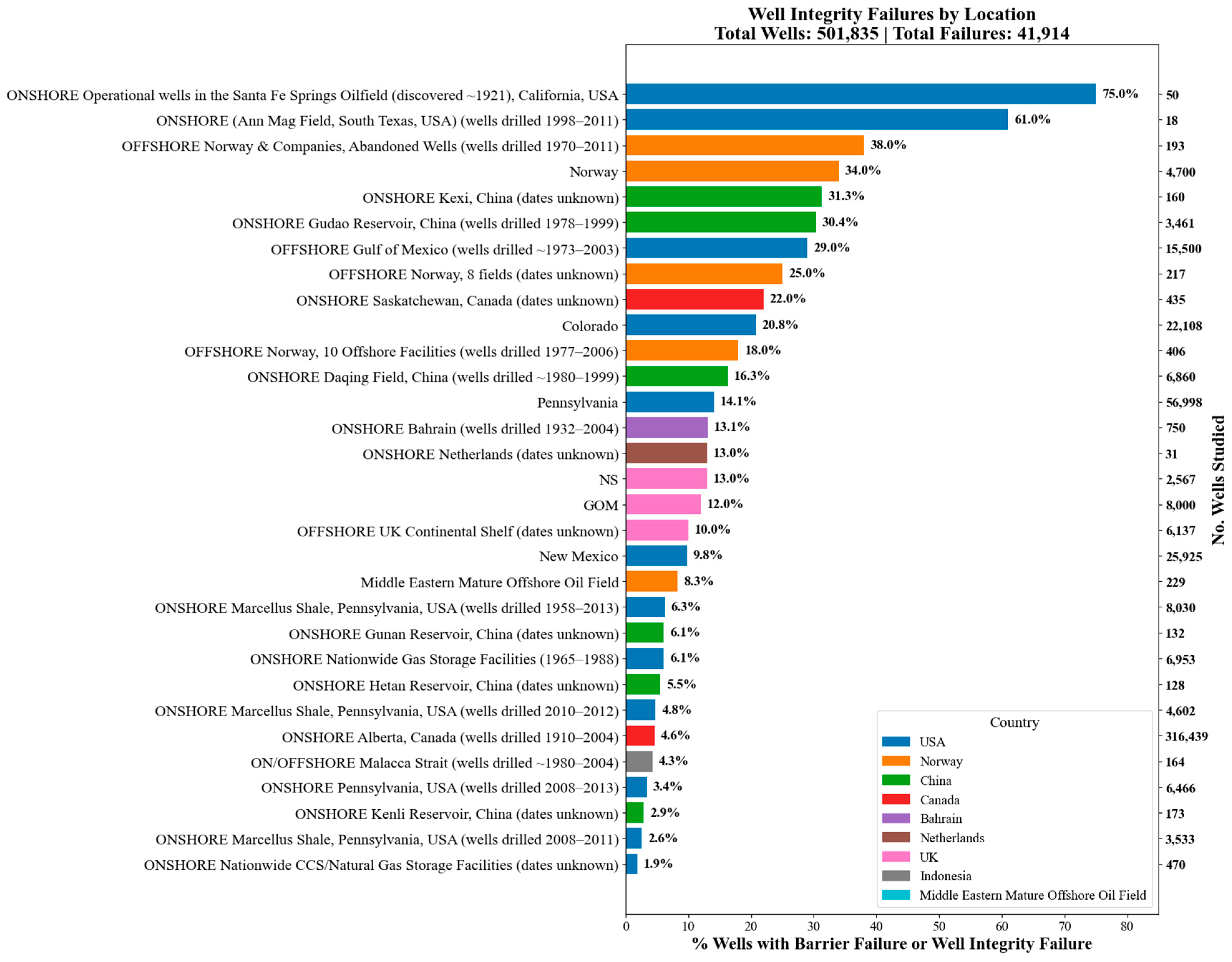
Figure 1. The percentage of wells with documented barrier or integrity failures across various global regions and well types. The total number of wells studied (501,835) and total failures (41,914) are indicated, providing a clear overview of the global well integrity challenge. The figure also highlights differences in failure rates between countries and regions, emphasizing the need for tailored P&A strategies based on specific well construction practices and geological settings. Drawn by the authors.
Energies 18 04757 g001
Figure 2. Schematic of well barrier elements and envelopes during the production phase. The primary barrier includes the tubing, packer, tubing hanger, and valves within the Christmas tree. The secondary barrier encompasses the production casing, cement, casing hanger seals, and annulus valves. This diagram also illustrates typical failure paths such as casing, tubing, and packer failures. Drawn by the authors.
Energies 18 04757 g002
Figure 3. Simplified flowchart showing the key well lifecycle phases (exploration, construction, completion, production, abandonment) with small icons representing key activities in each phase. Drawn by the authors.
Energies 18 04757 g003
Figure 4. Log-scale bar chart of well component failure frequency by well age group. Colors represent different well age groups, showing how failures cluster for certain components at particular life stages. Drawn by the authors.
Energies 18 04757 g004
Figure 10. Make-up torque versus make-up turns illustrating the engagement process of a threaded connection. Point A marks initial thread interference, B indicates the start of sealing contact, C represents initial shoulder contact, and D signifies final make-up completion. The torque components—interference torque (Tₜᵢ), sealing torque (Tₛₑ), and shoulder torque (Tₛₕ)—are derived from the incremental torque increases at each stage of engagement. Proper control of these phases is crucial to achieving reliable hydraulic and mechanical sealing without over-torque or thread damage [127]. Reproduced from [127], under the terms of the Creative Commons CC BY 4.0 license.
Energies 18 04757 g010
Figure 11. Examples of damaged casing threads. The left image shows a “jumped thread” resulting from cross-threading during make-up, while the right image illustrates a corroded and weakened connection due to prolonged exposure to harsh conditions. Both conditions pose significant risks to sealing effectiveness and long-term well integrity.
Energies 18 04757 g011
Figure 14. Finite element simulation of casing stress distribution under varying internal pressures during hydraulic fracturing. (a) Stress profile under zero internal pressure, showing residual geometry-induced stress. (b) Stress concentration at 60 MPa internal pressure indicates initial onset of hoop stress buildup. (c) Stress amplification at 120 MPa, demonstrating significant triaxial stress development and plastic deformation near casing ovalization zones. The maximum Von Mises stress observed exceeds 700 MPa, indicating potential integrity risk if not properly mitigated by design [167]. Reproduced from [167], under the terms of the Creative Commons CC BY 4.0 license.
Energies 18 04757 g014
Figure 15. Yield strength degradation with increasing temperature for different casing materials commonly used in geothermal and oil and gas wells (J55, N80, P105, and P110). Thermal exposure above 300 °C significantly reduces strength, particularly for high-strength grades like P110, necessitating careful material selection for geothermal applications [170]. Reproduced from [170], under the terms of the Creative Commons CC BY license.
Energies 18 04757 g015
Figure 16. Thermal stress evolution in casing connections during heating and cooling. At the initial state (1), the casing is in equilibrium with negligible thermal load. During the heating phase (2), axial compression develops elastically as temperature rises. When the yield strength is exceeded (3), plastic deformation or buckling may occur. During the cooling phase (4), thermal contraction generates axial tension, which can concentrate at the casing–coupling interface and risk failure. Heating induces axial compression up to the yield point, beyond which plastic deformation or buckling may occur, while cooling after thermal cycling introduces tensile stresses, risking failure at the casing–coupling interface [171]. Reproduced from [171], with permission from Elsevier.
Energies 18 04757 g016
Figure 18. Cross-sectional schematic illustrating common mechanical failure causes and resulting leakage pathways in cement sheaths. Causes include cement channels, eccentric annuli, poor cement properties, and severe temperature/pressure cycling. Leakage pathways are visualized from both side and top views, including micro-annuli, radial cracks, longitudinal fractures, and interface debonding, all of which can compromise hydraulic isolation [178]. Reproduced with permission from [178].
Energies 18 04757 g018
Figure 19. Morphology of cement sheaths under different internal pressures during hydraulic fracturing: (a) 70 MPa, (b) 80 MPa, and (c) 90 MPa. The top images (ac) show the casing–cement interface, where increasing internal pressure promotes the formation and widening of micro-annuli. The bottom images (ac) are corresponding zoomed-in cross-sectional views, showing micro-annuli widths of 117 μm, 178 μm, and 212 μm, respectively. These results demonstrate how higher internal pressures compromise zonal isolation, which is crucial for well integrity in unconventional wells [189]. Reproduced from [189], under the terms of the Creative Commons CC BY 4.0 license.
Energies 18 04757 g019
Figure 20. (A) Cement failure risk matrix illustrating the combined assessment of the likelihood of occurrence (x-axis) and severity of potential consequences (y-axis) for various cement failure scenarios in wellbores. Risk levels range from low (green) to high (red), helping prioritize mitigation strategies. Scenarios include cement sheath channeling, microannuli formation, shrinkage, contaminated slurry, improper placement, and poor mud removal. (B) Bow-tie diagram representing the central event of cement failure, with associated threats (left side) and consequences (right side). Preventive barriers (e.g., effective mud conditioning, optimized slurry design, centralizer placement) aim to prevent failure, while recovery barriers (e.g., squeeze cementing, annulus pressure monitoring) mitigate its impact. This framework provides a structured overview for managing well integrity risks related to cement performance. Drawn by the authors.
Energies 18 04757 g020
Figure 21. Evolution of cement properties post-placement showing the increase in gel strength and compressive strength. The graph highlights the “transition time” and “critical time” where the cement is most vulnerable to gas migration due to loss of hydrostatic pressure before sufficient gel strength and set strength develop [193]. Reproduced with permission from [193].
Energies 18 04757 g021
Figure 22. Numerical simulation results showing Mises stress distributions (Pa) around the casing and cement sheath in an injection well affected by fault reactivation. The shear cement strength thresholds indicate the vulnerability of the casing and cement to mechanical shear failure as the fault plane is reactivated during water injection [198]. Reproduced with permission from [198].
Energies 18 04757 g022
Figure 23. Advanced well integrity diagnostics using multiple logging technologies. (a) Multi-finger caliper log illustrating casing deformation and ovality, where deviations in the caliper traces highlight areas of potential mechanical damage; (b) noise and temperature log indicating a localized anomaly around 5970 ft consistent with a casing leak, as shown by both increased acoustic activity and temperature deviation; (c) electromagnetic multiple barrier corrosion log identifying internal and external casing corrosion and metal loss, where color variations represent differences in wall thickness and barrier condition. Together, these diagnostic logs provide a comprehensive view of barrier degradation, enabling identification of leak locations and assessment of severity. Although reproduced at the resolution available from the original source, the figure remains sufficient for conveying the diagnostic principles without impacting scientific interpretation [231]. Reproduced from [231], with permission from Elsevier.
Energies 18 04757 g023
Figure 24. Security risk mechanisms for hydrogen storage and extraction wells. The schematic highlights key integrity risks associated with hydrogen in underground storage and extraction scenarios, including: • Accumulated annular pressure, • H2 seepage and escape through well materials, • Hydrogen embrittlement and hydrogen-induced fractures/bubbles in steel casings, • Metal corrosion exacerbated by hydrogen reactions, • Elastic and sealing material failures in packers and wellhead seals, and • Cement degradation and ring seal failures in cement sheaths [26]. Reproduced from [26], under the terms of the Creative Commons CC BY 4.0 license.
Energies 18 04757 g024
Figure 25. Historical and component-specific distribution of well leakage events in underground natural gas storage (UNGS) wells. (A) Temporal distribution of leakage events from historic data and PHMSA reports, noting the 2017 PHMSA reporting requirement as a key milestone. (B) Component-specific failure counts, showing that casing and wellhead failures dominate. (C) Leakage causes, by reservoir type, highlighting the range of failure mechanisms, including corrosion, incorrect operation, and natural forces [252]. Reproduced with permission from [252].
Energies 18 04757 g025
Figure 26. Failure trends and remediation pactices in cyclic steam and SAGD wells. (Top) Historical timeline of well integrity failures in thermal EOR wells (CSS and SAGD) from 1975 to 2025, showing the frequency of incidents by year. Blue bars represent Cyclic Steam wells (CSS), while orange bars represent Steam-Assisted Gravity Drainage (SAGD) wells. (Bottom) Distribution of failure resolution strategies, where casing patching, cemented liners, and cement squeezing dominate as the most common remediation approaches. These trends underscore the persistent challenges associated with thermal cycling and the importance of robust well design and monitoring in steam injection environments.
Energies 18 04757 g026
Figure 27. The relationship between injection pressure (red line, right axis) and the number of casing damage wells (grey bars, left axis) over time from 1990 to 2015. The data highlights how sustained high injection pressures correlate with a steady increase in the number of casing damage incidents, reflecting the importance of pressure control in injection well integrity management [261]. Reproduced with permission from [261].
Energies 18 04757 g027
Figure 28. Methane emission rates and abandoned well statistics. (Top) Comparative methane emission rates and the number of unplugged versus plugged abandoned wells across selected states and regions. (Bottom) Distribution of well installation years and integrity outcomes, where blue bars represent all wells, orange bars represent tested wells, and green bars represent wells with sustained casing pressure (SCP) or casing vent flow (CVF). The red line shows the proportion of tested wells with SCP and/or CVF. These results highlight the persistence of integrity issues across installation periods. Reproduced from [268], under the terms of the Creative Commons CC BY 4.0 license.
Energies 18 04757 g028aEnergies 18 04757 g028b
Table 1. Summary table of major well integrity incidents and their key lessons learned that influenced standard/regulatory development.
Incident Name/WellLocationPrimary Suspected Cause(s)Severity/ImpactWell Control MethodKey Lessons/SignificanceReference
Lakeview Gusher #1Kern County, CA, USA Mar 1910–Sep 1911High formation pressure encountered unexpectedly; inadequate casing and early well control equipment (lack of effective BOP).Estimated 9 million barrels released; largest accidental oil spill in US history; created Lakeview pool.Eventually bridged/subsided naturally; containment dikes built.Demonstrated immense reservoir power; spurred need for better pressure control technology.[42]
Gassi Touil (GT-16 Well)Sahara Desert, Algeria Nov 1961–Apr 1962Drilling into unexpectedly high-pressure gas formation; loss of well control during drilling.Massive gas fire (“Devil’s Cigarette Lighter”), burned ~550M cubic ft/day; visible from space.Capped using explosives (Red Adair), then mechanical cap.Pioneered large-scale gas well firefighting; highlighted remote logistics challenges.[43]
Ekofisk Bravo (Platform B)Norwegian North Sea 1 April 1977Well intervention (workover). Incorrect installation of a downhole safety valve.Significant oil spill (~200k barrels); first major North Sea blowout; no fatalities.Capped by specialist team (Red Adair Co.).Led to major tightening of Norwegian regulations (NPD/Ptil); emphasized procedural discipline in well interventions.[29]
Ixtoc IBay of Campeche, Mexico June 1979–March 1980Loss of drilling mud circulation, BOP failure during drilling operations.Massive oil spill (~3.3M barrels); extensive environmental damage in Gulf of Mexico.Combination of capping attempts and relief wells.Highlighted deepwater well control challenges, environmental impact, BOP reliability.[44]
Piper Alpha(Tucker, 2016)Production platform disaster. Gas leak during maintenance; failure of permit-to-work and safety systems; design flaws exacerbated fire spread.Catastrophic fire/explosion; 167 fatalities; total platform destruction.N/A (Platform destroyed)Fundamentally changed offshore safety culture. Led to “Safety Case” regime (risk assessment, management systems). Not a drilling blowout, but profoundly influential.[45]
Sidoarjo Mud Flow (Lusi)East Java, Indonesia May 2006–OngoingHighly Debated. Linked by many studies to drilling operations (kick/underground blowout) at Banjar Panji-1. Others cite preceding earthquake.Ongoing mud volcano eruption; >60k displaced; vast areas inundated; long-term environmental/social disaster.Failed plugging attempts; containment levees; flow continues.Highlights potential links between drilling and geology; catastrophic long-term impact; site assessment importance; remediation difficulty.[46]
Montara Wellhead PlatformTimor Sea, Australia August–November 2009Failure of cemented primary barrier (casing shoe); failure of secondary barrier (corrosion cap); poor well construction/suspension practices.Uncontrolled release (74 days); significant oil spill (~30k–40k barrels); environmental impact concerns.Relief well intervention (West Triton rig).Highlighted operator oversight failures, well integrity management issues, regulatory gaps. Led to reforms (NOPSEMA establishment).[32]
Macondo (Deepwater Horizon)Gulf of Mexico, USA April–July 2010Complex cascade: Cement integrity failure, pressure test misinterpretation, kick detection delays, BOP failure (Blind Shear Ram functionality).11 fatalities; largest marine oil spill (~4.9M barrels); extensive environmental/economic damage.Capping, followed by relief wells (“Static Kill” and “Bottom Kill”).Major overhaul of US offshore regulations (BSEE formation); focus on deepwater well control, cementing, risk management, BOP reliability and testing.[47]
Elgin PUQ Gas LeakUK North Sea March–May 2012Well integrity failure. Annular pressure buildup (casing failure/corrosion) in a production well led to surface leak.Major gas leak; prolonged evacuation; large exclusion zone; complex well kill. High ignition potential.Dynamic kill (heavy mud from adjacent rig), then cementing.Highlighted challenges of aging assets, HPHT wells, annulus pressure management, long-term well integrity monitoring.[48]
Pryor Trust Gas Well BlowoutPittsburg County, OK, USA 1 January 2018Loss of well control during tripping; potential issues with BOP activation/effectiveness.Rig fire; 5 fatalities.Well capped after fire extinguished by specialists.Reinforced importance of primary control (mud), trip procedures, BOP functionality/testing, crew response, even onshore.[49]
Disclaimer/Publisher’s Note: The statements, opinions and data contained in all publications are solely those of the individual author(s) and contributor(s) and not of MDPI and/or the editor(s). MDPI and/or the editor(s) disclaim responsibility for any injury to people or property resulting from any ideas, methods, instructions or products referred to in the content.