Article

Using Ultrasonic Fuel Treatment Technology to Reduce Sulfur Oxide Emissions from Marine Diesel Exhaust Gases

1
Department of Ship’s Power Plants, National University Odessa Maritime Academy, Didrikhson Str. 8, 65029 Odessa, Ukraine
2
Denube Institutes, National University Odessa Maritime Academy, Fanagoriyska Str. 9, 68600 Izmail, Ukraine
*
Author to whom correspondence should be addressed.
Energies 2025, 18(17), 4756; https://doi.org/10.3390/en18174756
Submission received: 12 July 2025 / Revised: 24 August 2025 / Accepted: 4 September 2025 / Published: 6 September 2025

Abstract

This paper discusses the use of additional ultrasonic fuel treatment technology to reduce sulfur oxide emissions from marine diesel exhaust gases. The research was conducted on a Bulk Carrier vessel with a deadweight of 64,710 tons with the main engine YMD MAN BW 6S50ME-C9.7 and three auxiliary diesel generators CMP-MAN 5L23/30H. The exhaust gases from all engines were treated for sulfur impurities using a scrubber system. It was stated that the combined use of the exhaust gas scrubber system and ultrasonic fuel treatment technology (compared to scrubber-only exhaust gas cleaning) results in a reduction in carbon dioxide CO2 and sulfur dioxide SO2 emissions, along with their ratio SO2/CO2. The additional ultrasonic fuel treatment technology has had the most significant effect on sulfur-containing components, leading to a substantial decrease in SO2 emissions from exhaust gases. For various operating conditions of ship diesel engines, a reduction in CO2 emissions of 2.9–7.5% and a reduction in SO2 emissions of 9.3–33.1% were established. This achieved a reduction of 6.3 to 23.7% in the SO2/CO2 ratio, a critical parameter for evaluating the performance of the scrubber system in exhaust gas cleaning, as mandated by the provisions of Annex VI of MARPOL. The requirements of the international conventions MARPOL and SOLAS were adhered to during the experiments.

1. Introduction

Maritime transport keeps a leading position among all modes of transportation. The volume of cargo transported by sea significantly exceeds that of other transport modes—road, rail, and air [1,2,3]. Modern ships of the Bulk Carrier class have a transport capacity of up to 200,000–220,000 tons of bulk cargo. The deadweight tonnage of Crude Oil class tankers, which are specifically designed for the transportation of crude oil, reaches between 250,000 and 280,000 tons. The volume capacity for liquefied natural gas or liquefied petroleum gas, transported by LNG/LPG class tankers, exceeds 250,000 cubic meters in certain cases. Ro-Ro vessels, designed for wheeled cargo, are capable of carrying between 6500 and 7000 vehicles per voyage, ranging from passenger cars to trucks. Modern container ships can accommodate up to 22,000 to 23,000 twenty-foot equivalent units (TEUs). Passenger and cruise ships have the capacity to accommodate more than 6000 passengers, supported by a crew complement of between 2200 and 2500 individuals.
Other vessel types include General Cargo, Heavy Lift Carriers, Reefers, and Lighter Aboard Ships, designed for general, heavy, refrigerated, and lighter cargo, respectively. Additionally, Platform Supply Vessels, Anchor Handling Tug Supply Vessels, and Dredgers support offshore oil platforms, anchor handling, and dredging operations [4,5,6]. These advancements highlight the evolution and refinement of marine vessels and their power plants.
Maritime transport relies on mechanical energy from heat engines [7,8]. The main source of mechanical energy on ships is internal combustion engines (ICE) [9,10,11], being the most common type of heat engine in marine power plants [12,13].
Currently, ICEs are installed on all marine vessels without exception, serving as either main or auxiliary engines. As main engines, they transmit torque to the ship’s propeller (fixed or controllable pitch) to enable propulsion [14,15,16]. As auxiliary engines, their effective power is converted into electrical energy by ship generators, which power auxiliary machinery, deck and navigation equipment, and lighting as well [17,18,19].
The primary fuel for all marine heat engines—diesel engines, boilers, and gas turbines [20,21]—remains liquid petroleum fuel [22,23]. The use of gaseous fuel in marine diesel engines is still limited and experimental (though the number of such vessels is gradually increasing) [24,25]. Even fewer ships are equipped with power plants using methanol or ethanol [26,27]. Biofuels (typically Fatty Acid Methyl Esters, or FAME) have low stability, requiring their blends with petroleum-based fuels to be used shortly after preparation [28,29]. This limits their use during long sea voyages. Additionally, the warranty lifespan of marine diesel engines reaches 20–25 years, ensuring demand for liquid fuel over this period.
Fuels used in marine ICEs are classified according to the international standard ISO 8217, Petroleum Products—Fuel (Class F) specifications of marine fuels [30]. This document defines the main types of marine fuel as follows: Heavy Fuel Oil (HFO) as the main fuel for engines, Marine Diesel Oil (MDO) as additional fuel for engines, and Marine Gas Oil (MGO) as a reserve fuel [31,32].
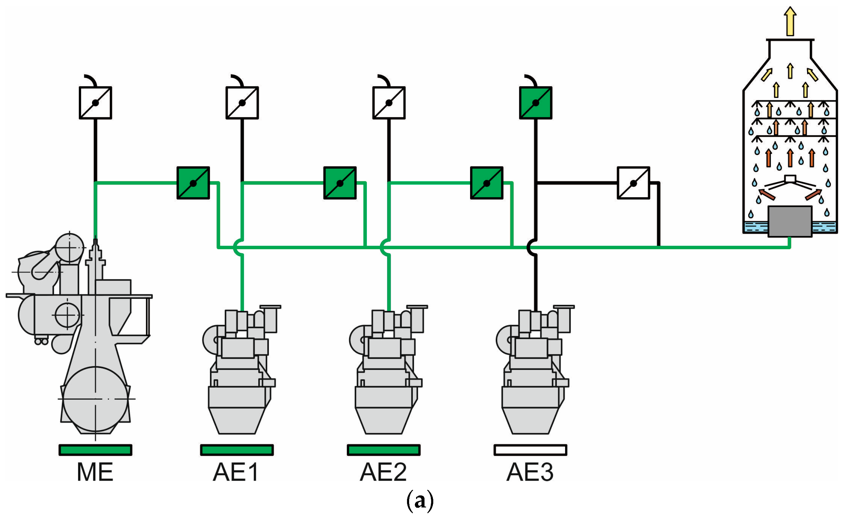
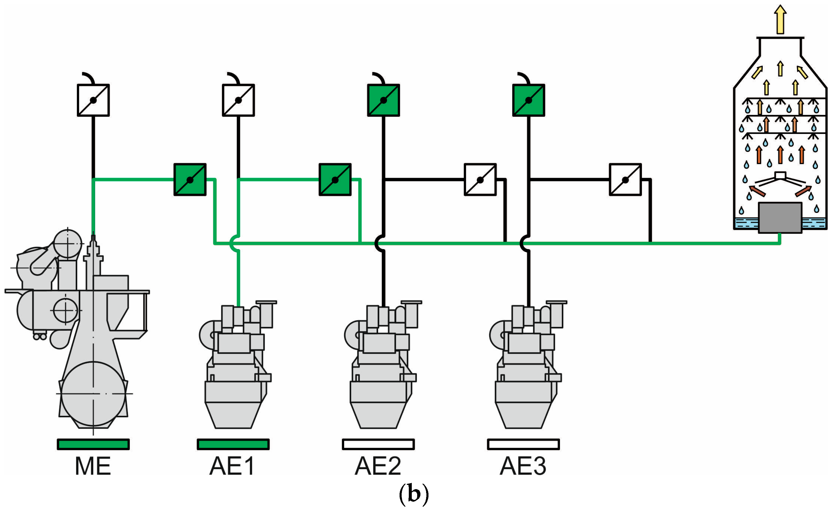
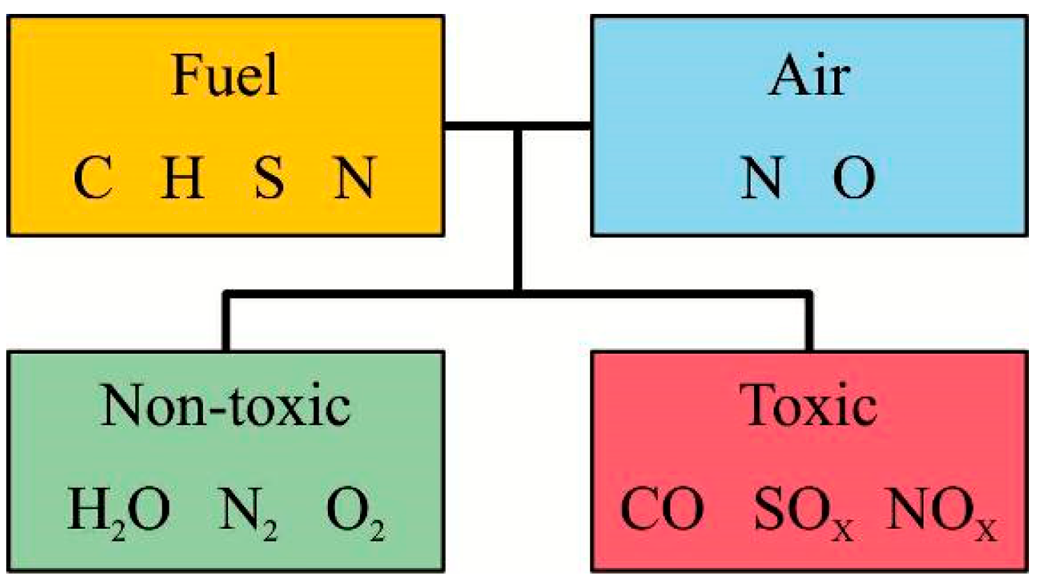
Combustion in marine diesel engines not only generates kinetic energy (converted into torque) but also produces exhaust gases emitted into the atmosphere. Carbon, hydrogen, sulfur, and nitrogen (present in petroleum-based fuels) oxidize with the air (containing nitrogen and oxygen) during combustion, forming a complex multicomponent mixture. Alongside neutral and harmless substances (e.g., water vapor H2O, residual oxygen O2, and nitrogen N2), this mixture contains toxic compounds like nitrogen oxides NOX, sulfur oxides SOX, and carbon monoxide CO (Figure 1) [33,34,35].
These substances negatively impact the environment and human health, so their emission level is continuously monitored and restricted due to the requirements of international and national conventions [36,37].
Emission control is regulated internationally, particularly by the MARPOL 73/78 Convention, which is the primary international document for environmental protection and the prevention of marine pollution during the operation of vessels [38,39,40].
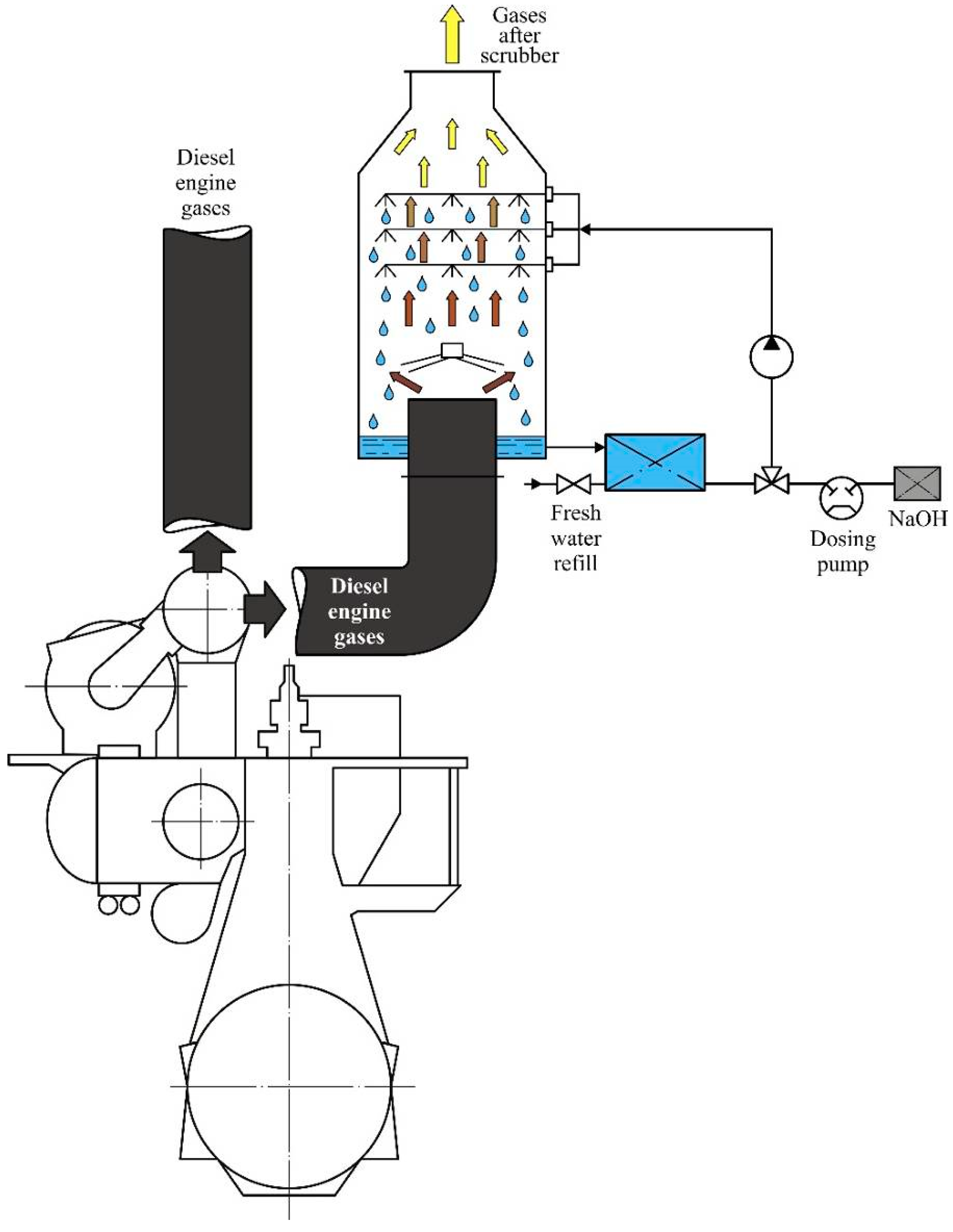
Annex VI MARPOL mandates the sulfur content in fuel to not exceed 0.1% in Sulfur Emission Control Areas (SECAs) or 0.5% outside these zones [41,42]. When a vessel’s power plant is additionally equipped with an exhaust gas cleaning system (the most common being scrubber systems, as shown in Figure 2), the diesel engines may operate using fuel with a sulfur content of up to 3.5% [29,43]. In such cases, equivalence between the SO2/CO2 emission ratio and the sulfur content in marine fuel must be demonstrated (Table 1).
Therefore, when a vessel is equipped with an additional exhaust gas scrubber system while using fuel with elevated sulfur content (up to 3.5% by mass), the SO2/CO2 emission ratio must not exceed 21.7 when operating outside of SECAs, and must remain below 4.3 when operating within SECAs.
Marine diesel engines utilize fuels with a sulfur content not exceeding 0.2 to 0.25% and a viscosity not exceeding 150 sSt; these fuels are classified as Very Low Sulfur Fuel Oil (VLSFO). Fuels with a viscosity of 380 sSt or greater are more commonly used on seagoing vessels and are categorized as IFO380. The sulfur content in such fuels may exceed 0.5%. The cost of fuel varies depending on its operational characteristics. As of 1 April 2025, fuel prices in various world ports (according to the Internet resource Ship & Bunker—Shipping News and Bunker Price Indications) are shown in Table 2.
Taking into account the data shown in Table 2, fuel costs for powerful ship power plants reach 300–320 thousand USD/day, and for medium-powered ship power plants—70–75 thousand USD/day. The given data explain the desire of shipowners to reduce fuel costs due to the purchase of fuel with a deteriorated fractional and structural composition, as well as the use of similar fuels in the operation of marine diesel engines (two-stroke and four-stroke) at any load [45,46,47].
The use of VLSFO fuels, and especially MGO, reduces the economic efficiency of sea transport vessels. This is one of the reasons for employing scrubber systems for exhaust gas cleaning, which allow the use of fuel with a sulfur content of up to 3.5% [48,49].
Contemporary strategies for reducing SOX emissions include the utilization of alternative fuels characterized by minimal sulfur content (not exceeding 0.02–0.03% by mass) or the complete absence of sulfur. Natural gas [45] constitutes the predominant category of such fuels. However, its application is largely restricted to Gas Carrier vessels transporting liquefied natural gas (LNG), whereby part of the evaporated cargo is used as fuel for the diesel engines.
Post-combustion treatment technologies also contribute to the mitigation of sulfur oxide emissions [46]. Although widely employed in stationary power generation, their implementation on marine vessels remains limited, as regulatory frameworks governing SOX emission control during such applications have not yet been ratified by the International Maritime Organization.
The most effective approach to curtail sulfur oxide emissions from exhaust gases involves their purification through scrubber systems. Complementarily, fuel desulfurization—a technological procedure aimed at removing a fraction of sulfur from the fuel—further facilitates the reduction in sulfur oxide concentrations in the exhaust. Principal desulfurization techniques include dynamic filtration [47], hydrodesulfurization, phase-transfer catalysis [48], and oxidative desulfurization [49], as well as desulfurization employing nanocoatings [50] and nanoadditives [51].
While these technologies are well-established within fuel production and the enhancement of fuel performance characteristics, their practical application onboard marine vessels is constrained by several limiting factors. Dynamic filtration necessitates high-power equipment prone to elevated vibration levels, thereby imposing additional acoustic burdens on personnel. Hydrodesulfurization requires supplementary storage tanks for both pure water, which is utilized in the fuel treatment process, and contaminated water harboring residual substances extracted from the fuel. The oxidative desulfurization process involves the handling and storage of hazardous reagents, which entails significant safety risks within the confined and restricted spatial environments of ships. Additionally, technologies based on nanocoatings and nanoadditives suffer from diminished efficiency due to periodic surface fouling and continuous fuel volume fluctuations in settling and service tanks.
An additional approach to reducing the sulfur content in fuel—and consequently decreasing sulfur oxide emissions in exhaust gases—is the application of ultrasonic wave irradiation to the fuel.
Ultrasonic fuel treatment promotes the dissociation and breaking of intermolecular bonds in sulfur–sulfur S–S, carbon–sulfur C–S, and carbon–hydrogen C–H compounds. This occurs due to the thermal decomposition of these compounds during ultrasonic fuel processing [52,53]. Subsequently, the “free” sulfur (S) reacts with hydrogen (H), which is a component of the fuel. As a result, hydrogen sulfide H2S is formed on the exposed fuel surface. Its concentration remains at a safe level for both humans and fuel system components. Research [12,21,54] has confirmed that the concentration of hydrogen sulfide in the air above the exposed fuel surface does not exceed 0.03–0.032 mg/m3 (with a maximum permissible concentration of 3 mg/m3). During ultrasonic fuel treatment, hydrogen sulfide is removed from the exposed fuel surface by the ship’s ventilation system.
Typically, fuel desulfurization using ultrasound is examined from the perspective of reducing sulfur-induced wear in the cylinder liner’s upper part, piston rings, exhaust valves, and maintaining the technical condition of the diesel engine’s cylinder group and exhaust gas system. However, significantly less attention has been paid to studying the effect of fuel desulfurization on the environmental performance of marine diesel engines. Furthermore, there is a notable lack of research comprehensively investigating the combined impact of fuel desulfurization and exhaust gas cleaning systems on sulfur oxide SOX emissions.
The aforementioned technologies contribute significantly to the reduction in sulfur oxide SOx emissions. However, the combined effect of ultrasonic fuel treatment and scrubber-based exhaust gas cleaning on the environmental performance of marine vessels—particularly in relation to sulfur oxide emissions—has been insufficiently explored. This integrated approach constitutes a two-stage process for mitigating sulfur oxide emissions. The first stage involves fuel desulfurization through ultrasonic irradiation, while the second stage comprises the direct purification of exhaust gases from sulfur-containing compounds. The majority of existing studies do not address this combined methodology, which results in comparatively lower reductions in SOx concentrations in exhaust gases and necessitates reliance on more costly fuel grades.

2. Literature Review

The operation of marine diesel engines is impossible without specialized mechanical systems that supply fuel and air to the cylinders, remove exhaust gases, provide lubrication to the cylinder group and crankshaft, and deliver seawater and freshwater for cooling the cylinder liner, cylinder head, and charge air [53,54].
The most complex of all engine systems is the fuel system. Typically, it consists of subsystems for storage, transfer, separation, and high-pressure fuel injection. Throughout the fuel’s “life cycle” (from entry into settling tanks to injection into the combustion chamber), its physicochemical characteristics—primarily temperature, density, viscosity, water content, and mechanical impurities—constantly change [55,56]. To stabilize these parameters, heating, settling, filtration, and separation are used, which also help remove water and mechanical contaminants from the fuel.
In marine vessel operations, sulfur reduction in fuel is achieved through additional treatments such as fine filtration, hydrodynamic cleaning, cavitation, and ultrasonic treatment [57,58]. While these methods effectively remove sulfur, they nevertheless present certain limitations. The use of fine filtration necessitates the installation of filters in fuel lines with micron-rated mesh sizes that increase hydraulic resistance [59]. The reduced flow area accelerates the accumulation of mechanical, organic, and inorganic impurities on filter surfaces, more frequent cleaning is needed—often manually rather than automatically [60,61]. Additionally, fine filtration removes combustible fuel components, particularly carbon, reducing its calorific value.
Hydrodynamic cleaning involves mixing fuel with distilled water, followed by hydrodynamic treatment, settling, and separation. During this process, some sulfur reacts with water, forming salts that are removed. However, this method requires disposal of sulfur-containing salt residues and consumes significant amounts of energy [62,63].
Cavitation treatment subjects fuel to variable high pressures, while ultrasonic treatment uses specific-frequency sound waves. Both methods remove sulfur compounds either through precipitation or evaporation from the fuel’s surface [64,65].
The most intensive research and development in marine fuel desulfurization occurred when engines could still use high-sulfur fuel (up to 3.5%). During that period, homogenization, cavitation, and ultrasonic treatment were the primary methods for reducing sulfur oxide emissions. However, the main goal was not emission reduction but mitigating sulfuric acid corrosion in cylinder groups and exhaust tracts. This corrosion resulted from reactions between unburned sulfur compounds and water vapor in scavenge air, particularly problematic in four-stroke engines without dedicated cylinder lubrication systems. In such engines, a common circulating lubrication system serves both cylinders and crankshafts, often inadequately neutralizing the sulfuric acid formed [21,66].
Nowadays, standalone fuel desulfurization has lost relevance due to stricter sulfur limits under Annex VI MARPOL (max 0.5%) [38,67]. While reducing sulfur from 3.2 to 3.4% to 2.3–2.5% was once considered significant, such methods are now obsolete. Currently, sulfur oxide SOX emission control is predominantly achieved through exhaust gas scrubbers [68,69]. These devices are installed in the exhaust gas system of marine diesel engines (see Figure 1), and exhaust gases are specifically routed through them when purification is required.
The following main methods of scrubber cleaning of exhaust gases are used on seagoing vessels.
Open-Loop Seawater Scrubber
The scrubber operates on open-loop technology (see Figure 3). In such a system, seawater is taken directly into the scrubber and, after the cleaning process, passes through water treatment before being discharged back to the sea. The primary role of the scrubber is to reduce SOX emissions to below 0.1% [70,71,72].
The open-loop method has several benefits. It does not require additional tanks or auxiliary units, which minimizes space demand. Moreover, there is no need for a monitoring unit for NaOH injection. Operating costs are also low, since the system relies on relatively few components.
An open-loop scrubber removes about 95% of SOX from exhaust gases. However, a major drawback is that residual pollutants remain in the discharged water, which returns untreated to the sea. This becomes a concern particularly in harbor areas.
Closed-Loop Freshwater Scrubber
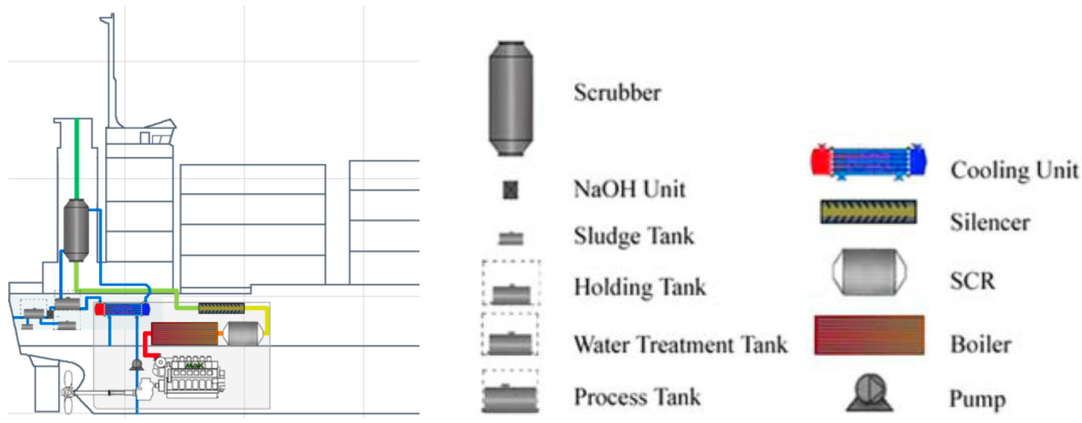
In closed-loop technology, as shown in Figure 4, no water is taken directly from the sea. The freshwater comes from a buffer tank and is cooled by seawater. This freshwater contains NaOH and is pumped from the buffer tank to the scrubber. After the scrubbing process, the water returns to the buffer tank, where it is cleaned by a filter. The contaminated water moves to a sludge tank, while the treated water re-enters the scrubbing cycle. A large storage tank is used to refill the buffer tank. The primary function of a scrubber is to reduce SOX emissions below the threshold of 0.1% [70,73,74].
Using closed-loop technology provides certain advantages. First, the pH level can be increased to achieve further SOX reduction. Additionally, the system avoids corrosion of the components and produces less discharge water that requires treatment. However, the operating costs of closed-loop technology are relatively high because NaOH is consumed. The sludge tank must also be emptied in port, which adds significant expenses. Another drawback is the requirement for additional tanks, which occupy considerable space on board.
A closed-loop scrubber removes about 98% of SOX from exhaust gases. Compliance with IMO Tier III standards 2016 does not pose major challenges; however, applying closed-loop technology outside SECAs is generally considered unnecessary and cost-prohibitive.
Hybrid System
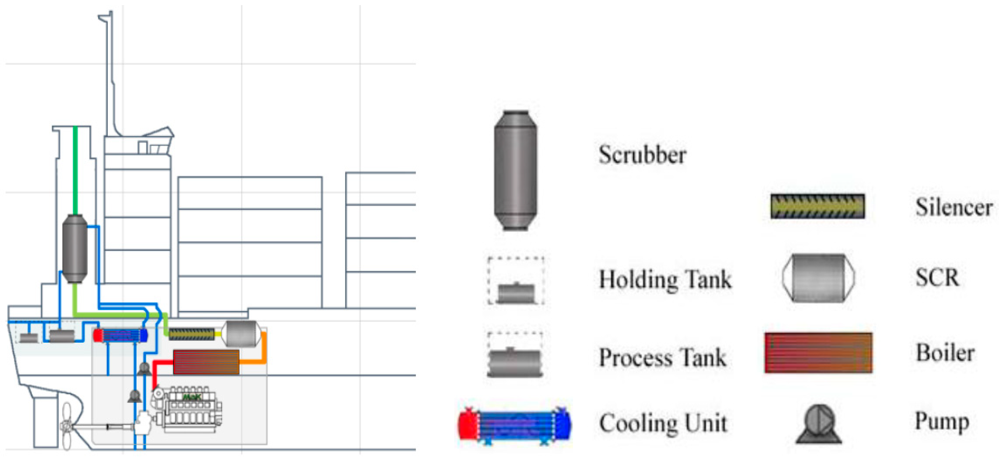
The scrubber operates as a hybrid system (see Figure 5). A hybrid system combines both open-loop and closed-loop modes. In harbors and SECAs, the unit can function with freshwater, generating only a minimal amount of sludge to be handled at port calls. In open seas, the system switches to seawater in the open-loop mode. The primary role of the scrubber is to reduce SOX emissions below the regulatory threshold of 0.1% [70,75,76].
The placement of the scrubber in the funnel area was determined by the lack of available space in the engine room. Another issue involved the pipe arrangement, as the scrubber is positioned at the end of the system. This configuration cools the exhaust gases, resulting in a noticeable pressure drop of 9.8 mbar. Due to the limited engine room space, some components had to be installed on the deck above the engine room, where the freshwater tank is usually located. The major drawback of this design is reduced vessel stability, as the scrubber and its associated parts add considerable weight [77,78].
Additional fuel treatment using ultrasonic waves can be applied at various sections of the fuel system. This is schematically illustrated in the process diagram provided in Figure 6.
The system functions as follows. During bunkering operations, fuel is delivered through pipeline 1 to the receiving tank (2), which incorporates heating from an external thermal source (typically steam). The fuel is then transferred to the vessel’s engine room via transfer pumps (3), which direct the fuel to the settling tanks (4). Fuel preliminary preparation is carried out in the tanks (4) (where fuel sedimentation and preliminary removal of water/mechanical impurities are provided); in heaters (5) (which maintain the required fuel temperature); separators and filters (6 and 7, respectively) (which are used for final water and particles removal). After that, the fuel enters the daily service tank (8) and is subsequently delivered to the diesel engine (11) by means of booster pumps (9) via a fuel pre-heater (10) (which maintains not only optimal temperature but viscosity parameters as well).
The recommended zones for ultrasonic fuel treatment are designated as I, II, III, IV, and V.
The first and second sections of the fuel system where ultrasonic fuel treatment can be applied are as follows: the fuel transfer line delivering fuel from the receiving tank (designated as I in Figure 6) or the fuel settling tank (designated as II in Figure 6). In these sections, ultrasonic waves activate the breakdown of heavy sulfur-containing compounds in the fuel that has not yet undergone any treatment or purification. Since the fuel at this stage still contains water and mechanical impurities, this reduces the intensity of the ultrasonic waves and consequently decreases the efficiency of the fuel desulfurization process. An additional drawback of ultrasonic fuel treatment in these sections (particularly in Section I—the fuel transfer line) is the necessity to monitor sediment formation resulting from the removal of sulfur-containing components from the fuel flow [79,80]. Due to the increased density of these compounds and the presence of mechanical impurities and water in the fuel, sediment accumulation occurs more intensively in this specific section compared to other parts of the fuel system [81,82].
These deficiencies are eliminated in the third and fourth treatment zones (designated III and IV in Figure 6), which are recommended for ultrasonic fuel treatment. These sections correspond to fuel that has already undergone heating, separation, and filtration (handled by components 5, 6, and 7 in Figure 6). As a result, the ultrasonic waves act directly on the sulfur-containing compounds, significantly improving the fuel desulfurization efficiency in these parts of the fuel system. However, similar to the desulfurization process in Section I, it is necessary to monitor the condition of the fuel lines, as sediment buildup can degrade their performance [83,84]. During ultrasonic treatment in the daily service tank, desulfurization occurs through the removal of fuel vapors containing sulfur compounds [85,86]. This reduces the accumulation of heavy sediment, including sulfur [87,88].
Experimental studies have confirmed that the most effective location for ultrasonic treatment is the pipeline section preceding the diesel engine’s high-pressure fuel injection system (position V in Figure 6). In this part of the fuel system, the fuel reaches maximum temperature and minimum viscosity, which enhances the efficiency of sulfur impurity removal [80,89,90]. Some studies have also proposed using a comprehensive ultrasonic fuel desulfurization system [91,92,93]. The first stage involves ultrasonic treatment in the daily service tank (position IV in Figure 6), while the second stage consists of ultrasonic treatment before the high-pressure fuel injection system (position V in Figure 6). The first stage facilitates preliminary sulfur removal from the fuel, while the second stage ensures breakdown of sulfur-containing components and their activation before entering the diesel engine’s combustion chamber.
This information provided confirms that currently, the primary method for complying with MARPOL Annex VI requirements regarding SOX concentration in exhaust gases when using fuel with sulfur content up to 3.5% is scrubber cleaning. Therefore, direct fuel desulfurization processes should be considered in conjunction with the main technology for reducing sulfur oxide emissions—exhaust gas cleaning in marine scrubbers [94,95,96].
Taking into consideration all information provided above, the research objective was to determine the effect of additional ultrasonic treatment of high-sulfur marine fuel on sulfur oxide emissions in exhaust gases, which are cleaned from sulfur compounds using a scrubber system.

3. Materials and Methods

The motivation for the conducted research was the task of finding methods for the additional reduction in sulfur oxide emissions from the exhaust gases of marine diesel engines [97,98,99]. This task gains additional relevance when marine vessels are in special emission control areas, as well as in cases of sudden load increases in ship diesel engines (main and auxiliary)—specifically, in the exhaust gas cleaning system for the removal of sulfur impurities. These cases may arise when there is a need for urgent vessel speed increase (which increases the load on the main engine and accordingly increases the amount of exhaust gases entering the scrubber cleaning system), as well as due to forced load increases on ship auxiliary engines. The latter occurs when activating equipment that ensures vessel maneuvering capabilities (for example, thruster devices), equipment that maintains working and rest conditions for the ship crew (for example, comfort air conditioning systems), as well as for ensuring other technological operations and living conditions.
The research cycle to determine the effect of additional ultrasonic fuel treatment on changes in sulfur oxide emissions during scrubber cleaning of marine diesel exhaust gases was conducted on a Bulk Carrier class vessel with a deadweight of 64,710 tons. The vessel’s power plant consisted of the main engine YMD MAN B&W 6S50ME-C9.7 (Yichang Marine Diesel Engine Co., Ltd., Yichang City, Hubei Province, China) and three auxiliary diesel generators CMP-MAN 5L23/30H (CSSC Marine Power Co., Ltd. Zhenjiang, Jiangsu, China). The main characteristics of the vessel, main engine, and auxiliary diesels are given in Table 3.
The main and auxiliary diesel engines operated on two fuel grades: RMG380 and DMA10. The key fuel characteristics are presented in Table 4.
DMA10 fuel was used during starting of the diesel engines (both the main engine YMD MAN-B&W 6S50ME-C9.7 and the auxiliary engines CMP MAN-B&W 5L23/30H), as well as during the reversing of the main engine YMD MAN-B&W 6S50ME-C9.7. RMG380 fuel was used during all other operational modes.
Compliance with MARPOL Annex VI requirements regarding sulfur oxide emissions was ensured by the SOX exhaust gas cleaning system [100]. This system cleaned the exhaust gases from the diesel engines (both main and auxiliary) to remove sulfur compounds [101,102,103].
The scheme of the scrubber system for cleaning exhaust gases is shown in Figure 7.
The exhaust gas cleaning system (EGCS) installed on the vessel is a wet-type system with an open loop. The EGCS uses seawater to reduce sulfur oxides SOx emissions with the exhaust gases of the main and auxiliary engines. The seawater, which initially enters the Kingston box, is directed to the DeSOx exhaust gas desulfurization tower. In the DeSOx tower, seawater is sprayed at the upper part and moves downward—against the flow of the exhaust gases. This causes the mixing of water droplets with the exhaust gases, which ensures the removal of sulfur oxides SOx from the exhaust gas stream. After contact with the exhaust gases, the pH level of the seawater decreases, indicating an increase in its acidity. Therefore, before discharging the water from the system, an additional amount of seawater is added to its flow directly from overboard. This raises the pH level to the necessary value.
The main components of the EGCS and their functions are as follows:
SW pump—provides the supply of seawater from the Kingston container to the upper part of the DeSOx exhaust gas desulfurization tower.
SW filter—cleans seawater from organic and inorganic impurities, as well as small living organisms that may be present in the seawater. This prevents clogging of the spray nozzles through which seawater is injected into the exhaust gas stream in the DeSOx desulfurization tower. In case of increased contamination, the filter automatically performs backwashing. Contaminants accumulated in the filter are returned to the sea.
In the DeSOx desulfurization tower (or SOx scrubber), seawater is sprayed into the exhaust gas stream. The exhaust gases, thus cleaned, enter the gas exhaust pipe and are discharged into the atmosphere. Seawater flows to the lower part of the DeSOx tower and is then discharged overboard.
Static mixer—provides the mixture of the water coming from the DeSOx desulfurization tower with seawater supplied by the buffer pump. This maintains the required pH level of the water that is discharged overboard after exhaust gas cleaning.
Buffering pump—provides the supply of seawater to the static mixer.
The EGCS is also equipped with the following additional equipment:
De-gas unit (seawater de-gasser)—provides the removal of exhaust gas bubbles that may be present in the wash water;
Wash water filtration system—provides the removal of solid compounds that enter the wash water from the exhaust gases;
Thermal Transient Shock Mitigation System—provides cooling of exhaust gases and reduces their temperature before startup and during the initial operation of the EGCS. [100].
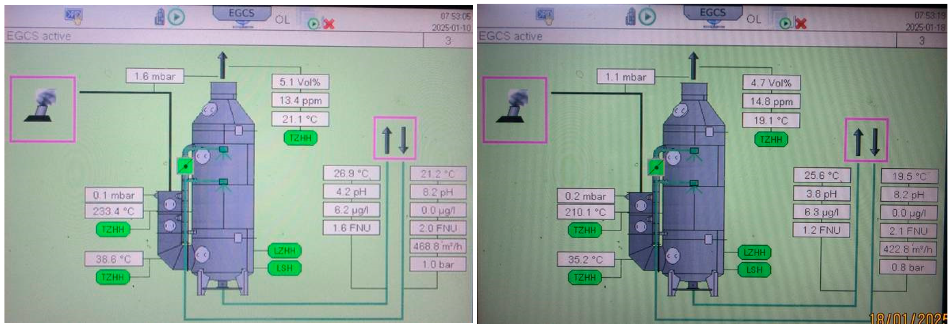
The EGCS was operational across a wide range of operating modes: from minimum load mode (corresponding to 25% power of one auxiliary engine CMP MAN-B&W 5L23/30H) to maximum mode (corresponding to simultaneous operation of the main engine YMD MAN-B&W 6S50ME-C9.7 at 85% power and three auxiliary diesel engines CMP MAN-B&W 5L23/30H each at 75% power). The EGCS could operate in these modes, as well as in all other modes, which are higher than minimum and lower than maximum, for an unlimited time period. The EGCS also allows for short-term operation (not exceeding 1 h) in a mode corresponding to a 105% load on the main engine YMD MAN-B&W 6S50ME-C9.7 and a 150% total load on the auxiliary engines CMP MAN-B&W 5L23/30H. A visualization of some of the EGCS operational mode controls is shown in Figure 8.
The main indicators determined during the operation of the EGCS were as follows:
  • The pressure (mbar) and temperature (°C) of the exhaust gases before the scrubber;
  • Carbon dioxide CO2 content (% v) and sulfur dioxide SO2 content (ppm) after the scrubber;
  • Temperature (°C), acidity (pH), turbidity (μg/L), flow rate (m3/h), and pressure (bar) of seawater before the scrubber;
  • Temperature (°C), acidity (pH), and turbidity (μg/L) of seawater after the scrubber [104,105,106].
The visualization of some operational mode indicators of the EGCS is shown in Figure 9.
The security features of the monitoring software (responsible for EGCS operation visualization) restricted screenshot taking and data printing. As a result, the data presented in Figure 8 and Figure 9 were acquired as photographs of the monitor screen.
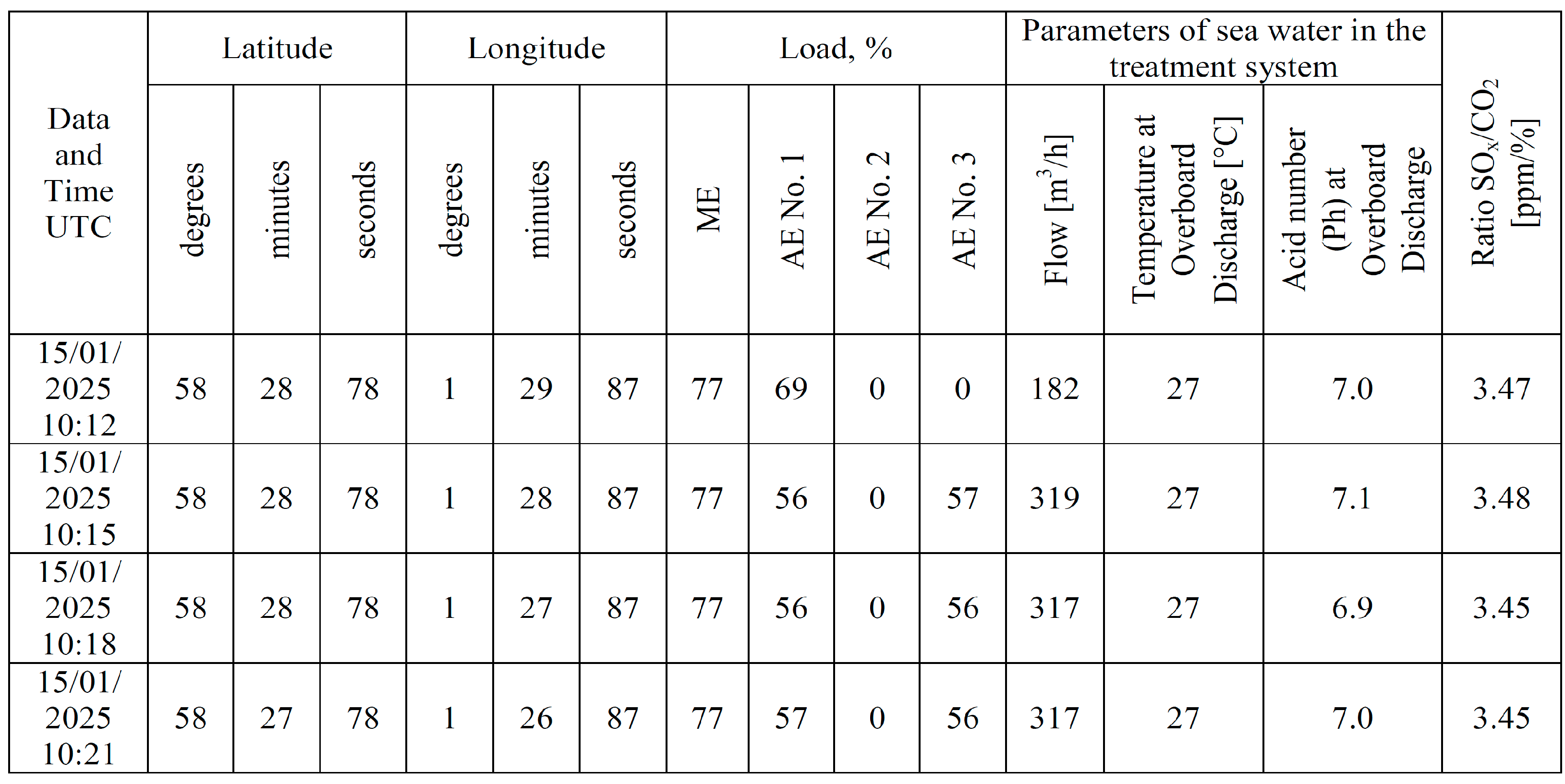
The EGCS software (with Windows 11) provided automatic recordings of the following parameters:
  • Vessel location (in latitude and longitude, degrees/minutes/seconds format);
  • The load of the main engine and auxiliary engines (in Load, ME, AE No. 1, AE No. 2, AE No. 3 format);
  • Seawater parameters in the cleaning loop;
  • Current values of sulfur dioxide SO2 and carbon dioxide CO2 emissions, as well as their SO2/CO2 ratio.
These operating parameters were recorded at 3 min intervals. A fragment of the recording table is shown in Figure 10.
As an additional fuel preparation method to ensure its desulfurization and thereby contribute to the reduction in SOX emissions in exhaust gases, ultrasonic fuel treatment was selected [51,107,108]. At the same time, the fuel subjected to ultrasonic treatment was pre-conditioned through all primary preparation stages, including settling, separation, and filtration. This pre-treatment enhanced the efficiency of ultrasonic processing and specifically targeted the sulfur-containing components of the fuel, which, unlike water and mechanical impurities, are not removed by settling, separation, or filtration.
The source of ultrasonic waves was the PLS-QXDY3000W ultrasonic generator from Foshan Pulisonic Ultrasonic Technology Co., Ltd. (601, Building 1, Shiyou Manufacturing Park, Jun’an Town, Foshan, Guangdong, China). As in most cases connected with ultrasonic treatment, the primary function of the ultrasonic generator was to produce ultrasound waves at frequencies where the disruption of internal bonds within the treated medium occurs. In the context of fuel treatment, this manifests as the breaking of long molecular chains and the disruption of intermolecular bonds among sulfur-containing components. Ultrasonic treatment also contributes to increased dispersion and homogeneity of the fuel.
The main characteristics of the PLS-QXDY3000W ultrasonic generator are given in Table 5.
Ultrasonic fuel treatment is typically performed within the 15–45 kHz frequency range across available generators [51], as this spectrum demonstrates optimal interaction efficiency with micron-scale fuel components, including its molecular architecture [84].
During the research, the power of the ultrasonic generator PLS-QXDY3000W was maintained at a level of 2500 W for all cases; the frequency of the ultrasonic waves varied depending on the experimental conditions and was 20 kHz, 25 kHz, 28 kHz, 33 kHz, and 40 kHz.
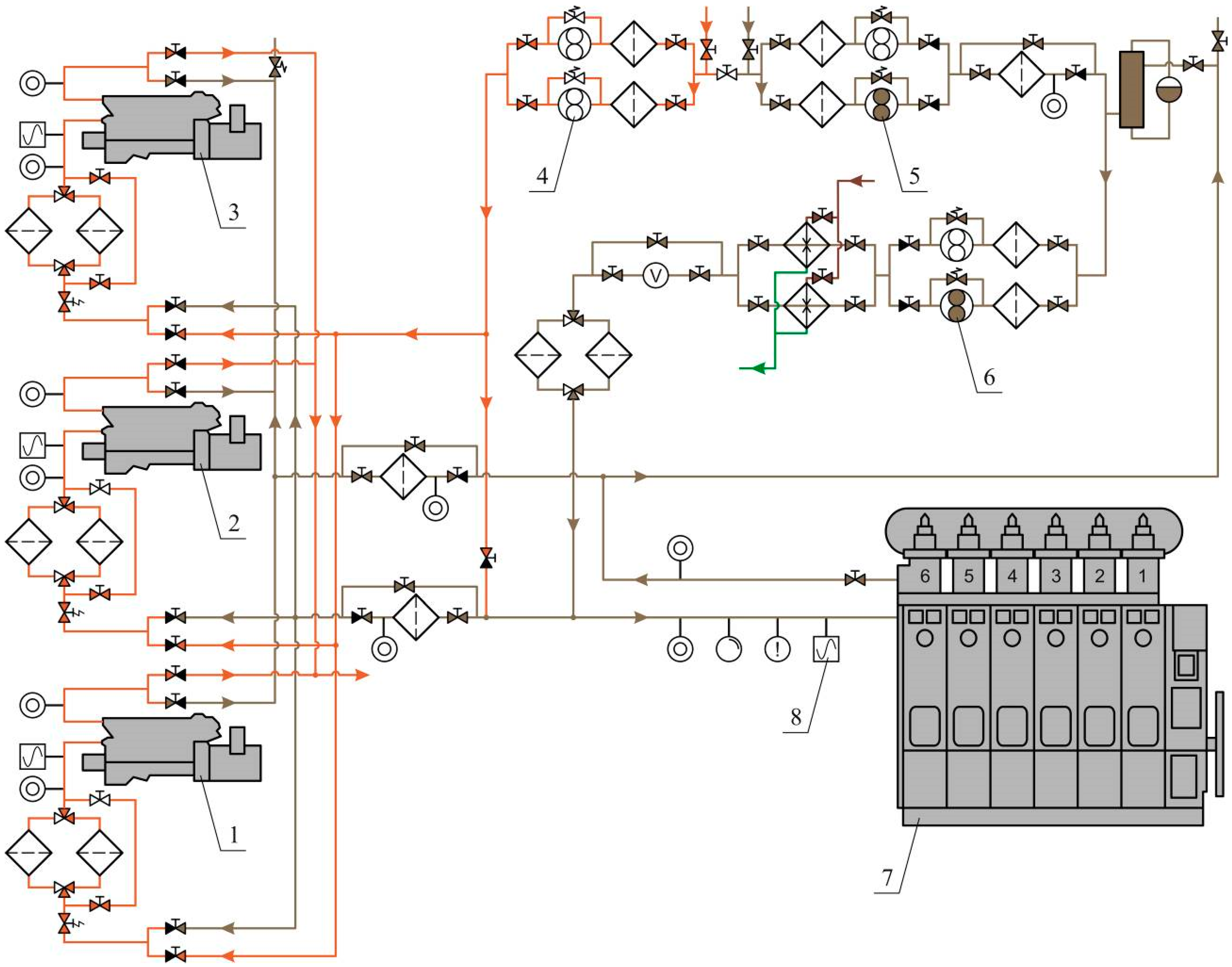
The PLS-QXDY3000W ultrasonic generator was installed in the fuel system loop directly before the high-pressure fuel equipment of the diesel engines. The fuel system diagram for the vessel’s YMD MAN-B&W 6S50ME-C9.7 and CMP MAN-B&W 5L23/30H diesel engines is shown in Figure 11.
The main engine YMD MAN-B&W 6S50ME-C9.7 (item 7 in Figure 11) and auxiliary diesel engines CMP MAN-B&W 5L23/30H (items 1, 2, 3 in Figure 11) operated on marine fuels RMG380 or DMA10. The flow of RMG380 fuel in the fuel system is marked in gray, while the flow of DMA10 fuel is marked in brown. The supply of RMG380 fuel was ensured by transfer pumps 5 and booster pumps 6. The supply of DMA10 fuel was carried out by transfer pumps 4.
To provide additional ultrasonic treatment of the fuel immediately before treatment with the high-pressure fuel equipment of each engine, an ultrasonic generator was installed (item 8 before the main engine (7) and similar ones before auxiliary engines 1, 2, 3). The purpose of the other equipment and measuring instruments is clear, as shown in Figure 8, and does not require additional explanation.
The research to determine the effect of ultrasonic fuel treatment on SOX emissions was carried out under conditions of different loads on the ship’s power plant according to the modes given in Table 6.
The operational modes of the main engine YMD MAN-BW 6S50ME-C9.7 and the auxiliary diesel engines CMP MAN-BW 5L23/30H were monitored using the ship’s diagnostic system ProPower. This included determining the rotational speed at the power of the diesels, as well as several key characteristics: compression end pressure, maximum combustion pressure, average indicator pressure, exhaust gas temperature, and specific fuel consumption [109,110,111].
All studies were conducted exclusively under constant load conditions, applied to both the main engine and auxiliary engines. Ultrasonic fuel treatment did not affect its cyclic supply.
The engine speed automatic control system maintained a constant specific fuel consumption (with an accuracy of ±0.5%), while the automatic fuel viscosity control system ensured stable viscosity (with an accuracy of ±0.5 cSt) and fuel temperature (with an accuracy of ±1 °C) before the high-pressure fuel injection equipment. Additionally, constant values were maintained for the fresh water in the engine cooling system and the oil temperature in both the circulating and cylinder lubrication systems.
The accuracy of the ultrasonic wave frequency was ensured by the technical specifications of the ultrasonic generator.
During the research, the vessel conducted navigational passage through Tallinn, Estonia—Rotterdam, Netherlands—Santa Cruz de Tenerife, Canary Islands, Spain (bunkering)—Conakry, Guinea—Casablanka, Morocco—Bergen, Norway. At the same time, the route passed both inside special ecological areas (The North Sea SECA and The Baltic Sea SECA) and outside of SECAs.
Under all operating modes and conditions of the vessel, the primary objective of the study was to determine the effect of supplementary ultrasonic fuel treatment on sulfur oxide emissions. The ultrasonic wave frequency was set using the PLS-QXDY3000W ultrasonic generator. Sulfur oxide emissions in the exhaust gases were continuously monitored automatically by the exhaust gas cleaning system (EGCS). The dataset comprising the dependence of sulfur oxide emissions on ultrasonic wave frequency across various operating modes of the ship’s power plant was systematically accumulated in an archival file.
The primary criterion for evaluating the effectiveness of exhaust gas cleaning when using supplementary ultrasonic fuel treatment was the change in carbon dioxide CO2 emissions, sulfur dioxide SO2 emissions, and their ratio SO2/CO2. These parameters were recorded across all experimental conditions, including varying ultrasonic frequencies and diesel engine loads.

4. Results

All experimental studies were conducted using certified measuring equipment integrated into the exhaust gas cleaning system; this was also installed on the marine diesel engines YMD MAN-B&W 6S50ME-C9.7 and CMP MAN-B&W 5L23/30H. During the research period, the diesel engines operated using RMG380 fuel.
The automatic fuel viscosity regulation system maintained this parameter within the range of 5.0–5.1 cSt for each diesel engine involved in the research. It ensured consistency in the intramolecular bonds of the fuel subjected to ultrasonic treatment, which was then delivered to the fuel injection system and subsequently combusted in the diesel engine cylinders. The reduction in fuel viscosity from 260–280 cSt (as stored in settling tanks) to 5.0–5.1 cSt (at which ultrasonic treatment was applied) contributed to the weakening of intermolecular bonds among the structural components of the fuel, including sulfur-containing compounds. This enhanced the influence of ultrasonic waves on the fuel’s structural framework and improved the efficiency of sulfur-containing component removal [43,80].
The continuity of the fuel flow entering the diesel engine cylinders and undergoing ultrasonic treatment was monitored using a flowmeter installed on the fuel supply line. The stability of the fuel flow rate, as recorded by the flowmeter, indicated steady flow conditions and the absence of “airlocks”. Additionally, the fuel pressure in the fuel rail was maintained at a constant level for each diesel engine, with deviations from the mean value not exceeding ±0.2%. Ensuring these conditions promoted uniform ultrasonic generator action on the structural components of the fuel across for each diesel engine [80,84].
The tests were performed exclusively under steady-state operating conditions of the marine diesel engines, which eliminated the influence of transient processes on the accuracy of the results [112,113,114]. Prior to data recording, the engines operated for 0.5–1 h at the selected load, which allowed the temperature, pressure and other working cycle parameters to be stabilized [115,116,117,118]. Furthermore, the temperature and pressure values in the lubrication and cooling systems of the diesel engines were also maintained at constant levels. This ensured thermal stability in the components of the cylinder assembly, air intake system, and exhaust gas system, while also preventing uncontrolled condensation of moisture from scavenge air and sulfur compounds from exhaust gases. The duration of each test was 2–3 h, ensuring consistent measurement of the monitored parameters [119,120,121,122]. The experimental database for each operating mode was collected over a 1.5 h period at 3 min intervals (according to the registration table presented in Figure 10). The EGCS software enabled determination of average parameter values for the corresponding research period. The research was conducted in two configurations: 1—using only scrubber cleaning of exhaust gases; 2—using scrubber cleaning of exhaust gases with simultaneous additional fuel treatment via the PLS-QXDY3000W ultrasonic generator. The studies were performed both when the vessel was within the SECA and outside of the SECA. The main parameters monitored during the studies were carbon dioxide CO2 emissions, sulfur dioxide SO2 emissions, and the SO2/CO2 ratio. The recording, processing, and systematization of all results were performed using the EGCS software, thereby eliminating human factor interference and preventing data collection errors.
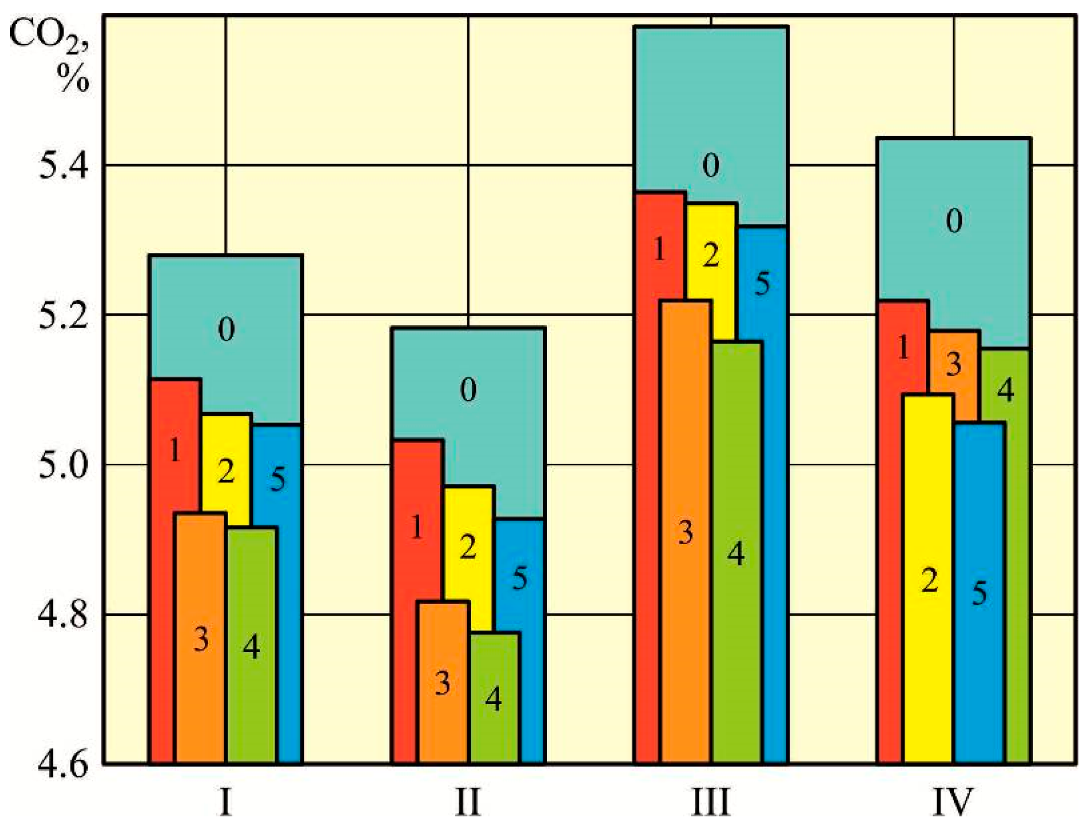
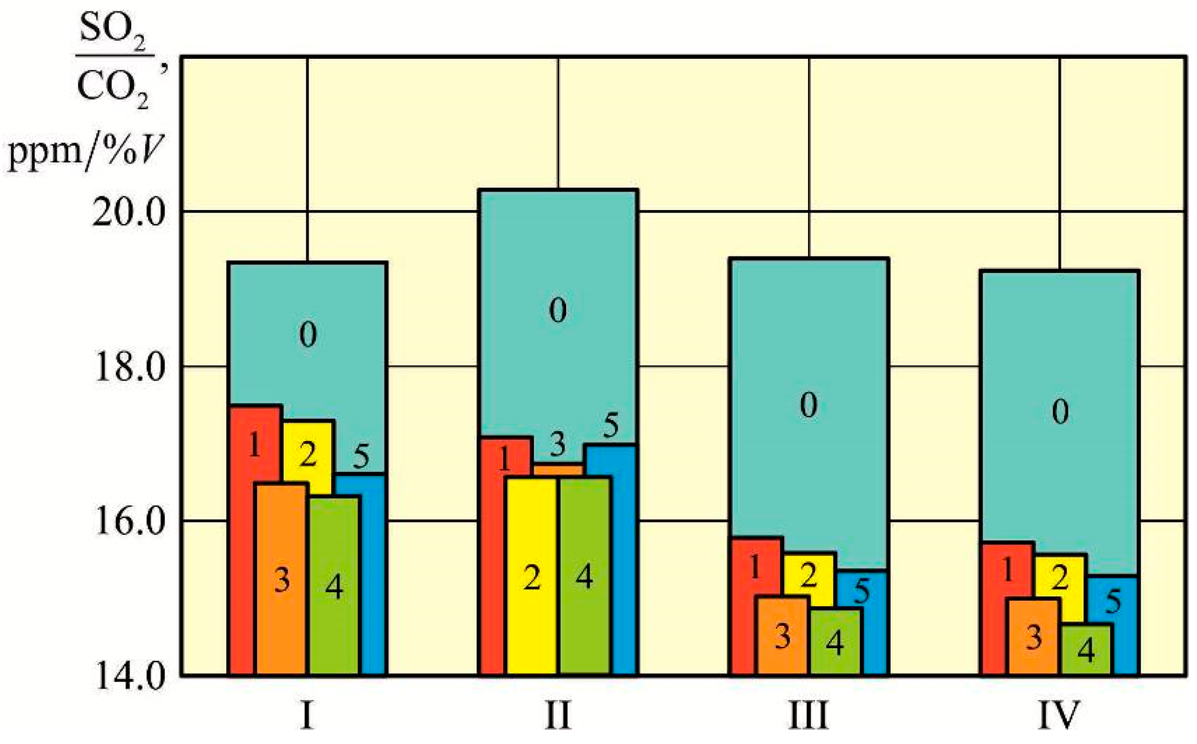
The frequency of ultrasonic waves used for ultrasonic fuel treatment (UFT) varied depending on experimental conditions and was set at 20 kHz, 25 kHz, 28 kHz, 33 kHz, and 40 kHz. The results of these studies are presented in Table 7, Table 8, Table 9, Table 10, Table 11 and Table 12. In addition, Table 7, Table 8, Table 9, Table 10, Table 11 and Table 12 show the results of tests performed while the vessel was inside and outside of the SECAs.
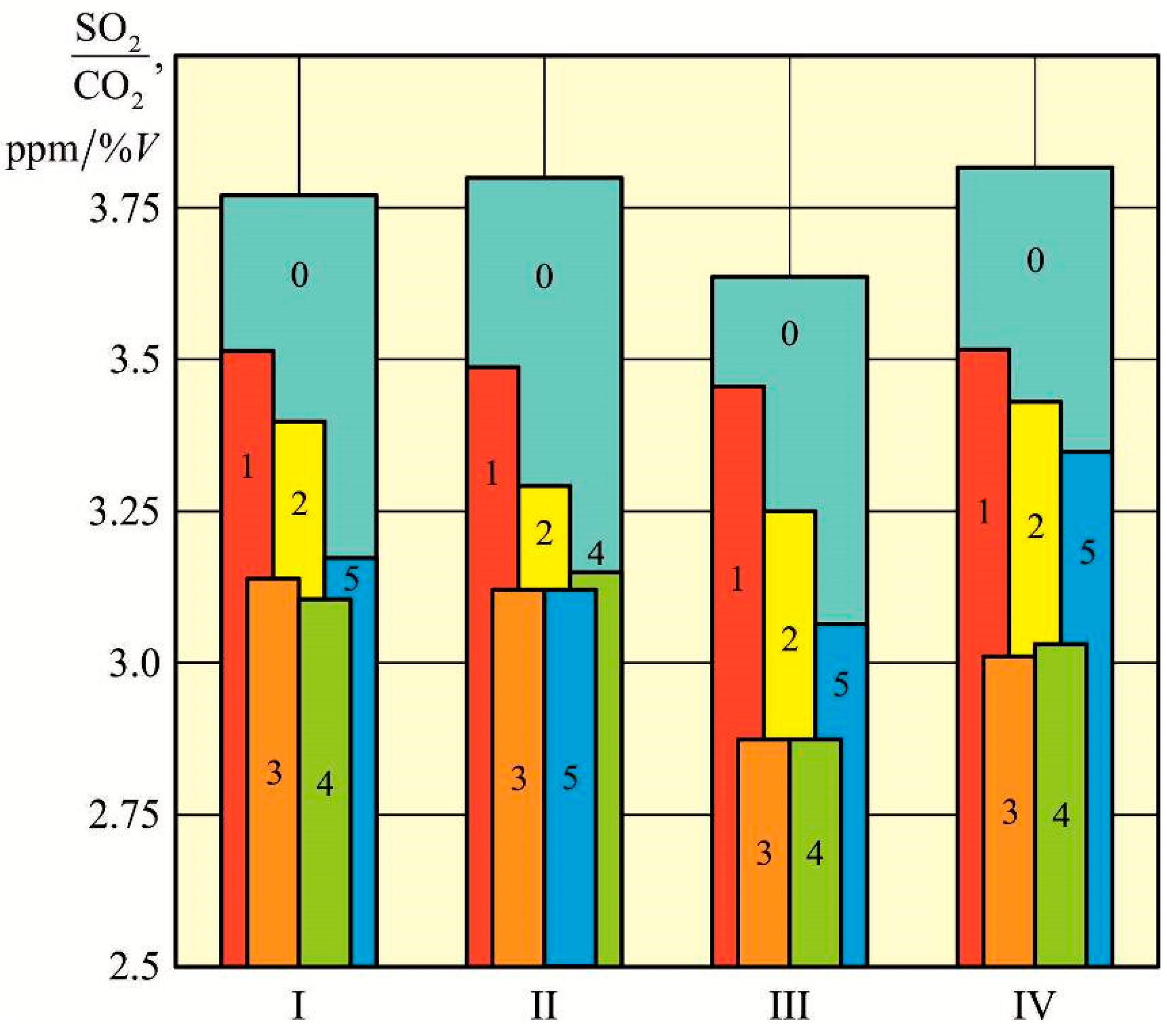
For better visualization, diagrams have been created based on the results presented in Table 7, Table 8 and Table 9Figure 12, Figure 13 and Figure 14.
For better visualization, diagrams have been created based on the results presented in Table 10, Table 11 and Table 12Figure 15, Figure 16 and Figure 17.
The improvement in the ship’s environmental performance and her power plant when using additional ultrasonic treatment of fuel can be determined by the relative reduction in harmful emissions:
Carbon dioxide ΔCO2
Δ CO 2 = CO 2 CO 2 UST CO 2 100 % ;
Sulfur dioxide ΔSO2
Δ SO 2 = SO 2 SO 2 UST SO 2 100 % ;
Ratio Δ(SO2/CO2)
Δ SO 2 / CO 2 = SO 2 / CO 2 SO 2 / CO 2 UST SO 2 / CO 2 100 % ;
where CO 2 ,   SO 2 ,   SO 2 / CO 2 show the emissions of carbon dioxide and sulfur dioxide, as well as their ratio for the corresponding operating mode of the exhaust gas cleaning system without the use of additional ultrasonic fuel treatment; CO 2 UST ,   SO 2 UST ,   SO 2 / CO 2 UST show the values of the same indicators during the use of additional ultrasonic fuel treatment.
Taking into account the numerical values provided in Table 7, Table 8, Table 9, Table 10, Table 11 and Table 12, the values obtained using Expressions (1)–(3) are presented in Table 13, Table 14, Table 15, Table 16, Table 17 and Table 18.
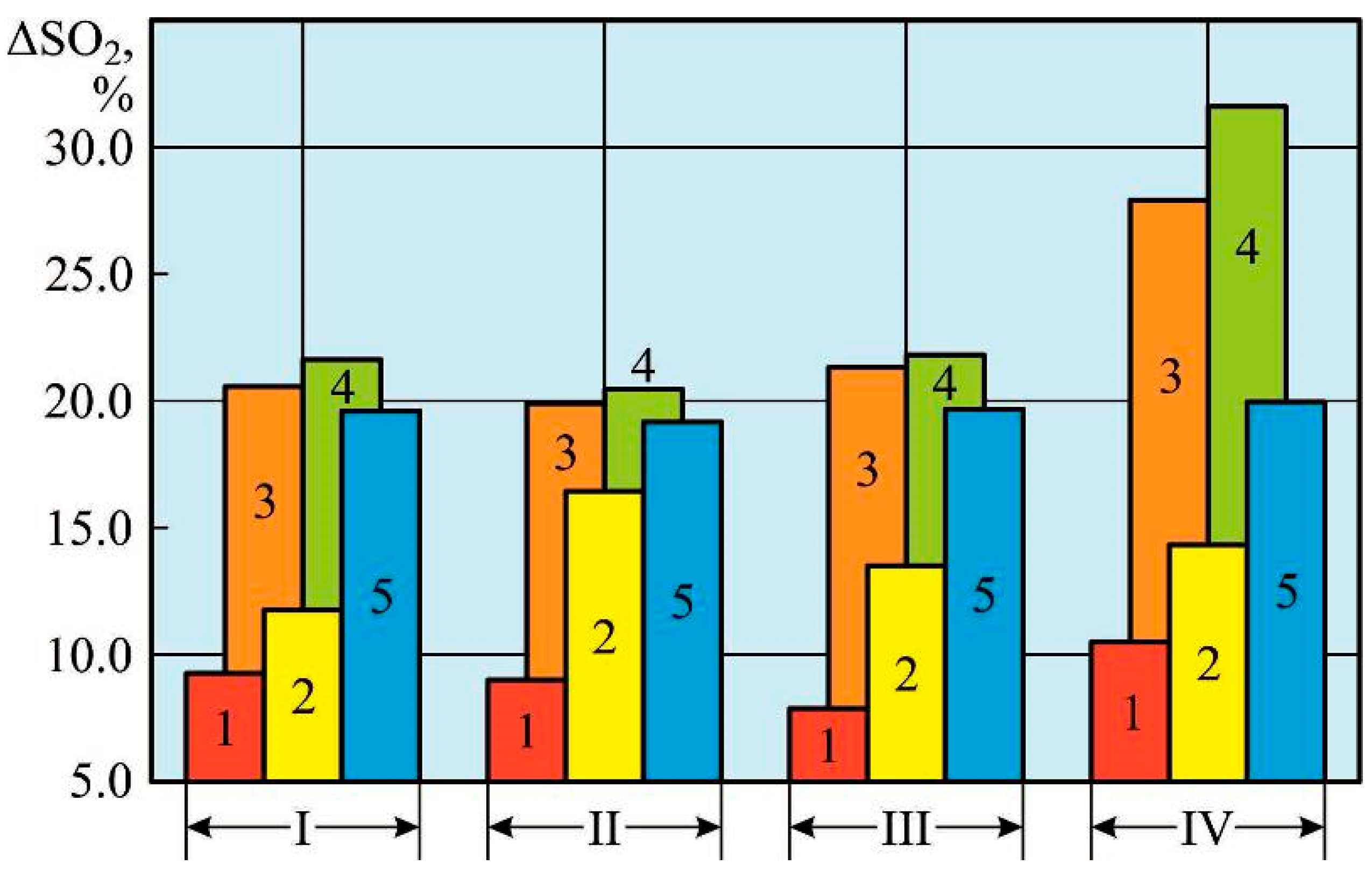
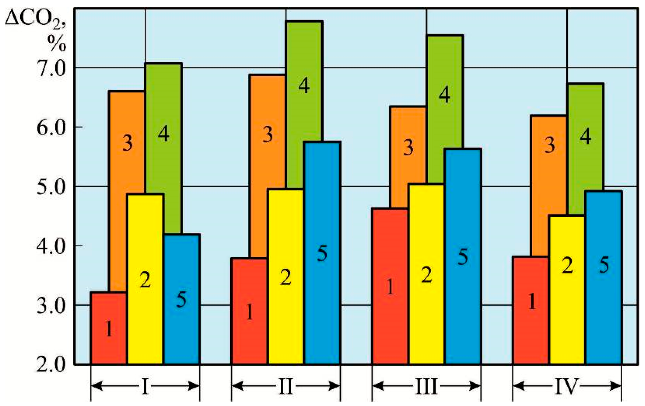
For better visualization, diagrams have been created based on the results presented in Table 13, Table 14 and Table 15Figure 18, Figure 19 and Figure 20.
For better visualization, diagrams have been created based on the results presented in Table 16, Table 17 and Table 18Figure 21, Figure 22 and Figure 23.
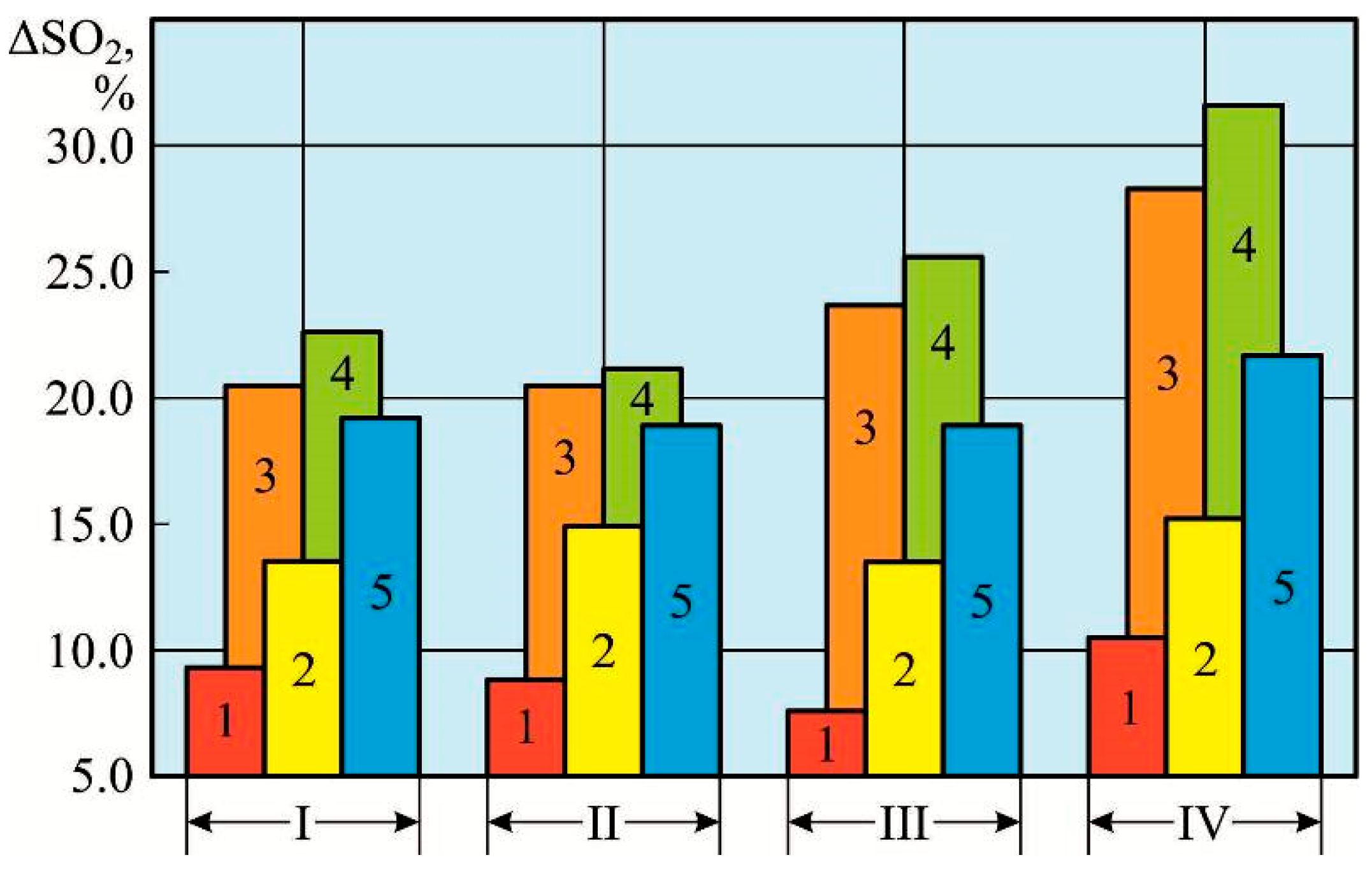
The research results presented in Table 13, Table 14, Table 15, Table 16, Table 17 and Table 18 and illustrated in Figure 18, Figure 19, Figure 20, Figure 21, Figure 22 and Figure 23 characterize the effectiveness of the integrated reduction in sulfur oxide emissions achieved through ultrasonic fuel treatment and scrubber exhaust gas cleaning. The results indicate that the dependencies of carbon dioxide (CO2) emissions, sulfur dioxide (SO2) emissions, and their ratio (SO2/CO2) on the frequency of ultrasonic waves are nonlinear. There is a specific frequency range of ultrasonic irradiation that provides minimal values of CO2 and SO2 emissions, as well as the ratio of SO2/CO2 in the exhaust gases. The proposed technology enables the experimental determination of optimal ultrasonic frequencies within this range. It is recommended to perform additional ultrasonic fuel treatment at these frequencies for fuels with elevated sulfur content.
All studies were conducted directly by the ship’s crew. The technology for conducting the research was agreed upon with the technical department of the company that manages the ship. All working conditions and experimental procedures complied with the requirements of the International Conventions MARPOL and the International Convention for the Safety of Life at Sea (SOLAS).
Similar studies were also conducted during other voyages of the vessel, as well as on sister ships belonging to the shipping company and equipped with analogous power plants and exhaust gas cleaning systems. In all cases, the sulfur content in the fuel exceeded 3%, ranging from 3.15 to 3.45% by mass. Ultrasonic irradiation of the fuel was performed within the considered frequency range. In all instances, the primary criterion for assessing the effectiveness of ultrasonic fuel treatment was the relative reduction in carbon dioxide emissions (ΔCO2), sulfur dioxide emissions (ΔSO2), and the relative decrease in the SO2/CO2 ratio Δ(SO2/CO2). Concurrently, the results obtained were consistent and directionally similar to those presented herein, confirming the versatility of the proposed technology and supporting its recommendation for marine fuels with diverse structural characteristics.

5. Discussion

Ensuring the environmental performance of ship power plants remains a primary task in the context of reducing harmful impacts on the environment. Particular attention is given to controlling sulfur oxide emissions, the level of which directly depends on the sulfur content in the fuel (which is limited to 0.5% by mass in most cases). At the same time, according to the requirements of Annex VI of MARPOL, the use of marine fuels with a sulfur content exceeding 0.5% is permitted when special exhaust gas cleaning systems (the most common of which are SOX scrubbers) are installed on the vessel. Under these conditions, it is possible to use fuel with a sulfur content of up to 3.5%. The cleaning system neutralizes harmful SOX emissions to a level equivalent to burning fuel with a sulfur content not exceeding 0.5% by mass.
An additional method for reducing SOX emissions is ultrasonic fuel treatment, which involves influencing the structural components of fuel (primarily sulfur-containing compounds) with waves of a specific frequency. The action of ultrasonic waves disrupts intermolecular bonds in petroleum-derived fuels, such as carbon–sulfur C–S, sulfur–sulfur S–S and carbon–hydrogen C–H, leading to the formation of hydrogen sulfide (H2S) in a gaseous state. The concentration of hydrogen sulfide remains well below permissible limits, thus posing no risk to the vessel’s crew or equipment. Moreover, the gaseous phase of hydrogen sulfide is removed from the fuel surface via the ship’s ventilation system.
An additional method for reducing SOX emissions is ultrasonic treatment of the fuel, which involves influencing the structural components of the fuel (primarily those containing sulfur) with waves of a specific frequency.
Supplementary fuel treatment by means of ultrasonic irradiation aimed at reducing sulfur oxide emissions from marine diesel exhaust gases represents an innovative solution. Traditionally, ultrasonic treatment has been considered only in terms of its changes in the structural and operational characteristics of fuels [64,84,123]. The points of sequential impact of ultrasonic fuel treatment on fuel desulfurization and the subsequent reduction in sulfur oxide emissions have scarcely been investigated. Likewise, exhaust gas cleaning via scrubber systems has predominantly been studied as a separate field of inquiry [39,42,72]. Furthermore, research on the integrated effects of ultrasonic fuel treatment combined with scrubber exhaust gas cleaning on the environmental performance of marine vessels is virtually nonexistent.
One method to enhance the environmental efficiency of marine diesel engines in general, and the fuel preparation system in particular, is fuel desulfurization, which can be achieved through supplementary ultrasonic treatment of the fuel. The application of ultrasound in shipboard fuel preparation systems has traditionally been limited to the creation of fuel blends and water-in-fuel emulsions. Isolated studies investigating the ultrasonic influence on the structural components of fuel have not determined the most optimal operating regimes of such equipment from the perspective of sulfur oxide emission reduction [43,123,124].
From the viewpoint of dispersion systems, marine diesel fuel does not obey Newton’s, Poiseuille’s, or Stokes’ laws, as its long, randomly arranged molecules form a flexible network. Ultrasonic waves disrupt this continuous fuel chain by breaking the bonds between individual molecules. Consequently, ultrasonic treatment influences the structural configuration of the fuel, specifically causing the rupture of Van der Waals’ interactions within the fuel matrix. Supplementary ultrasonic treatment enhances the dispersive qualities of the fuel and leads to additional activation of its hydrocarbon components, particularly the C–H bonds. Simultaneously, it is possible to operate ultrasonic generators under conditions where the energy of the ultrasonic waves is sufficient to excite, ionize, and dissociate sulfur molecules [80,125,126]. This process subsequently results in the cleavage of carbon–sulfur C–S bonds within the fuel structure. Thus, ultrasonic fuel treatment induces the breaking of molecular chains under increased load conditions and tensile stresses. An additional outcome of ultrasonic treatment is the formation of hydrogen–sulfur–hydrogen H–S–H bonds. The concentration range of the resulting hydrogen sulfide (H2S) remains below toxic levels and does not adversely affect the environmental performance of the ship’s exhaust gases.
The research findings confirm the effectiveness of supplementary ultrasonic fuel treatment as a method that contributes to the reduction in sulfur oxide emissions from exhaust gases. Thermochemical studies investigating the impact of ultrasonic irradiation on the structural characteristics of the fuel [52,53,54] corroborate a partial decrease in sulfur content within the fuel, accompanied by alterations in its intermolecular structure [78,80]. These changes occur through the fragmentation of long molecular chains into smaller components and the disruption of intramolecular bonds among sulfur-containing compounds. Consequently, a synergistic effect on sulfur oxide emissions from the exhaust gases is established. The reduction in sulfur oxide emissions is achieved through a dual mechanism: the activation of sulfur-bearing components in the fuel via additional ultrasonic treatment, and the direct purification of exhaust gases by the ship’s installed scrubber system. The former is effected through ultrasonic fuel treatment, while the latter is implemented by the onboard exhaust gas cleaning system.
The use of additional ultrasonic treatment of fuel significantly enhances the efficiency of scrubber systems for cleaning exhaust gases from ship diesel engines. This is reflected in the reduction in the following environmental indicators: the volume of carbon dioxide (CO2) emissions and sulfur dioxide (SO2) emissions, as well as their ratio (SO2/CO2), which determines the effectiveness of scrubber exhaust gas cleaning systems and is regulated by the requirements of Annex VI of MARPOL when they are used. The relevance of using additional ultrasonic treatment of fuel becomes especially important when the vessel is in SECAs, where stricter requirements for sulfur oxide emissions from exhaust gases are imposed.
As a result of the experimental studies, the optimal frequency of ultrasonic waves for the ultrasonic treatment of marine fuel RMG380 (one of the most common fuels with a sulfur content of up to 3.5%) was determined. The optimal frequency of ultrasonic waves is difficult to analytically correlate with the structural composition of the fuel, which (depending on the oil source and processing technology) varies in the content of its main components and is characterized by different intermolecular forces between them. This is precisely why the frequency and amplitude of ultrasonic waves affect different fuel grades differently. The optimal ultrasonic treatment regime for one fuel grade may be less effective for another. This is further supported by the nonlinear dependence of sulfur oxide emissions on the frequency of ultrasonic waves
Ultrasonic fuel treatment promotes the fragmentation of long organic chains of fuel structural components into shorter ones. This process involves the rupture of certain intermolecular bonds (in carbon–sulfur and carbon–hydrogen compounds) and the formation of new ones (hydrogen–sulfur). Ultimately, the ultrasound-assisted fuel desulfurization process results in the release of hydrogen sulfide (H2S) within the gas phase which is produced above the fuel surface. For fuel with an initial sulfur impurity content of up to 3.5%, the concentration of H2S in the gas phase does not exceed 0.04 mg/m3, which permits the integration of ultrasonic fuel treatment units into marine fuel preparation systems.
The ultrasonic waves generated during the fuel treatment by the ultrasonic generator have the most effective impact on the sulfur-containing components of the fuel. Ultimately, this leads to a reduction in SO2 emissions by 7.9% to 30.5%, depending on the initial sulfur content in the fuel and the operational mode of the ship’s diesel engines.
An important advantage of ultrasonic treatment is the preservation of the main operational characteristics of the fuel. Preliminary studies (the results of which are not included in the article) have confirmed that during additional ultrasonic treatment of the fuel, its viscosity, density, and temperature remain unchanged, ensuring stability in cyclic supply and the absence of additional hydraulic losses in the system. Moreover, monitoring of the operating cycle parameters of the diesel engines (end-of-compression pressure, maximum combustion pressure, exhaust gas temperature) has confirmed their alignment with similar indicators when operating ship diesel engines without additional ultrasonic fuel treatment.
The limitations of ultrasonic technologies include their lower efficiency (compared to the impact on sulfur oxide emissions reduction) in the removal of other pollutants from exhaust gases, such as nitrogen oxides (NOX) and particulate matter (PM). Ultrasonic treatment is effective only for the removal of fuel-bound NOX. However, the nitrogen content in marine fuels does not exceed 0.3–0.5%. Moreover, nitrogen exhibits stronger intermolecular bonds with other structural components of the fuel (compared to sulfur). Both factors contribute to the reduced efficiency of nitrogen removal from the fuel by ultrasonic treatment. The removal of atmospheric NOX and particulate matter PM from exhaust gases is of low efficiency because of the large cross-sectional area of the exhaust duct and the high velocity of the exhaust gases.
The main limitations associated with the use of additional ultrasonic fuel treatment stem from the need to install, calibrate, and determine the optimal operating modes of the equipment that facilitates this process. Further research to determine the optimal ultrasonic frequency needs to be conducted for each type of fuel taken on board the vessel. At the same time, recommendations developed for specific types of fuel and individual ship diesel engines can be implemented when using similar types of fuel in fuel systems and for exhaust gas cleaning systems of other diesel engines.
The application of ultrasound represents an advanced technology employed across diverse industrial sectors, including metallurgy [127,128], construction [129,130], as well as in geology [131] and medicine [132]. This underscores its broad applicability and versatility.

6. Conclusions

Research conducted on the ship diesel engines YMD MAN-BW 6S50ME-C9.7 and CMP MAN-BW 5L23/30H of a Bulk Carrier with a deadweight of 64,710 tons has determined the optimal conditions for the use of additional ultrasonic fuel treatment and allows us to conclude the following:
1. The most effective location for conducting ultrasonic treatment is in the fuel system just before the high-pressure fuel equipment of the diesel engine. Installing a special ultrasonic generator ensures a uniform impact of ultrasonic waves on the fuel.
2. Additional ultrasonic fuel treatment technology contributes to improving the environmental performance of ship diesel engines. The combined use of a scrubber system for exhaust gas cleaning and ultrasonic fuel treatment (compared to scrubber-only exhaust gas cleaning) results in a reduction in carbon dioxide (CO2) and sulfur dioxide (SO2) emissions, as well as their ratio (SO2/CO2). The additional ultrasonic fuel treatment has the most significant effect on sulfur-containing components, leading to a substantial decrease in SO2 emissions from exhaust gases. For various operating conditions of the YMD MAN-BW 6S50ME-C9.7 and CMP MAN-BW 5L23/30H ship diesel engines, the following range of reductions in CO2 emission was established:
  • 2.9–5.8% during operation inside SECAs;
  • 2.9–7.5% during operation outside SECAs;
The following range of reductions in SO2 emission was also established:
  • 9.3–33.1% during operation inside SECAs;
  • 9.8–23.8% during operation outside SECAs.
This provides us with the following range of reductions in the SO2/CO2 ratio, which is crucial for assessing the effectiveness of the scrubber system for exhaust gas cleaning and is regulated by the requirements of Annex VI of MARPOL:
  • 6.3–21.5% during operation inside SECAs;
  • 9.3–23.7% during operation outside SECAs.
3. The dependencies of carbon dioxide and sulfur dioxide emissions on the frequency of ultrasonic fuel treatment are not linear. To achieve the greatest efficiency in reducing CO2 and SO2 emissions, ultrasonic fuel treatment must be performed at an optimal frequency of ultrasonic waves. During the research, it was found that among the frequency range of ultrasonic waves (20 kHz, 25 kHz, 28 kHz, 33 kHz, 40 kHz) used for additional fuel treatment, the greatest reduction in CO2 and SO2 emissions is achieved at frequencies of 28 kHz and 33 kHz. These values are recognized as optimal for performing additional fuel treatment when used in conjunction with scrubber exhaust gas cleaning. Due to the complexity of the chemical and thermodynamic processes occurring during ultrasonic fuel treatment and exhaust gas purification, the determination of the optimal frequency of ultrasonic waves is advisable to be carried out experimentally.
It is important to emphasize the greater effectiveness of using additional ultrasonic treatment technology while vessels are located within SECAs, i.e., in coastal waters. These marine areas are subjected to the most significant negative impact from transportation means, and they have the most stringent environmental requirements and regulations.
4. An important advantage of ultrasonic treatment technology is its versatility. This method can be applied to any type of liquid marine fuel regardless of its fractional composition and physicochemical characteristics (viscosity, density, flash point). This makes ultrasonic treatment technology accessible for widespread implementation without the need for modifications to existing fuel systems.
5. The combination of scrubber systems for cleaning exhaust gases from ship diesel engines from sulfur oxides SOX and ultrasonic fuel treatment technology before injection into the engine cylinder contributes to reducing SOX emissions and thus enhances the ecological sustainability of marine vessel power plants.
Author Contributions

Conceptualization, S.S.; methodology, S.S., V.C. and O.K.; validation, D.R., O.K., V.M. and S.K.; data curation, O.K., D.R. and S.K.; writing, original draft preparation, O.K., V.M. and D.R.; writing, review and editing, S.S., S.K. and V.C.; visualization, S.S., V.C. and O.K.; investigation, S.S., D.R., V.M. and O.K. All authors have read and agreed to the published version of the manuscript.

Funding

This research received no external funding.

Institutional Review Board Statement

Not applicable.

Informed Consent Statement

Not applicable.

Data Availability Statement

The original contributions presented in this study are included in the article. Further inquiries can be directed to the corresponding author.

Conflicts of Interest

The authors declare no conflicts of interest.

Abbreviations

EGCSExhaust Gas Cleaning System
HFOHeavy Fuel Oil
ICEInternal combustion engine
MDOMarine Diesel Oil
MGOMarine Gas Oil
SECAsSulfur Emission Control Areas
SOLASInternational Convention for the Safety of Life at Sea
UFTUltrasonic fuel treatment

References

  1. Kučera, O.; Píštěk, V.; Fomin, O.; Kučera, P.; Sagin, S. Measuring Device for More Precise Mistuning Identification of Integrated Bladed Discs. Symmetry 2025, 17, 717. [Google Scholar] [CrossRef]
  2. Fomin, O.; Lovska, A.; Kučera, P.; Píštěk, V. Substantiation of Improvements for the Bearing Structure of an Open Car to Provide a Higher Security during Rail/Sea Transportation. J. Mar. Sci. Eng. 2021, 9, 873. [Google Scholar] [CrossRef]
  3. Vladov, S.; Shmelov, Y.; Yakovliev, R. Optimization of Helicopters Aircraft Engine Working Process Using Neural Networks Technologies. CEUR Workshop Proc. 2022, 3171, 1639–1656. Available online: https://ceur-ws.org/Vol-3171/paper117.pdf (accessed on 23 May 2025).
  4. Holovan, A.; Gritsuk, I.; Verbovskyi, V.; Kalchenko, V.; Grytsuk, Y.; Verbovskiy, O.; Dotsenko, S.; Lysykh, A.; Symonenko, R.; Subochev, O. Algorithmic support and efficiency analysis of comprehensive prescriptive maintenance for cargo ships using predictive monitoring. East.-Eur. J. Enterp. Technol. 2025, 135, 13. [Google Scholar] [CrossRef]
  5. Sagin, S.V.; Karianskyi, S.; Sagin, S.S.; Volkov, O.; Zablotskyi, Y.; Fomin, O.; Píštěk, V.; Kučera, P. Ensuring the safety of maritime transportation of drilling fluids by platform supply-class vessel. Appl. Ocean Res. 2023, 140, 103745. [Google Scholar] [CrossRef]
  6. Budashko, V.; Sandler, A.; Khniunin, S.; Bogach, V. Design of the predictive management and control system for combined propulsion complex. East.-Eur. J. Ent. Technol. 2024, 131, 90. [Google Scholar] [CrossRef]
  7. Wen, M.; Li, Y.; Zhu, W.; Cao, R.; Sun, K. Experimental Study on Effects of RCSL and RCTL Combustion Chamber for Combustion Process of Highly Intensified Diesel Engine. Energies 2022, 15, 6368. [Google Scholar] [CrossRef]
  8. Varbanets, R.; Fomin, O.; Píštěk, V.; Klymenko, V.; Minchev, D.; Khrulev, A.; Zalozh, V.; Kučera, P. Acoustic Method for Estimation of Marine Low-Speed Engine Turbocharger Parameters. J. Mar. Sci. Eng. 2021, 9, 321. [Google Scholar] [CrossRef]
  9. Nelyubov, D.V.; Fakhrutdinov, M.I.; Sarkisyan, A.A.; Sharin, E.A.; Ershov, M.A.; Makhova, U.A.; Makhmudova, A.E.; Klimov, N.A.; Rogova, M.Y.; Savelenko, V.D.; et al. New Prospects of Waste Involvement in Marine Fuel Oil: Evolution of Composition and Requirements for Fuel with Sulfur Content up to 0.5%. J. Mar. Sci. Eng. 2023, 11, 1460. [Google Scholar] [CrossRef]
  10. Salova, T.; Lekomtsev, P.; Likhanov, V.; Lopatin, O.; Belov, E. Development of calculation methods and optimization of working processes of heat engines. AIP Conf. Proc. 2023, 2700, 050015. [Google Scholar] [CrossRef]
  11. Zablotsky, Y.V.; Sagin, S.V. Enhancing Fuel Efficiency and Environmental Specifications of a Marine Diesel When using Fuel Additives. Indian J. Sci. Technol. 2016, 9, 353–362. [Google Scholar] [CrossRef]
  12. Sagin, S.V.; Semenov, O.V. Motor Oil Viscosity Stratification in Friction Units of Marine Diesel Motors. Am. J. Appl. Sci. 2016, 13, 200–208. [Google Scholar] [CrossRef]
  13. Budashko, V.; Sandler, A.; Glazeva, O. Improvement of the Predictive Control Method for the High-Level Controller. In Proceedings of the EEE 17th International Conference on Advanced Trends in Radioelectronics, Telecommunications and Computer Engineering, Lviv, Ukraine, 8–12 October 2024; pp. 294–297. [Google Scholar] [CrossRef]
  14. Gorb, S.; Levinskyi, M.; Budurov, M. Sensitivity Optimisation of a Main Marine Diesel Engine Electronic Speed Governor. Sci. Horiz. 2021, 24, 9–19. [Google Scholar] [CrossRef]
  15. Zablotsky, Y.V.; Sagin, S.V. Maintaining Boundary and Hydrodynamic Lubrication Modes in Operating High-pressure Fuel Injection Pumps of Marine Diesel Engines. Indian J. Sci. Technol. 2016, 9, 208–216. [Google Scholar] [CrossRef]
  16. Budashko, V.; Shevchenko, V. Solving a task of coordinated control over a ship automated electric power system under a changing load. East.-Eur. J. Enterp. Technol. 2021, 2, 54–70. [Google Scholar] [CrossRef]
  17. Melnyk, O.; Onyshchenko, S.; Onishchenko, O.; Koskina, Y.; Lohinov, O.; Veretennik, O.; Stukalenko, O. Fundamental Concepts of Deck Cargo Handling and Transportation Safety. Eur. Transp. 2024, 98, 1. [Google Scholar] [CrossRef]
  18. Likhanov, V.A.; Lopatin, O.P. Dynamics of soot formation and burnout in a gas diesel cylinder. IOP Conf. Ser. Mater. Sci. Eng. 2020, 862, 062033. [Google Scholar] [CrossRef]
  19. Emblemsvåg, J. A Study on the Limitations of Green Alternative Fuels in Global Shipping in the Foreseeable Future. J. Mar. Sci. Eng. 2025, 13, 79. [Google Scholar] [CrossRef]
  20. Lopatin, O.P. Modeling of physico-chemical processes in the combustion chamber of gas diesel. AIP Conf. Proc. 2024, 2969, 050008. [Google Scholar] [CrossRef]
  21. Sagin, S.V.; Semenov, O.V. Marine Slow-Speed Diesel Engine Diagnosis with View to Cylinder Oil Specification. Am. J. Appl. Sci. 2016, 13, 618–627. [Google Scholar] [CrossRef]
  22. Kuzmin, K.A.; Sultanbekov, R.R.; Khromova, S.M.; Vovk, M.A.; Rudko, V.A. Establishing the influence of recycled used oil on the sedimentation stability of residual marine fuel. Fuel 2025, 389, 134625. [Google Scholar] [CrossRef]
  23. Sagin, S.; Sagin, A.; Zablotskyi, Y.; Fomin, O.; Píštěk, V.; Kučera, P. Method for Maintaining Technical Condition of Marine Diesel Engine Bearings. Lubricants 2025, 13, 146. [Google Scholar] [CrossRef]
  24. Ershov, M.A.; Savelenko, V.D.; Makhova, U.A.; Kapustin, V.M.; Abdellatief, T.M.M.; Karpov, N.V.; Dutlov, E.V.; Borisanov, D.V. Perspective towards a gasoline-property-first approach exhibiting octane hyperboosting based on isoolefinic hydrocarbons. Fuel 2022, 321, 124016. [Google Scholar] [CrossRef]
  25. Li, Z.; Yu, X.; Shang, J.; Chen, K.; Xin, X.; Zhang, W.; Yu, S. Container Liner Shipping System Design Considering Methanol-Powered Vessels. J. Mar. Sci. Eng. 2025, 13, 709. [Google Scholar] [CrossRef]
  26. Yilmaz, N.; Vigil, F.M.; Atmanli, A.; Donaldson, B. Detailed Analysis of PAH Formation, Toxicity and Regulated Pollutants in a Diesel Engine Running on Diesel Blends with n-Propanol, n-Butanol and n-Pentanol. Energies 2022, 15, 6487. [Google Scholar] [CrossRef]
  27. Stratiev, D.; Shishkova, I.; Argirov, G.; Dinkov, R.; Ivanov, M.; Sotirov, S.; Sotirova, E.; Bureva, V.; Nenov, S.; Atanassov, K.; et al. Roles of Catalysts and Feedstock in Optimizing the Performance of Heavy Fraction Conversion Processes: Fluid Catalytic Cracking and Ebullated Bed Vacuum Residue Hydrocracking. Catalysts 2024, 14, 616. [Google Scholar] [CrossRef]
  28. Sagin, S.; Kuropyatnyk, O.; Matieiko, O.; Razinkin, R.; Stoliaryk, T.; Volkov, O. Ensuring Operational Performance and Environmental Sustainability of Marine Diesel Engines through the Use of Biodiesel Fuel. J. Mar. Sci. Eng. 2024, 12, 1440. [Google Scholar] [CrossRef]
  29. Zhang, N.; Wang, X.; Wang, C.; Peng, Z.; Chen, Y.; Liu, L.; Chen, L.; Hu, J.; Wei, W.; Li, X. Design and Innovative Application of Ship CCUS Technology Under the Requirements of Green Shipping. J. Mar. Sci. Eng. 2025, 13, 1157. [Google Scholar] [CrossRef]
  30. ISO 8217:2024; Products from Petroleum, Synthetic and Renewable Sources–Fuels (Class F)–Specifications of Marine Fuels. ISO: Geneva, Switzerland, 2024. Available online: https://www.iso.org/standard/80579.html (accessed on 23 May 2025).
  31. Melnyk, O.; Onyshchenko, S.; Onishchenko, O.; Lohinov, O.; Ocheretna, V. Integral Approach to Vulnerability Assessment of Ship’s Critical Equipment and Systems. Trans. Marit. Sci. 2023, 12, 1–10. [Google Scholar] [CrossRef]
  32. Povarov, V.G.; Efimov, I.; Smyshlyaeva, K.I.; Rudko, V.A. Application of the UNIFAC Model for the Low-Sulfur Residue Marine Fuel Asphaltenes Solubility Calculation. J. Mar. Sci. Eng. 2022, 10, 1017. [Google Scholar] [CrossRef]
  33. Sagin, S.V.; Kuropyatnyk, O.A. The Use of Exhaust Gas Recirculation for Ensuring the Environmental Performance of Marine Diesel Engines. Naše More Int. J. Marit. Sci. Technol. 2018, 65, 78–86. [Google Scholar] [CrossRef]
  34. Kong, K.-J.; Hwang, S.-C. Development and Performance Evaluation Experiment of a Device for Simultaneous Reduction of SOx and PM. Energies 2024, 17, 3337. [Google Scholar] [CrossRef]
  35. Kuropyatnyk, O.A.; Sagin, S.V. The Exhaust Gas Recirculation as a Major Technique Designed to Reduce NOx Emissions from Marine Diesel Engines. Naše More Int. J. Marit. Sci. Technol. 2019, 66, 1–9. [Google Scholar] [CrossRef]
  36. Sagin, S.V.; Kuropyatnyk, O.A.; Zablotskyi, Y.V.; Gaichenia, O.V. Supplying of Marine Diesel Engine Ecological Parameters. Naše More Int. J. Marit. Sci. Technol. 2022, 69, 53–61. [Google Scholar] [CrossRef]
  37. Melnyk, O.; Onyshchenko, S.; Onishchenko, O. Development measures to enhance the ecological safety of ships and reduce operational pollution to the environment. Sci. J. Silesian Univ. Technol. Ser. Transp. 2023, 118, 195–206. [Google Scholar] [CrossRef]
  38. International Convention for the Prevention of Pollution from Ships (MARPOL). International Maritime Organization. Available online: https://www.imo.org/en/about/Conventions/Pages/International-Convention-for-the-Prevention-of-Pollution-from-Ships-(MARPOL).aspx (accessed on 14 February 2025).
  39. Zannis, T.C.; Katsanis, J.S.; Christopoulos, G.P.; Yfantis, E.A.; Papagiannakis, R.G.; Pariotis, E.G.; Rakopoulos, D.C.; Rakopoulos, C.D.; Vallis, A.G. Marine Exhaust Gas Treatment Systems for Compliance with the IMO 2020 Global Sulfur Cap and Tier III NOx Limits: A Review. Energies 2022, 15, 3638. [Google Scholar] [CrossRef]
  40. Lee, J.-U.; Hwang, S.-C.; Han, S.-H. Numerical and Experimental Study on NOx Reduction According to the Load in the SCR System of a Marine Boiler. J. Mar. Sci. Eng. 2023, 11, 777. [Google Scholar] [CrossRef]
  41. Guët, A.T.; Monios, J.; Cariou, P. Successful adoption of maritime environmental policy: The Mediterranean emission control area. Mar. Policy. 2024, 166, 106228. [Google Scholar] [CrossRef]
  42. Qi, J.; Feng, R.; Wang, S. Optimization of Fleet Scrubber Installation and Utilization Considering Sulfur Emission Control Areas and Marine Fuel Switching. J. Mar. Sci. Eng. 2023, 11, 1849. [Google Scholar] [CrossRef]
  43. Jee, J. Hybrid Multi-Criteria Decision-Making for Marine SOx Scrubber Systems. J. Mar. Sci. Eng. 2022, 10, 1599. [Google Scholar] [CrossRef]
  44. Available online: https://shipandbunker.com (accessed on 5 April 2025).
  45. Wen, Q.; Chen, X.; Peng, X.; Qiu, Y.; Wu, K.; Lin, Y.; Liang, P.; Xu, D. Integrated Environmental–Economic Assessment of Small-Scale Natural Gas Sweetening Processes. Processes 2025, 13, 2473. [Google Scholar] [CrossRef]
  46. Wang, C.; Lyu, Q. New Approach to the Combined Removal of NOx and SO2 for Circulating Fluidized Beds. ChemEngineering 2025, 9, 67. [Google Scholar] [CrossRef]
  47. Wang, S.; Wu, J.; Wu, Y.; Dong, W. Study on Separation of Desulfurization Wastewater in Ship Exhaust Gas Cleaning System with Rotating Dynamic Filtration. Membranes 2025, 15, 214. [Google Scholar] [CrossRef] [PubMed]
  48. Zhang, X.; Wang, R. Phase-Transfer Catalysis for Fuel Desulfurization. Catalysts 2025, 15, 724. [Google Scholar] [CrossRef]
  49. Chen, M.; Huang, T.; Tong, S.; Wang, C.; Zhang, M. Heteropolyacid-Based Poly(IonicLiquid) Catalyst for Ultra-Deep and Recyclable Oxidative Desulfurization of Fuels. Catalysts 2025, 15, 622. [Google Scholar] [CrossRef]
  50. Shao, C.; Gao, Y.; Qi, X.; Yang, X. Study on the Surface Structure of Nano-ZnO Desulfurizers and Their Performance and Mechanism in H2S Removal at Room Temperature. Catalysts 2025, 15, 547. [Google Scholar] [CrossRef]
  51. Wang, C.; Ding, J.; Wu, H.; Zhang, J.; Xu, J.; Zhang, Y.; Ma, M.; Zhang, M.; Li, H. The Facile Construction of Defect-Engineered and Surface-Modified UiO-66 MOFs for Promising Oxidative Desulfurization Performance. Nanomaterials 2025, 15, 931. [Google Scholar] [CrossRef]
  52. Pasawan, M.; Chen, S.-S.; Das, B.; Chang, H.-M.; Chang, C.-T.; Nguyen, T.X.Q.; Ku, H.-M.; Chen, Y.-F. Ultrasonication Assisted Catalytic Transesterification of Ceiba Pentandra (Kapok) Oil Derived Biodiesel Using Immobilized Iron Nanoparticles. Fuels 2022, 3, 113–131. [Google Scholar] [CrossRef]
  53. Iliev, I.; Filimonova, A.; Chichirov, A.; Vlasova, A.; Kamalieva, R.; Beloev, I. Natural and Waste Materials for Desulfurization of Gaseous Fuels and Petroleum Products. Fuels 2025, 6, 13. [Google Scholar] [CrossRef]
  54. Sagin, S.V.; Solodovnikov, V.G. Cavitation Treatment of High-Viscosity Marine Fuels for Medium-Speed Diesel Engines. Mod. Appl. Sci. 2015, 9, 269–278. [Google Scholar] [CrossRef]
  55. Popovskii, Y.M.; Sagin, S.V.; Khanmamedov, S.A.; Grebenyuk, M.N.; Teregerya, V.V. Designing, calculation, testing and reliability of machines: Influence of anisotropic fluids on the operation of frictional components. Russ. Eng. Res. 1996, 16, 1–7. [Google Scholar]
  56. Budashko, V.; Sandler, A.; Shevchenko, V. Diagnosis of the Technical Condition of High-tech Complexes by Probabilistic Methods. Int. J. Mar. Navig. Saf. Sea Transp. (TransNav) 2022, 16, 105–111. [Google Scholar] [CrossRef]
  57. Fu, Q.; Tian, J.; Liu, Y.; Qi, Z.; Jiao, H.; Yang, S. Comparison of the Reaction Characteristics of Different Fuels in the Supercritical Multicomponent Thermal Fluid Generation Process. Energies 2024, 17, 5376. [Google Scholar] [CrossRef]
  58. Fratita, M.; Chivu, R.-M.; Rusu, E.; Carp, G.B.; Ion, I.; Brito, F.P. Experimental Investigation of Methyl Ester–Ethanol Blends as a Sustainable Biofuel Alternative for Heavy Duty Engines. Sustainability 2025, 17, 253. [Google Scholar] [CrossRef]
  59. Zhang, Z.; Zheng, W.; Li, Y.; Cao, K.; Xie, M.; Wu, P. Monitoring Sulfur Content in Marine Fuel Oil Using Ultraviolet Imaging Technology. Atmosphere 2021, 12, 1182. [Google Scholar] [CrossRef]
  60. deManuel-López, F.; Díaz-Gutiérrez, D.; Camarero-Orive, A.; Parra-Santiago, J.I. Iberian Ports as a Funnel for Regulations on the Decarbonization of Maritime Transport. Sustainability 2024, 16, 862. [Google Scholar] [CrossRef]
  61. Zhou, D.; Wei, H.; Tan, Z.; Xue, S.; Qiu, Y.; Wu, S. Biodiesel as Dispersant to Improve the Stability of Asphaltene in Marine Very-Low-Sulfur Fuel Oil. J. Mar. Sci. Eng. 2023, 11, 315. [Google Scholar] [CrossRef]
  62. Yu, P.; Yin, Y.; Yue, Q.; Wu, S. Experimental Study of Ship Motion Effect on Pressurization and Holding Time of Tank Containers during Marine Transportation. Sustainability 2022, 14, 3595. [Google Scholar] [CrossRef]
  63. Ershov, M.A.; Savelenko, V.D.; Shvedova, N.S.; Kapustin, V.M.; Abdellatief, T.M.M.; Karpov, N.V.; Dutlov, E.V.; Borisanov, D.V. An evolving research agenda of merit function calculations for new gasoline compositions. Fuel 2022, 322, 124209. [Google Scholar] [CrossRef]
  64. Ju, H.-j.; Jeon, S.-k. Effect of Ultrasound Irradiation on the Properties Sulfur Contents of Blended Very Low-Sulfur Fuel Oil (VLSFO). J. Mar. Sci. Eng. 2022, 10, 980. [Google Scholar] [CrossRef]
  65. Sagin, S.; Sagin, A. Development of method for managing risk factors for emergency situations when using low-sulfur content fuel in marine diesel engines. Technol. Audit. Prod. Reserves 2023, 5, 37–43. [Google Scholar] [CrossRef]
  66. Grzelakowski, A.S.; Herdzik, J.; Skiba, S. Maritime Shipping Decarbonization: Roadmap to Meet Zero-Emission Target in Shipping as a Link in the Global Supply Chains. Energies 2022, 15, 6150. [Google Scholar] [CrossRef]
  67. Sagin, S.; Haichenia, O.; Karianskyi, S.; Kuropyatnyk, O.; Razinkin, R.; Sagin, A.; Volkov, O. Improving Green Shipping by Using Alternative Fuels in Ship Diesel Engines. J. Mar. Sci. Eng. 2025, 13, 589. [Google Scholar] [CrossRef]
  68. Amoresano, A.; Langella, G.; Iodice, P.; Roscioli, S. Numerical Analysis of SO2 Absorption inside a Single Water Drop. Atmosphere 2023, 14, 1746. [Google Scholar] [CrossRef]
  69. Lee, T.-H.; Kang, I.-S. Small Combustion Chamber for Marine Fuel Oil and Analysis of Exhaust Gas Characteristics of Marine Gas Oil. J. Mar. Sci. Eng. 2023, 11, 609. [Google Scholar] [CrossRef]
  70. Study of Exhaust Gas Cleaning Systems for Vessels to Fulfill IMO III in 2016. Available online: https://www.researchgate.net/publication/277244191_Study_of_exhaust_gas_cleaning_systems_for_vessels_to_fulfill_IMO_III_in_2016 (accessed on 23 May 2025).
  71. Delgado, N.G.D.; Martínez De Osés, F.X. Open-Loop Exhaust-Gas Cleaning System: Analysis of Effects Produced on Barcelona Port Water pH. Water 2022, 14, 1146. [Google Scholar] [CrossRef]
  72. Grigoriadis, A.; Kousias, N.; Raptopoulos-Chatzistefanou, A.; Salberg, H.; Moldanová, J.; Hermansson, A.-L.; Cha, Y.; Kontses, A.; Toumasatos, Z.; Mamarikas, S.; et al. Particulate and Gaseous Emissions from a Large Two-Stroke Slow-Speed Marine Engine Equipped with Open-Loop Scrubber under Real Sailing Conditions. Atmosphere 2024, 15, 845. [Google Scholar] [CrossRef]
  73. Drouin, M.; Parravicini, G.; Nasser, S.; Moulin, P. Membrane Separation Used as Treatment of Alkaline Wastewater from a Maritime Scrubber Unit. Membranes 2022, 12, 968. [Google Scholar] [CrossRef]
  74. Cha, W.-Y. Study on Dynamic Characterization and Vibration Reduction of Scrubber Structures Using Fluid Structure Interaction Analysis. Appl. Sci. 2022, 12, 5207. [Google Scholar] [CrossRef]
  75. Karatuğ, Ç.; Arslanoğlu, Y.; Guedes Soares, C. Feasibility Analysis of the Effects of Scrubber Installation on Ships. J. Mar. Sci. Eng. 2022, 10, 1838. [Google Scholar] [CrossRef]
  76. Pham, V.C.; Kim, J.K.; Lee, W.-J.; Choe, S.-J.; Le, V.V.; Choi, J.-H. Effects of Piston Bowl Geometry on Combustion and Emissions of a Four-Stroke Heavy-Duty Diesel Marine Engine. Appl. Sci. 2022, 12, 13012. [Google Scholar] [CrossRef]
  77. Kyaw Oo D’Amore, G.; Biot, M.; Mauro, F.; Kašpar, J. Green Shipping–Multifunctional Marine Scrubbers for Emission Control: Silencing Effect. Appl. Sci. 2021, 11, 9079. [Google Scholar] [CrossRef]
  78. Guo, H.; Zhou, S.; Shreka, M.; Feng, Y. A Numerical Investigation on the Optimization of Uneven Flow in a Marine De-SOx Scrubber. Processes 2020, 8, 862. [Google Scholar] [CrossRef]
  79. Dong, T.; Buzuku, S.; Elg, M.; Schönborn, A.; Ölcer, A.I. Environmental Performance of Bulk Carriers Equipped with Synergies of Energy-Saving Technologies and Alternative Fuels. J. Mar. Sci. Eng. 2024, 12, 425. [Google Scholar] [CrossRef]
  80. Sagin, S.V.; Solodovnikov, V.G. Estimation of Operational Properties of Lubricant Coolant Liquids by Optical Methods. Int. J. Appl. Eng. Res. 2017, 12, 8380–8391. [Google Scholar]
  81. Papadopoulos, C.; Kourtelesis, M.; Moschovi, A.M.; Sakkas, K.M.; Yakoumis, I. Selected Techniques for Cutting SOx Emissions in Maritime Industry. Technologies 2022, 10, 99. [Google Scholar] [CrossRef]
  82. Thoda, O.; Svinterikos, E.; Sakkas, K.M.; Moschovi, A.M.; Yakoumis, I. High-Degree Oxidative Desulfurization of a Commercial Marine Fuel Using Deep Eutectic Solvents and Their Recycling Process. Separations 2023, 10, 445. [Google Scholar] [CrossRef]
  83. Lan, X.; Tao, Q.; Wu, X. Liner-Shipping Network Design with Emission Control Areas: A Real Case Study. Sustainability 2023, 15, 3734. [Google Scholar] [CrossRef]
  84. Ju, H.-j.; Jeon, S.-k. Analysis of Characteristic Changes of Blended Very Low Sulfur Fuel Oil on Ultrasonic Frequency for Marine Fuel. J. Mar. Sci. Eng. 2022, 10, 1254. [Google Scholar] [CrossRef]
  85. Aredah, A.; Rakha, H.A. ShipNetSim: An Open-Source Simulator for Real-Time Energy Consumption and Emission Analysis in Large-Scale Maritime Networks. J. Mar. Sci. Eng. 2025, 13, 518. [Google Scholar] [CrossRef]
  86. Reddy, R.M.; Rajak, U. An Evaluation of the Effect of Fuel Injection on the Performance and Emission Characteristics of a Diesel Engine Fueled with Plastic-Oil–Hydrogen–Diesel Blends. Appl. Sci. 2024, 14, 6539. [Google Scholar] [CrossRef]
  87. Lasek, J.; Głód, K.; Czardybon, A.; Li, Y.-H.; Huang, C.-W. Application of Fatty Acids Distillation Products as a Substitute for Heavy Fuel Oil in Stationary Combustion Chambers. Appl. Sci. 2023, 13, 13233. [Google Scholar] [CrossRef]
  88. Melnyk, O.; Onyshchenko, S.; Onishchenko, O.; Shcherbina, O.; Vasalatii, N. Simulation-Based Method for Predicting Changes in the Ship’s Seaworthy Condition Under Impact of Various Factors. Stud. Syst. Decis. Control 2023, 481, 653–664. [Google Scholar] [CrossRef]
  89. Budashko, V. Thrusters physical model formalization with regard to situational and identification factors of motion modes. Int. J. Energy Environ. 2020, 14, 5–8. [Google Scholar] [CrossRef]
  90. Yang, X.; Zhang, Z.; Cui, Z.; Cai, S. International Regulatory Framework for Black Carbon Emissions from Arctic Shipping: Current Situation, Problems, and Development. Sustainability 2024, 16, 10656. [Google Scholar] [CrossRef]
  91. Petrychenko, O.; Levinskyi, M.; Goolak, S.; Lukoševičius, V. Prospects of Solar Energy in the Context of Greening Maritime Transport. Sustainability 2025, 17, 2141. [Google Scholar] [CrossRef]
  92. Tu, H.; Liu, Z.; Zhang, Y. Study on Cost-Effective Performance of Alternative Fuels and Energy Efficiency Measures for Shipping Decarbonization. J. Mar. Sci. Eng. 2024, 12, 743. [Google Scholar] [CrossRef]
  93. Lovska, A.; Gerlici, J.; Dižo, J.; Ishchuk, V. The Strength of RailVehicles Transported by a Ferry Considering the Influence of Sea Waves on Its Hull. Sensors 2024, 24, 183. [Google Scholar] [CrossRef]
  94. Jang, J.; Ahn, S.; Na, S.; Koo, J.; Roh, H.; Choi, G. Effect of a Plasma Burner on NOx Reduction and Catalyst Regeneration in a Marine SCR System. Energies 2022, 15, 4306. [Google Scholar] [CrossRef]
  95. Shen, H.-C.; Tzu, F.-M.; Lin, C.; Yeh, C.-K.; Huang, W.-Y.; Pu, H.-P.; Chang, S.-H. Verification of Fuel Consumption and Carbon Dioxide Emissions under Sulfur Restriction Policy during Oceanographic Navigation. Appl. Sci. 2022, 12, 9857. [Google Scholar] [CrossRef]
  96. Wang, Z.; Ma, Q.; Zhang, Z.; Li, Z.; Qin, C.; Chen, J.; Peng, C. A Study on Monitoring and Supervision of Ship Nitrogen-Oxide Emissions and Fuel-Sulfur-Content Compliance. Atmosphere 2023, 14, 175. [Google Scholar] [CrossRef]
  97. Syrek-Gerstenkorn, Z.; Syrek-Gerstenkorn, B.; Paul, S. A Comparative Study of SOx, NOx, PM2.5 and PM10 in the UK and Poland from 1970 to 2020. Appl. Sci. 2024, 14, 3292. [Google Scholar] [CrossRef]
  98. So, M.S.; Kibet, D.; Woo, T.K.; Kim, S.-J.; Shin, J.-H. Prediction of SOx-NOx Emission in Coal-Fired Power Plant Using Deep Neural Network. Machines 2023, 11, 1042. [Google Scholar] [CrossRef]
  99. Russo, M.; Carvalho, D.; Jalkanen, J.-P.; Monteiro, A. The Future Impact of Shipping Emissions on Air Quality in Europe under Climate Change. Atmosphere 2023, 14, 1126. [Google Scholar] [CrossRef]
  100. Wärtsilä Encyclopedia of Marine and Energy Technology. Available online: https://www.wartsila.com/encyclopedia/term/exhaust-gas-cleaning-system-(egcs) (accessed on 23 May 2025).
  101. Gerlici, J.; Lovska, A.; Fomin, O.; Dižo, J.; Blatnický, M. Strength Analysis of an Open Car Body with Honeycomb Elements during Ro-Ro Transportation. Appl. Sci. 2023, 13, 11022. [Google Scholar] [CrossRef]
  102. Vatulia, G.; Gerlici, J.; Lovska, A.; Fomin, O.; Okorokov, A.; Pavliuchenkov, M.; Petrenko, D.; Kravchenko, O. Experimental Studies on the Strength of a Flatcar during Shunting Impacts. Appl. Sci. 2023, 13, 4901. [Google Scholar] [CrossRef]
  103. Khabra, A.; Cohen, H.; Pinhasi, G.A.; Querol, X.; Córdoba Sola, P.; Zidki, T. Synthesis of a SiO2/Co(OH)2 Nanocomposite Catalyst for SOX/NOX Oxidation in Flue Gas. Catalysts 2023, 13, 29. [Google Scholar] [CrossRef]
  104. Vladov, S.; Shmelov, Y.; Yakovliev, R.; Stushchankyi, Y.; Havryliuk, Y. Neural Network Method for Controlling the Heli-copters Turboshaft Engines Free Turbine Speed at Flight Modes. CEUR Workshop Proc. 2023, 3426, 89–108. Available online: https://ceur-ws.org/Vol-3426/paper8.pdf (accessed on 23 May 2025).
  105. Levinskyi, M.V.; Shapo, V.F. Means of Cyber Security Aspects Studying in Maritime Specialists Education. Adv. Intell. Syst. Comput. 2021, 1192, 389–400. [Google Scholar] [CrossRef]
  106. Xing, H.; Spence, S.; Chen, H. A comprehensive review on countermeasures for CO2 emissions from ships. Renew. Sustain. Energy Rev. 2020, 134, 110222. [Google Scholar] [CrossRef]
  107. Ormond, N.; Kamel, D.; Lima, S.; Saha, B. Production of Sustainable Liquid Fuels. Energies 2024, 17, 3506. [Google Scholar] [CrossRef]
  108. Livaniou, S.; Papadopoulos, G.A. Liquefied Natural Gas (LNG) as a Transitional Choice Replacing Marine Conventional Fuels (Heavy Fuel Oil/Marine Diesel Oil), towards the Era of Decarbonisation. Sustainability 2022, 14, 16364. [Google Scholar] [CrossRef]
  109. Ma, Z.; Du, T.; Duan, S.; Qu, H.; Wang, K.; Xing, H.; Zou, Y.; Sun, P. Analysis of Exhaust Pollutants from Four-Stroke Marine Diesel Engines Based on Bench Tests. J. Mar. Sci. Eng. 2023, 11, 413. [Google Scholar] [CrossRef]
  110. Vladov, S.; Scislo, L.; Sokurenko, V.; Muzychuk, O.; Vysotska, V.; Sachenko, A.; Yurko, A. Helicopter Turboshaft Engines’ Gas Generator Rotor R.P.M. Neuro-Fuzzy On-Board Controller Development. Energies 2024, 17, 4033. [Google Scholar] [CrossRef]
  111. Minchev, D.S.; Gogorenko, O.A.; Kyrnats, V.I.; Varbanets, R.A.; Moshentsev, Y.L.; Píštěk, V.; Kučera, P.; Shumylo, O.M. Prediction of centrifugal compressor instabilities for internal combustion engines operating cycle simulation. Proc. Inst. Mech. Eng. Part D J. Automob. Eng. 2023, 237, 572–584. [Google Scholar] [CrossRef]
  112. Golub Medvešek, I.; Šoda, J.; Karin, I.; Maljkovič, M. The State of the Hydrographic Survey and Assessment of the Potentially Risky Region for Navigation Safety. J. Mar. Sci. Eng. 2023, 11, 1498. [Google Scholar] [CrossRef]
  113. Vierling, M.; Aboujaib, M.; Denolle, R.; Brilhac, J.-F.; Molière, M. Soot Particle Emissions: Formation and Suppression Mechanisms in Gas Turbines. Gases 2024, 4, 446–467. [Google Scholar] [CrossRef]
  114. Varbanets, R.; Shumylo, O.; Marchenko, A.; Minchev, D.; Kyrnats, V.; Zalozh, V.; Aleksandrovska, N.; Brusnyk, R.; Volovyk, K. Concept of vibroacoustic diagnostics of the fuel injection and electronic cylinder lubrication systems of marine diesel engines. Pol. Marit. Res. 2022, 29, 88–96. [Google Scholar] [CrossRef]
  115. Gorb, S.; Popovskii, A.; Budurov, M. Adjustment of speed governor for marine diesel generator engine. Int. J. GEOMATE 2023, 25, 125–132. [Google Scholar] [CrossRef]
  116. Van Roy, W.; Merveille, J.-B.; Scheldeman, K.; Van Nieuwenhove, A.; Schallier, R.; Van Roozendael, B.; Maes, F. Assessment of the Effect of International Maritime Regulations on Air Quality in the Southern North Sea. Atmosphere 2023, 14, 969. [Google Scholar] [CrossRef]
  117. Gu, Y.; Wang, Y.; Iris, Ç. Integrated green technology adoption, ship speed optimization and slot management for shipping alliance under emission limits and uncertain fuel prices. J. Clean. Prod. 2025, 494, 144939. [Google Scholar] [CrossRef]
  118. Lopatin, O.P. Investigation of the combustion process in a dual-fuel engine. J. Phys. Conf. Ser. 2024, 2697, 012079. [Google Scholar] [CrossRef]
  119. Budashko, V.; Shevchenko, V. The Synthesis Of Control System To Synchronize Ship Generator Assemblies. East.-Eur. J. Enterp. Technol. 2021, 1, 45–63. [Google Scholar] [CrossRef]
  120. Onyshchenko, S.; Berestenko, V.; Melnyk, O.; Onishchenko, O.; Fomin, O.; Kravchenko, O.; Demidiuk, O. Integrated optimization models for carrier selection and route planning in multimodal transport systems. Sci. J. Silesian Univ. Technol. Ser. Transp. 2024, 125, 213–228. [Google Scholar] [CrossRef]
  121. Goolak, S.; Riabov, I.; Petrychenko, O.; Kyrychenko, M.; Pohosov, O. The simulation model of an induction motor with consideration of instantaneous magnetic losses in steel. Adv. Mech. Eng. 2025, 17, 1–29. [Google Scholar] [CrossRef]
  122. Varbanets, R.; Zalozh, V.; Shakhov, A.; Savelieva, I.; Piterska, V. Determination of top dead centre location based on the marine diesel engine indicator diagram analysis. Diagnostyka 2020, 21, 51–60. [Google Scholar] [CrossRef]
  123. Zhou, F.; Lin, X.; Hou, L. A Ship Emission Monitoring Option for Fuel Sulphur Content Measurement in Complex Environments. J. Mar. Sci. Eng. 2025, 13, 775. [Google Scholar] [CrossRef]
  124. Wu, P.-C.; Lin, C.-Y. Strategies for the Low Sulfur Policy of IMO—An Example of a Container Vessel Sailing through a European Route. J. Mar. Sci. Eng. 2021, 9, 1383. [Google Scholar] [CrossRef]
  125. Bu, Q.; Xing, T.; Li, C.; Zhao, J.; Liu, C.; Wang, Z.; Zhao, W.; Kang, J.; Meng, Q.; Hu, G. Effect of Hydrate Microscopic Distribution on Acoustic Characteristics during Hydrate Dissociation: An Insight from Combined Acoustic-CT Detection Study. J. Mar. Sci. Eng. 2022, 10, 1089. [Google Scholar] [CrossRef]
  126. Dalvi, P.; Dey, A.; Gogate, P.R. Ultrasound-Assisted Synthesis of a N-TiO2/Fe3O4@ZnO Complex and Its Catalytic Application for Desulfurization. Sustainability 2022, 14, 16201. [Google Scholar] [CrossRef]
  127. Wang, D.; Wang, T.; Wang, S.; Xia, H.; Miao, W.; Le, T.; Zhang, L. Ultrasonic-Catalyzed Oxidation and Dissolution of Tin Using Hydrogen Peroxide. Molecules 2025, 30, 1591. [Google Scholar] [CrossRef]
  128. Chen, X.; Zhang, Z.; Wang, T.; Li, Y.; Bai, R.; Wang, M.; Hui, X. Enhancing Fracture Toughness, Strength and Ductility of Zr58.75Cu21.15Fe4.7Al9.4Nb6 Bulk Metallic Glass via Ultrasound Excitation Technique. Metals 2025, 15, 683. [Google Scholar] [CrossRef]
  129. Zhang, X.; Lv, Z.; Huang, H.; Li, R.; Qiu, Q.; Huang, Y. Evaluation of Mechanical Properties and Micro-Mechanism of Alkali-Activated Material with CG Under Ultrasonic Treatment from a Fractal Perspective. Fractal Fract. 2025, 9, 401. [Google Scholar] [CrossRef]
  130. Ha, T.; Kim, J.; Lee, Y.; Kang, B.; Baek, J.; Kim, K.; Kim, Y. Efficient Recycling Process of Waste Sand with Inorganic Binder via Ultrasonic Treatment. Appl. Sci. 2025, 15, 8988. [Google Scholar] [CrossRef]
  131. Peng, L.; Zhao, C. Multiphysics-Coupled Simulation of Ultrasound-Assisted Tailing Slurry Sedimentation. Materials 2025, 18, 3430. [Google Scholar] [CrossRef]
  132. Apa, L.; Palmieri, M.; Familiari, P.; Rizzuto, E.; Del Prete, Z. Ultrasonic Surgical Aspirator in Intramedullary Spinal Cord Tumours Treatment: A Simulation Study of Vibration and Temperature Field. Bioengineering 2025, 12, 842. [Google Scholar] [CrossRef]
Figure 1. Formation diagram of toxic and non-toxic components in exhaust gases.
Energies 18 04756 g001
Figure 2. Schematic diagram of a marine diesel exhaust gas scrubber system.
Energies 18 04756 g002
Figure 3. Container ship with a open-loop seawater scrubber [70].
Energies 18 04756 g003
Figure 4. Container ship with a closed-loop freshwater scrubber [70].
Energies 18 04756 g004
Figure 5. Container ship with a hybrid system [70].
Energies 18 04756 g005
Figure 6. Schematic diagram of marine diesel fuel system: 1—receiving of fuel onboard during bunkering; 2—receiving tank with fuel heating from external heat source; 3—transfer pumps; 4—fuel settling tank; 5—fuel heater; 6—separator unit; 7—filter; 8—day tank; 9—booster pumps; 10—fuel pre-heater; 11—diesel engine; I, II, III, IV, V—ultrasonic treatment zones.
Energies 18 04756 g006
Figure 7. Exhaust gas scrubbing system. Main components: 1—sea water (SW) pump; 2—SW filter; 3—scrubber SOX (DeSOx tower); 4—static mixer; 5—buffering pump. Additional equipment: 6—de-gas unit; 7—wash-water filtration system; 8—Thermal Transient Shock Mitigation System [100].
Energies 18 04756 g007
Figure 8. Example of EGCS operating modes for a Bulk Carrier vessel of 64,710 DWT: (a)—scrubber cleaning of exhaust gases from the main engine YMD MAN-B&W 6S50ME-C9.7 and two auxiliary engines CMP MAN-B&W 5L23/30H; (b)—scrubber cleaning of exhaust gases from the main engine YMD MAN-B&W 6S50ME-C9.7 and one auxiliary engine CMP MAN-B&W 5L23/30H.
Energies 18 04756 g008aEnergies 18 04756 g008b
Figure 9. Monitoring of EGCS performance indicators.
Energies 18 04756 g009
Figure 10. Fragment of the EGCS recording table for a Bulker Carrier-class vessel with a deadweight of 64,710 tons.
Energies 18 04756 g010
Figure 11. Fuel system of the vessel’s diesel engines YMD MAN-B&W 6S50ME-C9.7 and CMP MAN-B&W 5L23/30H for the 64,710 DWT Bulk Carrier: 1, 2, 3—auxiliary diesel engines CMP MAN-B&W 5L23/30H; 4—auxiliary engine transfer pump; 5—main engine transfer pump; 6—booster pump; 7—main engine YMD MAN-B&W 6S50ME-C9.7; 8—PLS-QXDY3000W ultrasonic generator.
Energies 18 04756 g011
Figure 12. Change in CO2 emissions under different operating conditions of the power plant of a Bulk Carrier with a deadweight of 64,710 tons while it is located inside SECA.
Energies 18 04756 g012
Figure 13. Change in SO2 emissions under different operating conditions of the power plant of a Bulk Carrier with a deadweight of 64,710 tons while it is located inside SECA.
Energies 18 04756 g013
Figure 14. Change in the SO2/CO2 ratio under different operating conditions of the power plant of a Bulk Carrier with a deadweight of 64,710 tons while it is located inside SECA. Note. In Figure 12, Figure 13 and Figure 14: 0—use of only scrubber exhaust gas cleaning; 1, 2, 3, 4, 5—use of scrubber exhaust gas cleaning with simultaneous additional ultrasonic treatment of fuel at ultrasonic wave frequencies of 20 kHz, 25 kHz, 28 kHz, 33 kHz, 40 kHz; I, II, III, IV—operational modes corresponding to those presented in Table 6.
Energies 18 04756 g014
Figure 15. Change in CO2 emissions under different operating conditions of the power plant of a Bulk Carrier with a deadweight of 64,710 tons while outside of the SECA.
Energies 18 04756 g015
Figure 16. Change in SO2 emissions under different operating conditions of the power plant of a Bulk Carrier with a deadweight of 64,710 tons while outside of the SECA.
Energies 18 04756 g016
Figure 17. Change in the SO2/CO2 ratio under different operating conditions of the power plant of a Bulk Carrier with a deadweight of 64,710 tons while outside of the SECA. Note. In Figure 15, Figure 16 and Figure 17: 0—use of only scrubber exhaust gas cleaning; 1, 2, 3, 4, 5—use of scrubber exhaust gas cleaning with simultaneous additional ultrasonic treatment of fuel at ultrasonic wave frequencies of 20 kHz, 25 kHz, 28 kHz, 33 kHz, 40 kHz; I, II, III, IV—operational modes corresponding to those presented in Table 6.
Energies 18 04756 g017
Figure 18. Relative reduction in carbon dioxide emissions (ΔCO2) under different operating conditions of the power plant of the Bulk Carrier vessel with a deadweight of 64,710 tons while located inside SECA.
Energies 18 04756 g018
Figure 19. Relative reduction in sulfur dioxide emissions (ΔSO2) under different operating conditions of the power plant of the Bulk Carrier vessel with a deadweight of 64,710 tons while located inside SECA.
Energies 18 04756 g019
Figure 20. Relative reduction in the ratio Δ(SO2/CO2) under different operational conditions of the power plant of a Bulk Carrier with a deadweight of 64,710 tons while located inside SECA. Note. In Figure 18, Figure 19 and Figure 20: 1, 2, 3, 4, 5—use of scrubber exhaust gas cleaning with simultaneous additional ultrasonic treatment of fuel at ultrasonic wave frequencies of 20 kHz, 25 kHz, 28 kHz, 33 kHz, 40 kHz; I, II, III, IV—operational modes corresponding to those presented in Table 6.
Energies 18 04756 g020
Figure 21. Relative reduction in carbon dioxide emissions (ΔCO2) under different operating conditions of the power plant of the Bulk Carrier vessel with a deadweight of 64,710 tons while located outside of the SECA.
Energies 18 04756 g021
Figure 22. Relative reduction in sulfur dioxide emissions ΔSO2 under different operating conditions of the power plant of the Bulk Carrier vessel with a deadweight of 64,710 tons while located outside of the SECA.
Energies 18 04756 g022
Figure 23. Relative reduction in the ratio Δ(SO2/CO2) under different operational conditions of the power plant of a Bulk Carrier with a deadweight of 64,710 tons while located outside of the SECA. Note. In Figure 21, Figure 22 and Figure 23: 1, 2, 3, 4, 5—use of scrubber exhaust gas cleaning with simultaneous additional ultrasonic treatment of fuel at ultrasonic wave frequencies of 20 kHz, 25 kHz, 28 kHz, 33 kHz, 40 kHz; I, II, III, IV—operational modes corresponding to those presented in Table 6.
Energies 18 04756 g023
Table 1. Maximum allowable sulfur content in marine fuel and corresponding emission ratio limits [38].
Sulfur Content in Marine Fuel, % (by Mass)Emission Ratio, SO2 (ppm)/CO2 (% vol)
0.5021.7
0.104.3
Table 2. Marine fuel cost in USD/ton [44].
Bunkering PortFuel Type
MGOVLSFOIFO380
Singapore928662412
Rotterdam914583408
Houston996618414
Fujairah1038668402
Hong Kong1002632434
Table 3. Main characteristics of the vessel and power plant during the research.
ParameterDesignationUnitValue
General vessel characteristics
LengthLm199.9
WidthBm32.6
DraftHm13.5
DisplacementΔton75,820
DeadweightDWton64,710
Main engine YMD MAN-B&W 6S50ME-C9.7
Cylinder diameterDm0.50
Piston strokeSm2.2
Number of cylindersi 6
Rotation speednmin−188
PowerNekW7100
Specific fuel consumptionbekg/(kWh)0.172
Auxiliary engines CMP MAN-B&W 5L23/30H
Cylinder diameterDm0.225
Piston strokeSm0.3
Number of cylindersi 6
Rotation speednmin−1900
PowerNekW1200
Specific fuel consumptionbekg/(kWh)0.181
Table 4. Key fuel characteristics.
CharacteristicRMG380DMA10
Density @ 15 °C, kg/m3963.7853.3
Viscosity @ 50.0 °C, cSt272.44.88
Sulfur, %3.280.076
Flash Point, °C12882
Net Specific Energy, MJ/kg 40.1842.37
Table 5. Main specifications of the PLS-QXDY3000W ultrasonic generator.
CharacteristicTechnical Data
Power, W300–3000
Output Current, A1–7.5
Frequency Control, kHz17, 20, 25, 28, 33, 40
Power Control, %10–100
Time Control, sec1–59
Work environment, °C0–40
Table 6. Operating modes of the vessel’s power plant during the conducted research.
ModeLoad on Marine Diesel Engines
Main EngineAuxiliary Engine № 1Auxiliary Engine № 2
I60%60%–––
II75%75%–––
III70%55%55%
IV80%65%65%
Table 7. Determination of carbon dioxide emissions CO2, %v, from the exhaust gases of marine diesel engines YMD MAN-BW 6S50ME-C9.7 and CMP MAN-BW 5L23/30H while the Bulk Carrier vessel with a deadweight of 64,710 tons is located inside SECA.
Operational Mode Operating Conditions of the EGCS and Fuel Preparation System
0 (Without UFT)1 (With UFT 20 kHz)2 (With UFT 25 kHz)3 (With UFT 28 kHz)4 (With UFT 33 kHz)5 (With UFT 40 kHz)
I4.884.744.674.634.614.66
II4.764.684.634.584.514.63
III5.265.175.115.085.005.09
IV5.034.884.814.784.744.81
Table 8. Determination of sulfur dioxide SO2 emissions, ppm, from the exhaust gases of marine diesel engines YMD MAN-BW 6S50ME-C9.7 and CMP MAN-BW 5L23/30H while the Bulk Carrier vessel with a deadweight of 64,710 tons is located inside SECA.
Operational Mode Operating Conditions of the EGCS and Fuel Preparation System
0 (Without UFT)1 (With UFT 20 kHz)2 (With UFT 25 kHz)3 (With UFT 28 kHz)4 (With UFT 33 kHz)5 (With UFT 40 kHz)
I18.3616.6215.8514.5214.2214.78
II18.0216.3515.2514.3214.2814.43
III19.3617.8416.6214.6814.4415.58
IV19.1217.1216.4514.4214.3516.08
Table 9. Determination of the SO2/CO2 ratio, ppm/%v, from the exhaust gases of marine diesel engines YMD MAN-BW 6S50ME-C9.7 and CMP MAN-BW 5L23/30H while the Bulk Carrier vessel with a deadweight of 64,710 tons is located inside SECA.
Operational Mode Operating Conditions of the EGCS and Fuel Preparation System
0 (Without UFT)1 (With UFT 20 khz)2 (With UFT 25 kHz)3 (With UFT 28 kHz)4 (With UFT 33 kHz)5 (With UFT 40 kHz)
I3.763.513.393.1493.083.17
II3.793.493.293.133.173.12
III3.683.453.252.892.893.06
IV3.803.513.423.023.0363.34
Note. In Table 7, Table 8 and Table 9: 0—use of only scrubber exhaust gas cleaning; 1, 2, 3, 4, 5—use of scrubber exhaust gas cleaning with simultaneous additional ultrasonic treatment of fuel at ultrasonic wave frequencies of 20 kHz, 25 kHz, 28 kHz, 33 kHz, 40 kHz; I, II, III, IV—operational modes corresponding to those presented in Table 6.
Table 10. Determination of carbon dioxide CO2 emissions, %v, from the exhaust gases of marine diesel engines YMD MAN-BW 6S50ME-C9.7 and CMP MAN-BW 5L23/30H while the Bulk Carrier vessel with a deadweight of 64,710 tons is located outside of SECAs.
Operational Mode Operating Conditions of the EGCS and Fuel Preparation System
0 (Without UFT)1 (With UFT 20 kHz)2 (With UFT 25 kHz)3 (With UFT 28 kHz)4 (With UFT 33 kHz)5 (With UFT 40 kHz)
I5.285.115.074.934.915.06
II5.185.034.974.824.784.93
III5.585.375.355.225.165.31
IV5.435.225.185.095.065.16
Table 11. Determination of sulfur dioxide SO2 emissions, ppm, from the exhaust gases of marine diesel engines YMD MAN-BW 6S50ME-C9.7 and CMP MAN-BW 5L23/30H while the Bulk Carrier vessel with a deadweight of 64,710 tons is located outside of the SECA.
Operational Mode Operating Conditions of the EGCS and Fuel Preparation System
0 (Without UFT)1 (With UFT 20 kHz)2 (With UFT 25 kHz)3 (With UFT 28 kHz)4 (With UFT 33 kHz)5 (With UFT 40 kHz)
I102.389.387.682.081.484.7
II104.886.383.281.380.184.1
III108.585.183.378.377.081.2
IV105.481.779.375.473.378.1
Table 12. Determination of the SO2/CO2 ratio, ppm/%v, from the exhaust gases of marine diesel engines YMD MAN-BW 6S50ME-C9.7 and CMP MAN-BW 5L23/30H while the Bulk Carrier vessel with a deadweight of 64,710 tons is located outside of the SECA.
Operational Mode Operating conditions of the EGCS and fuel preparation system
0 (Without UFT)1 (With UFT 20 kHz)2 (with UFT 25 kHz)3 (with UFT 28 kHz)4 (with UFT 33 kHz)5 (with UFT 40 kHz)
I19.3817.4817.2816.6316.5816.74
II20.2317.1616.7416.8716.7617.06
III19.4415.8515.5715.014.9215.29
IV19.4115.6515.3114.8114.4915.14
Note. In Table 10, Table 11 and Table 12: 0—use of only scrubber exhaust gas cleaning; 1, 2, 3, 4, 5—use of scrubber exhaust gas cleaning with simultaneous additional ultrasonic treatment of fuel at ultrasonic wave frequencies of 20 kHz, 25 kHz, 28 kHz, 33 kHz, 40 kHz; I, II, III, IV—operational modes corresponding to those presented in Table 6.
Table 13. Relative reduction in carbon dioxide (ΔCO2) emissions, %, from the exhaust gases of marine diesel engines YMD MAN-BW 6S50ME-C9.7 and CMP MAN-BW 5L23/30H while the Bulk Carrier vessel with a deadweight of 64,710 tons is located inside SECA.
Operational Mode Operational Conditions
1 (With UFT 20 kHz)2 (With UFT 25 kHz)3 (With UFT 28 kHz)4 (With UFT 33 kHz)5 (With UFT 40 kHz)
I2.94.35.15.54.5
II1.72.73.85.32.7
III1.72.93.44.93.2
IV3.04.45.05.84.4
Table 14. Relative reduction in sulfur dioxide emissions (ΔSO2), %, from the exhaust gases of marine diesel engines YMD MAN-BW 6S50ME-C9.7 and CMP MAN-BW 5L23/30H while the Bulk Carrier vessel with a deadweight of 64,710 tons is located inside SECA.
Operational Mode Operational Conditions
1 (With UFT 20 kHz)2 (With UFT 25 kHz)3 (With UFT 28 kHz)4 (With UFT 33 kHz)5 (With UFT 40 kHz)
I9.513.720.922.619.5
II9.315.420.520.819.9
III7.914.224.225.419.5
IV10.515.628.633.121.2
Table 15. Relative reduction in the SO2/CO2 ratio, %, from the exhaust gases of marine diesel engines YMD MAN-BW 6S50ME-C9.7 and CMP MAN-BW 5L23/30H while the Bulk Carrier vessel with a deadweight of 64,710 tons is located inside SECA.
Operational Mode Operational Conditions
1 (With UFT 20 kHz)2 (With UFT 25 kHz)3 (With UFT 28 kHz)4 (With UFT 33 kHz)5 (With UFT 40 kHz)
I6.89.916.618.015.7
II7.713.017.416.417.7
III6.311.621.521.516.8
IV7.710.020.620.412.1
Note. In Table 13, Table 14 and Table 15: 1, 2, 3, 4, 5—use of scrubber exhaust gas cleaning with simultaneous additional ultrasonic treatment of fuel at ultrasonic wave frequencies of 20 kHz, 25 kHz, 28 kHz, 33 kHz, 40 kHz; I, II, III, IV—operational modes corresponding to those presented in Table 6.
Table 16. Relative reduction in carbon dioxide ΔCO2 emissions, %, from the exhaust gases of marine diesel engines YMD MAN-BW 6S50ME-C9.7 and CMP MAN-BW 5L23/30H while the Bulk Carrier vessel with a deadweight of 64,710 tons is located outside of the SECA.
Operational Mode Operational Conditions
1 (With UFT 20 kHz)2 (With UFT 25 kHz)3 (With UFT 28 kHz)4 (With UFT 33 kHz)5 (With UFT 40 kHz)
I3.24.06.67.04.2
II2.94.17.07.74.8
III3.84.16.57.54.8
IV3.94.66.36.85.0
Table 17. Relative reduction in sulfur dioxide emissions (ΔSO2), %, from the exhaust gases of marine diesel engines YMD MAN-BW 6S50ME-C9.7 and CMP MAN-BW 5L23/30H while the Bulk Carrier vessel with a deadweight of 64,710 tons is located outside of the SECA.
Operational Mode Operational Conditions
1 (With UFT 20 kHz)2 (With UFT 25 kHz)3 (With UFT 28 kHz)4 (With UFT 33 kHz)5 (With UFT 40 kHz)
I12.714.419.820.417.2
II17.720.622.423.619.8
III21.623.227.829.025.2
IV22.524.828.530.525.9
Table 18. Relative reduction in the SO2/CO2 ratio, %, from the exhaust gases of marine diesel engines YMD MAN-BW 6S50ME-C9.7 and CMP MAN-BW 5L23/30H while the Bulk Carrier vessel with a deadweight of 64,710 tons is located outside of the SECA.
Operational Mode Operational Conditions
1 (With UFT 20 kHz)2 (With UFT 25 kHz)3 (With UFT 28 kHz)4 (With UFT 33 kHz)5 (With UFT 40 kHz)
I9.810.814.214.413.6
II15.217.316.617.215.7
III18.519.922.823.321.4
IV19.421.123.725.422.0
Note. In Table 16, Table 17 and Table 18: 1, 2, 3, 4, 5—use of scrubber exhaust gas cleaning with simultaneous additional ultrasonic treatment of fuel at ultrasonic wave frequencies of 20 kHz, 25 kHz, 28 kHz, 33 kHz, 40 kHz; I, II, III, IV—operational modes corresponding to those presented in Table 6.
Disclaimer/Publisher’s Note: The statements, opinions and data contained in all publications are solely those of the individual author(s) and contributor(s) and not of MDPI and/or the editor(s). MDPI and/or the editor(s) disclaim responsibility for any injury to people or property resulting from any ideas, methods, instructions or products referred to in the content.