Abstract
Well-killing operations in water-sensitive hydrophilic formations are often complicated by extended well clean-up periods and, in some cases, failure to restore the well’s production potential post-kill. Typical development targets exhibiting these properties include the Neocomian and Jurassic deposits of fields in Western Siberia and Western Kazakhstan. This paper proposes a well-killing method incorporating simultaneous near-wellbore treatment. In cases where heavy oil components (asphaltenes, resins, or paraffins) are deposited in the near-wellbore zone, their removal with a solvent results in post-operation flow rates that exceed pre-restoration levels. For wells not affected by asphaltene, resin, and paraffin deposits, killing is performed using a blocking pill of invert emulsion stabilized with an emulsifier and hydrophobic nanosilica. During filtration into the formation, this emulsion does not break but rather reforms according to the pore throat sizes. Flow rates in such wells typically match pre-restoration levels. The described engineering solution proves less effective when the well fluid water cut exceeds 60%. For wells exhibiting premature water breakthrough that have not yet produced their estimated oil volume, the water source is identified, and water shutoff operations are conducted. This involves polymer-gel systems crosslinked with resorcinol and paraform, reinforced with inorganic components such as chrysotile microdispersions, micro- and nanodispersions of shungite mineral, and gas black. Oscillation testing identified the optimal additive concentration range of 0.6–0.7 wt%, resulting in a complex modulus increase of up to 25.7%. The most effective polymer-inorganic composite developed by us, incorporating gas black, demonstrates high water shutoff capability (residual resistance factor ranges from 12.5 to 65.0 units within the permeability interval of 151.7 to 10.5 mD). Furthermore, the developed composites exhibit the ability to selectively reduce water permeability disproportionately more than oil permeability. Filtration tests confirmed that the residual permeability to oil after placing the blocking composition with graphene is 6.75 times higher than that to water. Consequently, such treatments reduce the well water cut. Field trials confirmed the effectiveness of the developed polymer-inorganic composite systems.
1. Introduction
Well killing is a common operational procedure performed throughout a well’s lifecycle. Routine pump replacement, near-wellbore treatments, and repair-isolation operations invariably begin with well killing. Numerous studies have been dedicated to optimizing well-killing processes, utilizing both numerical [1] and laboratory modeling, as well as pilot testing [2].
Well killing in hydrophilic low-permeability reservoirs using aqueous salt solutions inevitably leads to a decrease in oil production rate. This reduction occurs due to a decline in relative oil permeability caused by the invasion of aqueous salt solutions into the near-wellbore zone (NWZ) and the consequent increase in water saturation (water blocking) [3,4,5,6], coupled with the swelling and dispersion of clay minerals within the reservoir rock (water sensitivity) [3,7,8,9].
In study [3], the authors investigated permeability reduction due to water sensitivity and water blocking using low-permeability sandstone core samples from the Jilantai field. Filtration experiments integrated with NMR spectroscopy (Nuclear Magnetic Resonance spectroscopy) and SEM (Scanning Electron Microscopy) were conducted. The evaluation results demonstrated that formation damage severity due to water sensitivity was classified as “strong” (permeability reduction rate—61.33%), while damage from water blocking was also “strong” (permeability reduction rate—71.79%).
Study [7] examined formation damage associated with kill fluids in the Middle Miocene sediments of the El Morgan field (Egypt). The damage mechanisms identified included several factors: solids and filtrate invasion, fluid-rock interactions (deflocculation of kaolinite clay), water blocking, salt shock, and high sulfate content in the injected fluid.
To address this problem and maintain well productivity during well killing operations, various techniques are employed, often leading to increased workover costs. For instance, study [10] addresses formation damage during well killing under conditions of abnormally low reservoir pressure and high clay content in Ecuadorian fields. Contact between formation oil and workover fluids leads to emulsion formation, exacerbating formation damage. Consequently, post-workover productivity often decreases by 20–50%. To mitigate these issues, the implementation of a viscoelastic surfactant system with an internal breaker was introduced. Results from applying this new system alongside optimized workover procedures across 15 wells showed: complete elimination of fluid loss to the formation; preserved post-workover productivity; and increased production by up to 27%, enabled by the potential for pinpoint stimulation.
The authors of [11] propose the “Salt Plug” technology for formation protection during well workovers. This technology creates a temporary barrier at the bottomhole or within the NWZ, preventing fluid invasion, minimizing workover-induced damage, and is easily removed post-operation using an undersaturated solution due to its water solubility. The technology was successfully trialed in 10 wells across Egyptian fields.
Study [12] proposes a system based on a Relative Permeability Modifier (RPM) utilizing an ionic low-molecular-weight polymer. The composition features instant adhesion to the rock surface (eliminating the need for well shut-in), requires no breakers (preserving post-treatment productivity), and laboratory tests confirmed high hydrocarbon permeability recovery levels. The fluid is injected into the target zone, reducing water permeability and limiting interval injectivity. This technology has been successfully implemented in over 80 wells in Iraqi fields.
Study [13] investigated formulations for application in low-permeability, clay-rich reservoirs: imidazolium-based ionic liquids and three different salt types (calcium chloride, magnesium chloride, ammonium chloride). Results indicated that solutions based on CaCl2 and NH4Cl caused significant porosity and permeability loss upon water contact; the MgCl2 solution demonstrated stable characteristics, while solutions with imidazolium-based ionic liquids showed no substantial parameter changes upon water contact.
Oil losses can be reversible, associated with prolonged well clean-up periods post-workover, or irreversible, where the oil production rate decreases without recovery [14]. Adding surfactant-based hydrophobizing agents [15] or applying invert emulsion blocking pills [16] typically solves this issue; however, this significantly increases well-killing costs. Furthermore, invert emulsions often break down into their constituent phases within the porous medium [17], and the released water reduces relative oil permeability. It is important to note that the severity of these phenomena increases with decreasing absolute reservoir permeability [18]. Patent [19] proposes using a Pickering invert emulsion stabilized by an organic emulsifier and hydrophobic nanosilica as a blocking fluid. This emulsion exhibits high stability in porous media. This technical solution is highly advanced and applicable for well killing in granular reservoirs. In fractured reservoirs, Pickering emulsions stabilized by an emulsifier and microcalcite [20] are successfully used for well killing, with the microcalcite particle size selected based on fracture aperture.
Thus, it can be stated that the challenge of well killing in hydrophilic reservoirs has been successfully addressed. However, oil production is often complicated by adverse factors such as the deposition of asphalt-resin-paraffin substances (ARPD) in the near-wellbore zone [20,21]. The risk of asphaltene deposition is determined using the established De Boer diagram. Asphaltene deposition occurs upon pressure decrease in the NWZ, while paraffins deposit when the temperature in the tubing and NWZ approaches the wax appearance temperature (WAT) of the oil [22].
For low-water-cut wells, using aqueous surfactant washing fluids is highly undesirable due to the influx of large water volumes into the NWZ. Combined solvent treatments during well completion/killing are known [23]. In this work, for well killing in hydrophilic reservoirs, we propose subsequent treatment of the near-wellbore zone with organic solvents. The initial stage of well killing should involve pumping a blocking fluid in the form of a nanoparticle-stabilized Pickering emulsion, followed by treatment with hydrocarbon-based solvents or mutual solvents like butyl cellosolve. The composition and properties of hydrocarbon solvents—products of oil refining and petrochemistry—are detailed in the monograph [24], and the selection rationale for specific solvents to remove asphaltene deposits is provided in article [25].
Another significant adverse factor in oil production from hydrophilic reservoirs is premature water breakthrough [26,27]. This is particularly detrimental in horizontal sections. Water breakthrough from a water-bearing interval bypasses oil from oil-saturated intervals, leading to a rapid, uncontrolled water cut increase. Therefore, selective isolation of water-producing intervals is crucial. In vertical and deviated wells, the requirements for the selectivity of water shutoff materials are even more stringent: while selective treatment of water-producing intervals using a dual-packer assembly is possible in horizontal sections, the sealing composition in vertical wells must disproportionately reduce permeability in water- and oil-saturated intervals [28].
Over the last decade, the most promising water shutoff materials have been hydrogel composites with nanoparticles, the most common being nanosilica [29,30] and graphene [31,32]. It should be noted that nanosilica reinforces the hydrogel structure by forming multiple hydrogen bonds with the functional groups of the polymer [29], while graphene reinforcement occurs via Van der Waals forces between nanoparticles and the polymer backbone chain [31]. Previously, we considered chrysotile as a dispersed filler; its interaction with the polymer matrix strengthens the composite via hydrogen bonding with polymer functional groups. The reinforcement of the composite using nanodispersed shungite, discussed in this work, is attributed to quartz particles interacting with polymer functional groups, while carbon-based graphene- and fullerene-like particles interact with the backbone chains of the carbon-chain polymer via Van der Waals forces. This work demonstrates the use of these accessible and inexpensive minerals to enhance the properties of water shutoff composites (it is noteworthy that shungite and chrysotile deposits are currently being actively developed). In study [33], we showed that for fractured reservoirs, hydrogels reinforced with fibrous fillers are advisable, while for highly permeable granular or micro-fractured reservoirs, micron-sized dispersed fillers are recommended [34].
The objective of this work is to develop methods for well killing operations combined with stimulation using organic solvents when diagnosing heavy oil component deposition in the NWZ, and with water shutoff for premature water breakthrough (occurring before reserve depletion), utilizing polymer-gel composites containing nano- and micron-sized inorganic particles.
As a result of the conducted research employing an engineering-technological approach, novel solutions were developed to enhance the efficiency of workover and major repairs in low-permeability hydrophilic reservoirs. Specifically, for wells in water-sensitive formations complicated by heavy oil component deposition, integrating well killing with organic solvent treatments in the near-wellbore zone is proposed. For water shutoff operations, the application of gel-dispersion compositions with gas black is justified. To reduce the cost of composite blocking materials, the use of the natural mineral shungite after mechanoactivation and elutriation is recommended.
2. Materials and Methods
2.1. Chemicals Used
The base matrix (BM) was formulated using partially hydrolyzed polyacrylamide (PAM) at 1.7% concentration along with a composite crosslinking system containing paraform (0.15%) and resorcinol (0.05%). The materials employed included: PAM-grade EOR-1141 with 98% main component mass fraction (TU 20.59.59-001-28618428-2018, LLC “KhimInTek”, Perm, Russia), featuring molecular weight of 3 × 10⁶ g/mol and 30% hydrolysis degree; paraformaldehyde with 95% main component purity (TU 6-09-141-03-89 including amendments 1 and 2); technical-grade resorcinol with first-class 98.5% main component purity (OKP 2472110130, JSC “Uralkhimplast”, Nizhniy Tagil, Russia).
Shungite mineral was used as a dispersed additive in gel-forming composites. In Eurasia, the largest shungite deposits are located in Karelia (Russia) and Eastern Kazakhstan. The investigated sample originated from the Zazhoginskoye deposit (Karelia) and demonstrates the following chemical composition (wt.%): C (30), SiO2 (57), TiO2 (0.2), Al2O3 (4.0), FeO (0.6), Fe2O3 (1.49), MgO (1.2), MnO (0.15), K2O (1.5), S (1.2). According to the C/Si ratio, this mineral is categorized as Type II shungite, possessing estimated reserves of 35 billion tons in Karelia (Russian Federation), with an annual extraction volume of 200,000 tons [35]. Shungite rocks are composed of globular carbonaceous matter and a highly dispersed silicate phase. The carbon component consists of nanostructured formations aggregated into larger crystallites (1–several μm) distributed within an amorphous matrix [36]. Such structural organization leads to a relatively low specific surface area (2–15 m2/g) and porosity (0.046 cm3/g) in unprocessed shungite [37]. Nevertheless, these characteristics can be significantly improved through thermal and mechanochemical treatment methods. Shungite shows promise as a dispersed reinforcing agent for hydrogel matrices and was partially studied in our earlier work [33].
To achieve uniform dispersion within composite materials, shungite underwent mechanical activation via a Planetary Friction Activator APF-3 mill (developed by the Institute of Chemistry and Chemical Technology SB RAS, Novosibirsk, Russia) operating in friction mode for a 30 min processing cycle. Post-treatment median particle size was ~20 μm (details in [33]).
After mechanoactivation, the shungite dispersion was prepared using 2 methods—elutriation and chemical treatment.
Figure 1 illustrates the visualization of the elutriation process for mechanoactivated shungite. Particle separation by size and density during elutriation is based on Stokes’ law. Specifically, denser and larger particles settle at the vessel bottom, while less dense and smaller particles remain suspended for a certain period. This method is widely used in petrophysics for studying rocks and separating clay components.
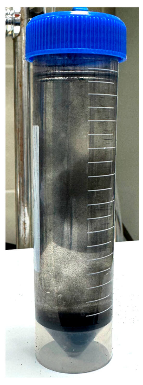
Figure 1.
Process of shungite elutriation.
For the elutriation of shungite, the following were used: a 400 mL tall beaker with a spout, a 5 mL Pasteur pipette, a vacuum rotary evaporator, and toluene of chemically pure grade. The choice of toluene as the elutriation solvent is explained by the fact that toluene extraction isolates α-carbyne contained in shungite. This carbon material exhibits enhanced Van der Waals interactions with carbon-chain polymers [38]. A 40 g sample of shungite was placed in the beaker, and 400 mL of toluene was added. During elutriation, the mixture was stirred with a glass rod and allowed to settle (Figure 1) for heavy particles to deposit. Using the pipette, 100 mL of the upper toluene layer containing suspended shungite particles was collected and transferred to a round-bottom flask. An additional 100 mL of fresh toluene was added to the beaker, and the elutriation process was repeated twice. After collecting 300 mL of toluene with suspended shungite particles, the round-bottom flask was transferred to the vacuum rotary evaporator, where toluene was distilled off at 58 °C and 100 mbar pressure. The resulting powder was dried in an oven at 105 °C to constant weight and used in subsequent work.
In addition to carbon, mineral shungite can contain silicates and carbonates, which determine the various properties and structure of the samples. To remove non-carbon components, chemical treatment of the initial samples of mechanoactivated shungite was performed using nitric acid HNO3 (65% concentration, density 1.4 g/cm3 according to GOST 701-89 [39], chemically pure grade) and hydrofluoric acid HF (40% concentration according to GOST 10484-78 [40], chemically pure grade) in a 1:1 volume ratio [41] at 100 °C for 2 h. The mass ratio of mechanoactivated shungite to the acid mixture was 1:1.
The reaction was carried out in a drying oven, with the shungite and acids placed in a fluoroplastic beaker housed within a desiccator (Figure 2). During the reaction, nitrogen oxide emission was observed. The resulting product was separated from the solution using a Büchner funnel No 1 (GOST 9147-80 [42], LLC Oyatskaya Keramika, Saint Petersburg, Russia) and washed with bidistilled water until a neutral pH was achieved. The obtained precipitate was then dried at T = 55 °C to constant weight.
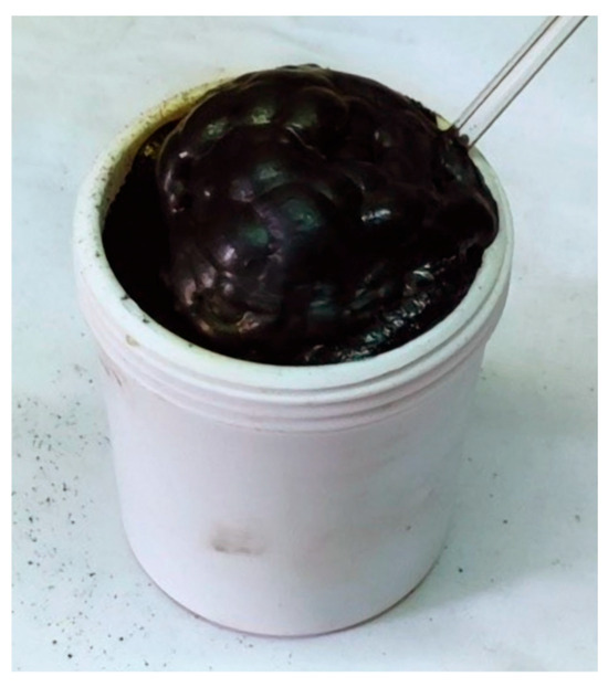
Figure 2.
Appearance of the shungite powder sample in an acid solution.
The studies used graphene powder RG-S1 (LLC “RUSGRAPHENE”, Moscow, Russia) with the manufacturer-declared characteristics: carbon content not less than 99%; microparticle thickness from 3 to 10 nm; microparticle diameter from 0.5 to 10 µm; specific surface area (by BET analysis)—15 m2/g.
As a gas black, a pigment for artistic works was used (LLC “Sibirskaya Palitra”, Novosibirsk, Russia, TU-20.12.24-008-03877465-2017) with a particle size of 10–30 nm.
For pilot field tests, chrysotile (GOST 12871-2013 [43], PJSC “Uralasbest”, Asbest, Russia) was used, which represents hollow tubes with an outer diameter of 30–40 nm, an inner diameter from 5 to 11 nm, and a length of 14–30 µm [44].
2.2. Determination of Dispersed Particle IR Spectra
IR spectra of gas black, graphene, and modified shungites samples were acquired using the Attenuated Total Reflection (ATR) method with a germanium crystal at a scanning frequency of 4 cm−1 on an FT-805 Fourier spectrometer (Simex, Novosibirsk, Russia). Spectra were recorded in the 300–4000 cm−1 wavenumber range. The ATR accessory enables analysis without specialized sample preparation.
It should also be noted that dispersions of carbon materials (carbon black and graphene) exhibit ≥99% purity per specifications, require no specialized purification or drying, remain stable under IR spectroscopy conditions (temperature, IR exposure), do not react chemically with the ATR crystal (diamond or germanium), and cause no damage to it. Samples of elutriated and acid-treated shungites were dried to constant weight.
Comparative IR spectroscopy of gas black, graphene, and modified shungites on diamond and germanium (Ge) crystals demonstrated that germanium substrates significantly enhance both the intensity of weak absorption bands and spectral resolution.
Gas black and graphene spectra (Figure 3) exhibit broad absorption bands at 3972–3400 cm−1 attributed to O–H stretching vibrations [45,46]. Weak signals at 1698–1460 cm−1 correspond to C=O carbonyl groups and C=C bonds in aliphatic/aromatic fragments of carbon materials. The presence of hydroxyl groups facilitates hydrogen bonding within polymer-gel composites and enables crosslinking between carbon materials and polyacrylamide/paraformaldehyde [47].
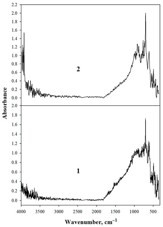
Figure 3.
IR spectra of: 1—gas black; 2—graphene.
The IR spectra of modified shungite samples—mechanoactivated, elutriated, and mechanoactivated followed by treatment with a mixture of nitric and hydrofluoric acids—exhibit distinctly different profiles and are presented in Figure 4.
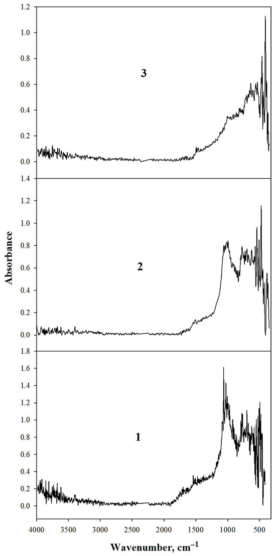
Figure 4.
IR spectra of shungite: 1—mechanoactivated; 2—elutriated, 3—acid-treated with HNO3/HF mixture.
The mechanoactivated shungite spectrum (≤20 μm particles) displays weak O–H peaks (3944–3183 cm−1). Absorptions at 1697, 1540, and 1473 cm−1 are assignable to C=O carbonyl vibrations and aromatic C=C bonds, corroborated by intense 777–698 cm−1 bands from aromatic C–H bending modes. The 1085 cm−1 peak is characteristic of carbon atoms in fullerene-like structures [38].
Intense 1063–1018 cm−1 bands correspond to stretching/bending vibrations of non-bridging Si–O bonds in silica groups [38], consistent with shungite’s elemental composition. These bands diminish after toluene elutriation and nearly disappear following acid treatment (Figure 4). Thus, both toluene elutriation and acid treatment effectively remove quartz and inorganic components from shungite surfaces, yielding novel carbon materials suitable as dispersed additives in gel-forming composites.
2.3. SEM Studies and Determination of Dispersed Particle Size
The particle size distribution of shungite was characterized utilizing micrographs acquired with a Tescan Vega 3LMN scanning electron microscope (Tescan, Brno-Kohoutovice, Czech Republic) operating in secondary electron detection mode. Particle size was measured using the Scale software [48]. Twenty to thirty measurements were performed per sample.
The appearance of modified shungite samples (elutriated and chemically treated) is shown in Figure 5. Analysis of SEM images of modified shungites revealed that the particles exhibit varied shapes and sizes, with both coarse and fine fractions present. As shungite is a mineral with a multicomponent chemical composition, particles with diverse crystallographic structures were observed in the powders.
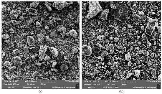
Figure 5.
SEM images of powders: (a) elutriated shungite; (b) chemically treated shungite.
The average particle size of modified shungite samples and the particle size distribution histograms (excluding large particles) are presented in Table 1 and Figure 6. For elutriated shungite, particles predominantly range from 24 to 47 μm, whereas after chemical treatment, 20 μm particles prevail, though large particles with an average size of 283 μm are also present.

Table 1.
Average particle size.
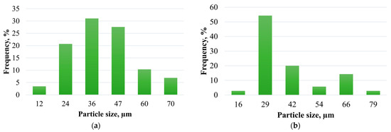
Figure 6.
Particle size distribution of: (a) elutriated shungite; (b) chemically treated shungite (fine fraction).
Energy-dispersive X-ray spectroscopy (EDS) quantitative elemental analysis of the shungite sample (initial, elutriated, and after chemical treatment) was performed using an AztecOne energy-dispersive microanalysis system (Oxford Instruments, High Wycombe, UK) coupled with a Tescan Vega 277 3LMN scanning electron microscope. The obtained data (Table 2) confirm the effectiveness of shungite acid treatment with an HNO3/HF mixture for quartz (SiO2) removal and are consistent with the results reported in study [41].
Table 2.
Elemental composition of shungite.
It should be noted that the complete removal of the silica component from shungite is nearly impossible, as SiO2 is only eliminated from the surface of the carbon matrix, which exhibits a globular structure composed of nanostructured graphite-like carbon. This is supported by data from IR spectroscopy and energy-dispersive X-ray elemental analysis.
2.4. Confocal Laser Microscope Studies
Emulsion samples before and after filtration on a low-permeability core were taken from the middle of the sample using a syringe without a needle. A drop of emulsion was placed on a glass slide, on which, on one side at some distance from the drop, a strip of foil 100 µm thick was placed. Then, a cover glass was placed over the drop and the foil. In this case, a gap was formed, preventing the flattening of the emulsion drops. The prepared specimen was placed on the stage of the Olympus FV3000 (Olympus Corporation, Tokyo, Japan) confocal laser microscope (Figure 7). Using the microscope software, a green laser (wavelength—561–568 nm) was selected, as well as the required magnification (40×).
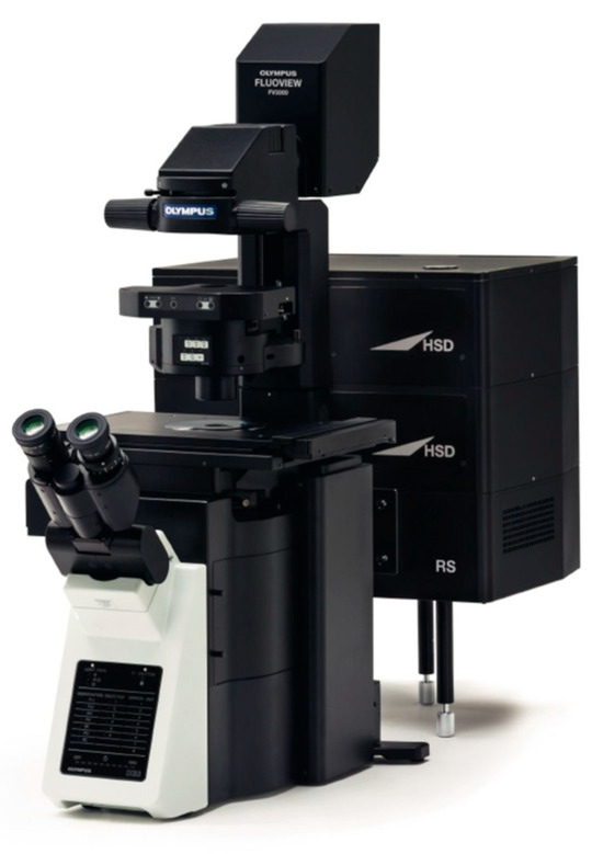
Figure 7.
Olympus FV3000 confocal laser microscope.
After focusing, images were obtained at 318 × 318 µm.
2.5. General Methodology for Preparing Polymer-Gel Composites with Carbon Dispersions
The dispersion of fillers was initially achieved in fresh water utilizing a magnetic stirrer over a period of 10–15 min, followed by the sequential addition of polymer and crosslinking agent. The resulting mixture was subsequently stirred for 45 min or until complete dissolution of the polymer was attained. Following a 48 h maturation period, oscillatory rheological measurements, and filtration studies were performed.
2.6. Viscoelastic Studies
Oscillatory rheological characterization was conducted with a Rheotest RN5.1 rotational viscometer (Rheotest Medingen GmbH, Ottendorf-Okrilla, Germany) featuring a plate-plate measuring system maintained at 24 °C. The measurement configuration employed a plate diameter (D) of 36 mm with an inter-plate gap (h) of 1 mm (Figure 8).
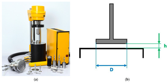
Figure 8.
Rotational viscometer Rheotest RN 5.1: (a) physical device; (b) plate-plate measuring geometry (D—plate diameter, h—inter-plate gap).
A precisely measured volume of hydrogel was deposited onto the lower plate using a calibrated syringe, after which the gap was set to 1 mm via micrometer adjustment. Any excess material was carefully removed with precision tweezers to ensure complete filling of the measurement gap without overflow.
Oscillatory tests were conducted under controlled stress sweep (τ) conditions at a constant frequency (ν) of 1 Hz. The primary rheological parameters quantified included: elastic modulus (G′), representing elastic response; viscous modulus (G″), characterizing viscous dissipation; complex modulus (G*); yield stress (determined at G′/G″ crossover point); and linear viscoelastic region (LVR) boundaries. Results represent the average of multiple measurements per sample.
2.7. Filtration Studies
Core sample preparation and filtration analysis were performed in compliance with the methodology outlined in reference [49]. The composite reservoir model was constructed using native core material extracted from the BS10 formation of a West Siberian oil field.
Filtration studies were conducted on the SMP FES-2R unit (LLC “KorTek”, Mytishchi, Russia). Technical characteristics of the unit: linear length of the core model 100–300 mm, temperature regulation range of the core 25–150 °C, maximum overburden pressure 70 MPa, maximum reservoir pressure 55 MPa.
2.7.1. Filtration Studies for Determining Residual Resistance Factor
For the experiments, five composite models were prepared from three individual core samples. The total length of the composite models was 9 cm, with absolute gas permeability ranging from 10.5 to 151.7 mD. The porous medium models were placed in the core holder of the SMP FES-2R core filtration setup and thermostated at 70 °C.
The models were saturated with oil and water to establish initial water and oil saturations. Oil was then displaced by water until the effluent stream reached full water cut. Subsequently, 0.3 pore volumes of the test composition were injected into the porous medium model. The system was then shut in under static conditions for at least 20 h.
Following this, water was injected in the reverse direction at a constant rate of 0.1 cm3/min until pressure stabilization. At each stage, permeability and maximum pressure differential were determined.
The residual resistance factor (RRF) was determined by calculating the ratio between the water differential pressure observed after treatment and the baseline differential pressure measured prior to treatment:
where dPi—differential pressure after treatment, MPa; dP1—baseline differential pressure, MPa.
2.7.2. Filtration Studies for Determining Water Shutoff Selectivity
All experiments were conducted at 70 °C. The initial stage involved oil flooding through the prepared core sample with established connate water saturation in the forward direction until pressure stabilization was achieved. Subsequently, water was injected in the same direction at a constant flow rate of 0.1 cm3/min until pressure stabilization, with relative permeability measurements recorded at each stage. Following this sequence, a blocking composition consisting of the base matrix containing 0.5% graphene was injected in the reverse direction relative to the initial flow, using a volume equivalent to 0.3 pore volumes. The system was then maintained under static conditions for a minimum of 48 h. The subsequent evaluation phase involved oil injection in the forward direction at 0.1 cm3/min until pressure stabilization, during which oil permeability was determined. This was followed by water injection under identical flow conditions until pressure stabilization, permitting the determination of water relative permeability. Finally, a comparative analysis was performed between the relative permeabilities to oil and water measured after the blocking composition injection.
2.8. Method for Well Killing with Simultaneous Treatment of the Near-Wellbore Zone with an Organic Solvent
Well killing is carried out according to the following sequence of operations: first, the blocking fluid—a Pickering invert emulsion stabilized by nanosilica—is pumped in a volume from the pump setting depth to the perforation interval. Then, the kill fluid—an aqueous solution of mineral salts (the density of the kill fluid should be slightly less than the density of the blocking fluid)—is pumped, and the blocking fluid is partially displaced into the formation. After which, tripping operations are carried out to change the pump by running the tubing string and setting the tubing shoe 1–2 m above the top of the productive formation. Then, with the casing valve open, organic solvent injection is continued in a volume equal to the tubing volume, with the kill fluid being dumped into the fill-up tank. After this, with the casing valve closed, organic solvent injection into the formation is continued at a volume of 1 m3 per 1 m of net pay thickness. The solvent is held in the formation for 8 h, and the well is put into operation. With this method, only the organic solvent enters the formation, which is pumped in the volume necessary for removing ARPD.
2.9. Pilot Field Test with Water Shutoff
In study [33], we investigated gel-forming compositions with a mineral filler—chrysotile, which showed high efficiency for isolating fractured reservoirs. Considering these positive results, this work presents the outcomes of a pilot field test (PFT) of a blocking composition based on chrysotile. PFTs were conducted on a field where the target productive reservoir is characterized by a fractured structure with a low-permeability hydrophilic matrix. Under such conditions, the main pathways for oil filtration to the wellbores are fractures, making the reservoir extremely vulnerable to water and gas breakthroughs, leading to complete isolation of oil reserves. Under such conditions, conducting water shutoff operations becomes increasingly relevant. The technology for injecting compositions during PFT repeats the technology from article [50], with the key difference being the introduction of chrysotile into the polymer slug composition.
3. Results and Discussion
3.1. Problem Statement
The development of low-permeability hydrophilic reservoirs is associated with complications arising from the structure of the pore space, as well as the properties of the rock surface and reservoir fluids [51]. In such reservoirs, a simple pump replacement always results in a prolonged well clean-up period, and often—failure to achieve the pre-shutdown oil production rate [17]. Since well killing during workovers and major repairs is the most frequent operation throughout a well’s life, improving well killing technology is an urgent task. An equally urgent task is combating premature water breakthrough, which allows the recovery of movable oil reserves without resorting to enhanced oil recovery (EOR) methods. To improve the efficiency of engineering operations during well workovers in low-permeability hydrophilic reservoirs, comprehensive analysis is required: geological-field studies, physical modeling of processes, and nanoscale/microscale visualization of applied materials (Meshalkin V.P., 2021) [52].
Table 3 illustrates the problem’s scale, showing the performance indicators of wells killed using mineral salt solutions as the kill fluid: in the first case—without prior placement of a blocking pill, and in the second—with prior placement of an invert emulsion blocking pill (emulsion-inverted solution). The data demonstrates that production decline occurs in all cases. Although for reservoirs with intermediate wettability, the use of invert emulsion blocking pills allows maintaining the pre-shutdown production rate, in low-permeability hydrophilic reservoirs, oil losses due to water blocking are observed. This occurs because emulsions break down during filtration in the porous medium, releasing the aqueous phase into the near-wellbore zone.
Table 3.
Oil losses following well killing in hydrophilic low-permeability reservoirs.
In our experiments, we simulated the well killing and cleanup process using a core flooding system under reservoir thermobaric conditions. The porous medium used had a permeability of 14.7 mD. During the initial stage, oil was filtered at a constant flow rate of 0.5 cm3/min.
Subsequently, the kill fluid—a NaCl solution with a density of 1.1 g/cm3—was injected in the reverse direction to the initial flow at a volume of 5 pore volumes (5 Vpore). The system was then subjected to a static shut-in period for two hours.
At the final stage, oil filtration was resumed in the original direction. The dynamic changes in parameters during this experiment are shown in Figure 9.
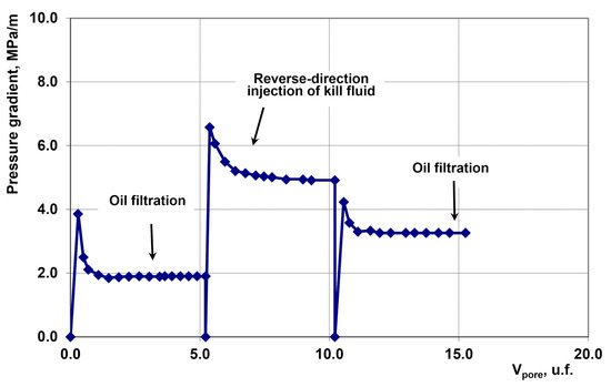
Figure 9.
Pressure Gradient Dynamics.
The permeability recovery factor was 0.583. Thus, nearly half of the oil permeability of the porous medium was lost.
The permeability restoration factor after well killing characterizes the degree of restoration of relative permeability to oil and is a constant value for a specific porous medium at a constant filtration rate. A significant reduction in oil permeability in low-permeability hydrophilic reservoirs occurs because the aqueous phase of the kill fluid is retained by the porous medium and not produced back during well flowback due to capillary water trapping. Consequently, water saturation increases in the near-wellbore zone, leading to reduced relative permeability to oil.
Table 4 presents well-killing simulation results for porous media with permeabilities ranging from 0.51 to 25.10 mD.
Table 4.
Results of oil permeability restoration factor determination at different absolute gas permeabilities.
It should be noted that the oil permeability restoration factor increases with higher absolute permeability, as larger pore throat radii reduce capillary water retention during simulated well flowback.
Another equally critical challenge in developing low-permeability hydrophilic reservoirs is combating premature water breakthrough in well production. To address this, the present work has developed selectively acting water shutoff materials based on polymer-inorganic composites.
3.2. Proposed Solution
The invention by Sergeev V. V. [19] solves the problem of well killing in low-permeability hydrophilic reservoirs. In Sergeev V. V.’s study [53], data demonstrated that an invert emulsion stabilized by an organic emulsifier and hydrophobic nanosilica filters through porous media without structural breakdown: only the emulsion globule size restructures according to pore size distribution. In our work, we reproduced the experiment from this study and confirmed no emulsion breakdown occurs (composition: hydrocarbon phase—33%, emulsifier Devon 4V Grade A—2%, nanosilica—2%), as evidenced by confocal microscopy images before and after filtration (Figure 10).
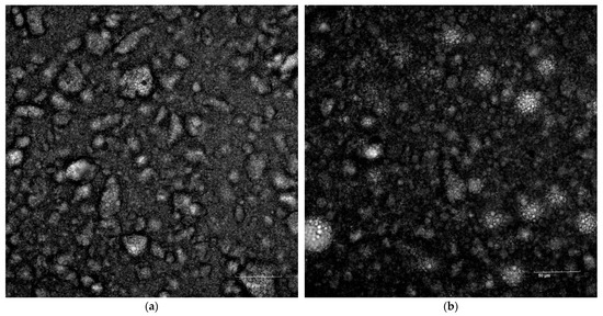
Figure 10.
Images of emulsion state: (a) Before filtration; (b) after filtration.
The rheological properties of this emulsion are presented in Table 5.
Table 5.
Rheological parameters of the emulsion.
As evident from Table 5, the sufficient yield stress values confirm that this emulsion can effectively prevent contact between the kill fluid and porous medium. Consequently, it is suitable for well killing in formations not complicated by ARPD in the near-wellbore zone.
It should be noted that stabilization of invert emulsions with organic amide-based emulsifiers combined with hydrophobic nanosilica significantly enhances the aggregation stability of Pickering emulsions. We prepared an emulsion for high-temperature reservoir applications consisting of 16% crude oil, 80% formation water, 3.8% emulsifier, and 0.2% hydrophobic nanosilica, and placed it in a thermostat at 90 °C for 15 h. The experiment revealed no water separation from the emulsion, and its rheological properties remained unchanged. Specifically, the emulsion’s yield stress was 41.5 Pa before thermal exposure and 42.0 Pa afterward.
For complications involving asphaltene or paraffin deposition, initial risk assessment using the De Boer diagram [54] is most advisable. Applying this methodology, we constructed De Boer diagrams for several fields where wells exhibited declining productivity indices during operation. For the Ust-Balyk field, asphaltene formation conditions in the BS1 and BS10 reservoirs fall within the high-risk zone; for the BS2–3 reservoir—the medium-risk zone (Figure 11). For the Yuzhno-Surgut field, wells in the YuS1 and YuS2 reservoirs are in the high-risk zone, while wells in the BS10 reservoir are in the medium-risk zone (Figure 12).
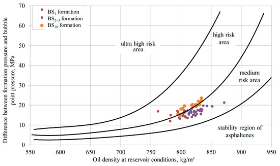
Figure 11.
Asphaltene deposition risk for Ust-Balyk field formations.
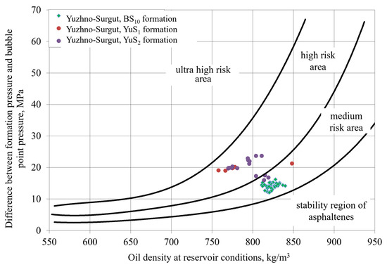
Figure 12.
Asphaltene deposition risk for Yuzhno-Surgut field formations.
Certain reservoirs exhibit conditions where the wax appearance temperature (WAT) of crude oil approaches temperatures in both the near-wellbore zone and wellbore tubing. Figure 13 presents the De Boer diagram for the Yanbayevskoye field, demonstrating stable asphaltenes but intensive precipitation of heavy oil components. Laboratory analysis revealed: silica-gel resin content—33.2%, asphaltenes—0.35%, paraffins—6.3%.
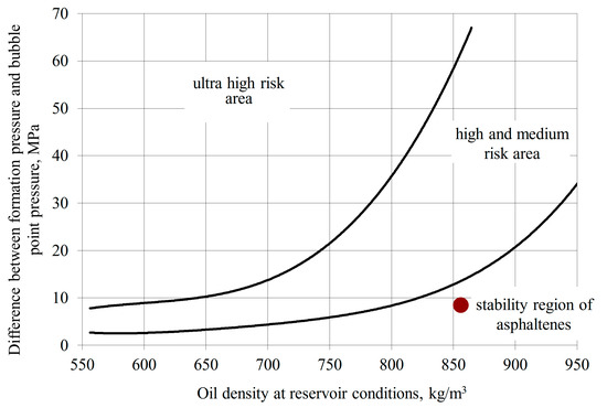
Figure 13.
Asphaltene deposition risk for Yanbayevskoye field formation.
When well productivity declines due to such deposits, well killing operations are integrated with production enhancement treatments. For asphaltene deposition, organic solvent treatments are implemented following the methodology in [22,25], with solvent injected at 1 m3 per meter of net pay thickness.
When paraffin deposition occurs after well killing, injection of paraffin inhibitors dissolved in crude oil or organic solvents is applied. The injection volume is taken at no less than 30 m3 per meter of net pay thickness. Polymer-based reagents are most suitable as paraffin inhibitors due to superior rock adsorption, effectively turning the near-wellbore zone into a sustained-release inhibitor source. An additional advantage of oil-soluble polymeric paraffin inhibitors is their resistance to water washout during increasing water cut. Such polymeric reagents include: styrene-maleic anhydride copolymer (polymerization degree ~300 for both monomers) modified with dibutyl- or hexadecylamine [55], ethylene-vinyl acetate copolymer with 30 wt% vinyl acetate content [56].
Pilot field tests of the combined well killing and solvent treatment technology were conducted on 10 wells in the BS10 reservoir of Ust-Balyk and Yuzhno-Surgut fields. Results showed 55.0 and 93.0 tons of incremental oil per m3 solvent for Ust-Balyk and Yuzhno-Surgut fields, respectively. Solvent: Neftras S4 130/350 (≤25 wt% aromatics), properties detailed in [24].
As evidenced, combined treatment in wells with asphaltenic deposits preserves production potential and enhances recovery by cleaning heavy components from the near-wellbore zone.
Well killing procedure for hydrophilic low-permeability reservoirs:
- No ARPD complications: Kill using Pickering emulsion stabilized by organic emulsifier/hydrophobic nanosilica with absorption monitoring;
- ARPD complications: Asphaltenes—treat with organic solvent; Paraffins—treat with polymeric paraffin inhibitor in organic solvent.
At water cut ≥60%, near-wellbore protection is ineffective. Focus shifts to injectors for profile conformance and displacement efficiency. In horizontal wells within hydrophilic reservoirs, permeability/saturation contrasts cause rapid water breakthrough from water-saturated intervals, blocking oil inflow via capillary imbibition. Thus, combating premature breakthroughs remains critical. Research focuses on waterflood front prediction in heterogeneous reservoirs [57,58], but prevention requires targeted interventions [59].
For water shutoff development, rheological/filtration experiments were conducted. Rheological studies aimed to maximize viscoelastic properties using carbon-based additives.
3.3. Oscillatory Test Results
During rheological studies, experience gained in previous works [33,60] was utilized. Specifically, when using hydrophilic nanosilica and polypropylene fibers as fillers in the same polymer-gel matrix, we established an optimal additive content range of 0.4–0.8%. These studies were conducted systematically with a filler concentration step of 0.1%. In the present work, the initial additive concentration was set at 0.5%, and experiments were terminated when the complex modulus decreased below its maximum value. Consequently, the extreme points of filler content differ for different composites.
Table 6.
Oscillatory Results.
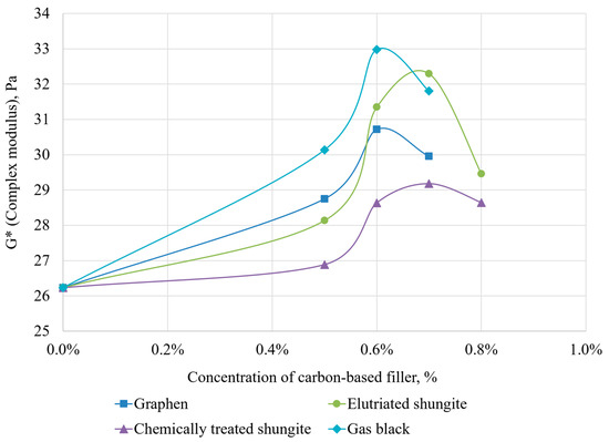
Figure 14.
Dependence of complex modulus on filler content and type.
The addition of fillers significantly increased the rheological properties of the hydrogel—elastic modulus, viscous modulus, and complex modulus—compared to the base composition. The present study confirms optimal range: maximum complex modulus values were achieved at 0.6–0.7% concentrations.
For graphene, the maximum complex modulus (30.72 Pa) occurs at 0.6% concentration, exceeding the base composition (26.24 Pa) by 17%. Other parameters (crossover point, LVR) changed marginally (≤3%).
For elutriated shungite, the optimal concentration is 0.7%, beyond which the complex modulus decreases significantly. Its peak value (32.3 Pa) surpasses the base hydrogel by 23%. At this concentration, near-maximum crossover point (45.33 Pa) and LVR (30.42 Pa) were observed versus 36.63 Pa and 23.25 Pa for the base composition.
Acid-treated shungite showed the least improvement: at 0.7% concentration, complex modulus reached 29.18 Pa (only 11% above base). Other parameters changed similarly. Based on these results, it can be concluded that further development of chemical treatment methods for shungite for use in blocking compositions is not practical.
The most significant result was obtained using gas black as an additive (optimal concentration: 0.6%): the complex modulus reached 32.98 Pa, which is 25.7% higher than the base value, while the crossover point (43.36 Pa) and LVR (29.82 Pa) showed increases of 18% and 14%, respectively.
Thus, all dispersions showed similar optimal concentrations (0.6–0.7%) for maximizing rheological properties. Best results were achieved with elutriated shungite and gas black.
The enhancement of rheological properties in nanoscale fillers (graphene and gas black) stems from Van der Waals force interactions with the polymer backbone. In the micro-sized filler—elutriated shungite—quartz is present, facilitating polymer interaction via hydrogen bonding with functional groups. Chemical treatment of mechanoactivated shungite dissolved the quartz component, which likely caused reduced rheological performance compared to elutriated shungite.
For context, our prior study with 0.4% nanosilica showed greater improvements: complex modulus (+55%), crossover point (+33%), LVR (+29%) versus base hydrogel [60].
It should be noted that the dependence of the complex modulus on the content and type of filler, presented in Figure 14, is typical for composite materials. As the filler concentration increases, the elastic modulus of the hydrogel increases due to the formation of cross-links between the macromolecules of the gel matrix and the filler. This process creates new nodes in the hydrogel’s network structure [61]. There exists an optimal filler concentration at which the hydrogel’s elasticity reaches its maximum. Further increases in filler concentration lead to a reduction in elasticity due to particle aggregation and the formation of defects in the hydrogel’s network structure. For example, study [62] observed an initial increase followed by a decrease in fracture strain and toughness.
In our research, a percolation threshold is evident at a concentration of 0.5% [63]. The relatively sharp decrease in the complex modulus after reaching the maximum can be attributed to the fact that the dispersion phase is water, in which the hydrophobic effects of carbon materials are pronounced. In our previous article [33], we successfully visualized the hydrophobic effect of carbon fiber dispersions in water. Particle aggregation occurs through Van der Waals interactions, which are particularly strong for graphene [64]. An interesting feature of the polyacrylamide-resorcinol-parafilm hydrogel system with various additives is that the percolation threshold and the maximum of elastic properties are observed at low filler concentrations, which is associated with the high cross-linking density within the hydrogel matrix.
3.4. Determination of Residual Resistance Factor for Composite with Gas Black at Optimal Concentration
A critical property of water shutoff materials is action selectivity, meaning that after injection into the target zone, residual phase permeability to water must be substantially lower than to oil.
To confirm the effectiveness of the best insulating composition according to rheometry data, we conducted five filtration experiments performed at different permeabilities of porous media with a gel containing gas black at the optimal concentration (Table 7).
Table 7.
Determination of residual resistance factor for composites with gas black at various permeabilities.
As evident from Table 7, the residual resistance factor increases as permeability decreases, with values ranging from 12.5 to 65.0, confirming the effectiveness of the blocking composition.
3.5. Hydrogel Selectivity
The polyacrylamide-resorcinol-parafilm water shutoff system has been used by us for 10 years for water shutoff, elimination of behind-casing flows, and sealing production casing leaks. The base gel, like most polyacrylamide gels [28], exhibits disproportionate permeability reduction, meaning permeability to water decreases significantly more than to oil. The wettability of the hydrophilic formation remains unchanged since the water shutoff material is inherently hydrophilic.
However, introducing hydrophobic dispersion into this system may alter wettability. As graphene is the most hydrophobic among all fillers we studied, we conducted the water shutoff selectivity test specifically with it. The chosen concentration of 0.5% is close to the optimal range but was slightly reduced due to cost considerations. This experiment was necessary to exclude the possibility of increased relative permeability to water, as it is well-known that hydrophobization of pore surfaces increases relative permeability to water [65].
Since one of the most critical properties of water shutoff materials is selectivity of action—meaning that after injecting the compositions into the target zone, the residual phase permeability to water must be significantly lower than the phase permeability to oil—we conducted a dedicated experiment. Table 8 presents the phase permeability measurements of a composite core model before and after injecting gel with graphene at a concentration of 0.5%.
Table 8.
Oil and water phase permeabilities before and after blocking composition injection.
Post-injection permeability to water was 0.08 mD, and to oil 0.54 mD. Thus, the gel-forming composition exhibits selective water shutoff properties, demonstrating disproportionate permeability reduction: oil permeability remained 6.75× higher than water permeability.
3.6. Water-Gas Shutoff Treatment in Well W9
Production well W9 with horizontal completion was drilled on 25 November 2018 with TD at 3395 m. Sharp gas/water breakthrough occurred on 20 March 2024 when GOR increased from 6321 to 8767 m3/t. At shutdown date 8 January 2025 for water-gas shutoff (WGS) treatment, well parameters: liquid rate (Qliq)—58.1 m3/d, water cut—71.7%; oil rate (Qoil)—13.6 t/d, gas-oil ratio (GOR)—20,916 m3/t.
Production fluid profile from well logs: water with oil/gas. Single-phase water inflow from 3003.4 to 3007.7 m (previously produced oil/water). Other intervals show mixed liquid (oil/water ratios) or gas–liquid (water/gas) near toe (3251.8–3333.8 m), with shifting/stable productive zones and new fractures activating. No well integrity issues detected.
WGS treatment performed: gas shutoff in 3255–3325 m water/gas interval, water shutoff in 2960–3030 m water interval. The treatment process is shown in Figure 15.
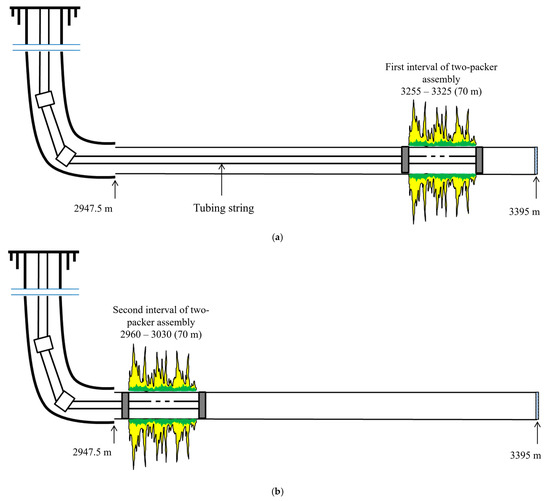
Figure 15.
WGS treatment using dual-packer assembly in Well W9: (a) Interval I treatment (3255–3325 m); (b) Interval II treatment (2960–3030 m).
Treatment plan:
- Install dual-packer assembly in 3255–3325 m and 2960–3030 m;
- Determine the injectivity of water intervals 3255–3325 m and 2960–3030 m with activated packer;
- For Interval I (3255–3325 m): Prepare 14 m3 foam-gel solution + 20 m3 base matrix with 0.15% chrysotile; inject below 200 atm;
- Displace with 11 m3 brine (density 1.17 g/cm3);
- For Interval II (2960–3030 m): Prepare 6 m3 foam-gel solution + 30 m3 base matrix with 0.15% chrysotile; inject below 200 atm;
- Displace with 10 m3 brine (1.17 g/cm3);
- Bleed pressure via tubing (casing closed). Disconnect lines. Retract packers;
- Static shut-in: 1 h (deactivate assembly).
WGS treatment completed 15 March 2025. Pre/post-treatment performance in Table 9 confirms gas/water shutoff success.
Table 9.
Well W9 performance before/after WGS treatment.
WGS Treatment Conclusions for Well W9:
- Pilot WGS treatment in 2960–3030 m and 3255–3325 m intervals was completed without complications per design;
- Treated zones covered 8 fluid-entry intervals;
- Liquid rate did not decrease post-treatment;
- After well production stabilization, oil rate increased from 13.6 to 32.2 t/d with water cut reduction from 71.7% to 47.5%;
- GOR decreased from 20,916 to 1258.6 m3/t;
- Bottomhole pressure reduced from 157 to 143 atm, confirming the expected colmatation effect resulting from WGS treatment;
- All parameters confirm successful gas/water shutoff in target intervals.
Based on the results of this study and the synthesis of our previous work [33,60], the following water shutoff procedure is recommended: for low-permeability granular hydrophilic reservoirs, apply composites with nanosilica, gas black, or elutriated shungite; for high-permeability granular and micro-fractured reservoirs, it is most advisable to use composites with chrysotile.
4. Conclusions
Thus, through comprehensive rheological and filtration experiments combined with field studies, accessible engineering solutions were identified to significantly enhance well workover and major repair efficiency in hydrophilic low-permeability reservoirs. For wells affected by heavy oil component deposition, integrated well killing with solvent treatment is proposed for asphaltene deposits in the near-wellbore zone, while paraffin inhibitors in organic solvent are recommended for paraffin deposition. Pilot tests across 10 wells at Ust-Balyk and Yuzhno-Surgut fields demonstrated specific technological effects of 55.0 and 93.0 tons of incremental oil per m3 of solvent, respectively.
For wells with premature water breakthrough, selective polymer–inorganic composites are proposed for isolation operations. Rheological studies identified an optimal filler concentration range of 0.6–0.7%, with elutriated shungite and gas black showing superior performance. These composites increased the complex modulus to 32.3 Pa and 32.98 Pa versus 26.24 Pa for the base composition. Filtration studies demonstrate that these composites with inorganic fillers exhibit a high residual resistance factor and selective action properties: residual permeability to oil is 6.75 times higher than to water. Field trials at an East Siberian field validated the composites’ efficiency: water cut decreased by ~25% and gas inflow was reduced fourfold within two months post-treatment.
Author Contributions
Conceptualization, V.M.; methodology, S.V., R.Y., V.D. and A.P. (Anatoly Politov); validation, F.S. and M.T.; formal analysis, A.E. A.V. and V.R.; investigation, A.P. (Artem Pavlik), R.A., R.G. and D.S.; resources, V.D., A.P. (Anatoly Politov), A.V. and V.R.; data curation, A.D.; writing—original draft preparation, A.T. and R.Y.; writing—review and editing, L.L.; visualization, R.A.; supervision, R.Y. and L.L.; project administration, L.L.; funding acquisition, V.M. All authors have read and agreed to the published version of the manuscript.
Funding
This research was funded by: the Russian Science Foundation (project No. 25-69-00012), the Science Committee of the Ministry of Science and Higher Education of the Republic of Kazakhstan (grant №AP26101849), the research project “Development of Acid Stimulation Technology with In Situ Diversion for Flow Profile Equalization in Carbonate Reservoirs”, implemented under the strategic project “New Technological Solutions for the Fuel and Energy Sector” of the USPTU Priority 2030 development program (Ufa State Petroleum Technological University).
Data Availability Statement
The original contributions presented in this study are included in the article. Further inquiries can be directed to the corresponding authors.
Conflicts of Interest
Author Sergey Vezhnin, Victor Ragulin, Farit Safarov and Aleksey Telin were employed by the company Ufa Scientific and Technical Center. Annaguly Deryaev was employed by the Scientific Research Institute of Natural Gas of the State Concern “Turkmengas”. The remaining authors declare that the research was conducted in the absence of any commercial or financial relationships that could be construed as a potential conflict of interest. The authors declare no conflicts of interest.
Abbreviations
The following abbreviations are used in this manuscript:
| NWZ | Near-wellbore zone |
| NMR | Nuclear magnetic resonance |
| SEM | Scanning electron microscopy |
| RPM | Relative permeability modifier |
| ARPD | Asphalt-resin-paraffin substances deposit |
| WAT | Wax appearance temperature |
| BM | Base matrix |
| PAM | Polyacrylamide |
| ATR | Attenuated total reflection |
| LVR | Linear viscoelastic region |
| PFT | Pilot field test |
| EOR | Enhanced oil recovery |
| WGS | Water-gas shutoff |
| GOR | Gas-oil ratio |
References
- Li, Q.; Li, Q.; Han, Y. A Numerical Investigation on Kick Control with the Displacement Kill Method during a Well Test in a Deep-Water Gas Reservoir: A Case Study. Processes 2024, 12, 2090. [Google Scholar] [CrossRef]
- Mardashov, D.V. Development of blocking compositions with a bridging agent for oil well killing in conditions of abnormally low formation pressure and carbonate reservoir rocks. J. Min. Inst. 2021, 251, 667–677. [Google Scholar] [CrossRef]
- Li, Y.; Jiang, G.; Li, X.; Yang, L. Quantitative Investigation of Water Sensitivity and Water Locking Damages on a Low-Permeability Reservoir Using the Core Flooding Experiment and NMR Test. ACS Omega 2022, 7, 4444–4456. [Google Scholar] [CrossRef] [PubMed]
- Olekhnovich, R. Laboratory Study of Compatibility of Kill Fluids with Formation Water. In Proceedings of the 19th SGEM International Multidisciplinary Scientific Geo Conference EXPO, Albena, Bulgaria, 28 June–7 July 2019. [Google Scholar] [CrossRef]
- Pan, L.; Liu, H.; Long, W.; Li, J.; Li, J.; Liu, Q. A Novel Foamy Well Killing Fluid for Low-Pressure Gas Reservoirs in Tarim Basin, China. In Proceedings of the International Petroleum Technology Conference, Virtual, 16 March–1 April 2021. [Google Scholar] [CrossRef]
- Eaton, B.A.; Smithey, M. Formation Damage from Workover and Completion Fluids. In Proceedings of the SPE California Regional Meeting, Los Angeles, CA, USA, 4–5 November 1971. [Google Scholar] [CrossRef]
- Radwan, A.E.; Wood, D.A.; Abudeif, A.M.; Attia, M.M.; Mahmoud, M.; Kassem, A.A.; Kania, M. Reservoir Formation Damage; Reasons and Mitigation: A Case Study of the Cambrian–Ordovician Nubian ‘C’ Sandstone Gas and Oil Reservoir from the Gulf of Suez Rift Basin. Arab. J. Sci. Eng. 2022, 47, 11279–11296. [Google Scholar] [CrossRef]
- Civan, F. Reservoir Formation Damage: Fundamentals, Modeling, Assessment, and Mitigation, 4th ed.; Gulf Professional Publishing: Cambridge, MA, USA, 2023; 1069p, ISBN 978-0-323-90228-1. [Google Scholar]
- Zhao, X.; Qiu, Z.; Sun, B.; Liu, S.; Xing, X.; Wang, M. Formation Damage Mechanisms Associated with Drilling and Completion Fluids for Deepwater Reservoirs. J. Pet. Sci. Eng. 2019, 173, 112–121. [Google Scholar] [CrossRef]
- Del Rio, C.; Boucher, A.; Salazar, F.; Milne, A.; Robles, M. Temporary Zonal Isolation Minimizes Reservoir Damage During Workover Operations in Ecuador. In Proceedings of the SPE European Formation Damage Conference, Noordwijk, The Netherlands, 7–10 June 2011. [Google Scholar] [CrossRef]
- Mohamed, Y.A.E.-A.; El-Gindy, A.T.; El-Agamy, H.A.; Moustafa, A.I.; Eissa, A.M.; Akeel, M.M. Field Application of Newly Designed Non-Damaging Sealing Killing Fluid to Control Losses in Completion and Workover Operations in Western Desert, Egypt. In Proceedings of the SPE Trinidad and Tobago Section Energy Resources Conference, Virtual, 28–30 June 2021. [Google Scholar] [CrossRef]
- Alarcon, X.; Doghmi, A.; Ahmed, M.; Tellez, J.; Alvarez, J.; Chuc, E.; Masoodi, A. Implementing a Solids-Free, Non-Damaging Loss Control Solution to Enable Overbalanced Workover Interventions: Case Studies and Applications from 80+ Wells in Iraq. In Proceedings of the ADIPEC, Abu Dhabi, United Arab Emirates, 4–7 November 2024. [Google Scholar] [CrossRef]
- Khan, R.A.; Tariq, Z.; Murtaza, M.; Kamal, M.S.; Mahmoud, M.; Abdulraheem, A. Ionic Liquids as Completion Fluids to Mitigate Formation Damage. J. Pet. Sci. Eng. 2022, 214, 110564. [Google Scholar] [CrossRef]
- Hanshi, Z.; Guancheng, J.; Hongxun, B.; Kuanliang, Z. Research on Protecting Formation Low-Damage Workover Fluid in Low Permeability Reservoir. Int. J. Nanosci. 2019, 18, 1850049. [Google Scholar] [CrossRef]
- Shaidullin, V.A.; Khatmullin, A.R.; Turiyanov, A.R.; Mingalishev, F.K. Variable Approach to the Killing Fluids Selection for Sandstone Formations. Part 2. Core Testing of Killing Fluids Influence on Rock Permeability. Expo. Oil Gas 2024, 1, 38–42. [Google Scholar] [CrossRef]
- Glushchenko, V.; Khizhnyak, G. Directions for Improving the Compositions of Reverse Emulsions for Well Plugging. Perm J. Pet. Min. Eng. 2023, 23, 44–50. [Google Scholar] [CrossRef]
- Saduakasov, D.S.; Zholbasarova, A.T.; Bayamirova, R.U.; Togasheva, A.R.; Tabylganov, M.T.; Sarbopeeva, M.D.; Kasanova, A.G.; Gusakov, V.N.; Telin, A.G. Well Killing with Absorption Control. J. Min. Inst. 2025, 272, 119–135. [Google Scholar]
- Khakimov, A.M.; Makatrov, A.K.; Karavaev, A.D.; Telin, A.G.; Smykov, Y.V.; Khalimov, R.K.; Kuramshin, Y.R. Filtration Testing of a New Generation of Domestic and Foreign Surfactants as Additives to Repair and Technological Fluids during Underground Repairs and Wellbore Maintenance in Hydrophilic Reservoirs. Oilfield Eng. 2005, 12, 48–53. [Google Scholar]
- Sergeev, V.V. Method of Killing Oil and Gas Wells. Russian Patent No. 2659046, 27 June 2018. [Google Scholar]
- Islamov, S.; Islamov, R.; Shelukhov, G.; Sharifov, A.; Sultanbekov, R.; Ismakov, R.; Agliullin, A.; Ganiev, R. Fluid-Loss Control Technology: From Laboratory to Well Field. Processes 2024, 12, 114. [Google Scholar] [CrossRef]
- Leontaritis, K.J.; Amaefule, J.O.; Charles, R.E. A Systematic Approach for the Prevention and Treatment of Formation Damage Caused by Asphaltene Deposition. SPE Prod. Facil. 1994, 9, 157–164. [Google Scholar] [CrossRef]
- Voloshin, A.I.; Ragulin, V.V.; Telin, A.G. Development and Introduction of Heavy Organic Compound Deposition Diagnostics, Prevention and Removing. In Proceedings of the SPE International Symposium on Oilfield Chemistry, Woodlands, TX, USA, 2–4 February 2005. [Google Scholar] [CrossRef]
- Zeygman, Y.V.; Mukhametshin, V.S.; Khafizov, A.R.; Kharina, S.B.; Abutalipova, E.M.; Avrenyuk, A.N. Peculiarities in Selection of Well-Killng Fluids Composition for Difficult Conditions. Oil Ind. 2017, 1, 66–69. [Google Scholar]
- Stekolshchikov, M.N. Hydrocarbon Solvents: Properties, Production, Application; Chemistry: Moscow, Russia, 1986; 120p. [Google Scholar]
- Shutkova, S.A.; Dolomatov, M.Y.; Telin, A.G. Unusual Patterns of Interaction of Asphaltenes with Aprotonic Solvents. Oil Gas Stud. 2024, 4, 147–158. [Google Scholar] [CrossRef]
- Kuangaliev, Z.; Doskaziyeva, G.; Mardanov, A. Solving the Problems of Water Cut in Production Wells of Oil Fields. Sci. Herit. 2019, 40, 30–34. [Google Scholar]
- Cao, J.; Liu, Z.; Zhang, Z.; Wang, Y.; Wang, L. Analysis of Waterflooding Oil Recovery Efficiency and Influencing Factors in the Tight Oil Reservoirs of Jilin Oilfield. Processes 2025, 13, 1490. [Google Scholar] [CrossRef]
- Seright, R.; Brattekas, B. Water Shutoff and Conformance Improvement: An Introduction. Pet. Sci. 2021, 18, 450–478. [Google Scholar] [CrossRef]
- Cui, X.; Wang, C.; Huang, W.; Zhang, S.; Chen, H.; Wu, B.; Qin, D.; Zheng, X. Multiple Hydrogen Bonding-Assisted High-Strength Hydrogel of Silica/Polyacrylamide Nanocomposite Cross-Linked with Polyethylenimine. ACS Omega 2023, 8, 39401–39407. [Google Scholar] [CrossRef]
- Sun, D.; Yang, Y.; Liu, Y.; Wu, Z.; Zhang, H. Strengthening the Hydrogel for Lost Circulation Control through In Situ Self-Assembled Nanocomposite Networks. Energy Fuels 2023, 37, 4320–4330. [Google Scholar] [CrossRef]
- Cong, H.-P.; Wang, P.; Yu, S.-H. Highly Elastic and Superstretchable Graphene Oxide/Polyacrylamide Hydrogels. Small 2014, 10, 448–453. [Google Scholar] [CrossRef]
- Michael, F.M.; Krishnan, M.R.; AlSoughayer, S.; Busaleh, A.; Almohsin, A.; Alsharaeh, E.H. Thermo-Elastic and Self-Healing Polyacrylamide -2D Nanofiller Composite Hydrogels for Water Shutoff Treatment. J. Pet. Sci. Eng. 2020, 193, 107391. [Google Scholar] [CrossRef]
- Telin, A.; Yakubov, R.; Pavlik, A.; Dokichev, V.; Gallyamova, R.; Mamykin, A.; Safarov, F.; Strizhnev, V.; Vezhnin, S.; Politov, A.; et al. Development of Polymer–Gel Fibrous Composites for Well Water Shutoff in Fractured–Porous Carbonate Formations. Polymers 2025, 17, 1541. [Google Scholar] [CrossRef] [PubMed]
- Meshalkin, V.; Akhmetov, A.; Lenchenkova, L.; Nzioka, A.; Politov, A.; Strizhnev, V.; Telin, A.; Fakhreeva, A. Application of Renewable Natural Materials for Gas and Water Shutoff Processes in Oil Wells. Energies 2022, 15, 9216. [Google Scholar] [CrossRef]
- Ignatov, I.; Mosin, O. Research of Influence of Shungite for Ctivation of Mountain Water from Different Mountain Sources. J. Health Med. Nurs 2015, 12, 1–18. [Google Scholar]
- Volkova, E.R. Catalytic Properties of Shungite in Reactions of Urethan Formation. Inorg. Mater. Appl. Res. 2021, 21, 224–229. [Google Scholar] [CrossRef]
- Kovalevskia, V.V.; Kochneva, I.V.; Rozhkova, V.S. Sorption Properties of Natural and Modified Shungite Rocks Differing in Origin. Inorg Mater 2023, 59, 736–741. [Google Scholar] [CrossRef]
- Baykova, L.A.; Nikonenko, E.A.; Kosareva, M.A.; Gabdullin, A.N.; Ahatov; Kayumov, R.R. Investigation of the Systems “Shungit-Toluen” and “Shungyt-Water” by Spectroscopic Methods. Butlerov Commun. 2018, 53, 119–126. [Google Scholar]
- GOST 701-89; Concentrated Nitric Acid. Specifications. Publishing and Polygraphic Complex; Standards Publishing House: Moscow, Russia, 2002.
- GOST 10484-78; Reagents. Hydrofluoric Acid. Specifications. Publishing and Polygraphic Complex; Standards Publishing House: Moscow, Russia, 1998.
- Sukhinina, N.S.; Khodos, I.I.; Zver’kova, I.I.; Turanov, A.N.; Karandashev, V.K.; Emel’chenko, G.A. Structural Features and Sorption Properties of Mesoporous Carbon Material Prepared from Natural Shungite. Inorg. Mater. 2022, 58, 1114–1121. [Google Scholar] [CrossRef]
- GOST 12871-2013; Chrysotile. General Specifications; FSUE STANDARTINFORM: Moscow, Russia, 2015.
- GOST 9147-80; Laboratory Porcelain Ware and Apparatus. Specifications; FSUE STANDARTINFORM: Moscow, Russia, 2011.
- Smolikov, A.A.; Kostin, V.V. Industrial Technology for Obtaining Chrysotile Monofibres. Bull. Belgorod State Technol. Univ. Named After V.G. Shukhov 2009, 2, 13–16. [Google Scholar]
- Sugatri, R.I.; Wirasadewa, Y.C.; Saputro, K.E.; Muslih, E.Y.; Ikono, R.; Nasir, M. Recycled Carbon Black from Waste of Tire Industry: Thermal Study. Microsyst. Technol. 2018, 24, 749–755. [Google Scholar] [CrossRef]
- Wazir, A.H.; Kundi, I.W. Synthesis of Graphene Nano Sheets by the Rapid Reduction of Electrochemically Exfoliated Graphene Oxide Induced by Microwaves. J. Chem. Soc. Pak. 2016, 38, 11–16. [Google Scholar]
- Cairns, T.L.; Foster, H.D.; Larchar, A.W.; Schneider, A.K.; Schreiber, R.S. Preparation and Properties of N-Methylol, N-Alkoxymethyl and N-Alkylthiomethyl Polyamides. J. Am. Chem. Soc. 1949, 71, 651–655. [Google Scholar] [CrossRef]
- Scale Software. Available online: https://antropol.narod.ru/Scale.zip (accessed on 12 June 2025).
- OST 39-195-86; Oil. Method of Determining the Coefficient of Displacement of Oil by Water in the Laboratory. RussianGost: Moscow, Russia, 1986.
- Telin, A.; Karazeev, D.; Vezhnin, S.; Strizhnev, V.; Levadsky, A.; Mamykin, A.; Lenchenkova, L.; Yakubov, R.; Fakhreeva, A.; Akhmetov, A.; et al. Use of Self-Generating Foam Gel Composition with Subsequent Injection of Hydrogel to Limit Gas Inflow in Horizontal Wells of Vostochno-Messoyakhskoye Field. Gels 2024, 10, 215. [Google Scholar] [CrossRef]
- Mazaev, V.V.; Zemtsov, Y.V.; Alexandrov, V.N. Application of Physicochemical Methods for Enhanced Oil Recovery in Jurassic Reservoirs of Western Siberia; LLC “Poligrafmarket”: Tyumen, Russia, 2024; 280p. [Google Scholar]
- Meshalkin, V.P.; Dovì, V.G.; Bobkov, V.I.; Belyakov, A.V.; Butusov, O.B.; Garabadzhiu, A.V.; Burukhina, T.F.; Khod-Chenko, S.M. State of the Art and Research Development Prospects of Energy and Resource-Efficient Environmen-tally Safe Chemical Process Systems Engineering. Mendeleev Commun. 2021, 31, 593–604. [Google Scholar] [CrossRef]
- Sergeev, V.V.; Russkikh, K.G.; Zeigman, Y.V.; Yakubov, R.N. Experimental Research of the Impact of Filtration Processes on the Dispersity of Emulsion Systems with Nanoparticles. Nanobuild 2019, 11, 31–41. [Google Scholar] [CrossRef]
- De Boer, R.B.; Leerlooyer, K.; Eigner, M.R.P.; Van Bergen, A.R.D. Screening of Crude Oils for Asphalt Precipitation: Theory, Practice, and the Selection of Inhibitors. SPE Prod. Facil. 1995, 10, 55–61. [Google Scholar] [CrossRef]
- Puzin, Y.I.; Mastobaev, B.N.; Puzin, P.Y.; Smolnikova, T.V. Inhibition of the Paraffin Deposits by Using of Copoly (Styrene2maleic Anhydride) to Be Modified by Amine. Oil Gas Chem. 2017, 1, 36–39. [Google Scholar]
- Korobov, G.Y.; Parfenov, D.V.; Nguyen, V.T. Long-Term Inhibition of Paraffin Deposits Using Porous Ceramic Proppant Containing Solid Ethylene-Vinyl Acetate. IJE 2025, 38, 1887–1897. [Google Scholar] [CrossRef]
- Wang, C.; Sun, Z.; Sun, Q.; Zhang, L.; Zhang, X. Comprehensive Evaluation of Waterflooding Front in Low-permeability Reservoir. Energy Sci. Eng. 2021, 9, 1394–1408. [Google Scholar] [CrossRef]
- Palyanitsina, A.; Tananykhin, D.; Masoud, R. Strategy of Water-Flooding Enhancement for Low-Permeable Polymictic Reservoirs. J. Appl. Eng. Sci. 2021, 19, 307–317. [Google Scholar] [CrossRef]
- Shcherbakova, K.O. The Problem of High Water Cut in the Products of Horizontal Wells. Proc. High. Educ. Establ. Geol. Explor. 2023, 6, 29–38. [Google Scholar] [CrossRef]
- Telin, A.; Safarov, F.; Yakubov, R.; Gusarova, E.; Pavlik, A.; Lenchenkova, L.; Dokichev, V. Thermal Degradation Study of Hydrogel Nanocomposites Based on Polyacrylamide and Nanosilica Used for Conformance Control and Water Shutoff. Gels 2024, 10, 846. [Google Scholar] [CrossRef]
- Thoniyot, P.; Tan, M.J.; Karim, A.A.; Young, D.J.; Loh, X.J. Nanoparticle–Hydrogel Composites: Concept, Design, and Applications of These Promising, Multi-Functional Materials. Adv. Sci. 2015, 2, 1400010. [Google Scholar] [CrossRef]
- Liu, Y.; Meng, H.; Konst, S.; Sarmiento, R.; Rajachar, R.; Lee, B.P. Injectable Dopamine-Modified Poly(Ethylene Glycol) Nanocomposite Hydrogel with Enhanced Adhesive Property and Bioactivity. ACS Appl. Mater. Interfaces 2014, 6, 16982–16992. [Google Scholar] [CrossRef]
- Irzhak, V.I. Percolation threshold in polymer nanocomposites. Colloid J. 2021, 83, 51–56. [Google Scholar] [CrossRef]
- Katsnelson, M.I. The Physics of Graphene, 2nd ed.; Cambridge University Press: Cambridge, UK, 2020; ISBN 978-1-108-61756-7. [Google Scholar]
- Craig, F.F. The Reservoir Engineering Aspects of Waterflooding; SPE: Dallas, TX, USA, 1971; 135p. [Google Scholar]
Disclaimer/Publisher’s Note: The statements, opinions and data contained in all publications are solely those of the individual author(s) and contributor(s) and not of MDPI and/or the editor(s). MDPI and/or the editor(s) disclaim responsibility for any injury to people or property resulting from any ideas, methods, instructions or products referred to in the content. |
© 2025 by the authors. Licensee MDPI, Basel, Switzerland. This article is an open access article distributed under the terms and conditions of the Creative Commons Attribution (CC BY) license (https://creativecommons.org/licenses/by/4.0/).