Abstract
Network protector units (NPUs) are crucial parts of the protection of secondary networks to effectively isolate faults occurring on the primary feeders. When a fault occurs on the primary feeder, there is a path of the fault current going through the service transformers that causes a negative flow of current on the NPU connected to the faulted feeder. Conventionally, NPUs rely on the direction of current with respect to the voltage to detect faults and make a correct trip decision. However, the conventional NPU logic does not allow the reverse power flow caused by distributed energy resources installed on secondary networks. The communication-assisted direct transfer trip logic for NPUs can be used to address this challenge. However, the communication-assisted scheme is exposed to some vulnerabilities arising from the disruption or corruption of the communicated data that can endanger the reliable operation of NPUs. This paper evaluates the impact of the malfunction of the communication system on the operation of communication-assisted NPU logic. To this end, the impact of packet modification and denial-of-service cyberattacks on the communication-assisted scheme are evaluated. The evaluation was performed using a hardware-in-the-loop (HIL) co-simulation testbed that includes both real-time power system and communication network digital simulators. This paper evaluates the impact of the cyberattacks for different fault scenarios and provides a list of recommendations to improve the reliability of communication-assisted NPU protection.
1. Introduction
Secondary low voltage networks are a part of distribution systems operating at lower voltage and delivering electric power directly to end users, like residential, commercial, and small industrial customers. Secondary networks are vital for powering critical facilities in highly populated locations due to their meshed architecture with redundant equipment feeding the customers at all times [1]. In situations such as extreme weather or when a utility pole is struck by a vehicle, the high reliability of secondary networks becomes essential for maintaining power supply to critical loads [2]. To support the resilience and reliability of these systems, continuous research and development of protective measures are essential. To ensure power reliability for critical customers, spot networks typically use two or more service transformers connected to a single customer [2,3]. Figure 1 illustrates a typical secondary network with two low voltage (LV) spot networks. When a fault occurs on any of the primary feeders, the substation relay detects the fault and opens its breaker to de-energize the faulted feeder. However, even after the breaker opening, there is still a path for the fault current to flow from the other primary feeder through the spot network and back up to the fault location [4,5]. Therefore, to fully isolate the fault, a protection device is required to disconnect service transformers when reverse power flow occurs. For this purpose, secondary networks rely on network protector units (NPUs). An NPU is a protection device that can disconnect its service transformer from the secondary network if it detects reverse power flow toward the primary system [6].
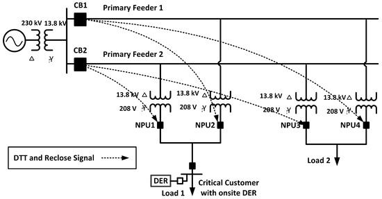
Figure 1.
Test system with two spot networks and DER.
The conventional NPU logic faces two significant challenges. First, when the service transformer connecting to the LV spot network has a delta winding on the primary feeder side, the NPU may fail to detect ground faults on the primary network. The reason is that when a ground fault occurs on the delta side of the transformer, the delta winding acts as an open circuit in the zero sequence network and blocks the flow of zero sequence currents on the Wye side where the NPU is located. This results in small reverse current flowing through the NPU, which may be below the NPU’s reverse current threshold. Additionally, because the grounding of the medium-voltage feeders is provided by the substation transformer, after the substation breaker opens, it becomes a three-wire ungrounded system where ground faults do not create a fault current [7]. Secondly, while the NPU logic effectively isolates upstream grid faults in the absence of distributed energy resources (DERs), it also blocks reverse power flow from DERs. For instance, in Figure 1, assume that Load 1 is a critical customer like a hospital or community center that has an onsite DER for backup generation. When the DER’s generation is greater than Load 1, NPU 1 and 2 will experience reverse flow of power and current. If the amount of the reverse flow of current is greater than the NPU’s reverse current threshold, NPU 1 and 2 will mistakenly trip during this non-fault and normal operation. As a result, all DER-generated power must be used or stored locally, which greatly limits the DER’s potential benefits to support the loads of other spot networks (e.g., Load 2) [8,9,10].
One method to permit reverse power flow from DERs is to adjust the NPU settings by reducing sensitivity. However, this desensitization brings challenges: (i) it could permit reverse current flow from high impedance faults (compromising reliability), (ii) it may allow reverse flow during maintenance (a safety risk), and (iii) it may still fail to detect ground faults if the secondary transformer has a delta winding on the primary side. To address these issues, a direct transfer trip (DTT) from the upstream relay on the primary feeder can help the NPU reliably differentiate fault from non-fault situations. The previous work of authors in [11], discussed a DTT scheme for the protection of secondary networks, where the NPU relies primarily on DTT signals from the upstream primary relay to identify faults on the primary feeder. In [11], the performance of the communication-assisted scheme is extensively compared against the conventional NPU protection. As a local backup, the NPU’s conventional logic activates if no transfer trip signal is received. In an LV network with DERs, the NPU uses desensitized settings set above the service transformer’s current rating, allowing reverse power flow from DERs while also detecting high current phase faults on the primary network. When no DERs are present in the LV network, the NPU’s conventional local protection logic serves as a backup to the DTT scheme.
The communication-assisted protection logic for NPUs requires a local network to transmit the trip or reclose commands from the upstream substation relay to the local NPU units [12]. One of the major challenges of the communication-assisted scheme is its reliance on the communication network that is exposed to the potential disruption or corruption of the communicated data as a result of cyberattacks or other outages. Common cyberattacks that can compromise the performance of the communication-assisted NPU logic are denial-of-service (DOS) [13,14] and packet modification attacks [15,16]. DOS attacks can include Transmission Control Protocol Synchronization (TCP SYN) [17] and IP fragmentation [18], which can overwhelm the NPUs or substation relays and endanger their proper operation. On the other hand, a packet modification attack can take control of the transmitted signal to NPUs and deliver a corrupted value. For example, the attacker can invert the DTT signal when there is no fault in the system to deceive NPUs so that they trip and disconnect the spot network load. The goal of this paper is to study and evaluate these scenarios and identify the practical approaches that can mitigate them. The contributions of this paper are as follows:
- Although the communication-assisted protection of secondary networks has been addressed and utilized, its vulnerability to the communication network disruption is not evaluated in the literature. This paper bridges this gap by evaluating the cyber security of an NPU in the presence of a communication-assisted scheme and provides a list of suggestions for mitigating the impacts.
- This paper investigates the impact of DOS and packet modification (an example of a False Data Injection attack) cyberattacks on the communication-assisted logic of NPUs using a co-simulation hardware-in-the-loop (HIL) testbed that includes both real-time power system and communication network digital simulators.
The rest of paper is organized as follows: Section 2 discusses the communication-assisted NPU’s logic using a DTT scheme. In Section 3, the cyber security risks of the DTT scheme are discussed and the mechanisms of the DOS and packet modification attacks are briefly elaborated. Section 4 introduces the HIL testbed utilized for the evaluation of the cyberattacks on the DTT scheme. Section 5 summarizes the experimental results gathered from the cyberattack studies using the HIL testbed. Section 6 concludes the paper by providing a list of mitigative actions for tackling cyberattacks in secondary networks.
2. NPU Logic
In the following, first, the conventional local protection logic of NPUs for both tripping and reclosing actions are elaborated. Then, the communication-assisted protection logic is discussed. It should be noted that an NPU may operate using either conventional local protection logic, communication-assisted protection logic, or both.
2.1. Conventional Local NPU’s Trip Logic
The conventional local logic in NPUs incorporates two tripping elements: one instantaneous (less sensitive) and one delayed (more sensitive). The less sensitive element has a higher pickup current value with a five-cycle delay, ensuring the NPU does not trip immediately during transient events or before the upstream protective device operates. Conversely, the delayed element, with a lower pickup current and a longer delay (this delay depends on the utility practice and is typically around 10 s), prevents the NPU from tripping for transients resulting in a lower reverse current flow. For tripping, the NPU evaluates the magnitude of the positive sequence current at the LV side of the service transformer and the phase angle difference between the positive sequence current and voltage phasors. The NPU’s angle settings allow it to accurately distinguish between forward and reverse current flow relative to the voltage phasor. Figure 2 displays a typical NPU reverse current trip characteristic diagram. This characteristic uses the positive sequence current phasor measured at the NPU location with the direction toward the spot network load. The positive sequence current phasor angle is calculated assuming the NPU’s positive sequence voltage phasor angle as the reference. In Figure 2, the area above the blue line indicates the normal operating region, allowing for some reverse current flow from DERs. The area below the blue line represents the trip region: if the current magnitude lies between the blue and orange lines, the NPU trips with a delay; if it exceeds the orange threshold, the NPU trips instantaneously.
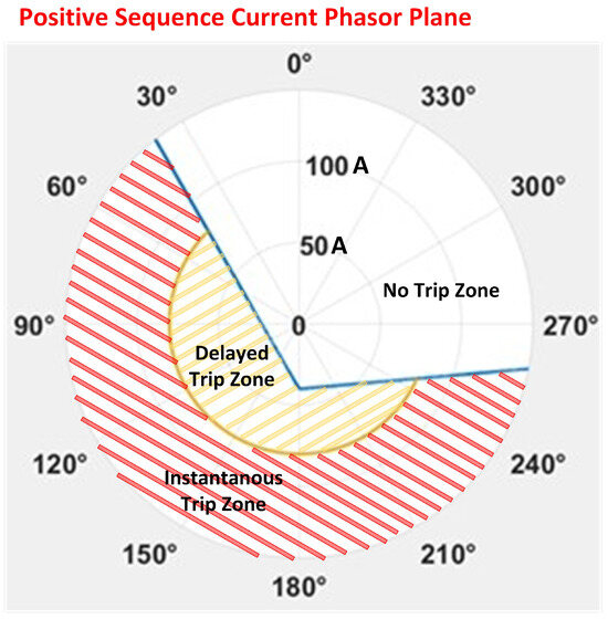
Figure 2.
NPU reverse trip characteristic based on positive sequence current phasor (phasor’s angle is calculated with respect to the positive sequence voltage phasor angle).
2.2. Conventional Local NPU’s Reclose Logic
In secondary networks, the NPU’s reclosure is delayed until after the primary circuit’s head-end breaker has reclosed. At that point, the NPU has live voltage on both sides, making reclosure more complex than in a radial circuit. While it might seem logical to use a synchronization check function here, this is unnecessary since the frequency is the same on both sides of the breaker. Instead, reclosure of the NP typically occurs when the voltage magnitudes on each side are within a specified tolerance, and the phase angle difference falls within a defined range. In the absence of DERs on the LV side, the phase angle range has often been set to ensure that power flows in the forward direction (into the secondary network) upon breaker reclosure. However, in the presence of a DER, this forward power flow constraint is relaxed, as shown in Figure 3, by making the reclose process independent of the phase angle up to a specific voltage magnitude difference threshold.
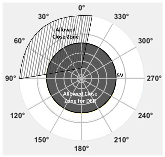
Figure 3.
NPU reclose logic in the presence of DERs based on the differential voltage across the NPU’s breaker.
2.3. Communication-Assisted NPU Logic
To enhance the reliability and sensitivity of the NPU, the DTT or reclose signals from upstream relays on the primary network can be used to accurately differentiate between fault and non-fault conditions. In the communication-assisted approach, the NPU primarily relies on the DTT or reclose signal received from the upstream primary feeder relay to determine the presence of faults on the primary feeder, but maintains aspects of conventional local protection logic to prevent damage in certain scenarios. For instance, if the transfer trip or reclose signal from the upstream relay is absent, the NPU’s conventional local protection logic may still enable the NPU to operate [10]. When DERs are present in the LV network, the NPU’s local trip logic can use desensitized settings set above the secondary transformer’s current rating, allowing for reverse power flow due to DERs, yet preventing damage from high fault current scenarios [10]. Although the NPU’s higher pickup values prevent tripping for high-impedance ground faults, it still retains the protection for phase faults that produce significant reverse fault currents. On the other hand, the NPU’s conventional local reclose logic should be based on the characteristic shown in Figure 3. In the absence of DERs in the LV network, the NPU’s conventional local trip and reclose logic would be utilized, providing an additional layer of protection redundancy.
3. Vulnerabilities of Communication-Assisted NPU Logic
The communication-assisted scheme requires a communication network to transmit the trip and reclose commands from the substation relay to the individual NPUs. This exposes the protection scheme to some vulnerabilities caused by cyberattacks. Herein, DOS attacks to overwhelm the substation relay or NPUs or packet modification attacks to corrupt the trip or reclose commands sent to NPUs are studied.
3.1. Packet Modification Attack
A packet modification attack can take control of the transmitted signal to NPUs and deliver a corrupted value. For example, assume that there is a fault in the primary system and the DTT signal is asserted to 1, but the packet modification attack replaces the asserted DTT signal with 0. In this case, the NPU would not be aware of the fault in the primary system. Similarly, when the substation relay sends a reclose signal to NPUs to connect, the packet modification attack can invert the reclose signal to force NPUs to stay disconnected.
3.2. DOS Attacks
This paper examines two types of DOS attack, i.e., Transmission Control Protocol Synchronization (TCP SYN) and IP fragmentation, which can overwhelm NPUs or substation relays and endanger their proper operation. DOS IP fragmentation is an attack aimed at exhausting a target’s resources and disrupting services by sending packets in fragments, usually close to the maximum transmission unit (MTU) size. This attack forces the packets to wait in the buffer until fully reassembled, leading to an overload on the target’s CPU buffer memory and, in severe cases, resulting in a system crash. A TCP SYN attack takes advantage of the handshake process in a TCP connection (See Figure 4). The attacker begins by sending a large number of SYN packets to the target server, which then responds to each request and opens a port to await the client’s acknowledgment (ACK) packet—an ACK that never arrives. The attacker continues sending SYN packets, causing the server to keep allocating new open ports temporarily. Eventually, this exhausts the server’s available ports, leading to server malfunction. In DOS attacks, the transmission of trip and reclose signals from the SEL 751 relay is disrupted, causing NPUs to lose visibility of primary system faults if they only rely on the communication-assisted protection logic.
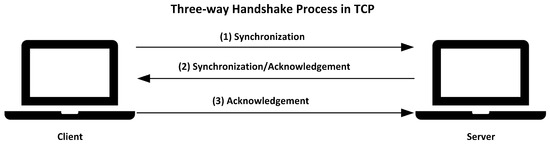
Figure 4.
TCP synchronization attack. The attacker begins by sending a large number of synchronization packets to the target server. The server then responds to each request and opens a port to await the client’s acknowledgment packet, which never arrives.
4. HIL Testbed for the Co-Emulation of Power System and Communication Network
The HIL testbed utilizes the Opal-RT real-time digital simulator, which facilitates the co-simulation of power and cyber systems by the effective integration of EXata-CPS as a communication network emulator to the power system models created in HYPERSIM [19]. The EXata-CPS network communication emulator and cyberattack toolbox by Keysight [20] can be used for the real-time simulation of large-scale and high-fidelity communication network and cyber systems. This tool utilizes a network digital twin to model entire communication networks, various protocol layers, application and physical layers, and devices. EXata-CPS is equipped with a synchronization tool for online and real-time connection to external equipment.
The single line diagram of the secondary network that is modeled in HYPERSIM is shown in Figure 1. The specifications of this system are provided in Table 1. This testbed features a 13.8 kV primary feeder supporting two LV spot networks, simulated in HYPERSIM and run in real-time on an Opal-RT digital simulator. Each primary feeder is protected by an SEL 751 relay equipped with overcurrent protection. The primary feeders comprise two segments: one 2 km segment from the substation to the first LV network and another 1 km segment between the two LV networks. The SEL 751 relay on the top feeder (Feeder 1) can trip the CB1 circuit breaker and sends a DTT or reclose signal to NPU2 and NPU4, while the SEL 751 relay on the bottom feeder can trip the CB2 circuit breaker and sends a DTT or reclose signal to NPU1 and NPU3. Although Modbus TCP/IP could facilitate communication between SEL 751 relays and NPUs, SEL 751’s limited port capabilities require that the DTT signals first be sent to HYPERSIM, which then relays them to the NPUs. Real-time measurements are obtained by SEL 751 relays from Opal-RT through its Analog Output card, connected to the SEL 751’s J2 connector, with HYPERSIM currents downscaled by a factor of 0.00011 to protect the J2 connector. A CT ratio of 337 is set in the relay to accurately read currents. Both relays share identical settings, with instantaneous phase overcurrent pickup set to 5 A in secondary Amps and ground overcurrent pickup set to 2 A, in accordance with IEEE C37.108 standards for primary feeder fault protection [4]. The SEL 751 relay sends a trip signal to its Digital Output card, which is hardwired to Opal-RT’s Digital Input card to operate the simulated breakers during faults. Each NPU operates on a Raspberry Pi (RP) microprocessor and communicates with Opal-RT via Modbus TCP/IP over Ethernet to read the real-time voltage and current phasors and send trip commands to open the relevant breaker. It is essential for each primary feeder relay to send DTT signals to all NPUs connected to that feeder to prevent circulating fault currents. For instance, in Figure 1, the SEL 751 relay on the top feeder sends DTT and reclose signals to both NPU2 and NPU4.

Table 1.
Secondary network model parameters.
The HIL testbed, which includes both the power system model in HYPERSIM and communication network model in EXata-CPS, is shown in Figure 5. The EXata-CPS model is a digital twin of the power system model that runs in real-time with the power system model in HYPERSIM and manages the communication network operation and traffic in a synchronized fashion. Each node in the system has an IP address associated to it and incorporates a virtual node modeled in EXata-CPS, including all the RPs (i.e., NPUs) as well as the Opal-RT simulator IP addresses and SEL 751 relays. EXata-CPS technically manages the Modbus communication between all the server/client pairs. EXata-CPS will be utilized in the next section to apply DOS and packet modification attacks.
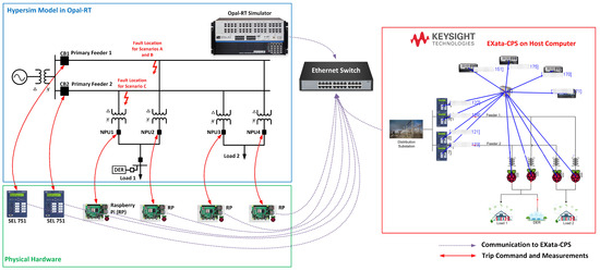
Figure 5.
The HIL testbed.
5. Experimental Results
The impact of cyberattacks on the communication-assisted NPUs was evaluated using the following test scenarios:
Scenario A: Packet modification attack on DTT and reclose signals:
- Scenario A1: No fault, no cyberattack.
- Scenario A2: No fault, with packet modification attack.
- Scenario A3: With Single Line to Ground (SLG) fault, no cyberattack.
- Scenario A4: With SLG fault, with packet modification attack.
- Scenario A5: With Three Phase (3PH) fault, no cyberattack.
- Scenario A6: With 3PH fault, with packet modification attack.
Scenario B: DOS attack:
- Scenario B1: IP fragmentation attack.
- Scenario B2: TCP SYN attack.
Scenario C: Multiple attack scenario.
5.1. HIL Test Results for Packet Modification Attack on DTT Signal
To implement the packet modification attack, EXata-CPS corrupts the DTT and reclose signals by inverting their values (i.e., replacing 1 with 0 or replacing 0 with 1). In the following studies, the conventional local protection logic and communication-assisted logic were both in service on NPUs. For NPU1 and NPU2, the desensitized pickup value was used for the local protection logic due to the presence of DERs. The desensitized pickup was set to 720 A (1.2 pu of the transformer rating) as suggested in [10]. For NPU3 and NPU4, the sensitive trip element’s pickup was equal to 2 A. The insensitive trip pickup was equal to 80 A. The NPU’s characteristic angles were set to 30 and 85 degrees. The delay of the insensitive element was five cycles while the delay of sensitive trip element was 10 s.
5.1.1. Scenario A1: No Fault, No Cyberattack
This scenario represents the normal operation of the system without any faults or cyberattacks in the system. Figure 6 illustrates the NPU RMS currents on the secondary side of their transformers.
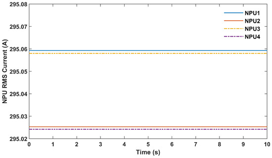
Figure 6.
NPUs’ RMS currents in Scenario A1.
5.1.2. Scenario A2: No Fault, with Packet Modification Attack
In this scenario, since there was no fault in the system, no DTT signal was issued by the SEL 751 relays at the substation. However, it was assumed that the attacker applied a packet modification attack on the DTT signal sent to NPU2. By doing so, the DTT signal sent to NPU2 was asserted. NPU2, which relies on the DTT signal to operate, mistakenly tripped the breaker of its service transformer, resulting in the outage of one of the service transformers. As seen in Figure 7, the NPU2’s RMS current went to zero while the NPU1’s current was almost doubled to support the load after the NPU2’s transformer outage. The DTT, NPU2, and NPU4 trip signals are shown in Figure 8a.
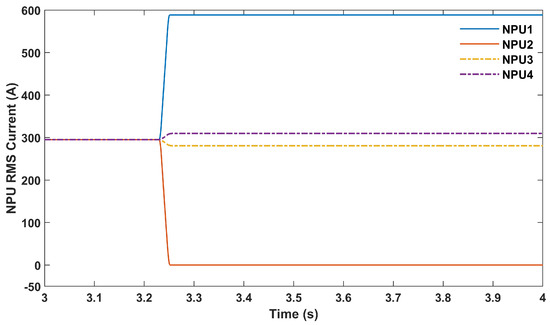
Figure 7.
NPUs’ RMS currents in Scenario A2.
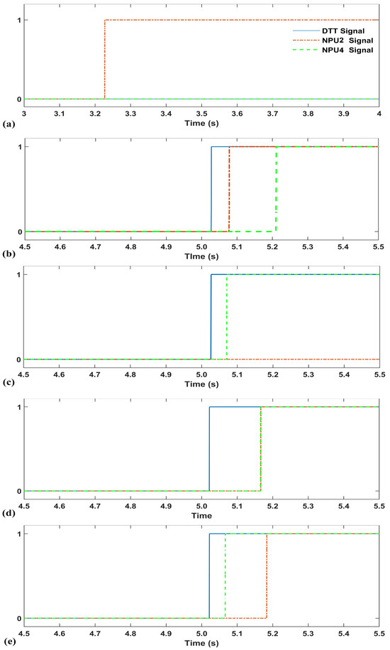
Figure 8.
DTT, NPU2, and NPU4 trip signals in Scenario (a) A2, (b) A3, (c) A4, (d) A5, and (e) A6.
5.1.3. Scenario A3: With SLG Fault, No Cyberattack
In this scenario, an SLG fault was applied on the top primary feeder (Feeder 1) of the system shown in Figure 5. The DTT signal was issued by the SEL 751 relay at the substation. However, there was no attack on the communication system. For this scenario, the NPUs’ RMS currents are shown in Figure 9. The DTT, NPU2, and NPU4 trip signals are shown in Figure 8b.
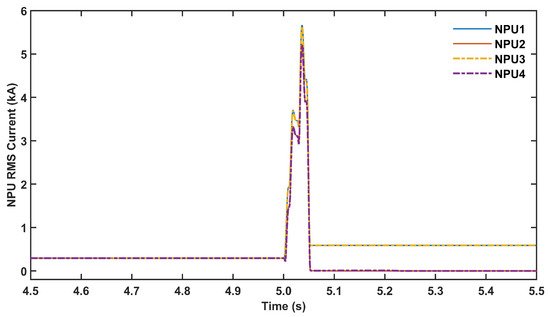
Figure 9.
NPUs’ RMS currents in Scenario A3.
5.1.4. Scenario A4: With SLG Fault, with Packet Modification Attack
In this scenario, an SLG fault was applied on the top primary feeder of the system shown in Figure 5. The DTT signal was issued by the SEL 751 relay at the substation. The packet modification attack was applied on the DTT and reclose signals sent to NPU2. The DTT, NPU2, and NPU4 trip signals are shown in Figure 8c. As can be seen, because of the attack, NPU2 received 0 on the DTT signal and did not trip accordingly. It is recommended that NPUs have their local protection logic as a back up of the DTT scheme. However, the conventional local protection logic of NPUs failed to detect the SLG faults when the service transformer had a delta winding on the primary system side. Because of this issue, the conventional local protection logic of the NPU was not even able to detect the SLG fault and NPU2 never tripped.
In a similar test, it was assumed that the packet modification attack was applied after NPU2 tripped, meaning that while the SLG fault still existed, the attacker deasserted the DTT signal to 0 and asserted the reclose signal to 1. Without any conventional local trip and reclose logic, as discussed in Section 3, NPU2 would reclose its breaker on an active fault; however, the back up reclose logic on NPU2 prevented NPU2 from reclosing its breaker.
5.1.5. Scenario A5: With 3PH Fault, No Cyberattack
In this scenario, a 3PH fault was applied on the top primary feeder of the system shown in Figure 5. The DTT signal was issued by the SEL 751 relay at the substation. However, there was no attack on the communication system. For this scenario, the NPUs’ RMS currents are shown in Figure 10. The DTT, NPU2, and NPU4 trip signals are shown in Figure 8d.
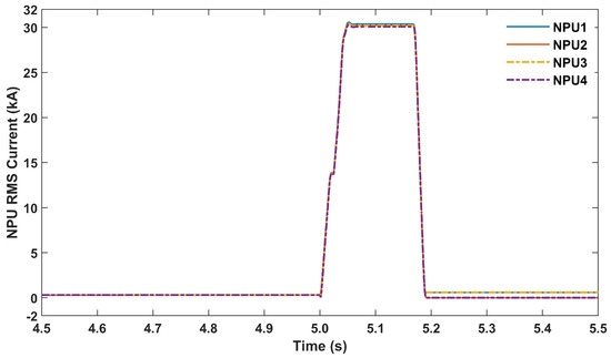
Figure 10.
NPUs’ RMS currents in Scenario A5.
5.1.6. Scenario A6: With 3PH Fault, with Packet Modification Attack
In this scenario, a 3PH fault was applied on the top primary feeder of the system shown in Figure 5. The DTT signal was issued by the SEL 751 relay at the substation. A packet modification attack was applied on the DTT signal sent to NPU2. The DTT, NPU2, and NPU4 trip signals are shown in Figure 8e. As can be seen, even though the packet modification attack impacted the DTT signal, the conventional local protection logic of the NPU acted as a backup and detected the 3PH fault on the primary feeder. Therefore, NPU2 successfully tripped. This shows that for 3PH faults on the primary feeder, the packet modification attacks on the DTT signal are not effective.
In a similar test, it was assumed that the packet modification attack was applied after NPU2 tripped, meaning that while the 3PH fault still existed, the attacker deasserted the DTT signal to 0 and asserted the reclose signal to 1. Without the conventional local trip and reclose logic discussed in Section 3, NPU2 would reclose its breaker on an active fault; however, the back up reclosed logic on NPU2 prevented NPU2 from reclosing its breaker.
5.2. HIL Test Results for DOS Attack
In the following, the impact of DOS attacks on the performance of the DTT scheme is discussed, where the results are only provided for two general types of DOS attacks, i.e., IP fragmentation and TCP SYN attacks. In the following studies, the conventional local protection logic for NPUs was not in service.
5.2.1. Scenario B1: IP Fragmentation Attack Results
Herein, it is assumed that an SLG fault was applied on the top primary feeder. However, NPU2 was the victim of an IP fragmentation attack. As seen in Figure 11, the NPU terminals on MobaXterm show that after the attack, NPU2’s Modbus communication failed. In the modeled attack, the resource failure mode of the attacked node was set to shutdown, meaning that the node could not send or receive packets for the remaining duration of the simulation. In Figure 12a, it is shown that even though there was a fault in the primary feeder, NPU2 did not trip.
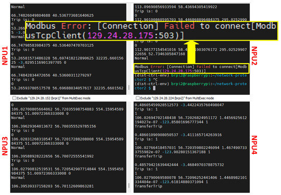
Figure 11.
MobaXterm terminal showing that NPU2’s Modbus’s communication failed after the IP fragmentation attack in Scenario B1.
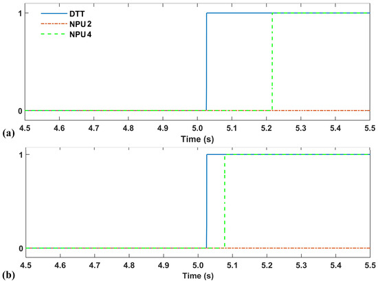
Figure 12.
DTT, NPU2, and NPU4 trip signals in Scenario (a) B1 and (b) B2.
5.2.2. Scenario B2: TCP SYN Attack Results
Herein, it is assumed that an SLG fault was applied on the top primary feeder. However, the server (i.e., SEL 751 relay with the IP address ending in *.122 in HYPERSIM) was the victim of a TCP SYN attack when it tried to send a DTT signal to NPU2. As seen in Figure 13, the traffic monitored by Wireshark shows that TCP Retransmission error after the attack was applied. TCP Retransmission occurs when an acknowledgment of a transmitted packet is not received by the sender within a specific time frame. In Figure 12b, it is shown that even though there was a fault in the primary feeder, NPU2 did not trip. The reason is that the *.122 IP address in HYPERSIM was shutdown, which stopped the transmission of the DTT signal to NPU2.
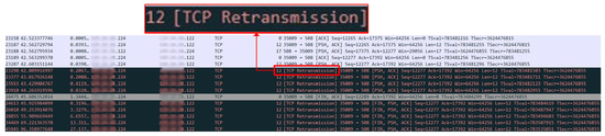
Figure 13.
The traffic monitored by Wireshark on the DTT signal sent to NPU2 in Scenario B2. TCP Retransmission occurs when an acknowledgment of a transmitted packet is not received by the sender within a specific time frame.
5.3. Scenario C: Multiple Attack Scenario
In this scenario, it is assumed that an SLG fault was applied on the primary feeder (Feeder 2) in Figure 1. It was also assumed that the conventional local protection logic and communication-assisted logic were both in service on NPUs. After this fault occurred, the SEL 751 relay at CB2 detected the fault and opened CB2. It also sent the DTT signal to NPU1 and NPU3. However, it was assumed that a multiple attack scenario corrupted the DTT signals sent to NPU1, NPU3, and NPU4. It was assumed that the DER was in service but not generating (e.g., a PV system during night time). Packet modification attacks were applied at the same time to change the DTT signal sent to NPU1 and NPU3 to 0 and the DTT signal sent to NPU4 to 1. Because of this attack, NPU1 and NPU3 did not open their corresponding breakers and NPU4 mistakenly opened its breaker. The NPUs’ RMS currents are shown in Figure 14. As can be seen, before 4.7 s, the attacker applied the three packet modification attacks on the DTT signals transmitted to NPU1, NPU3, and NPU4. Because of these attacks, NPU4 disconnected its service transformer and its current dropped to zero while the whole Load 2 was supported by NPU3’s transformer. At 5 s, an SLG fault was applied. Herein, it was assumed that the NPUs were not equipped with the conventional local protection and only relied on the DTT signal for identifying a fault. As seen in Figure 14, after the fault happened, NPU1 and NPU3 did not send a trip command to their transformers because they received the corrupted DTT signal from CB2’s SEL 751 relay. On the other hand, NPU4 also kept its service transformer out of service because of the corrupted DTT signal it was receiving. This forced NPU2 to carry Load 1 and Load 2 together, meaning that its current reached to more than 1160 A. This current is way more than the nominal rating of this service transformer and would definitely cause damage. This scenario shows the importance of using local protection at NPUs in addition to the communication-assisted scheme.
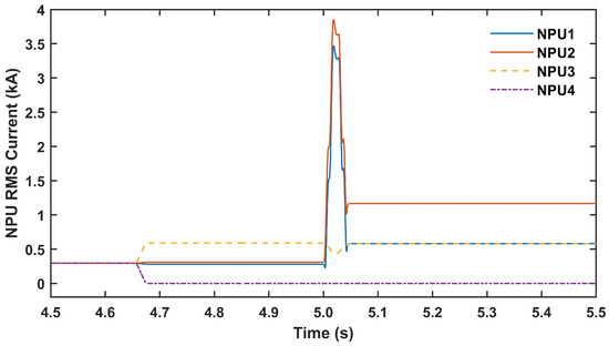
Figure 14.
NPUs’ RMS currents in Scenario C.
For a three-phase fault, the local protection of NPU1 would have tripped even after the SEL 751 at CB2 tripped. However, for the SLG fault, after the SEL 751 at CB2 tripped, NPU1’s local protection would not have tripped because NPU1 would experience around 580 A of the reverse current to support Load 2. This is below the desensitized setting of NPU1 (i.e., 720 A in the presence of DERs).
6. Conclusions and Summary of Observations
This paper evaluated the cyber security of NPUs in the presence of communication-assisted scheme. The paper investigated the impact of DOS and packet modification attacks on the communication-assisted protection logic of NPUs using a HIL testbed that includes both real-time power system and communication network digital simulators. A summary of the observed impacts of cyberattacks is provided in Table 2.
Table 2.
Summary of impact of cyberattacks on communication-assisted scheme for NPUs.
Recommendations to Improve the Reliability of the Communication-Assisted NPU Protection
In the following, a list of recommendations is provided:
- As an important mitigative action to reduce the impact of cyberattacks, it is recommended that NPUs utilize conventional local trip and reclose logic algorithms in addition to the communication-assisted logic to ensure a reliable operation if the communication-assisted logic is compromised by a cyberattack. Accommodating the conventional local protection logic in the NPU will significantly help with the continuous operation of the NPU under loss of communication. However, the settings of the trip and reclose logic should be desensitized to accommodate the DER presence.
- For the SLG faults, under some circumstances, the conventional local trip logic may fail to detect these faults, which prevents the operation of the NPU if the DTT signal from the upstream protection relay is lost or corrupted. The fault currents going through NPUs under an SLG fault when the service transformer has a delta winding on the primary system side are minimal, resulting in no damage to the equipment.
- Since NPUs prioritize the DTT signal over the conventional local trip logic, when there is no fault in the primary system, the packet modification attack results in false tripping of the NPU’s breaker. In this case, since one of the service transformers in a spot network is down, the other service transformer carries the whole load. The rating of service transformers in spot networks should be based on the total load in that spot network, so the packet modification attack in this case does not overload the active service transformer.
- The packet modification attack can also try to deceive the NPU to reclose on a live fault by corrupting the reclose signal. However, the conventional local reclose logic can act effectively and avoid the reclosure of the NPU’s breaker.
- In some cases, by overwhelming the target, the DOS attack may exhaust critical resources such as CPU, memory, and the network bandwidth. Under these circumstances, the DOS attack’s impact can be more critical than the packet modification attack in which the whole NPU’s CPU and memory can be exhausted, which also renders the local conventional trip and reclose logic algorithms ineffective. Under these circumstances, the following actions are suggested as mitigative and preventive measures: (i) The redundancy of the critical resources will significantly help with the mitigation of the impact of the DOS attack. (ii) The attack surface should be reduced by closing unused ports on relays and NPUs, segmenting networks, and implementing strong access control lists. (iii) The bandwidth should be increased to ensure sufficient bandwidth and server resources to absorb traffic surges during an attack. (iv) Rate limiting should be used to restrict the number of requests from a single source within a specific timeframe, preventing attackers from overwhelming resources. (v) The network traffic should be monitored for suspicious patterns and automatically block malicious activity.
Author Contributions
Conceptualization, M.S., A.B., M.J.R. and J.A.A.; Methodology, M.J., M.S., A.B., M.J.R. and J.A.A.; Software, M.J. and M.S.; Validation, M.J. and M.S.; Formal analysis, M.J. and A.B.; Investigation, M.J. and A.B.; Writing—original draft, M.J., A.B., M.J.R. and J.A.A.; Supervision, A.B. and M.J.R.; Funding acquisition, A.B. and M.J.R. All authors have read and agreed to the published version of the manuscript.
Funding
This material is based upon work supported by the Sandia National Laboratories’ Laboratory Directed R&D (LDRD) 24-0759 funding and National Science Foundation under awards #ECCS 2338555 and #OISE 2330582. This article has been authored by an employee of National Technology & Engineering Solutions of Sandia, LLC under Contract No. DE-NA0003525 with the U.S. Department of Energy (DOE).
Data Availability Statement
Dataset available on request from the authors.
Acknowledgments
The employee owns all right, title and interest in and to the article and is solely responsible for its contents. The United States Government retains and the publisher, by accepting the article for publication, acknowledges that the United States Government retains a non-exclusive, paid-up, irrevocable, world-wide license to publish or reproduce the published form of this article or allow others to do so, for United States Government purposes. The DOE will provide public access to these results of federally sponsored research in accordance with the DOE Public Access Plan https://www.energy.gov/downloads/doe-public-access-plan, accessed on 3 June 2025.
Conflicts of Interest
The authors declare no conflicts of interest.
Abbreviations
The following abbreviations are used in this manuscript:
| NPUs | Network Protector Units |
| HIL | Hardware In the Loop |
| DERs | Distributed Energy Resources |
| DTT | Direct Transfer Trip |
| IEDs | Intelligent Electronic Devices |
| DOS | Denial-of-Service |
| TCP SYN | Transmission Control Protocol Synchronization |
| MTU | Maximum Transmission Unit |
| RP | Raspberry Pi |
References
- Hincapie I., R.A.; Gallego R., R.A.; Mantovani, J.R. A decomposition approach for integrated planning of primary and secondary distribution networks considering distributed generation. Int. J. Electr. Power Energy Syst. 2019, 106, 146–157. [Google Scholar] [CrossRef]
- Montano-Martinez, K.; Thakar, S.; Ma, S.; Soltani, Z.; Vittal, V.; Khorsand, M.; Ayyanar, R.; Rojas, C. Detailed primary and secondary distribution system model enhancement using AMI data. IEEE Open Access J. Power Energy 2021, 9, 2–15. [Google Scholar] [CrossRef]
- IEEE Std 1547.6-2011; Recommended Practice for Interconnecting Distributed Resources with Electric Power Systems Distribution Secondary Networks. IEEE: Piscataway, NJ, USA, 2011.
- IEEEC37.108-2021; Guide for Protection of Secondary Network Systems. IEEE: Piscataway, NJ, USA, 2021.
- Ropp, M.E.; Reno, M.J.; Bower, W.; Reilly, J.; Venkata, S. Secondary Networks and Protection: Implications for der and Microgrid Interconnection; Technical Report; Sandia National Lab.(SNL-NM): Albuquerque, NM, USA, 2020.
- IEEEC57.12.44-2014; Standard Requirements for Secondary Network Protectors. IEEE: Piscataway, NJ, USA, 2014.
- Smith, D.R.; Faulkner, M.A. Network Protector Control for Spot Network Fed from Feeder Sources Having Voltage Differences. US Patent 10,096,991, 9 October 2018. [Google Scholar]
- Mohammadi, P.; Mehraeen, S. Challenges of PV integration in low-voltage secondary networks. IEEE Trans. Power Deliv. 2016, 32, 525–535. [Google Scholar] [CrossRef]
- Cheng, Z.; Udren, E.; Holbach, J.; Reno, M.J.; Ropp, M.E. Protection and Control Challenges of Low-Voltage Networks with High Distributed Energy Resources Penetration-Part 1: Utility Workshop and Low-Voltage Network Modeling. In Proceedings of the 2023 76th Annual Conference for Protective Relay Engineers (CFPR), College Station, TX, USA, 27–30 March 2023; IEEE: Piscataway, NJ, USA, 2023; pp. 1–15. [Google Scholar]
- Azzolini, J.A.; Ropp, M.E.; Reno, M.J. Options for Upgrading Low-Voltage Spot Network Protection to Increase DER Interconnection Capacity; Technical Report; Sandia National Lab.(SNL-NM): Albuquerque, NM, USA, 2024.
- Joshi, M.; Snow, M.; Bidram, A.; Reno, M.J.; Ropp, M.; Azzolini, J.A. Hardware-in-the-Loop Testing of Direct Transfer Trip for Network Protector Units in the Presence of Distributed Energy Resources. In Proceedings of the 2024 56th North American Power Symposium (NAPS), El Paso, TX, USA, 13–15 October 2024; IEEE: Piscataway, NJ, USA, 2024; pp. 1–6. [Google Scholar]
- SEHGAL-SIDHU, P.; APUZZO, M. Integrating Distributed Energy Resources into ENMAX’s Secondary Network System. In Proceedings of the 2022 CIGRE Canada Conference & Expo, Calgary, AB, Canada, 31 October–2 November 2022; CIGRE: Paris, France, 2022; pp. 1–9. [Google Scholar]
- Huseinović, A.; Mrdović, S.; Bicakci, K.; Uludag, S. A survey of denial-of-service attacks and solutions in the smart grid. IEEE Access 2020, 8, 177447–177470. [Google Scholar] [CrossRef]
- Ortega-Fernandez, I.; Liberati, F. A review of denial of service attack and mitigation in the smart grid using reinforcement learning. Energies 2023, 16, 635. [Google Scholar] [CrossRef]
- Hussain, S.; Iqbal, A.; Hussain, S.S.; Zanero, S.; Shikfa, A.; Ragaini, E.; Khan, I.; Alammari, R. A novel hybrid methodology to secure GOOSE messages against cyberattacks in smart grids. Sci. Rep. 2023, 13, 1857. [Google Scholar] [CrossRef] [PubMed]
- Takiddin, A.; Atat, R.; Ismail, M.; Boyaci, O.; Davis, K.R.; Serpedin, E. Generalized graph neural network-based detection of false data injection attacks in smart grids. IEEE Trans. Emerg. Top. Comput. Intell. 2023, 7, 618–630. [Google Scholar] [CrossRef]
- Mahmood, H.; Mahmood, D.; Shaheen, Q.; Akhtar, R.; Changda, W. S-DPs: An SDN-Based DDoS Protection System for Smart Grids. Secur. Commun. Netw. 2021, 2021, 6629098. [Google Scholar] [CrossRef]
- Alyami, S.; Alharbi, R.; Azzedin, F. Fragmentation attacks and countermeasures on 6LoWPAN Internet of Things networks: Survey and simulation. Sensors 2022, 22, 9825. [Google Scholar] [CrossRef] [PubMed]
- Opal-RT. Cyber-Physical Simulation Testbed for Power Systems; Opal-RT: Montreal, QC, Canada, 2025. [Google Scholar]
- Keysight. EXata Network Modeling—Critical Infrastructure; Keysight: Singapore, 2025. [Google Scholar]
Disclaimer/Publisher’s Note: The statements, opinions and data contained in all publications are solely those of the individual author(s) and contributor(s) and not of MDPI and/or the editor(s). MDPI and/or the editor(s) disclaim responsibility for any injury to people or property resulting from any ideas, methods, instructions or products referred to in the content. |
© 2025 by the authors. Licensee MDPI, Basel, Switzerland. This article is an open access article distributed under the terms and conditions of the Creative Commons Attribution (CC BY) license (https://creativecommons.org/licenses/by/4.0/).