Review

Line-Start Permanent Magnet Synchronous Motors: Evolution, Challenges, and Industrial Prospects

Department of Electrical Engineering, Faculty of Engineering, University of Malta, Msida Campus (Main Campus), MSD 2080 Msida, Malta
*
Authors to whom correspondence should be addressed.
Energies 2025, 18(17), 4545; https://doi.org/10.3390/en18174545
Submission received: 23 June 2025 / Revised: 17 July 2025 / Accepted: 22 August 2025 / Published: 27 August 2025

Abstract

Line-Start Permanent Magnet Synchronous Motors (LSPMSMs) offer a hybrid solution that combines the high efficiency of permanent magnet motors with the self-starting capability of induction machines. This review examines their key performance characteristics, historical development, and design approaches. Advantages such as high efficiency, improved power factor, and operational stability are discussed alongside challenges like limited critical inertia and synchronization issues. Design enhancements through rotor topology optimization and cage resistance adjustment are also explored. Finally, market trends and economic considerations are evaluated, highlighting the strong potential of LSPMSMs in energy-efficient motor applications.

1. Introduction

Electric motors account for more than 53% of global electricity consumption, powering diverse applications ranging from industrial machinery and transportation systems to household appliances [1,2]. The three-phase squirrel-cage Induction Motor (IM) dominates the market due to its robustness and simplicity, particularly in fixed-speed applications, such as pumps, compressors, and fans. However, this motor is not the most energy-efficient choice [3].
One promising solution is the Line-Start Permanent Magnet Synchronous Motor (LSPMSM)—a hybrid technology that merges the high efficiency and high power density of Permanent Magnet (PM) motors with the Direct-On-Line (DOL) starting capability of conventional induction machines. This allows for synchronous operation without the need for complex control systems or Variable Frequency Drives (VFDs). The performance of LSPMSMs is heavily influenced by the characteristics of the embedded permanent magnets, which play a crucial role in enabling high efficiency and reliable synchronization.
The feasibility of such designs significantly improved with the introduction of high-performance permanent magnet materials, particularly neodymium–iron–boron (NdFeB) magnets, in the 1980s [4]. These materials provided stronger magnetic fields and better thermal stability, which allowed engineers to design more compact, efficient, and reliable LSPMSMs. As a result, interest in this motor type has grown steadily across various sectors and applications [5].
Despite their advantages, LSPMSMs face design and operational challenges. A critical aspect lies in balancing transient performance (start-up torque, synchronization) with steady-state performance (efficiency, power factor) [6]. During startup, the interaction between the rotor’s PM field and the induced currents in the squirrel cage can introduce mechanical stress and electromagnetic disturbances, potentially compromising motor reliability and lifespan.
To overcome these challenges, recent research has employed advanced modeling tools—particularly Finite Element Analysis (FEA)—to better understand and optimize LSPMSM performance under dynamic conditions [7].
This paper presents a comprehensive review of line-start permanent magnet synchronous motors. It covers their historical evolution, design developments, performance bottlenecks, and application trends. The review highlights how LSPMSMs can serve as efficient replacements for traditional induction motors in modern industrial applications, focusing on their efficiency advantages and suitability for fixed-speed operations in contemporary industry.

2. Emissions, Efficiency, and Motor Standards

2.1. Energy Consumption and Climate Impact

Global warming is one of the most pressing environmental challenges today, primarily driven by energy production from fossil fuels. The combustion of coal, oil, and natural gas releases significant amounts of carbon dioxide (CO2) and other greenhouse gases, which, in turn, contribute to the rise in global temperatures.
According to the 2023 Intergovernmental Panel on Climate Change (IPCC) Synthesis Report, immediate and sustained reductions in greenhouse gas emissions are vital to limit global temperature rise to 1.5–2 °C above pre-industrial levels—the critical threshold for preventing catastrophic climate impacts [8].
Fossil fuels have long dominated the global energy landscape, consistently accounting for the majority of the world’s primary energy supply [9]. In 2023, fossil fuels still represented 61% of the global electricity mix, as illustrated in Figure 1 [10]. This ongoing reliance highlights the urgent need to transition toward cleaner energy sources and reduce overall energy consumption to meet international climate goals.

2.2. Electric Motors and Energy Demand

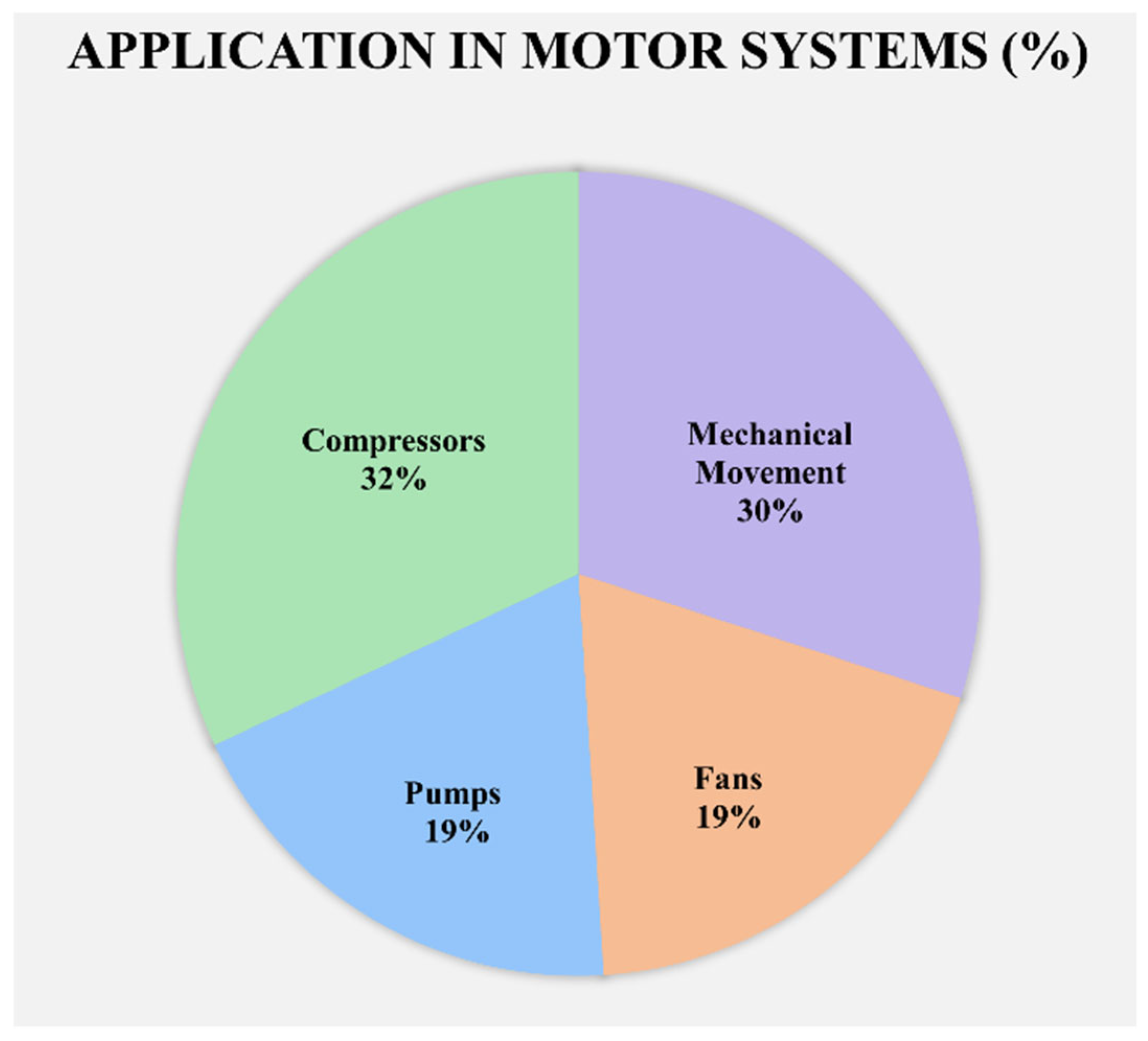
Electric motors consume over 50% of the world’s generated electricity, with a significant portion attributed to fixed-speed applications, such as fans, pumps, and compressors. These systems alone account for nearly 70% of motor-driven electricity use, as illustrated in Figure 2 [11].
Predominantly used in industrial settings, fixed-speed systems present a key area for reducing energy demand. Improving their efficiency through advanced motor technologies provides a practical and cost-effective strategy to lower electricity consumption, reduce operational costs, and support broader climate and sustainability objectives.

2.3. Efficiency Classes for Electric Motors

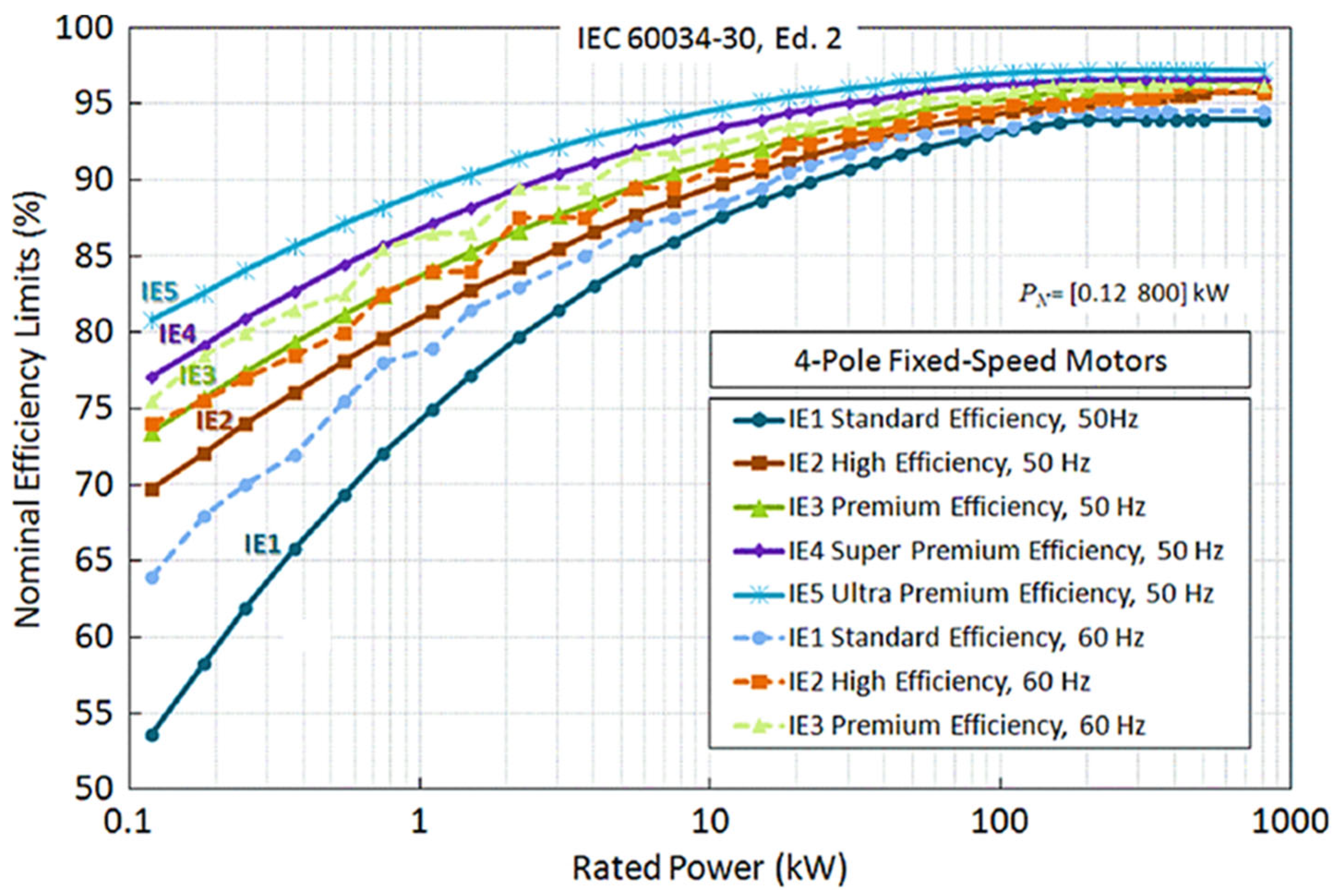
The widespread adoption of energy-efficient motors has become a central strategy for reducing industrial electricity consumption and minimizing greenhouse gas emissions [12]. To provide a harmonized framework for assessing and comparing motor efficiency, the International Electrotechnical Commission (IEC) introduced the IEC 60034-30 standard [13]. This standard defines five distinct efficiency classes for low-voltage, three-phase, single-speed electric motors: IE1 (Standard Efficiency), IE2 (High Efficiency), IE3 (Premium Efficiency), IE4 (Super Premium Efficiency), and IE5 (Ultra Premium Efficiency). These classifications serve as benchmarks for both regulatory compliance and industrial procurement, enabling informed decisions that align with energy policy goals.
Figure 3 illustrates the efficiency levels of these classes across the 0.12–800 kW power range. Based on rated output power and application requirements, motors must meet minimum efficiency thresholds as specified by the IEC framework [14]. Regulatory trends over the past decade reflect a growing commitment to high-efficiency standards. For example, IE3 is now mandated in regions such as the United States, European Union, Japan, and South Korea, while IE2 remains the minimum requirement in countries including India and Australia.
Recent developments highlight an even stronger push toward energy efficiency. As of 1 July 2023, the European Union requires motors with rated outputs between 75 kW and 200 kW to comply with IE4 efficiency standards, demonstrating a global push to reduce motor-related energy losses and accelerate industrial sustainability. While current regulations set the IE4 standard as mandatory for certain motor categories, there is a growing expectation that the EU will continue to advance toward even higher efficiency levels, such as IE5, as part of its broader commitment to energy efficiency and climate goals. Ongoing advancements in motor technology, coupled with increasing political and environmental pressures, suggest that future regulations may incorporate these higher efficiency standards.
Table 1 summarizes the Minimum Energy Performance Standards (MEPS) adopted by various countries, reflecting the global trend toward high-efficiency motor classes, such as IE2 and IE3.

3. Fundamentals of LSPMSMs

3.1. Operating Theory and Equivalent Circuit

A Line-Start Permanent Magnet Synchronous Motor (LSPMSM) integrates a conventional stator, either single-phase or three-phase, with a hybrid rotor that incorporates both a squirrel cage and embedded permanent magnets. At startup, the motor operates similarly to an induction motor, with net torque resulting from the opposing effects of cage-produced torque and the braking torque induced by the permanent magnets. As the rotor accelerates toward synchronous speed, the machine transitions into synchronization. Once synchronized, the rotor is driven primarily by the combined effects of reluctance torque and magnet-based synchronous torque.
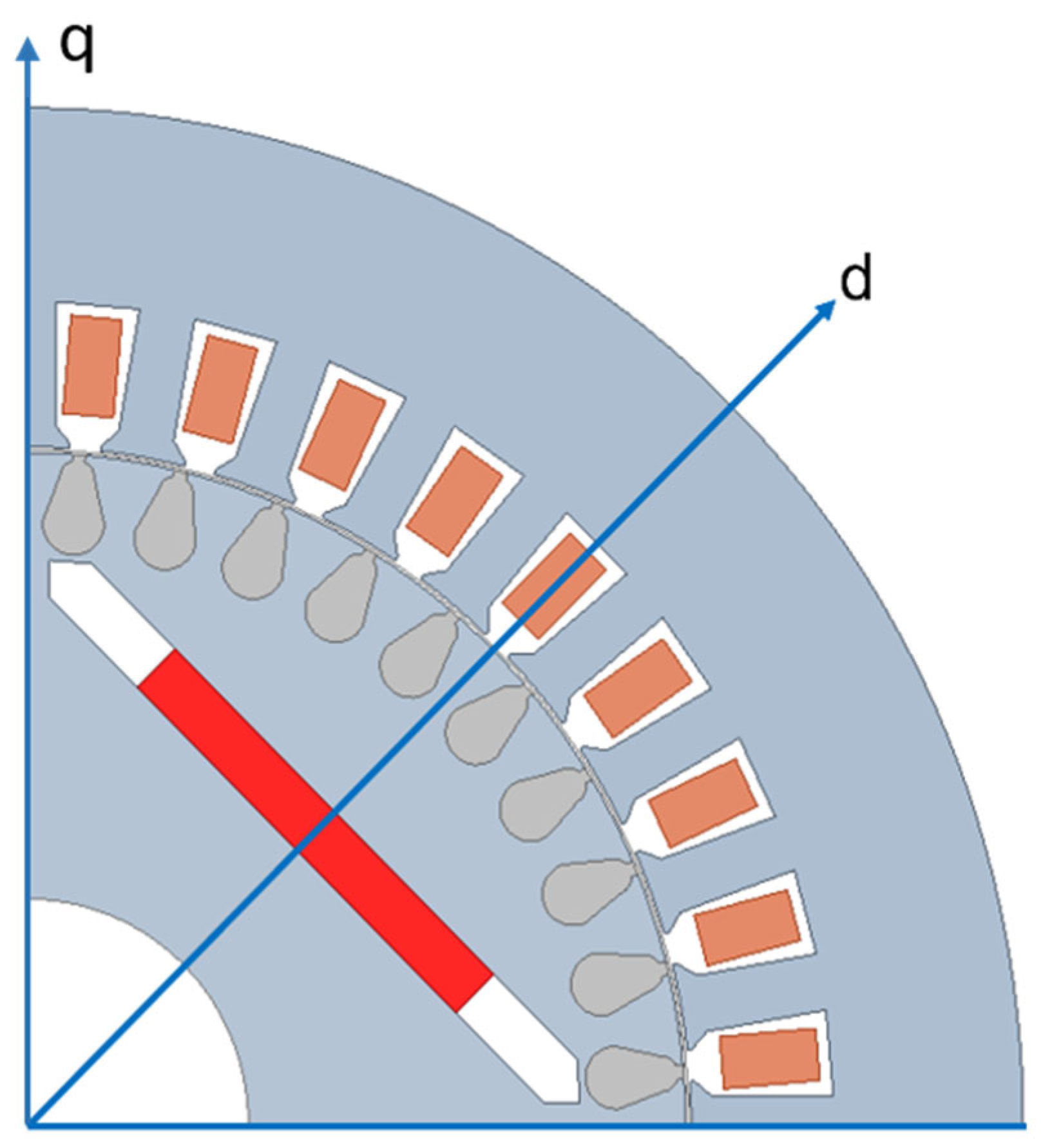
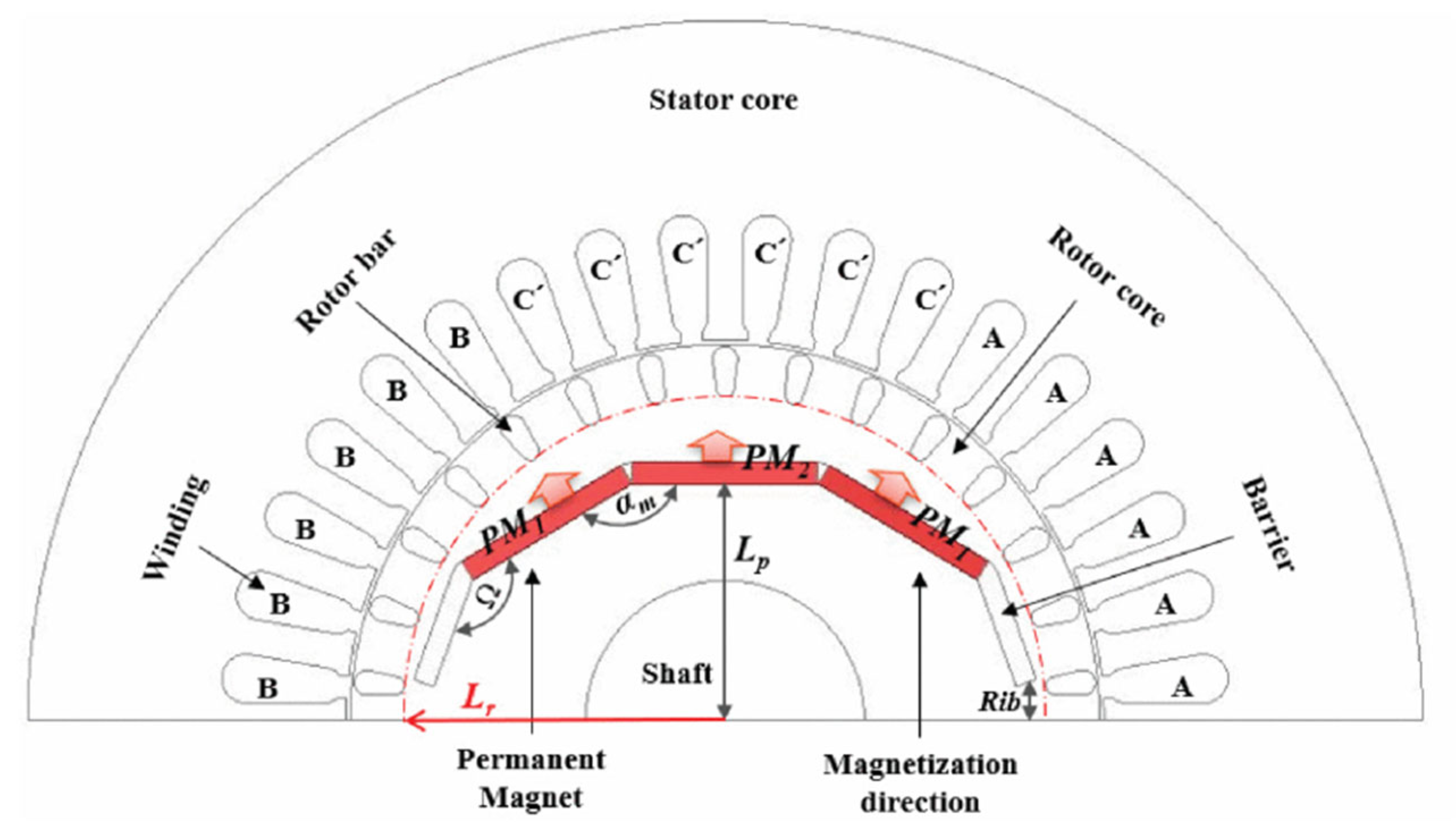
The rotor geometry and the orientation of the direct (d) and quadrature (q) axes are illustrated in Figure 4, where the magnet flux is aligned along the d-axis.
The dynamic behavior of the motor can be modeled using equations expressed in the rotating synchronous d-q reference frame. The associated voltage equations are as follows [17]:
V q s = d λ s q d t + r s i s q + p ω r m λ s d ,
V d s = d λ s d d t + r s i s d p ω r m λ s q ,
V q r = d λ r q d t + r r q i r q = 0 ,
V d r = d λ r d d t + r r d i r d = 0 ,
where V q s , V d s , V q r , and V d r represent the q- and d-axis voltages of the stator and rotor, respectively. The corresponding flux linkages are denoted by λ s q , λ s d , λ r q , and λ r d . The stator and rotor currents in the q–d axes are given by i s q , i s d , i r q , and i r d . The resistances of the stator and rotor are r s , r r q , and r r d , respectively. ω r m denotes the mechanical angular speed of the rotor, and p is the number of pole pairs. The stator and rotor flux linkage expressions are given as follows:
λ s q = L s q i s q + L m q i r q ,
λ s d = L s d i s d + L m d i r d + λ m ,
λ r q = L r q i r q + L m q i s q ,
λ r d = L r d i r d + L m d i s d + λ m ,
where L s q and L s d denote the stator synchronous inductances along the q- and d-axes, respectively. The magnetizing inductances are represented by L m q and L m d . The rotor self-inductances, referred to the stator side, are L r q and L r d . The permanent magnet flux linkage is modeled by λ m .
Figure 5 illustrates the dq-axis equivalent circuit of an LSPMSM.
The expressions for electromagnetic torque are provided as follows [3]:
T e m = 3 P 2 L s d L s q i s d i s q R e l u c t a n c e   T o r q u e + 3 P 2 L m d i r d i s q L m q i r q i s d C a g e   T o r q u e + 3 P 2 λ m i s q M a g n e t T o r q u e   ,
in which the first term is reluctance torque, the second term is cage torque, and the third term is magnet synchronous torque.
The previously presented equation describes instantaneous torque, reflecting the motor’s dynamic behavior. In contrast, the analysis of average torque assumes steady-state operation at each slip point. The derivation of corresponding average expressions is comprehensively detailed in [17]. First, the cage torque component, corresponding to that of a conventional Squirrel-Cage Induction Motor (SCIM), is calculated using the standard equivalent circuit of an IM under steady-state conditions. This torque depends on the slip s , which is the difference between rotor speed and the synchronous speed of the rotating magnetic field as well as on key parameters such as stator and rotor resistance ( r s and r r ), leakage reactance ( X l s , X l r ), and the supply voltage V (rms value). The expression for the average cage torque is given in Equation (10):
T c = 3 p V 2 r r s ω r m r s + r r s 2 + X l s + X l r 2 ,
In addition to the cage torque, the permanent magnets contribute a braking torque, which must be considered during startup. This braking torque is a negative torque component that opposes the rotor’s motion. The phenomenon originates from the relative motion between the stator and rotor magnetic fields during asynchronous operation in Line-Start Permanent Magnet Synchronous Motors (LSPMSMs). At startup, the stator produces a rotating Magnetomotive Force (MMF) at synchronous speed, while the rotor, initially at rest or rotating below synchronous speed, generates its own MMF due to the embedded magnets and rotor saliency. This mismatch in speed causes the rotor’s Magnetomotive Force (MMF), which is stationary in the rotor reference frame, to appear as a rotating field in the stator reference frame at slip frequency. As the rotor accelerates but remains asynchronous, this relative motion induces low-frequency harmonic components in the stator windings. These harmonics interact with the stator’s fundamental MMF and contribute to a braking torque that opposes the rotor’s motion during the startup phase. As the rotor accelerates and approaches synchronous speed, both stator and rotor MMFs begin to rotate at the same frequency. Once synchronization is achieved, the relative motion disappears, the braking torque vanishes, and the magnetic interaction contributes instead to positive synchronous torque through both magnet and reluctance effects. The average braking torque is given by the following:
T b = 3 p 2 ω e r s 2 + ( 1 s ) 2 X s q 2 r s 2 + ( 1 s ) 2 X s d X s q r s E 0 2 ( 1 s ) r s 2 + ( 1 s ) 2 X s d X s q ,
where E 0 denotes the induced back EMF (rms value), X s d and X s q are the stator reactances along the d- and q-axes, respectively, and ω e is the electrical synchronous speed of the motor. The maximum braking torque is given by the following:
T b m a x = 3 p 2 ω e r s 2 1 + X s q X s d 2 r s 2 E 0 2 r s 2 2 r s 2 X s d X s q .
Equations (11) and (12) demonstrate that braking torque depends largely on the saliency ratio ( X s q / X s d ) of the motor and also on the motor back-emf E 0 . That is why a high-saliency PM motor with a large back-emf results in a greater braking torque during starting.
At synchronous speed, the rotor windings experience no variation in flux linkage; consequently, no current flows through the short-circuited cage. If the term p ω r m is replaced by ω e and the time derivatives of all flux linkages are neglected, the expression for synchronous torque can be derived, as presented in Equation (13):
T s ( δ ) = 3 p E 0 V 2 ω e X s d s i n   δ M a g n e t   T o r q u e + 3 p V 2 X s d X s q 4 ω e X s q X s d s i n   2 δ R e l u c t a n c e   T o r q u e ,
Here, V denotes the supply peak voltage, and δ represents the load angle between the supply voltage vector and the no-load back-EMF E 0 .
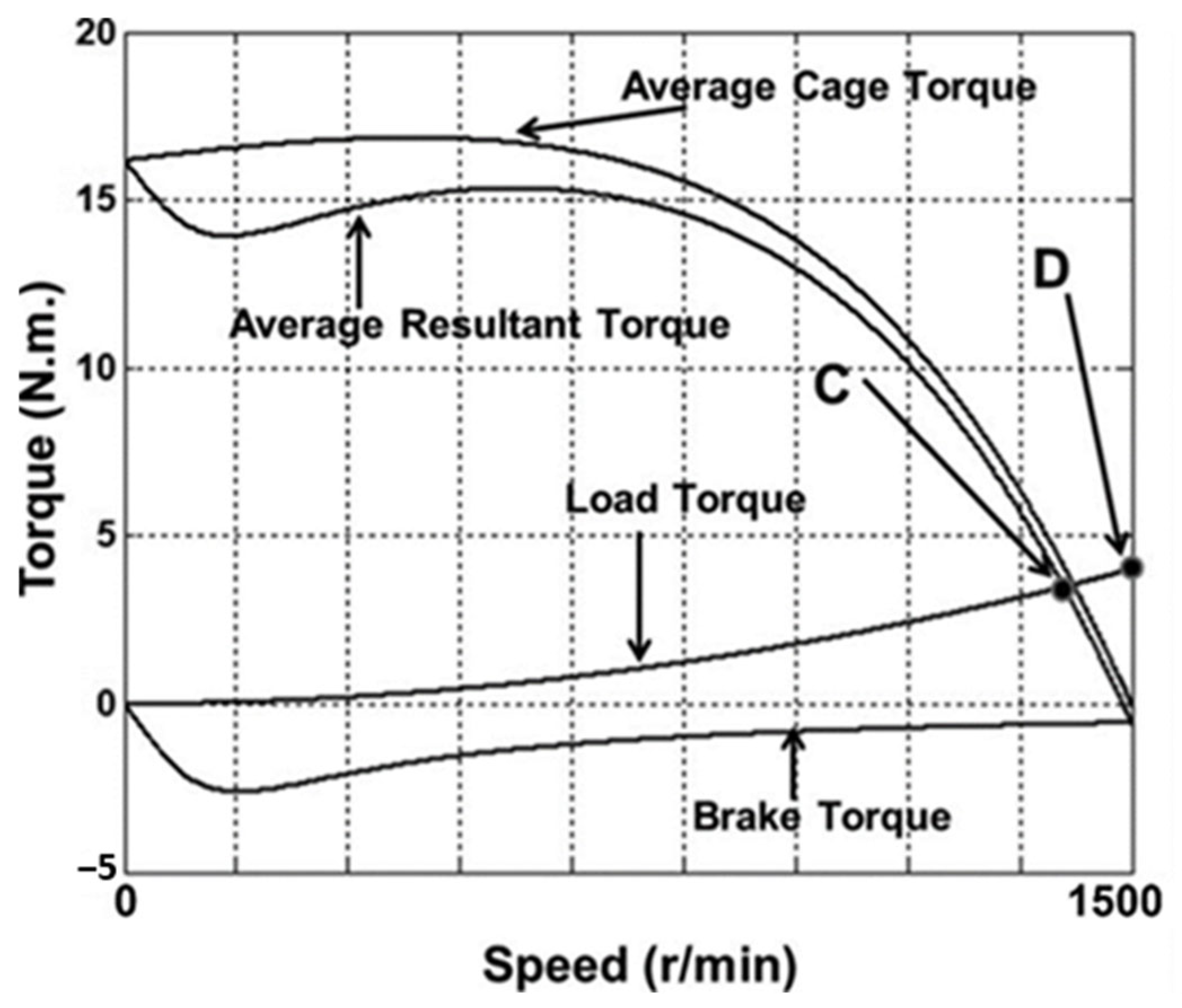
Figure 6 illustrates the torque–speed characteristics of a typical Line-Start Permanent Magnet Synchronous Motor (LSPMSM), highlighting the average cage torque, braking torque, and resultant torque.

3.2. Startup Behavior and Synchronization Issues

The synchronization process in Line-Start Permanent Magnet Synchronous Motors (LSPMSMs) has been extensively studied in the literature, notably by Miller [6] and Rahman et al. [17]. As the motor accelerates from standstill, it initially behaves like an induction motor due to the squirrel-cage rotor. The synchronization phase begins once the rotor approaches synchronous speed and the average asynchronous torque matches the load torque—typically just below synchronism (point C in Figure 6). The subsequent transition to zero slip (point D) defines the critical pull-in phase of synchronization.
The equation of motion governing this transition is as follows:
1 p J ω s 2 s d s d δ = T s δ + T c s T b ( s ) T L ( s ) .
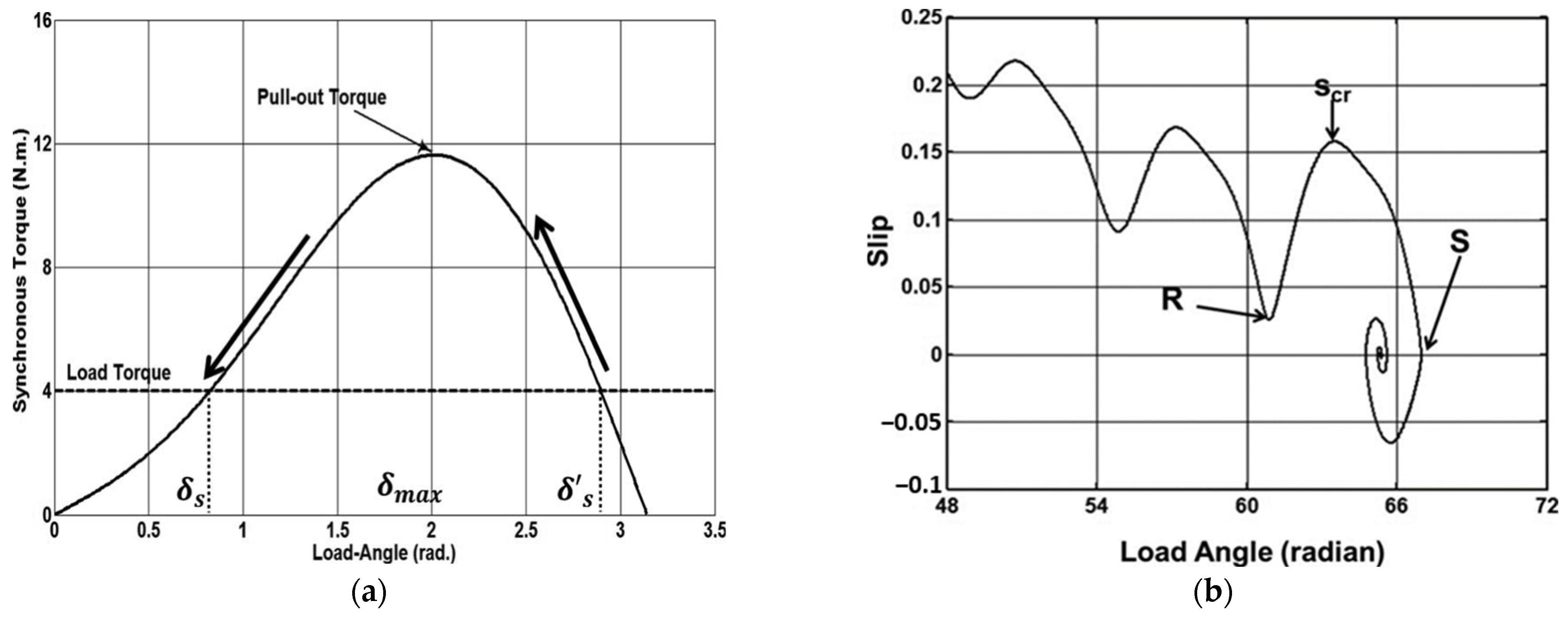
Figure 7a illustrates the torque-load angle characteristic. The electrical load angle δ s marks the first instance where the motor reaches synchronous speed, achieving torque equilibrium. However, due to inertia and damping, the rotor does not settle immediately at δ s . Instead, it overshoots this point, continuing to accelerate momentarily. During this transition, the electromagnetic torque remains greater than the load torque between δ s and δ s , which helps pull the rotor into a new stable position. As a result, the system eventually settles at a steady-state load angle δ s , where torque balance and synchronization are stably maintained.
The variable s c r denotes the critical slip at which the transition to synchronous speed begins, as shown in Figure 7b.
Successful pull-in occurs during the last pole slip from point R to point S spanning approximately 2π electrical radians. At the critical slip s c r , the corresponding torque angle δ c r is given by δ s π .
The energy required to complete this transition is the apparent kinetic energy of the load, represented by the following:
K s c r = s c r 0   1 p J ω s 2 s d s = 1 2 p J s c r 2 ω s 2 ,
On the other side, the pull-in energy K p e [17] is calculated by accounting for all torque contributions—synchronous torque T s ( δ ) , cage torque T c , braking torque T b , and the load torque T l :
K p e = δ s π δ s   T s ( δ ) + T c s T b ( s ) T L ( s ) d δ ,
For successful synchronization, the motor must supply sufficient pull-in energy such that K p e > K s c r . Based on this energy balance, the critical inertia J c r of the motor can be computed using the following expression [17]:
J c r = 2 p K p e s c r 2 w s 2 ,
Here, p denotes the number of pole pairs in the machine, and w s represents the synchronous angular frequency, expressed in radians per second [rad/s].
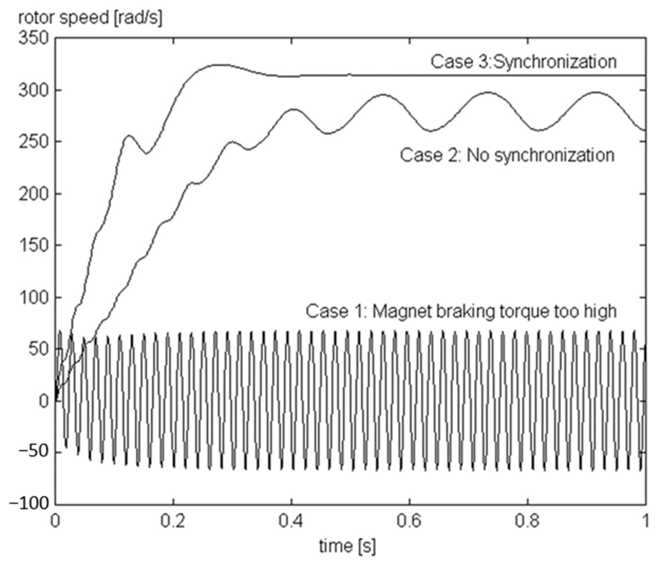
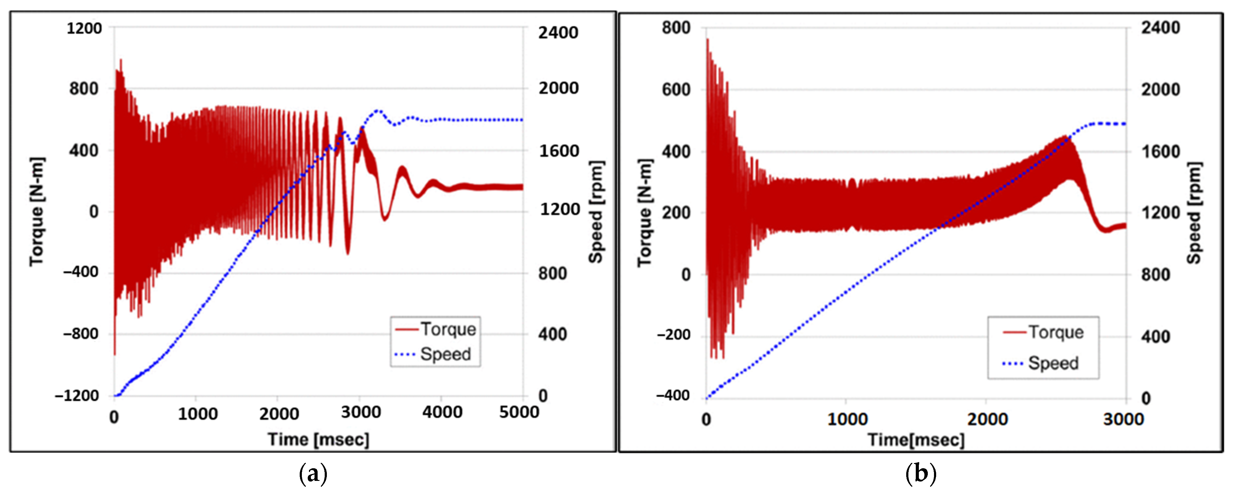
These synchronization dynamics are further illustrated in Figure 8, which presents three representative startup scenarios. In Case 1, the motor experiences significant oscillations during startup due to excessive braking torque produced by the permanent magnets. Although the motor possesses sufficient synchronous torque for steady-state operation, the design fails to achieve synchronization, rendering it unsuitable for practical use. In Case 2, the magnets are undersized, resulting in insufficient synchronous torque to maintain operation under rated conditions. Despite the motor initiating rotation, synchronization fails due to the presence of high load torque, elevated inertia, or a combination of both—each of which imposes significant demands during the pull-in phase. In contrast, Case 3 demonstrates successful synchronization. This outcome is achieved through a carefully optimized balance—selecting magnets that provide adequate synchronous torque without introducing excessive braking torque while also ensuring that the load torque and inertia remain within permissible limits. This case underscores the importance of holistic design optimization to ensure reliable startup and stable synchronous operation.
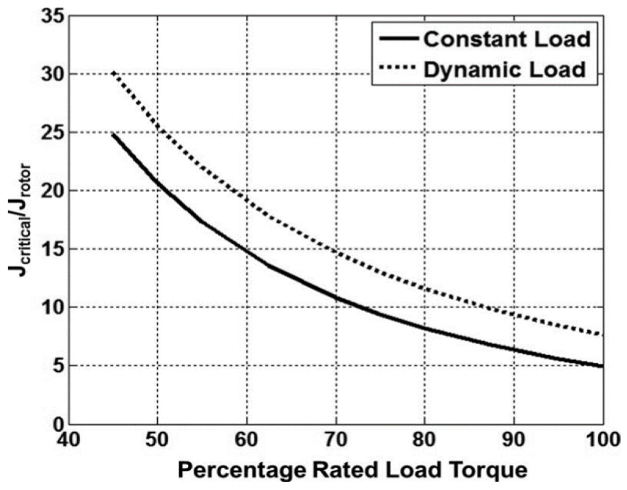
This interplay between load torque, inertia, and synchronization capability is further quantified in Figure 9, which presents the relationship between critical inertia and load torque for a 1 HP, 208 V, four-pole line-start Interior Permanent Magnet (IPM) motor under both constant and dynamic load conditions. As shown, the motor’s allowable inertia—the maximum inertia with which it can still achieve synchronization—decreases progressively as the load torque approaches its rated value. When operating under light load torque, the motor is capable of synchronizing even with relatively large inertial loads. However, synchronization becomes increasingly challenging as the load torque increases. In particular, dynamic loads, which typically require lower torque at reduced speeds, allow for a wider synchronization margin compared to constant loads. Once the load torque exceeds approximately 40% of the rated value, the critical inertia declines sharply along a nonlinear trajectory, indicating a rapid reduction in the motor’s synchronization capability. This emphasizes the need for careful matching of load conditions with motor design parameters to ensure reliable pull-in performance [17].
The technical difficulty of achieving synchronization under high-inertia conditions is reflected in the synchronous motor standard (NEMA SM1 [19]), which specifies that the critical inertia ratio J c r for LSPMSMs should be only 3–6% of that allowed for induction motors of equivalent rating [20]. In induction motors, the maximum allowable load inertia is primarily constrained by the thermal rise during acceleration, whereas in LSPMSMs, synchronization capability defines the limit. Despite this, LSPMSMs are well-suited for many general-purpose applications—particularly fans, pumps, and similar systems—which typically involve low to moderate inertia and modest starting torque. These characteristics make them viable and energy-efficient alternatives to induction motors in fixed-speed applications.

3.3. Effect of Rotor Resistance on Performance

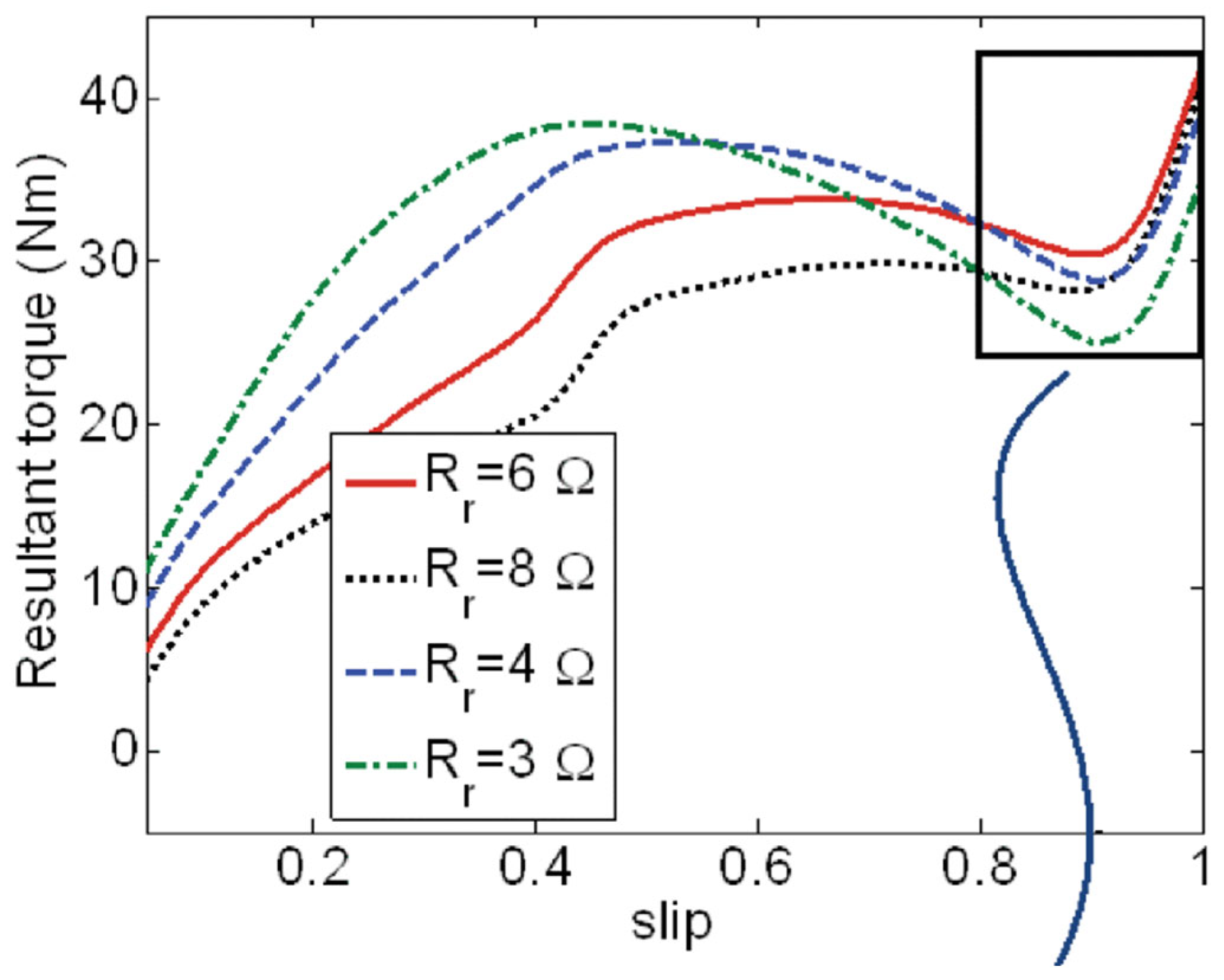
Rotor cage resistance plays a pivotal role in determining the startup and synchronization behavior of Line-Start Permanent Magnet Synchronous Motors (LSPMSMs). Extensive simulation studies have demonstrated that an optimal value of rotor resistance exists, which ensures both effective damping of load disturbances and improved startup performance. This optimal resistance minimizes the depth of the torque dip occurring at high slip values—commonly referred to as the critical torque, which directly impacts the motor’s ability to initiate and complete synchronization [21].
Importantly, the braking torque generated by the permanent magnets remains independent of the cage resistance, while the peak cage torque is also largely unaffected. However, the slip at which peak torque occurs is significantly influenced by rotor resistance. Therefore, synchronization performance is maximized when the peaks of both braking and cage torque align at the same slip value, resulting in a more balanced net torque and minimizing detrimental torque dips.
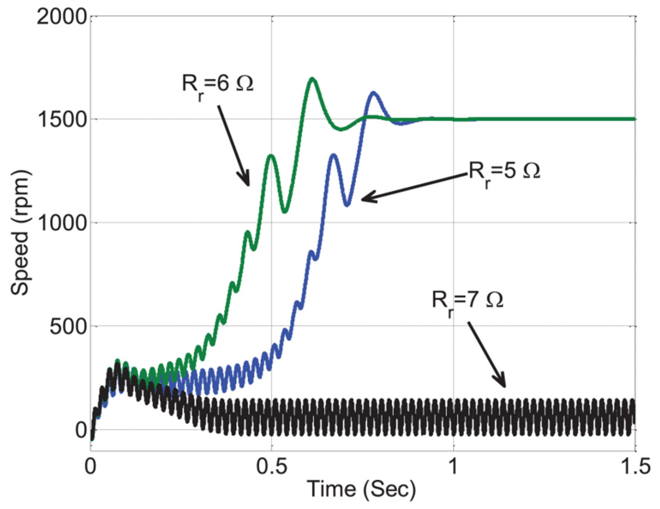
As illustrated in Figure 10, increasing the rotor resistance up to an optimal value (approximately 6 Ω in this case) leads to a corresponding rise in the critical torque. Beyond this threshold, however, any further increase in rotor resistance reduces the critical torque and deteriorates the motor’s startup capability. This confirms that, while rotor resistance is a key design parameter for improving synchronization, it must be finely tuned to avoid adverse effects on overall performance. Moreover, since rotor cage resistance is temperature-dependent—varying by up to 50% between cold and hot operating states [20]—designers must account for thermal effects to ensure the resistance remains near optimal across the motor’s typical operating range.
The sensitivity of startup performance to rotor resistance is further highlighted in Figure 11, which shows that the motor fails to achieve synchronization under high-inertia load conditions when the rotor resistance deviates significantly from its optimal value.
In conventional induction motor design, reducing rotor resistance (e.g., by increasing the conductor cross-sectional area) typically reduces slip and improves efficiency. However, this principle does not directly apply to LSPMSMs. In these motors, a larger cage cross-section may obstruct the magnetic flux path or weaken the electromagnetic interaction, leading to increased slip and reduced synchronization capability.
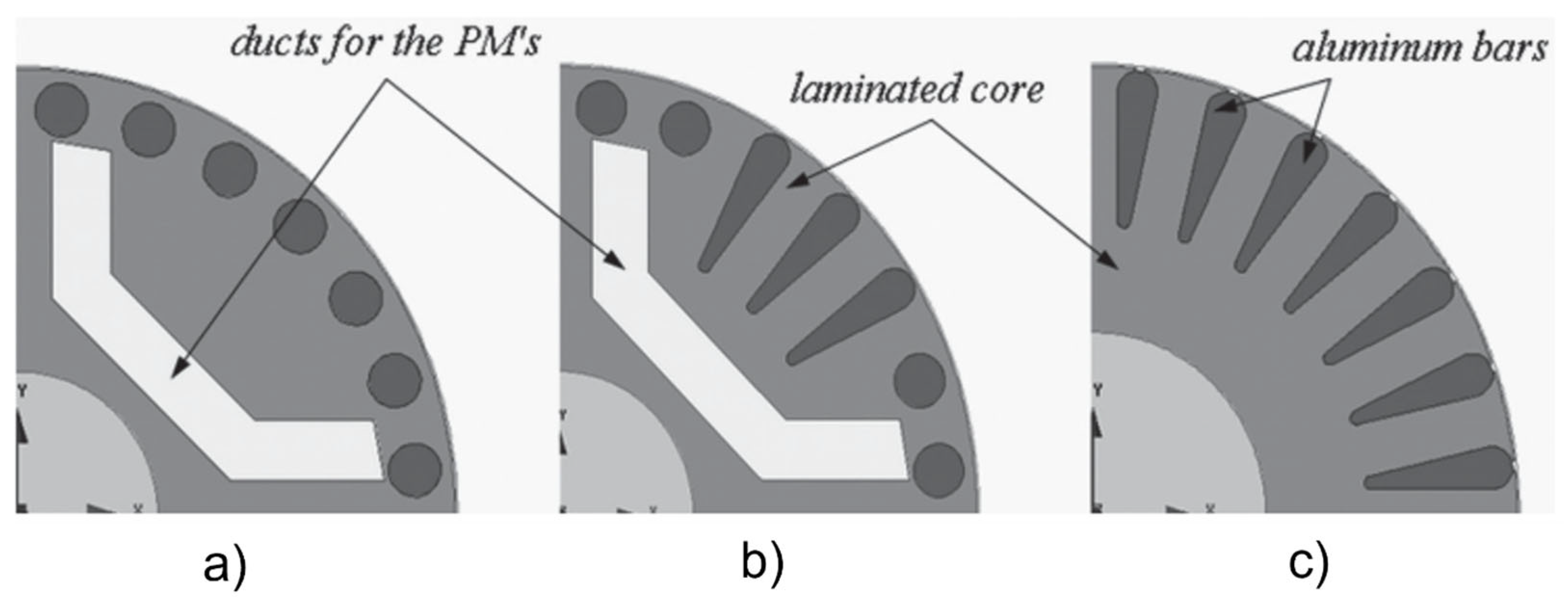
Furthermore, rotor cage design geometry has a notable influence on dynamic behavior. A comparative analysis presented in [22] examines symmetrical and asymmetrical rotor cage configurations (Figure 12), highlighting how structural modifications to the rotor can significantly affect motor performance across a wide range of speeds. At synchronous speed, the asymmetrical design induces greater torque pulsations due to magnetic asymmetry and rotor–slot interactions. However, near synchronization (e.g., at 0.83 pu speed), the asymmetrical cage delivers approximately 40% higher synchronizing torque than the symmetrical counterpart, thereby enhancing the motor’s ability to achieve and maintain synchronous operation during startup. This increase in synchronizing torque is primarily attributed to the optimized placement and deepening of selected rotor bars, which improve asynchronous torque characteristics. At lower speeds (e.g., 0.13 pu), the asymmetrical design also helps suppress parasitic torque components and unwanted torque ripple arising from complex harmonic interactions between the stator and rotor slots.

3.4. Influence of Magnetizing Inductance on Performance

The magnetizing inductance L m d of a Line-Start Permanent Magnet Synchronous Motor (LSPMSM) significantly influences both its startup performance and synchronization capability. As noted in prior analyses [23], a fundamental trade-off exists: a high magnetizing inductance enhances asynchronous startup by reducing the braking torque (as shown in Equation (12)), but it may hinder synchronization by lowering the available synchronous torque (see Equation (13)), which is essential for successful pull-in. Conversely, a lower magnetizing inductance improves synchronization by increasing the saliency ratio, thereby boosting synchronous torque, but this comes at the cost of weaker starting torque. Additionally, the paper demonstrates that braking torque is strongly influenced by both the magnetic flux and magnetic saliency, which are, in turn, dependent on the magnet dimensions and rotor design.
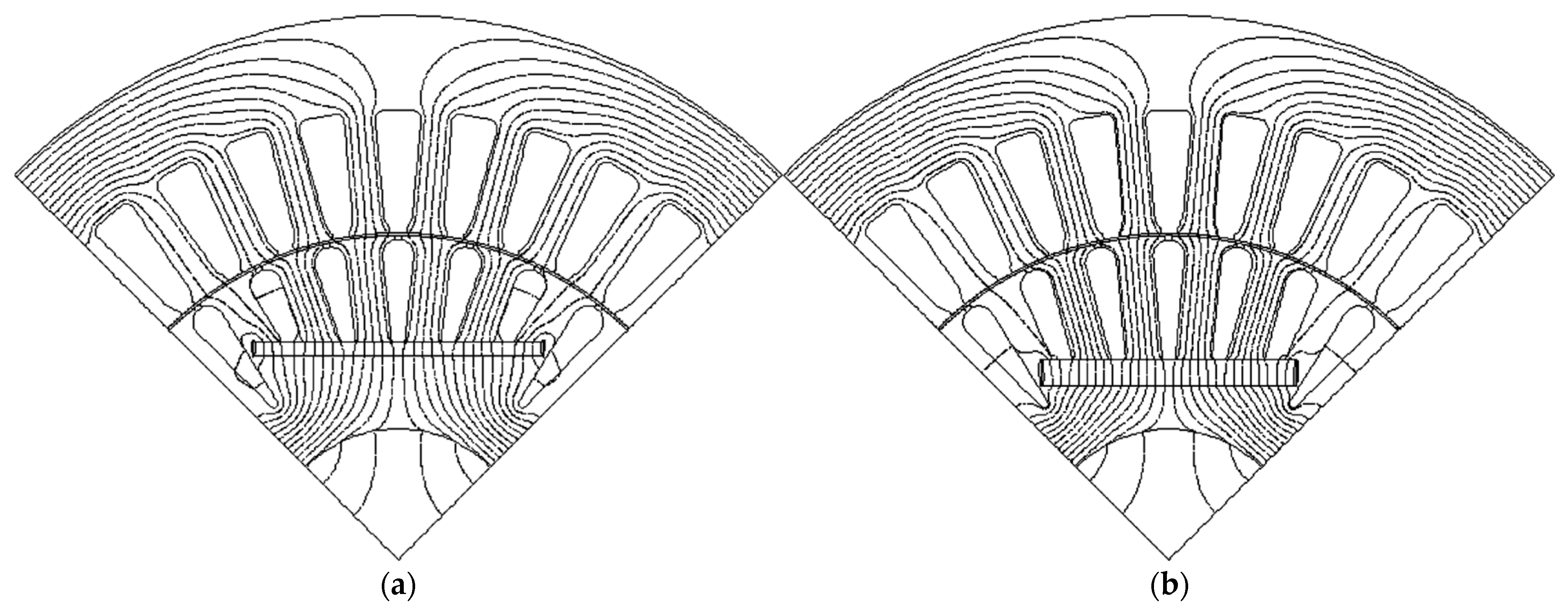
As a result, the optimal magnetizing inductance must be selected based on the specific application requirements. For instance, in applications involving constant loads that demand high starting torque or rapid acceleration—such as conveyors or heavy-duty machinery—a higher magnetizing inductance is preferable. This configuration can be achieved by using thinner magnets with greater axial width, as demonstrated in Figure 13a [23]. The study further shows that, in such cases, motors with higher L m d can handle higher constant load thresholds, offering greater robustness during the early startup phase.
In contrast, for applications where starting torque requirements are moderate or low, such as fans, pumps, or low-viscosity compressors, a lower magnetizing inductance yields better synchronization performance. This can be realized by employing thicker magnets, which increase saliency and improve synchronizing torque behavior, as illustrated in Figure 13b. The paper’s finite element simulations also confirm that motors with lower L m d exhibit superior synchronization under variable loads, such as fluid pumping profiles, thereby making them suitable for such applications.
Together, these configurations highlight how variations in magnet dimensions directly influence magnetizing inductance and, consequently, the motor’s overall dynamic behavior.

3.5. Impact of Supply Voltage on Synchronization

Beyond motor geometry and inductance tuning, the supply voltage level is another critical factor influencing the synchronization capability of LSPMSMs. While rotor and magnet configurations define the motor’s intrinsic torque characteristics, the external voltage supply determines the energy available to accelerate the rotor and overcome braking torque during the pull-in phase.
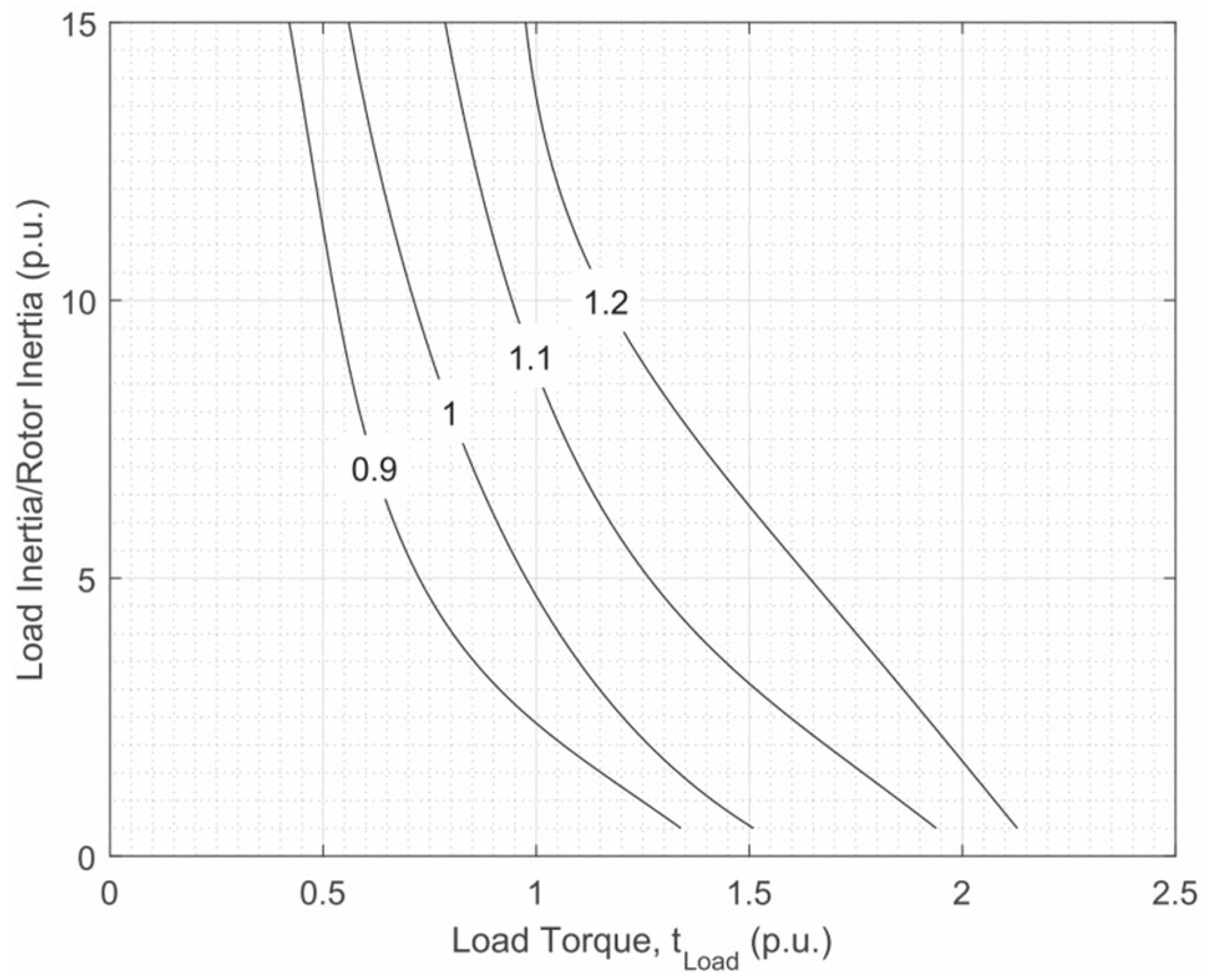
Figure 14 illustrates the impact of supply voltage on synchronization performance for a line-start permanent magnet synchronous motor. The curves represent different voltage levels expressed in per-unit (p.u.) values. As the supply voltage decreases—for example, from 1.2 p.u. to 0.9 p.u.—the region of successful synchronization shrinks markedly. At lower voltages, the motor can only synchronize under lighter load torques and reduced inertial conditions. This is primarily because reduced voltage limits the stator flux and corresponding cage torque during startup, weakening the motor’s ability to bring the rotor to synchronous speed [24].
These findings underscore the importance of maintaining a stable and sufficient supply voltage—particularly in industrial environments where voltage drops may occur during load surges or network fluctuations. For LSPMSMs deployed in such contexts, voltage regulation strategies or compensation through design margins may be necessary to ensure robust synchronization under real-world operating conditions.

3.6. Performance Comparison with IMs and LSSynRMs

Having explored the internal design parameters and external operating conditions that influence the performance of LSPMSMs, it is essential to compare their behavior with other widely used line-start motor technologies. These include squirrel-cage Induction Motors (IMs) and Line-Start Synchronous Reluctance Motors (LSSynRMs)—each offering distinct characteristics in terms of starting dynamics, current profile, and operational efficiency.
Figure 15 compares the torque–speed characteristics of an LSPMSM and a traditional induction motor during Direct-On-Line (DOL) startup. While induction motors experience torque pulsations primarily during the initial acceleration phase, these oscillations tend to diminish as the rotor approaches steady-state speed. In contrast, the LSPMSM is subject to continuous torque pulsations throughout the starting period due to the interaction between the permanent magnets and the rotating stator field. These torque variations must be carefully considered when selecting coupling mechanisms to ensure mechanical stability and acceptable component lifespan [20].
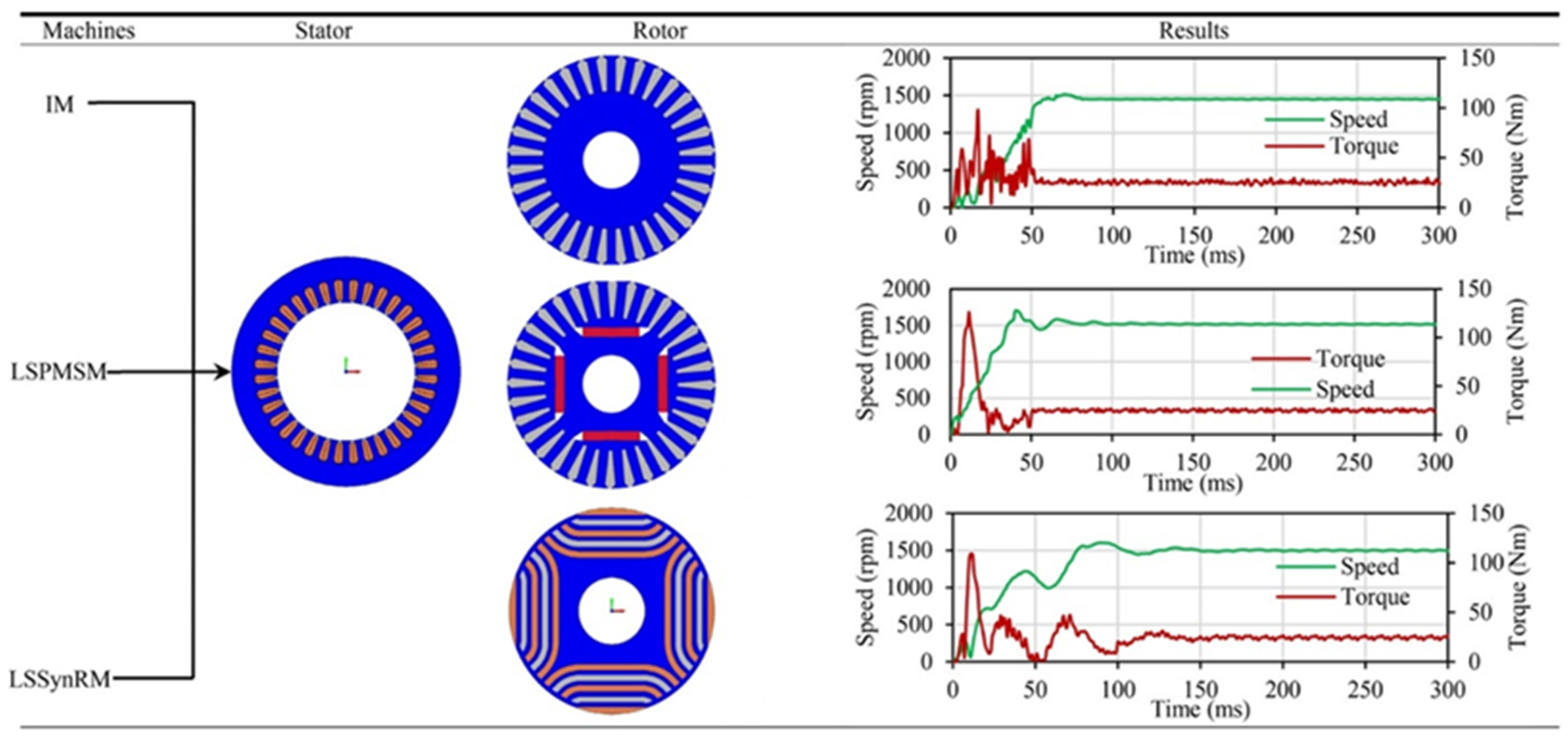
The synchronization behavior of LSSynRMs is illustrated in Figure 16, which shows that they generally exhibit a longer pull-in time compared to both LSPMSMs and induction motors. This is due to their reliance solely on reluctance torque, without the aid of permanent magnets. As a result, their synchronization margins are lower, and their performance is more sensitive to variations in load torque and inertia [4].
According to Miller [6], the superior synchronization capability of LSPMSMs stems from the additional magnet alignment torque, which increases the available synchronizing energy. In LSSynRMs, rotor pole slips are limited to 180 electrical degrees, whereas in LSPMSMs, they span the full 360 electrical degrees. This results in a larger area under the synchronizing torque curve T s ( δ ) , providing LSPMSMs with a greater energy reserve for synchronization, especially under demanding conditions.
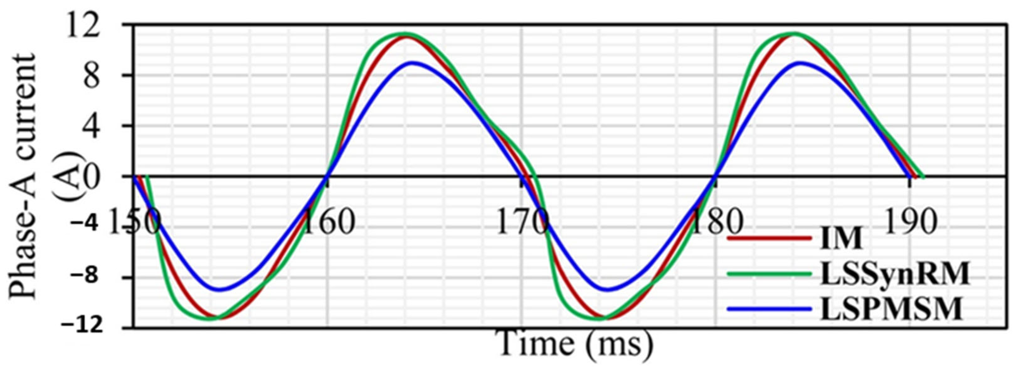
A further comparison is provided in Figure 17, which shows the phase-A current profiles under full-load conditions. Both IMs and LSSynRMs draw higher peak current during steady-state operation, which contributes to increased I2R losses and elevated thermal stress. In contrast, the LSPMSM maintains a lower current amplitude, primarily due to the reduced magnetizing current requirement enabled by the embedded permanent magnets. This contributes to lower losses, improved thermal behavior, and enhanced overall system reliability.
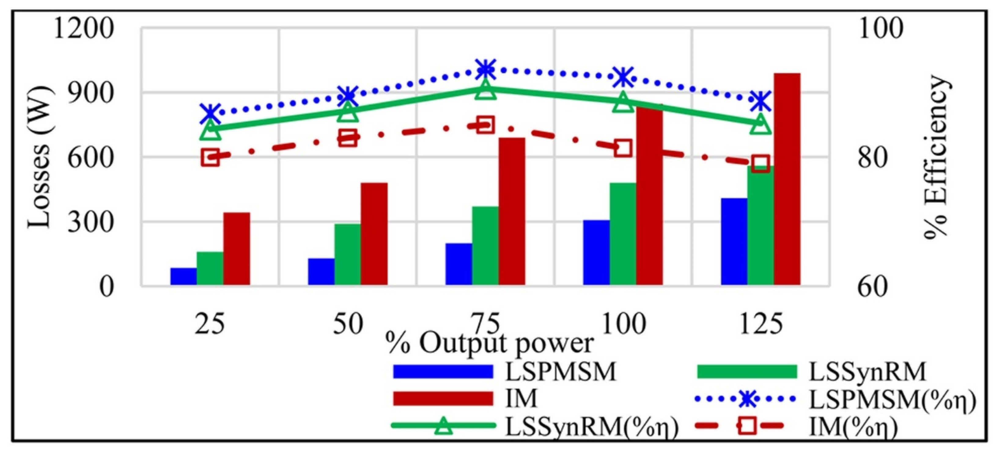
Figure 18 presents a comparison of total losses and corresponding efficiencies across different output power levels for three motor types: a 3.7 kW Line-Start Permanent Magnet Synchronous Motor (LSPMSM), a Line-Start Synchronous Reluctance Motor (LSSynRM), and a conventional Induction Motor (IM). These motors were modeled and analyzed in the review by Ganesan et al. [4], where finite element analysis was used to simulate their performance. The study showed that, while all machines exhibit increased losses with rising load, the LSPMSM consistently maintains lower total losses and higher efficiency across the operating range. At full load, it outperforms both the IM and LSSynRM, achieving efficiency levels compliant with the IE4 premium efficiency class.
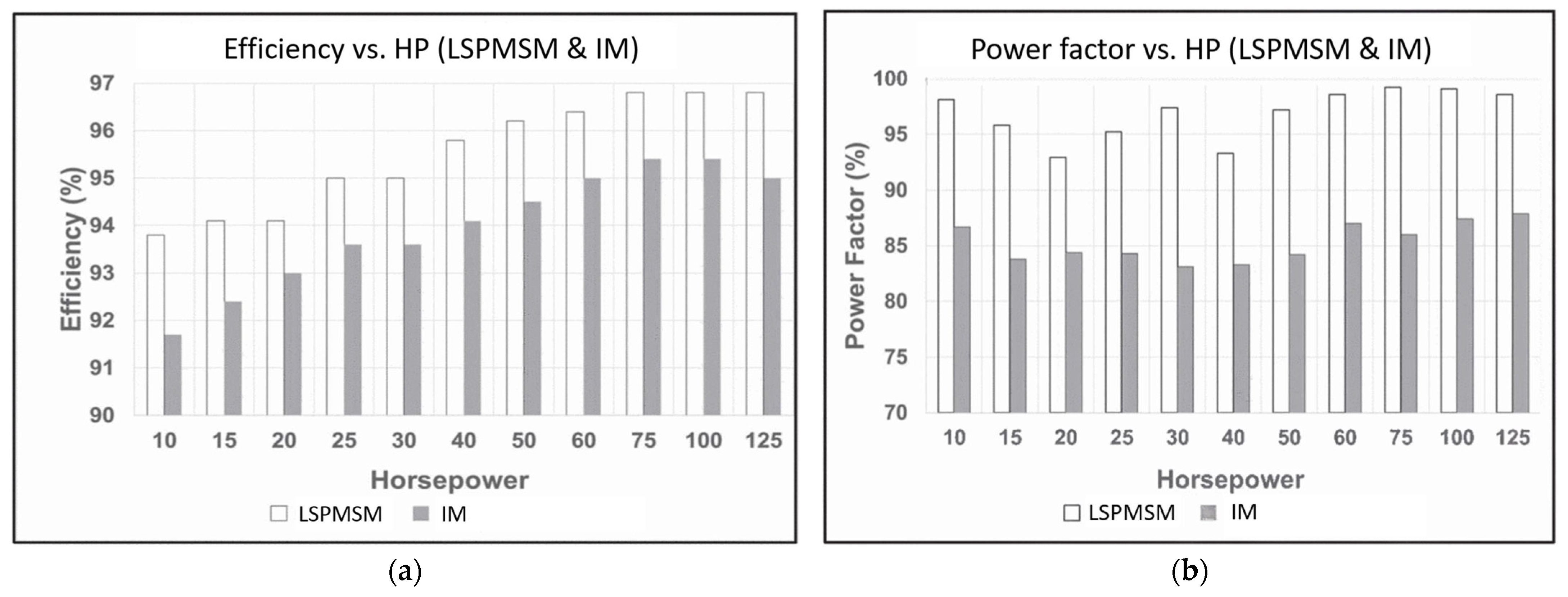
This operational advantage is further illustrated in Figure 19, which compares the power factor across different power ratings (10–125 HP) for Line-Start Permanent Magnet Synchronous Motors (LSPMSMs) and conventional induction motors. LSPMSMs consistently exhibit a higher power factor, which—when combined with their superior efficiency—results in lower full-load current for a given power rating.
Collectively, these comparisons underscore the advantages of LSPMSMs in fixed-speed applications. While induction motors remain cost-effective and widely adopted, their efficiency improvements are fundamentally limited by rotor losses—particularly from induced cage currents, which can account for up to 25% of total losses [3]. On the other hand, LSSynRMs offer a magnet-free solution with favorable material costs but often fall short in power factor and efficiency, especially under variable load conditions.
Despite their advantages, LSPMSMs face practical startup limitations under Direct-On-Line (DOL) operation. Typically, the maximum load inertia that can be reliably started is around 20% of the threshold defined by the standard for induction motors [25]. However, this is usually sufficient for typical industrial applications, especially in pump systems, where load inertia remains well within acceptable limits.
In variable-speed scenarios, LSPMSMs offer even greater operational flexibility. When used with variable frequency drives (VFDs), they can operate in simple scalar control mode (volts-per-Hertz) due to the presence of the induction cage. This eliminates the need for position feedback or the advanced control algorithms required by cage-less PM motors [5], simplifying integration and reducing system costs. Furthermore, with VFDs, startup is no longer limited by load inertia but instead by the drive’s current limit, which governs available torque and acceleration time.
In conclusion, LSPMSMs combine robust self-starting capability with high energy efficiency and operational versatility, making them strong candidates for both fixed-speed and variable-speed industrial applications.

4. Evolution and Innovation in Line-Start PM Motor Design

4.1. Historical Rotor Topologies (1950s–2000)

The evolution of Line-Start Permanent Magnet Synchronous Motors (LSPMSMs) spans over seven decades, beginning with foundational innovations that laid the groundwork for today’s high-efficiency machines. For conciseness, the acronym LSPMSM is used throughout this section.
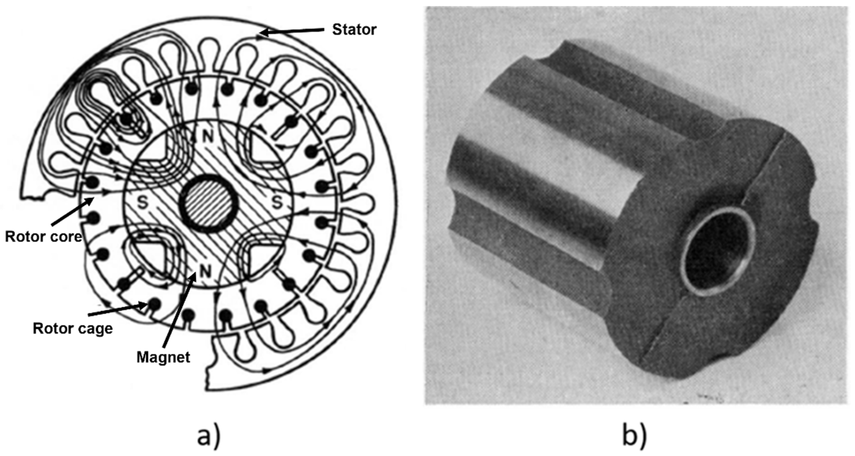
One of the earliest documented examples is the “Permasyn” motor introduced by Merrill in 1955 (Figure 20) [26]. This pioneering motor used a one-piece Alnico V magnet casting embedded within the rotor, enabling synchronous excitation while at the same time retaining a squirrel-cage structure to provide robust induction startup capability. Merrill’s detailed analysis of magnetic flux behavior under different operating conditions offered valuable early insights into magnet behavior, including the necessity of using sufficiently high-coercivity magnets to effectively withstand demagnetization during asynchronous operation. Although the design was inherently limited by the magnetic material technologies available at the time, this concept nonetheless marked a significant milestone in the historical development of LSPMSMs.
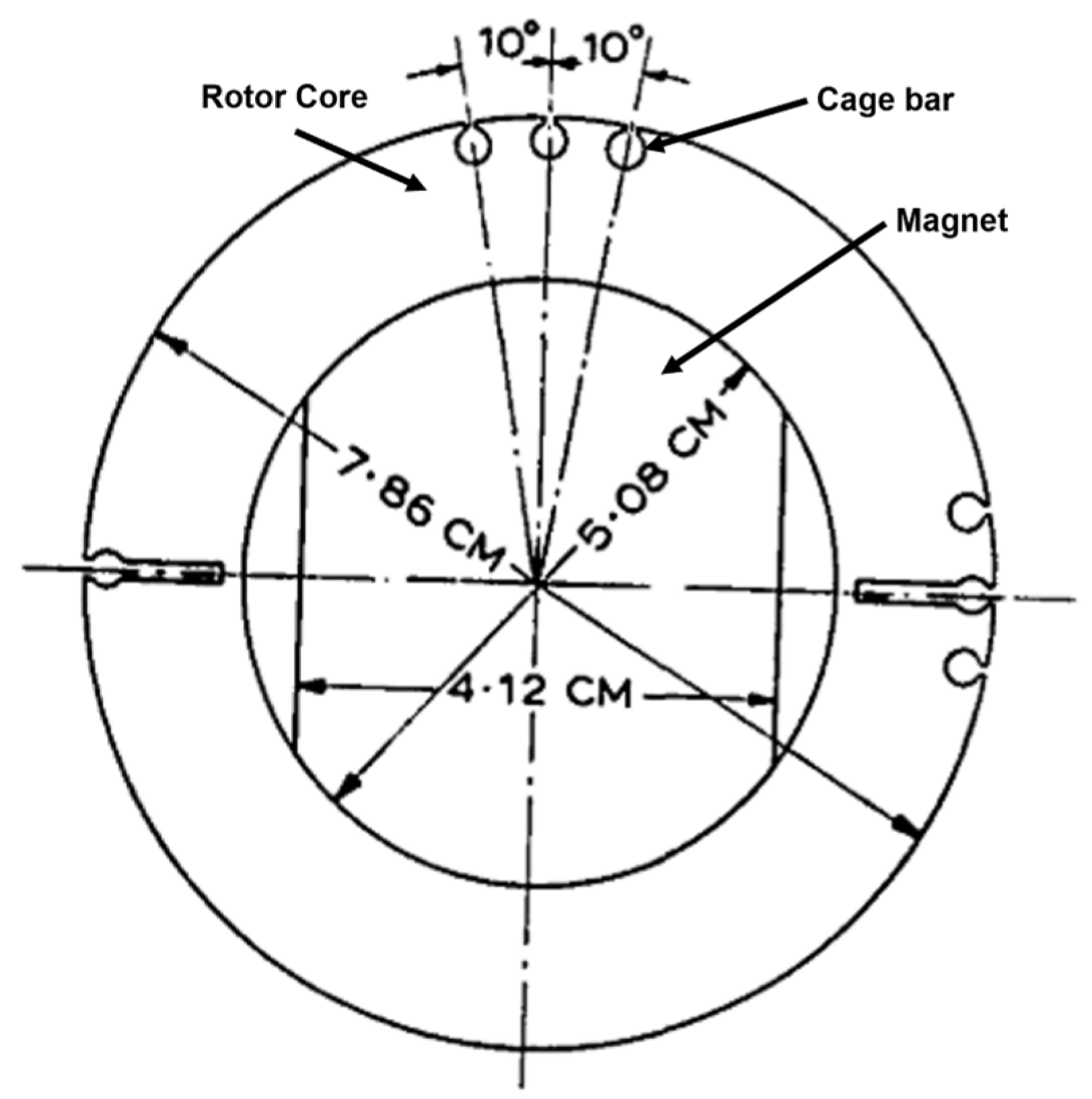
Building on Merrill’s foundation, Cahill and Adkins retrofitted a small induction motor with a block of Ticonal G magnet embedded inside the rotor (Figure 21) [27]. Although the air-gap flux was reduced, leading to lower pull-out torque, their work demonstrated how optimized rotor and magnet design could yield meaningful gains in both power factor and efficiency. These insights contributed to the evolving understanding of LSPMSM rotor topologies.
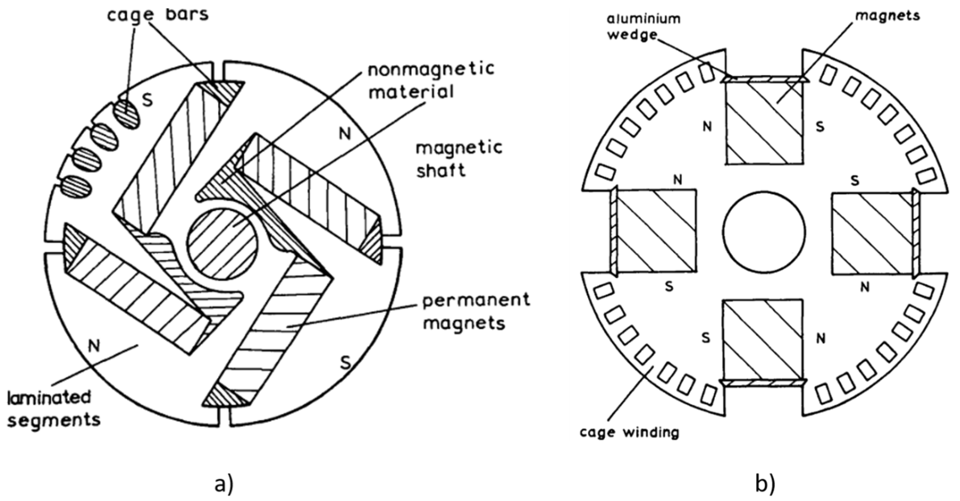
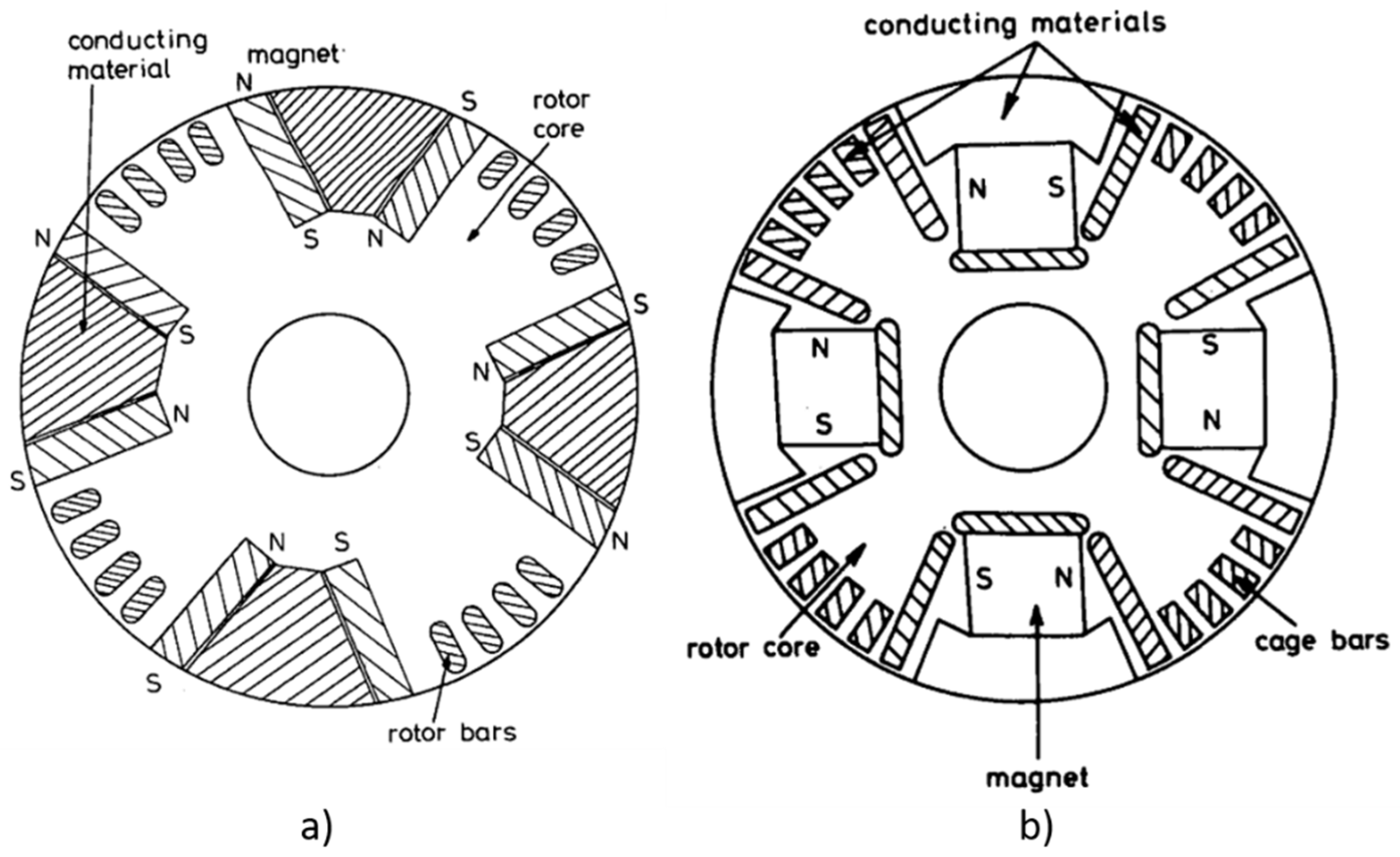
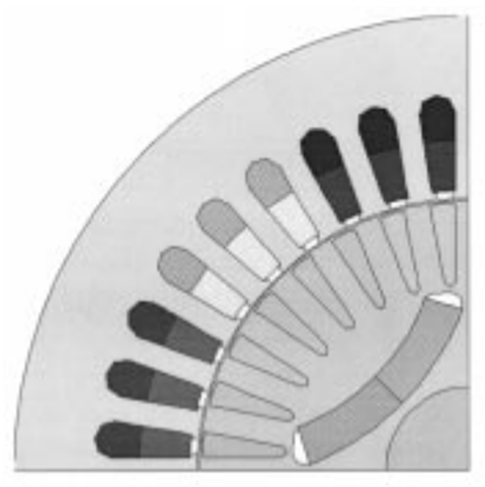
In the early 1970s, Binns and Barnard [28] reviewed a range of commercial PM motor designs, including segmented rotor geometries made of laminated segments separated by nonmagnetic material (Figure 22a). They proposed a more manufacturable and robust continuous laminated rotor, where magnets were secured using iron overhangs or aluminum wedges (Figure 22b). Their focus on high-coercivity magnets like Hycomax III and Feroba II further advanced the development of reliable direct-on-line synchronous machines.
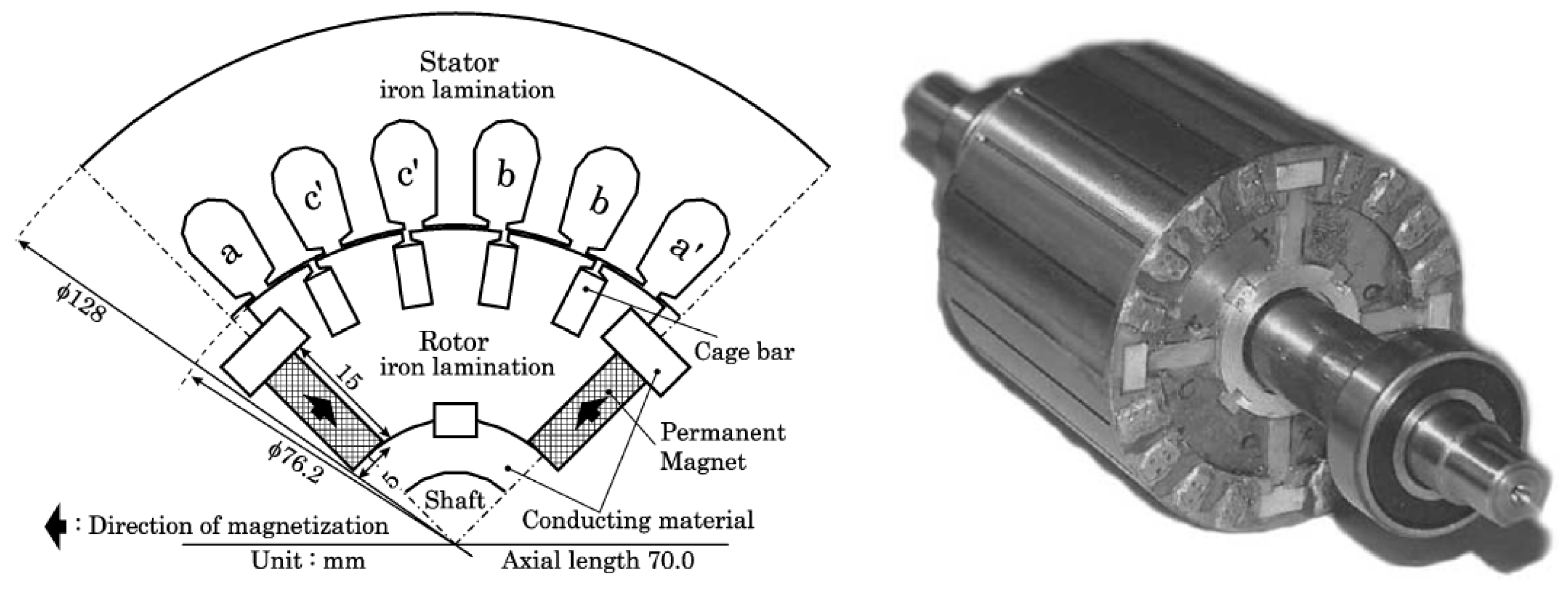
Later, Binns, Barnard, and Jabbar introduced rotor geometries featuring ceramic magnets embedded in flux barriers (Figure 23) [29]. These configurations, analyzed using Finite Element Analysis (FEA), delivered a maximum efficiency of 78% and a power factor of 0.63, with output power reaching 1.5 kW under optimal loading conditions. The ceramic magnets used in these designs offered significantly higher coercivity compared to the Alnico magnets employed in earlier configurations, thereby enhancing resistance to demagnetization during operation.
By 1981, an improved design by Binns and Jabbar employed non-radial magnet axes within a four-pole rotor to enhance both asynchronous startup and synchronous performance (Figure 24) [30]. Tested at 50 Hz, the motor achieved an efficiency of 85% and a power factor exceeding 0.96 at a rated power of 2.5 kW. The non-radial magnet orientation directed more flux into the air gap, strengthening the synchronous torque and contributing to the motor’s high efficiency and power factor.
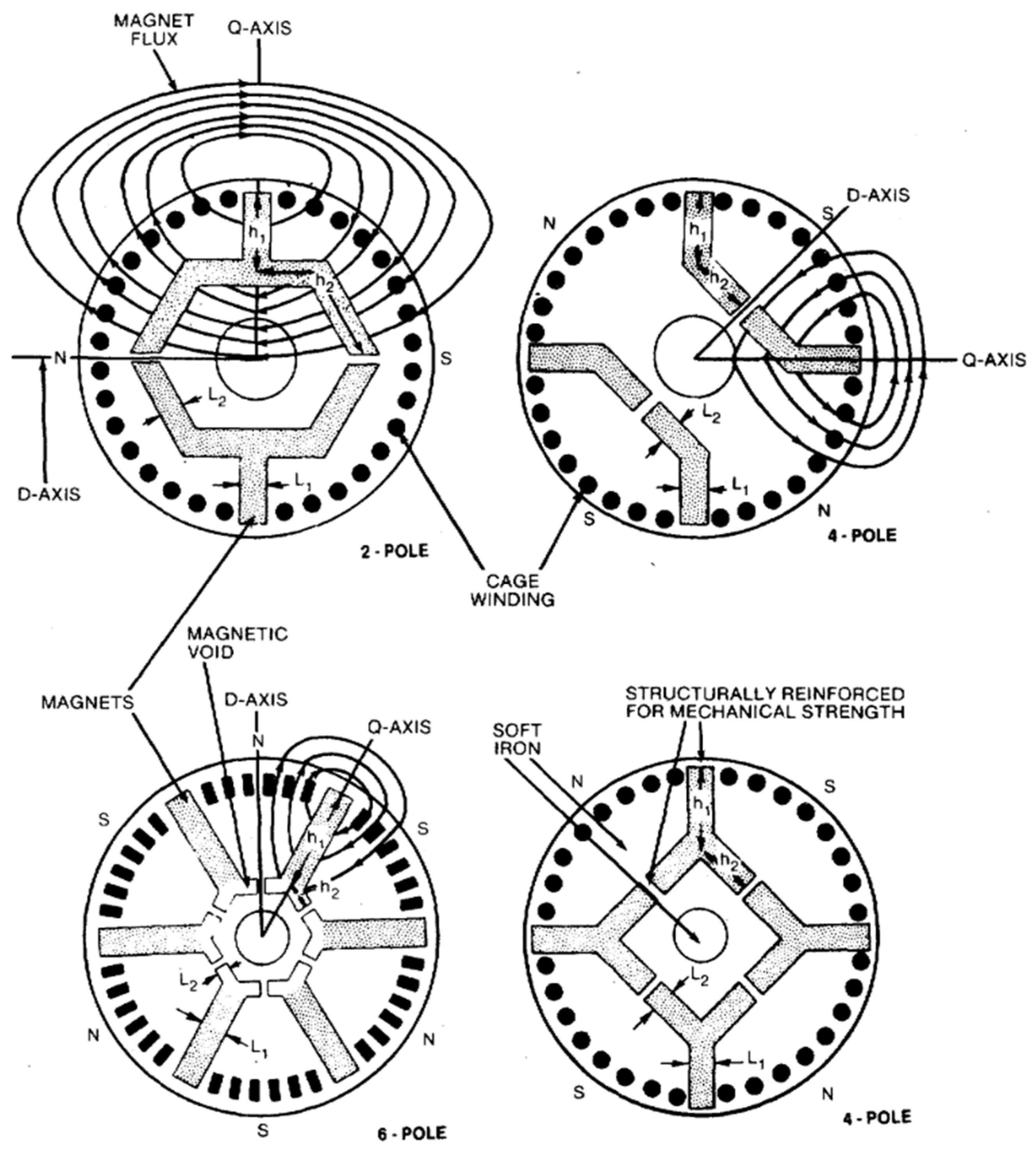
In the early 1980s, Honsinger and Miller [6,31], both affiliated with General Electric, contributed several new rotor concepts. Honsinger advanced the development of LSPMSMs by analyzing Interior Permanent Magnet (IPM) configurations, where magnets are embedded within the rotor core (Figure 25) [31]. These rotors incorporated a squirrel cage for asynchronous startup and protection against demagnetization. Honsinger’s work provided a detailed field analysis of various interior magnet geometries, deriving expressions for the air-gap fields, d- and q-axis inductances, and open-circuit voltage. The study demonstrated that placing magnets inside the rotor, combined with optimized flux barriers and bridges, improves the saliency ratio ( L s q / L s d ), enhancing synchronous torque and efficiency. Furthermore, the interior placement offers mechanical robustness and reduces the risk of demagnetization compared to surface-mounted designs, making IPM configurations well-suited for variable-speed applications.
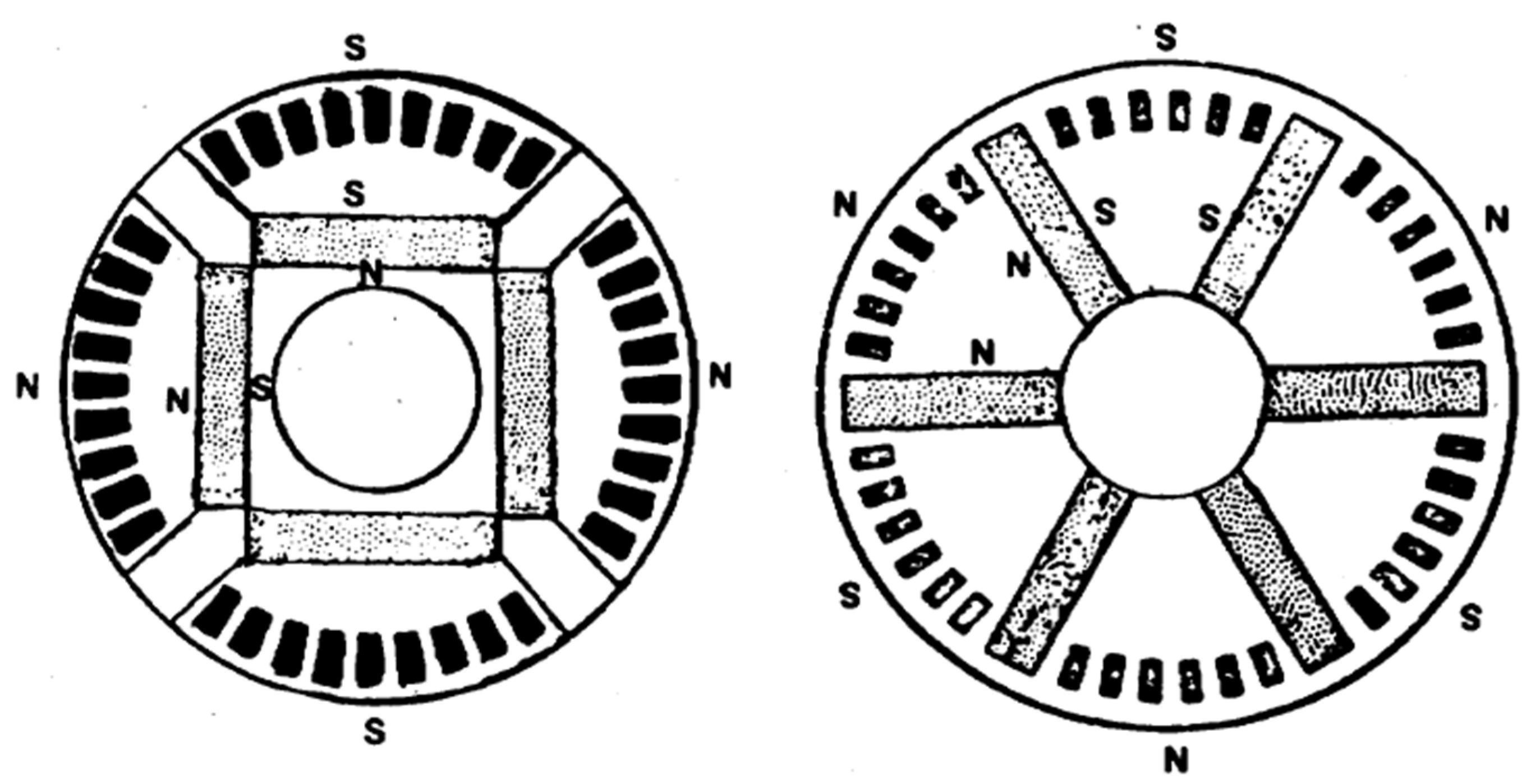
Miller [6], on the other hand, introduced simplified rotor shapes optimized for synchronization reliability across varied startup conditions (Figure 26). His designs prioritized practical manufacturability and consistent performance over a wide range of load inertias and torque profiles. By carefully tuning the rotor geometry, including the cage design and magnet placement, Miller improved the asynchronous torque near synchronous speed, which is critical for successful pull-in. Additionally, his analysis highlighted the importance of minimizing magnet braking torque and achieving a steep asynchronous torque–speed characteristic to enhance synchronization capability. These improvements allowed the motor to handle higher inertia loads and more demanding startup scenarios with greater reliability compared to earlier designs.
Further contributions came from Chalmers et al. in 1985 [32], who embedded radially oriented samarium–cobalt magnets within the rotor core (Figure 27). This configuration supported both DOL (direct-on-line) startup and consistent performance across various frequencies, making it a good candidate for VFD-driven applications. Their analysis highlighted the benefits of the interior magnet layout, which provided a favorable saliency ratio (Xq/Xd), improving both torque production and dynamic control under variable-frequency operation. In addition, the study addressed the impact of magnetic saturation on the q-axis reactance, showing that incorporating this variation into the two-axis model significantly improved the correlation between calculated and measured performance. The robust rotor design also enhanced mechanical integrity, allowing reliable operation under the high-speed and high-inertia load conditions often encountered in modern VFD applications. This motor delivered an efficiency of 80% and a power factor of 0.98 at a rated output of 275 W.
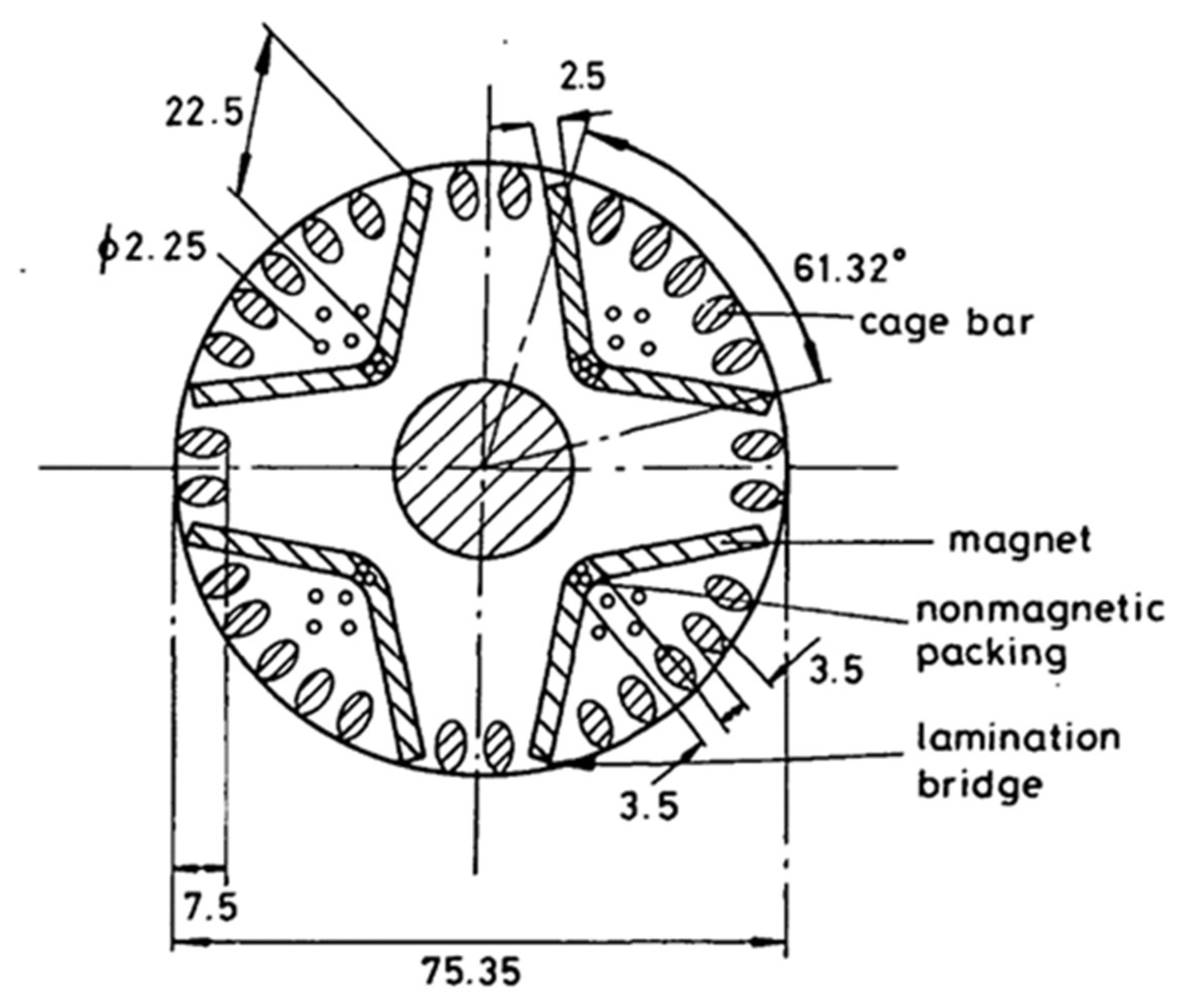
At the beginning of the 21st century, Knight and McClay introduced a practical LSPMSM rotor configuration featuring curved, embedded magnets within a conventional induction motor frame (Figure 28) [33]. Their design retained an unmodified rotor cage to ensure asynchronous startup and direct-on-line compatibility. Using time-stepped finite-element simulations, they demonstrated that the motor could reliably synchronize even under full-load starting conditions and achieve peak efficiency exceeding 89%, with a power factor greater than 0.85 at a rated output of 1.5 kW. The work clearly demonstrated the potential of LSPM designs to meet high-efficiency targets without requiring extensive mechanical redesign, thus offering an attractive path for industrial adoption.

4.2. Modern Rotor Designs

In 2004, Kurihara and Rahman proposed an interior magnet design using NdFeB magnets and deep rotor bars (Figure 29) [34]. Their structure balanced strong synchronous torque with reliable DOL starting, thanks to optimized flux barriers and sinusoidal EMF waveforms confirmed by an FEA simulation model. Aluminum conductors positioned between the magnets and rotor core serve as flux barriers and simultaneously function as cage windings, aiding asynchronous startup and synchronous transition. The motor delivered an efficiency of 87.3% and a power factor of 0.981 at a rated output of 600 W.
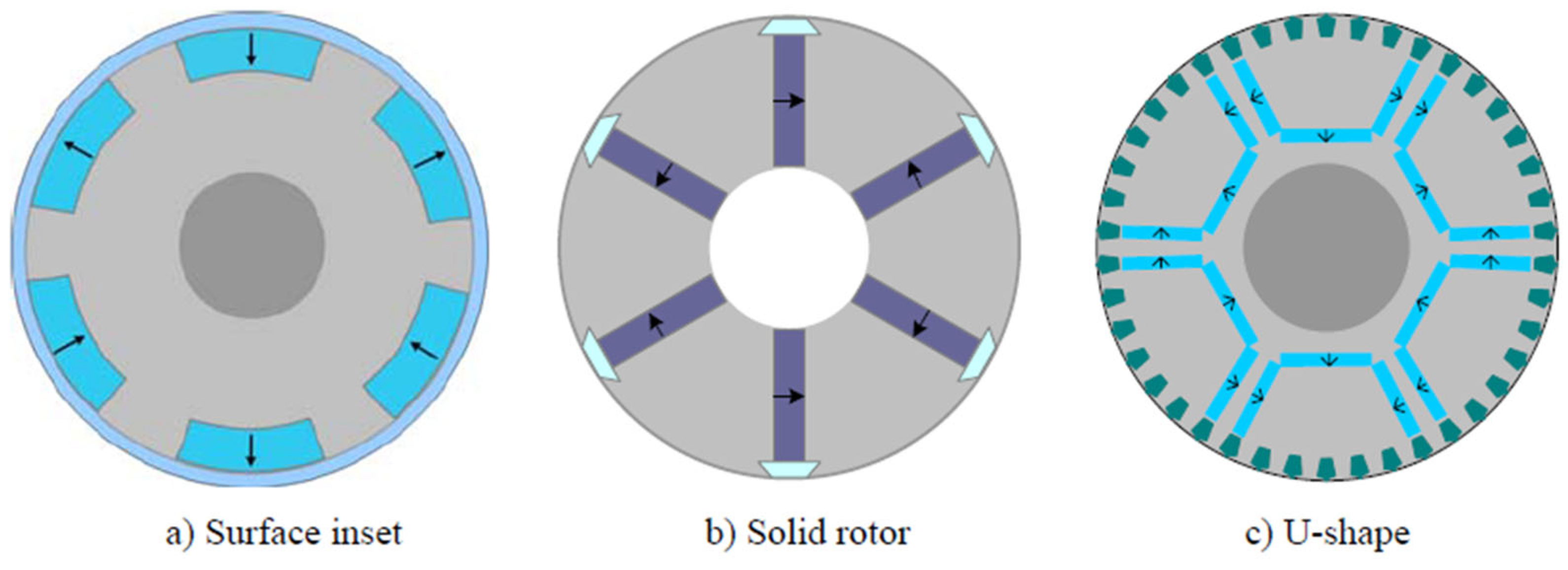
Between 2000 and 2015, researchers introduced a wide array of rotor topologies to address the growing demand for higher efficiency and improved synchronization in industrial applications. Ding et al. analyzed three different geometries for oil-pump use (Figure 30) [35], each with unique structural features and performance trade-offs. The first configuration employed surface-mounted magnets paired with a solid aluminum ring acting as the squirrel cage. While simple and cost-effective, this design generated substantial braking torque during startup and offered limited magnetic coupling, leading to lower efficiency and power factor. The second geometry used interior azimuthally magnetized permanent magnets embedded within a solid iron rotor. This layout enabled strong flux concentration and facilitated eddy current formation for robust asynchronous performance. The third configuration combined interior U-shaped magnets with a squirrel cage, achieving superior torque density and efficiency but introducing greater design complexity. Among these, the second design was identified as the most practical, offering a balanced trade-off between manufacturing ease, reliable synchronization, and high operating performance. It achieved an efficiency of 94.7% and a power factor of 0.91 for a 7.5 kW-rated motor.
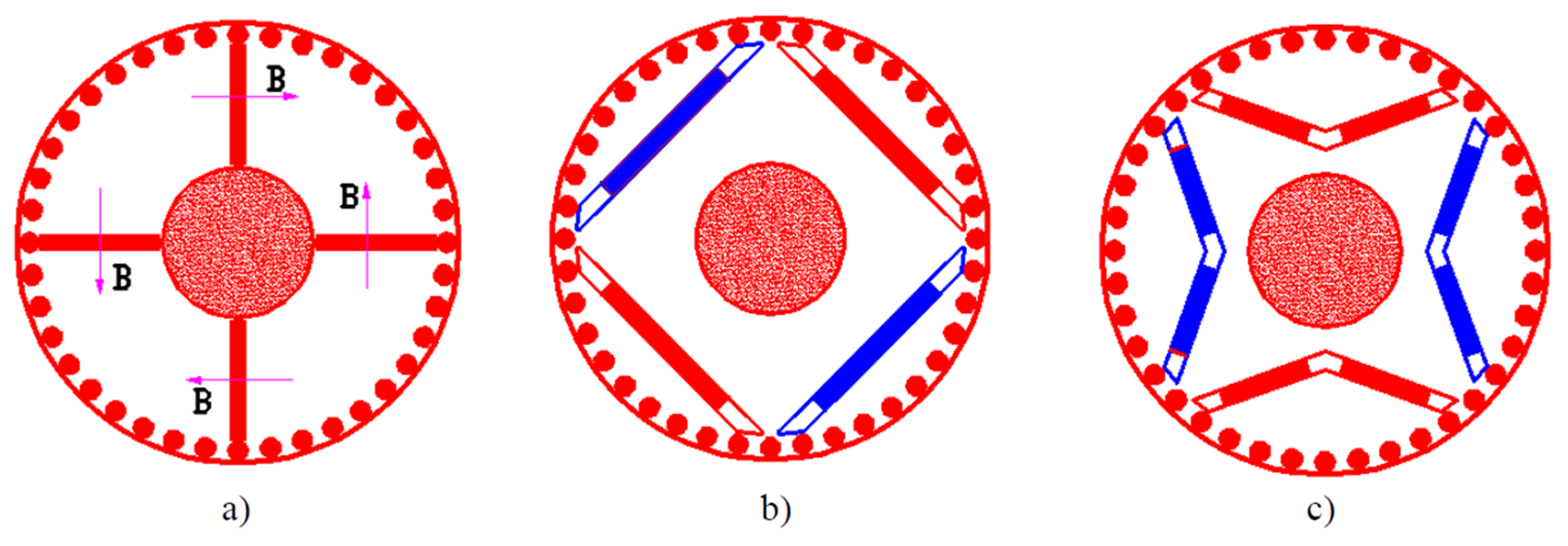
Elistratova [36] tested spoke-type, series, and V-shaped rotors (Figure 31). The designs were developed for a 7.5 kW, 4-pole operating at 1500 rpm and 400 V. Among the tested configurations, the V-shaped rotor topology achieved the highest performance, with a maximum efficiency of 93.0% and a power factor of 0.93, outperforming both the induction motor baseline and other LSPMSM variants. These results demonstrate the effectiveness of interior magnet arrangements in enhancing both torque production and energy efficiency.
Other notable designs include a dual-layer U-shaped rotor with NdFeB magnets optimized via genetic algorithms (Figure 32) [37]. This configuration featured two magnet layers of varying widths and pole arcs to enhance flux linkage and reduce torque ripple. A genetic algorithm was used to fine-tune magnet dimensions and rotor resistance, achieving high efficiency and reliable pull-in. Another noteworthy topology was a convex-profile IPM rotor (Figure 33) [38], developed using lumped parameter modeling and validated with FEA. This 7.5 kW, two-pole motor employed embedded rectangular magnets and flux barriers to optimize back-EMF and reduce torque ripple, reaching an efficiency of 94.7% and a power factor of 0.919.
More recently [39,40,41], induced-pole topologies (Figure 34) have been introduced to improve flux behavior and maintain high torque density and synchronization reliability. The Induced Pole Permanent Magnet Synchronous Motor (IPPMSM) features a rotor that structurally resembles a two-pole design but operates as a four-pole machine by magnetically inducing additional poles. This allows the number of permanent magnets to be halved while preserving the same total magnet volume to maintain demagnetization resistance. Compared to conventional induction motors of the same frame size, the IPPMSM delivers 33% more output power, achieves 88.2% efficiency, and operates at a power factor of 0.95.
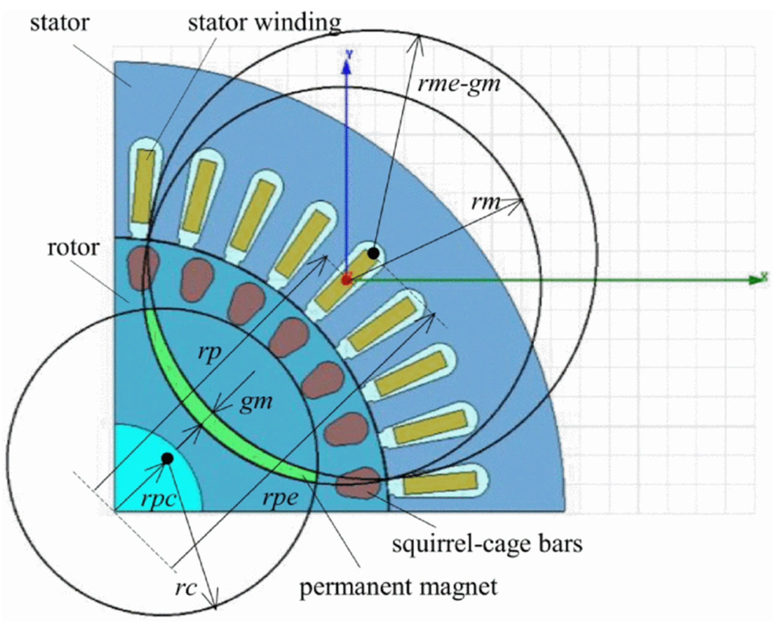
The hybrid powder-composite rotor (Figure 35) [42] exemplifies a distinct design pathway in LSPMSM development. It uses Soft Magnetic Composite (SMC) materials to reduce eddy current losses and incorporates arc-bonded NdFeB magnets along with a squirrel cage to ensure robust asynchronous performance. Furthermore, the powder-based construction—where SMC powder is compacted in a mold—allows for greater flexibility in rotor geometry, enabling precise tuning of magnet dimensions, pole embrace (rc), and cage bar placement to optimize both starting and synchronous performance. Simulation studies [42] demonstrated that adjusting magnet thickness, magnet arc angle, and pole coverage can effectively balance asynchronous torque and synchronization capability. The hybrid rotor achieved 93% efficiency and 0.95 power factor at a rated output of 3.45 kW while offering superior manufacturing flexibility. Additionally, the lower density of SMC material results in a reduced rotor weight, which decreases thermal inertia and, combined with lower eddy current losses, leads to improved thermal performance under dynamic operating conditions.
This historical and technological journey highlights the continuous refinement of rotor geometries and magnet arrangements in pursuit of optimized startability, efficiency, and industrial viability.

4.3. Emerging Topologies and Startability Solutions

To address the persistent challenges related to starting performance in LSPMSMs—particularly their limitations under high-inertia conditions compared to induction motors—recent studies have proposed several configuration strategies. These designs aim to improve the synchronization process and extend the starting capability of LSPMSMs to levels comparable to traditional induction machines. The following subsection presents a selection of such innovations, highlighting their structural and electromagnetic features and their contributions to enhanced motor functionality.

4.3.1. Pole-Changing Configurations

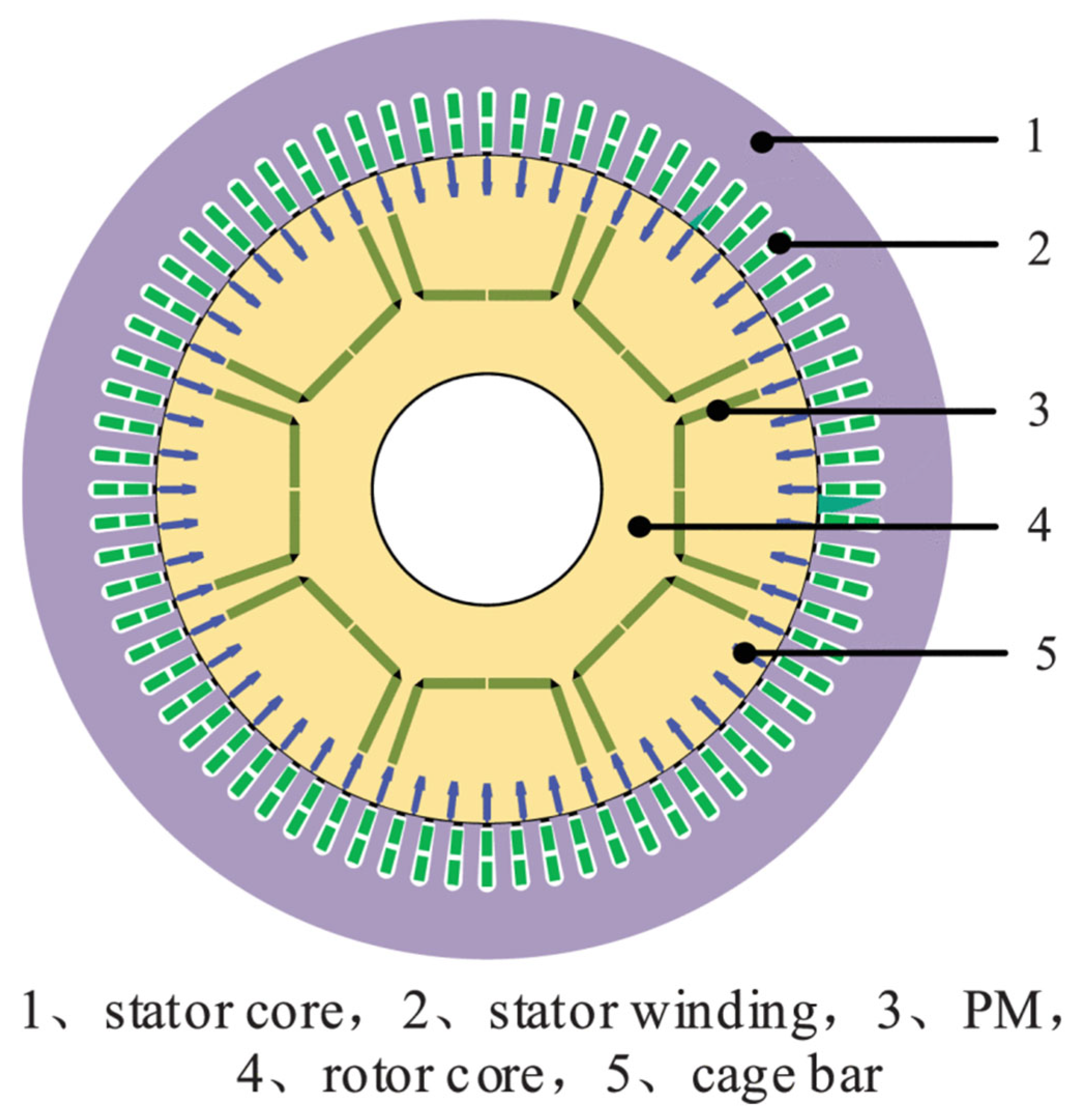
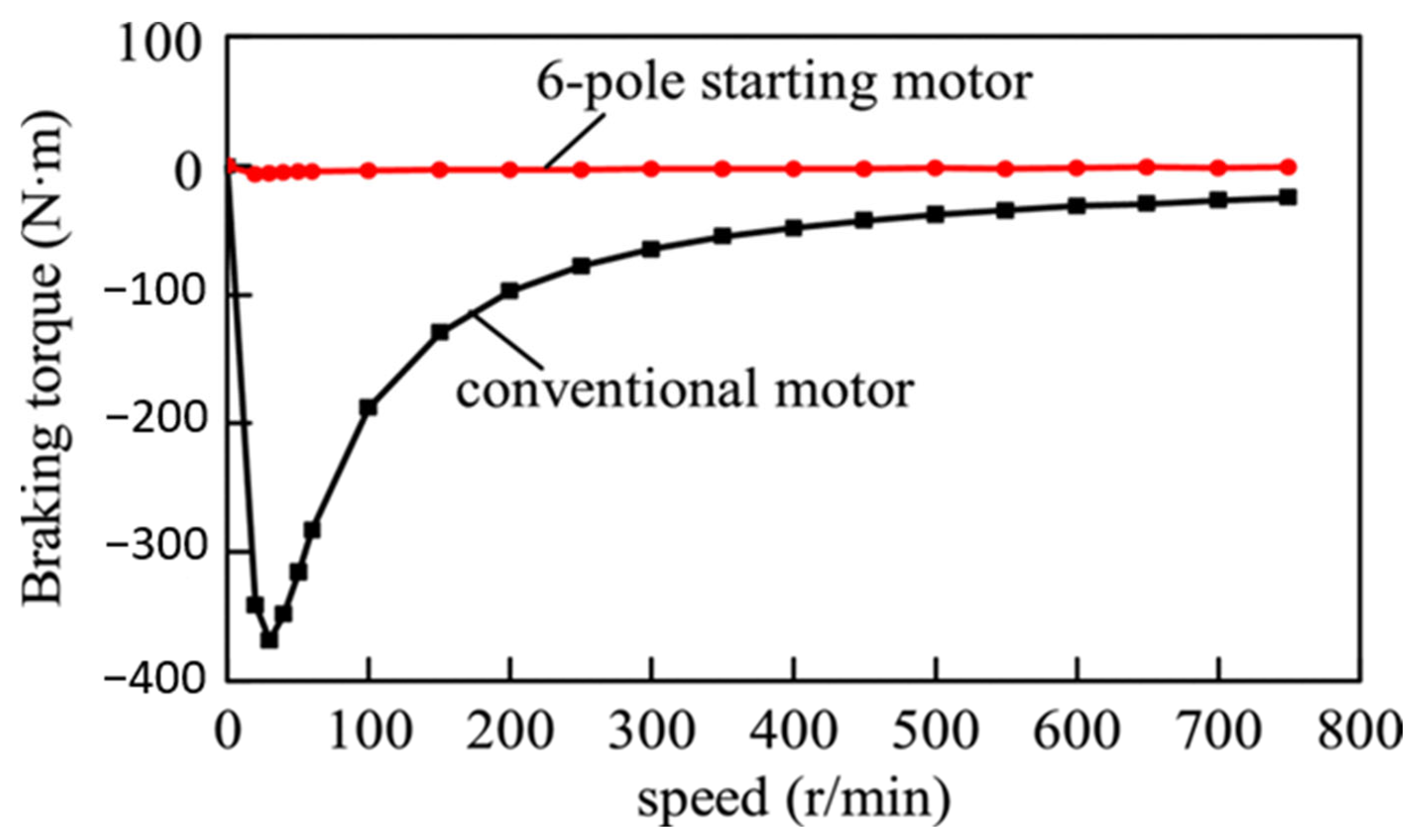
One promising solution involves pole-changing configurations, exemplified by a 6/8-pole LSPMSM introduced in studies [43,44,45,46]. As illustrated in Figure 36, which shows the motor geometry, this motor employs a stator winding that operates in a 6-pole mode during startup and transitions to an 8-pole mode for synchronous operation. The initial mismatch between stator and rotor pole numbers prevents flux interaction with the permanent magnets, thereby eliminating braking torque and reducing harmonic disturbances during startup, as shown in Figure 37. Once the rotor reaches the appropriate speed, the 6-pole winding is deactivated, and the 8-pole winding is engaged to achieve synchronization. Experimental results confirm improved startability and synchronization capacity compared to conventional 8-pole designs. Conceptually, two implementation methods can be considered: using separate windings or a single dual-speed winding. While the dual-winding setup allows targeted optimization for both transient and steady-state operation, it increases size and manufacturing cost. The single-winding alternative is more compact but limits design flexibility, potentially affecting both efficiency and current density. Moreover, achieving sufficient locked rotor and pull-up torque remains a challenge due to the limited torque-producing capability of the rotor cage during the 6-pole startup phase.

4.3.2. Composite Solid Rotor

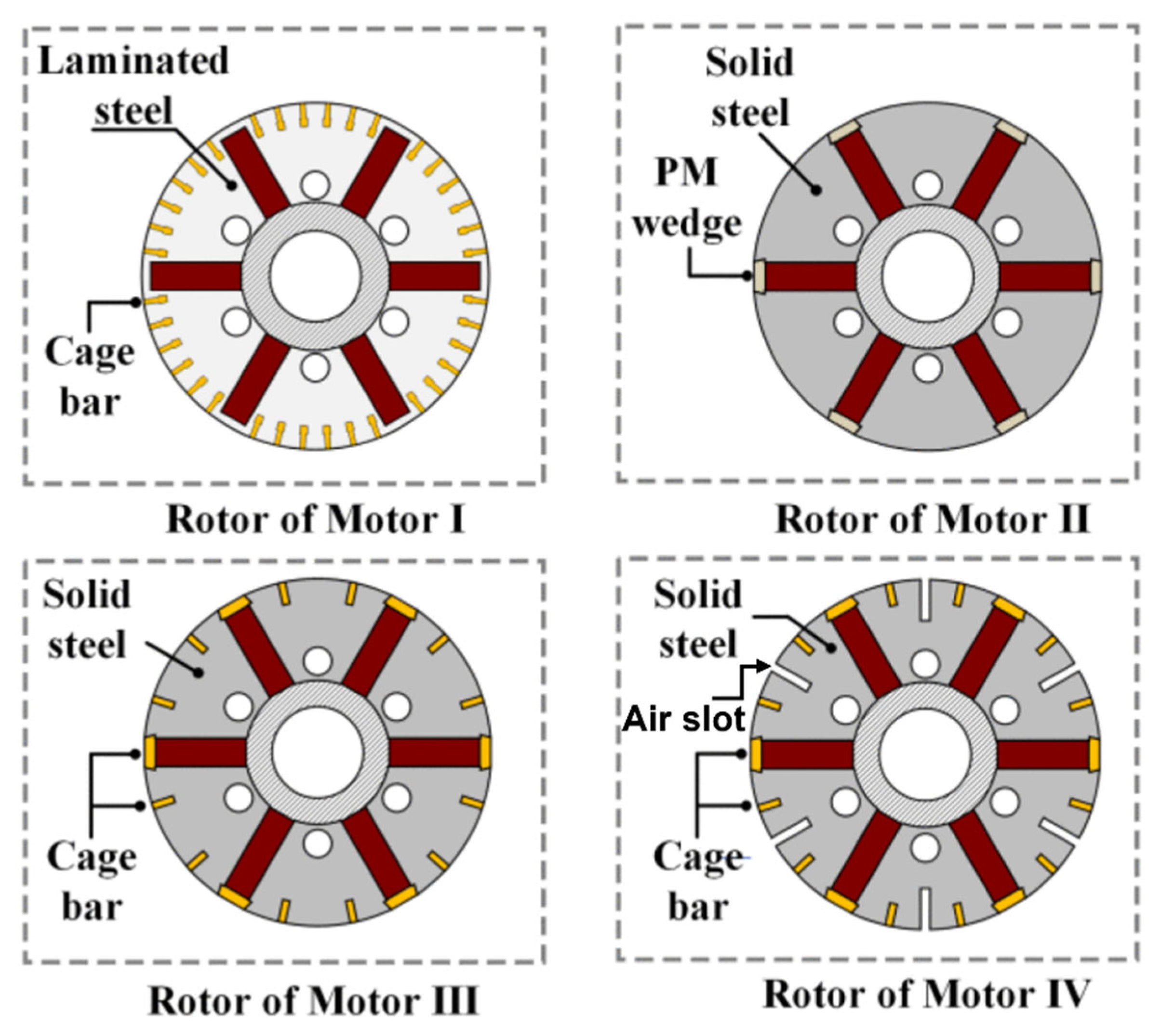
Composite solid rotors represent another innovative direction in LSPMSM design, as investigated in several studies [47,48,49,50,51]. Figure 38 illustrates four motor configurations used to evaluate this concept. The first case represents a conventional laminated rotor with a squirrel cage. In the second configuration, the laminated core is replaced by a solid steel rotor without a cage, resulting in a block-type rotor. The third case incorporates a squirrel cage into this solid steel rotor, while the fourth configuration adds air slots on the rotor surface. These progressive modifications highlight the role of rotor geometry and material structure in influencing performance.
The final configuration combining both a squirrel cage and surface air slots demonstrates the most effective balance between asynchronous starting and synchronization capability. As shown in Figure 39, this rotor structure significantly increases induction torque both at high slip (during startup) and at low slip (near synchronism). The solid steel core promotes strong eddy current generation, especially at large slips, which enhances torque during the early stages of acceleration. The embedded squirrel cage further improves torque across the entire slip range by reducing rotor impedance and reinforcing induction torque. Additionally, the air slots milled into the rotor surface alter the current distribution under small-slip conditions, increasing the effective penetration depth of eddy currents and thus raising the induction torque in the critical low-slip region where synchronization occurs. While the full slip profile of Motor IV is not shown, its behavior closely follows that of Motor III during large-slip conditions, with improved performance observed in the low-slip region (Figure 39b), confirming improved synchronization capability. The designed motor, rated at 355 kW, achieved a peak efficiency of 97.3% and a power factor of 0.89, demonstrating its industrial viability and high performance.

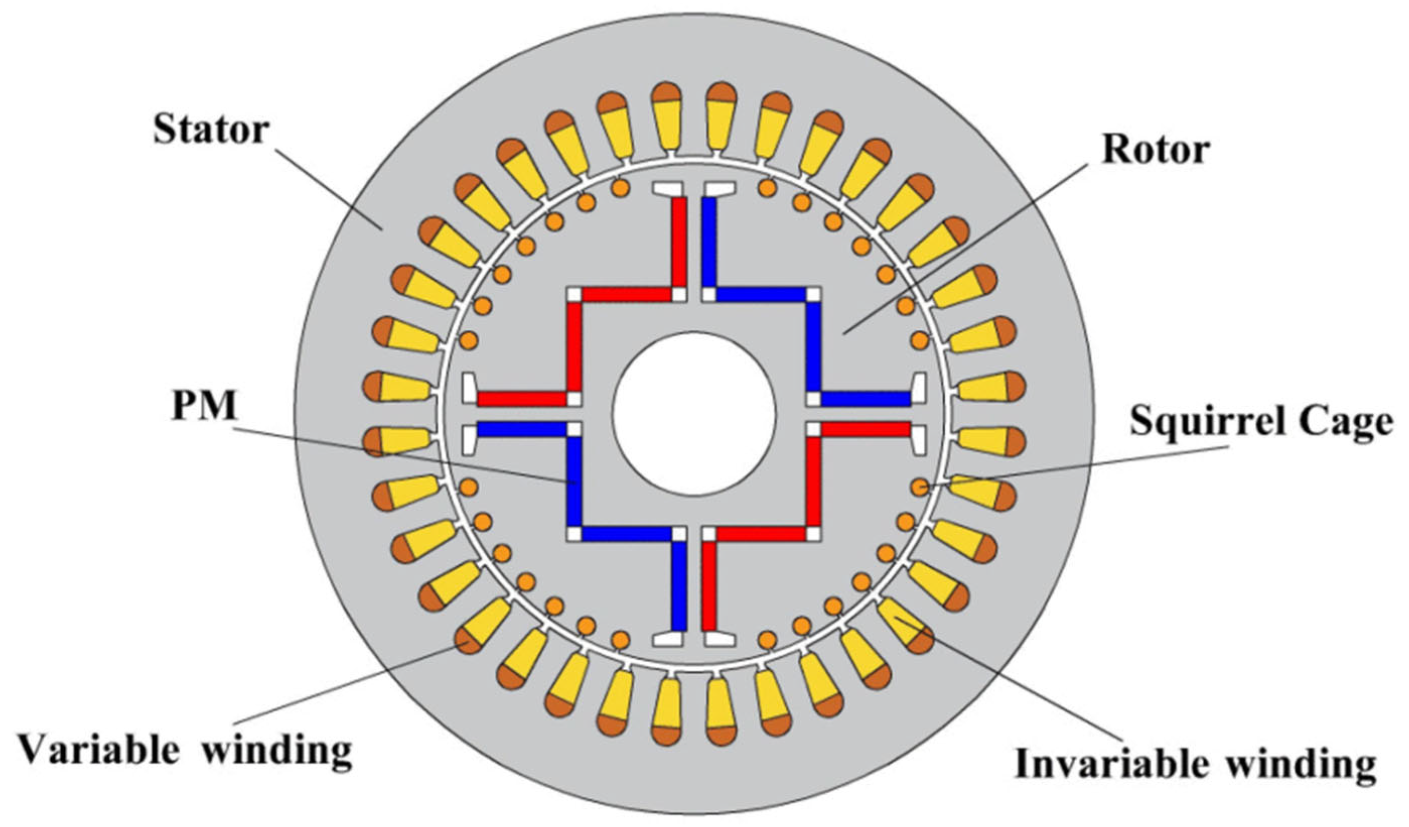
4.3.3. Winding Reconfiguration Technique

The winding reconfiguration technique represents another promising approach to performance enhancement in LSPMSMs [52,53]. These systems utilize switching mechanisms that reconfigure the stator winding between startup and steady-state operation. Figure 40 presents the motor geometry, highlighting a stator composed of two distinct winding types: variable and invariable windings. The invariable winding is not connected during startup, resulting in fewer turns per phase and thus allowing higher current and increased asynchronous torque. This design enables two primary strategies: coil-turns-changing, which increases asynchronous torque by reducing the number of turns during startup, and pole-changing, which mitigates permanent magnet braking torque by altering the stator’s effective pole pair count. These methods, when applied together, improve average starting torque without compromising steady-state performance.
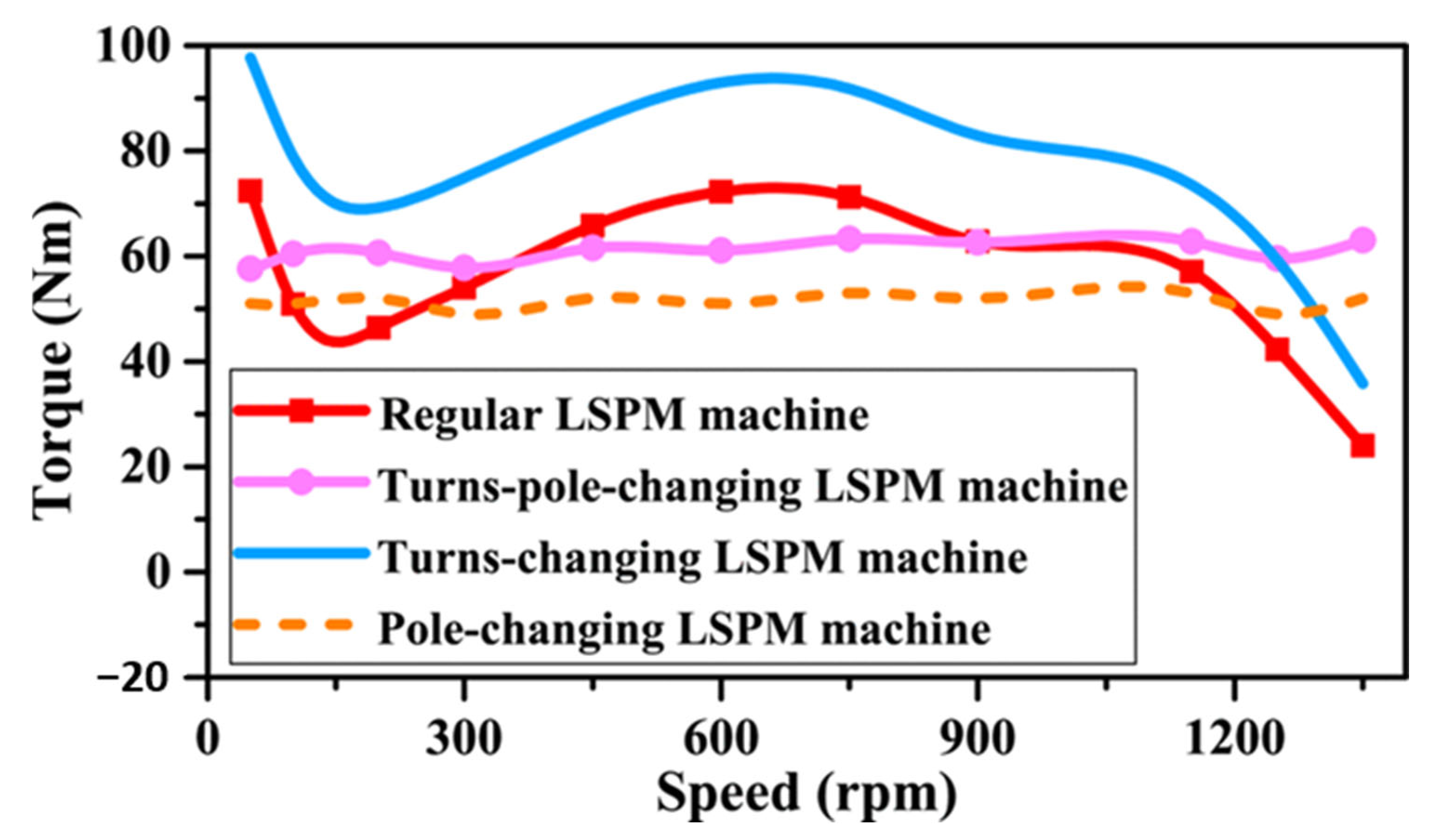
Figure 41 illustrates the effectiveness of different winding configurations in enhancing both starting torque and synchronization capability. The regular LSPM machine serves as the baseline, showing a variable torque profile with noticeable dip at low speeds caused by permanent magnet braking effects, which hinder both starting torque and synchronization. The pole-changing LSPM machine improves this behavior by reducing the effective pole pair count during startup, thereby eliminating braking torque; however, it does not significantly enhance asynchronous torque, resulting in a relatively flat but low torque curve. The turns-changing LSPM machine achieves much higher starting torque, especially in the mid-speed range, by reducing the number of stator turns, which increases current and improves induction torque. Finally, the turns-pole-changing LSPM machine combines both techniques, offering a balanced solution: the turns-changing technique increases asynchronous torque by raising stator current, while the pole-changing reduces braking torque but also decreases cage torque due to the lower number of poles. As a result, the overall torque is enhanced compared to the pole-changing configuration, with performance falling between that of the turns-changing and pole-changing machines. This combined strategy provides an effective trade-off between improved starting performance and reliable synchronization, underscoring the value of reconfigurable winding techniques for advanced LSPMSM designs.

4.3.4. Delta-Wye Winding Configuration

Another technique based on a similar principle is the delta-wye winding configuration [25]. While the reconfiguration method boosts flux by reducing the number of turns to allow higher current, the delta-wye approach increases flux by raising the voltage applied to each phase. This is achieved by energizing a stator winding, normally connected in wye (star), in a delta connection—resulting in approximately 73% higher stator flux. The increased flux enhances torque during startup, aiding synchronization under high load or inertia. However, the associated higher starting inrush current, which is not desired in motor applications, can lead to torque transients and increased mechanical stress compared to an induction motor counterpart.
Table 2 presents a summary of different LSPMSM configurations, highlighting their key design features and performance characteristics.
Table 3 summarizes key design features, advantages, and drawbacks of selected innovative topologies developed to enhance the starting and synchronization performance of LSPMSMs.

5. Industrial Adoption and Economic Viability of LSPMSMs

5.1. Industrial Applications and Commercial Models

Table 4 provides an overview of various commercially developed Line-Start Permanent Magnet Synchronous Motors (LSPMSMs), all meeting the IE4 efficiency class. The applications are seen to range from air conditioning and refrigeration to lifting and material handling. The SynchroVERT series by Bharatbijlee [54], ranging from 1.5 to 45 kW, and the WQuattro series by WEG [55], covering 0.37 to 7.5 kW, are designed for high-efficiency applications, such as pumps and fans. The DRU.J series from SEW Eurodrive [56], with a power range of 0.25 to 4 kW, is employed in constant-speed textile machinery. SISME [57] offers LSPMSM-based compressors with power ratings from 1.86 to 44.7 kW, targeting refrigeration and air-conditioning systems. Reuland Electric [58] manufactures LSPMSMs up to 37 kW, serving heavy-duty industrial sectors, including hoists, cranes, elevators, and conveyors. These examples indicate that several leading companies have begun to explore and develop LSPMSMs, recognizing their potential for high efficiency and suitability across a wide range of industrial applications.

5.2. Economic Comparison with IMs

The economic viability of Line-Start Permanent Magnet Synchronous Motors (LSPMSMs) is a key factor supporting their growing adoption across industrial applications. A comparative analysis with conventional Squirrel-Cage Induction Motors (SCIMs), based on IEC efficiency classes and total cost of ownership, reveals compelling long-term benefits. Table 5, adapted from Almeida et al. [15], presents a case study based on a standard 7.5 kW, four-pole motor.
While the initial cost of an IE4-class LSPMSM (EUR 764) is significantly higher than that of an IE2-class SCIM (EUR 328), the superior efficiency of the LSPMSM (93.5% vs. 89.0%) translates into notable energy savings. Specifically, the LSPMSM saves approximately EUR 153 per year in electricity costs compared to the IE2 motor. The simple payback period can be calculated as follows:
P a y b a c k   P e r i o d   years =   E x t r a   I n i t i a l   C o s t A n n u a l   E n e r g y   S a v i n g s
Although the IE3-class SCIM offers a shorter payback period of 0.5 years, it delivers lower annual savings (EUR 97.2) and reduced long-term efficiency gains.
In continuous-duty applications, such as pumps, fans, and compressors, the cumulative savings achieved with LSPMSMs over the motor’s lifespan are substantial. These benefits extend beyond reduced electricity consumption to include decreased lifecycle energy usage and lower carbon emissions, aligning with current regulatory requirements and sustainability objectives.
A study by Kazakbaev et al. [59] further reinforces the economic case by accounting for cable losses in lifecycle assessments. In a 4 kW pump application, the total energy cost savings over the motor’s lifetime increased from EUR 2626 to EUR 4020 when cable losses were included. This highlights the importance of evaluating system-level energy performance, not just motor efficiency in isolation.
Additional system-level benefits further enhance the economic appeal of LSPMSMs. Their lower current demand permits the use of smaller-rated transformers and Variable Frequency Drives (VFDs), thereby reducing infrastructure and installation costs. Moreover, the reduced operating temperatures of LSPMSMs contribute to the extended lifespan of critical components, such as windings, insulation, and bearings, ultimately lowering maintenance requirements and improving overall system reliability [5].
Beyond the motor itself, the deployment of LSPMSMs can enhance overall system performance. In applications such as pumping systems, their synchronous operation often leads to increased flow output compared to induction motors due to the elimination of slip and operation at synchronous speed. This improved performance is especially beneficial when higher flow is needed. In retrofit cases where the original flow rate must be maintained, minor adjustments such as resizing the impeller can help fine-tune the system. This ensures the energy-saving potential of LSPMSMs is fully utilized while meeting the specific demands of the application.
When integrated with VFDs, LSPMSMs offer additional flexibility by supporting high-inertia loads that may exceed the limitations of Direct-On-Line (DOL) startup. The embedded squirrel cage enables reliable operation under scalar control (V/f) without requiring position feedback, making LSPMSMs suitable for variable-speed applications. For instance, a 75 HP LSPMSM operating under variable-speed conditions was shown to achieve annual energy savings exceeding USD 2200 under typical industrial operating profiles [5].
Despite their higher initial cost, LSPMSMs offer a robust return on investment through substantial energy savings, lower operating costs, and enhanced system reliability. Their compatibility with evolving energy regulations, combined with superior performance under both fixed- and variable-speed applications, makes them a viable and economically efficient solution for modern industrial systems.

6. Conclusions

This review has explored the performance characteristics, historical evolution, and design innovations of Line-Start Permanent Magnet Synchronous Motors (LSPMSMs), emphasizing their growing potential as energy-efficient replacements for conventional induction motors in fixed-speed industrial applications. By combining Direct-On-Line (DOL) starting capability with permanent magnet excitation, LSPMSMs offer a compelling blend of simplicity, high efficiency, and operational reliability—qualities that are increasingly important in the context of global energy conservation and climate goals.
Despite these advantages, LSPMSMs still face practical challenges related to synchronization under high-inertia loads, starting current compliance, and manufacturability. While improvements in rotor topology, cage resistance, and magnet configuration have yielded notable gains, no universally viable design has yet emerged that satisfies the same industrial constraints as induction motors.
To become a practical drop-in replacement, LSPMSMs must synchronize under standardized starting current limits, support comparable critical load inertia, and achieve IE5-class efficiency within the same frame size. Achieving this requires integrated design approaches that simultaneously address electromagnetic performance, thermal behavior, mechanical robustness, and, where necessary, the use of a drive.
LSPMSMs remain a promising yet evolving motor technology. The research community is still seeking a practical and easily manufacturable solution to these challenges, which have persisted for over 70 years.

Author Contributions

Conceptualization, Y.O.L., R.R., and C.C.; methodology, Y.O.L., R.R., and C.C.; validation, Y.O.L., R.R., and C.C.; formal analysis, Y.O.L., R.R., and C.C.; investigation, Y.O.L., R.R., and C.C.; resources, Y.O.L., R.R., and C.C.; data curation, Y.O.L., R.R., and C.C.; writing—original draft preparation, Y.O.L., R.R., and C.C.; writing—review and editing, Y.O.L., R.R., and C.C.; visualization, Y.O.L., R.R., and C.C. All authors have read and agreed to the published version of the manuscript.

Funding

Project “Hybrid Inverter Drive” financed by Xjenza Malta through the FUSION: R&I Technology Development Programme.

Conflicts of Interest

The authors declare no conflicts of interest.

References

  1. IEA. World Energy Outlook 2024. Available online: https://www.iea.org/reports/world-energy-outlook-2024 (accessed on 1 April 2024).
  2. de Souza, D.F.; da Silva, P.P.F.; Sauer, I.L.; de Almeida, A.T.; Tatizawa, H. Life cycle assessment of electric motors—A systematic literature review. J. Clean. Prod. 2024, 456, 142366. [Google Scholar] [CrossRef]
  3. Isfahani, A.H.; Vaez-Zadeh, S. Line start permanent magnet synchronous motors: Challenges and opportunities. Energy 2009, 34, 1755–1763. [Google Scholar] [CrossRef]
  4. Ganesan, A.U.; Chokkalingam, L.N. Review on the evolution of technology advancements and applications of line-start synchronous machines. IET Electr. Power Appl. 2019, 13, 1–16. [Google Scholar] [CrossRef]
  5. McElveen, R.F.; Holub, R.; Martin, W.E. Replacing induction motors with caged rotor permanent magnet motors: Application considerations & cost analysis. In Proceedings of the 2017 Petroleum and Chemical Industry Technical Conference (PCIC), Calgary, AB, Canada, 18–20 September 2017; pp. 435–442. [Google Scholar]
  6. Miller, T. Synchronization of line-start permanent-magnet ac motors. IEEE Trans. Power Appar. Syst. 1984, PAS-103, 1822–1828. [Google Scholar] [CrossRef]
  7. Palangar, M.F.; Soong, W.L.; Bianchi, N.; Wang, R.-J. Design and optimization techniques in performance improvement of line-start permanent magnet synchronous motors: A review. IEEE Trans. Magn. 2021, 57, 1–14. [Google Scholar] [CrossRef]
  8. IPCC. AR6 Synthesis Report: Climate Change 2023. Available online: https://www.ipcc.ch/report/ar6/syr/ (accessed on 1 April 2024).
  9. Energy Institute. Statistical Review of World Energy 2024. Available online: https://www.energyinst.org/statistical-review (accessed on 1 April 2024).
  10. Ember. Global Electricity Review 2024. Available online: https://ember-energy.org/latest-insights/global-electricity-review-2024/ (accessed on 1 April 2024).
  11. IEA. 4E: Policy Guidelines for Motor Driven Units 2016. Available online: https://www.iea-4e.org/projects/the-motor-driven-unit-policy-guidelines/ (accessed on 1 April 2024).
  12. Lu, S.-M. A review of high-efficiency motors: Specification, policy, and technology. Renew. Sustain. Energy Rev. 2016, 59, 1–12. [Google Scholar] [CrossRef]
  13. IEC 60034-30; Rotating Electrical Machines—Part 30-3: Efficiency Classes of High Voltage AC Motors (IE-Code). International Electrotechnical Commission (IEC): Geneva, Switzerland, 2024.
  14. de Almeida, A.T.; Fong, J.; Falkner, H.; Bertoldi, P. Policy options to promote energy efficient electric motors and drives in the EU. Renew. Sustain. Energy Rev. 2017, 74, 1275–1286. [Google Scholar] [CrossRef]
  15. De Almeida, A.T.; Ferreira, F.J.; Quintino, A. Technical and economical considerations on super high-efficiency three-phase motors. In Proceedings of the 48th IEEE Industrial & Commercial Power Systems Conference, Louisville, KY, USA, 20–24 May 2012; pp. 1–13. [Google Scholar]
  16. EMSA MEPS MAP Export. 2024. Available online: https://www.iea-4e.org/wp-content/uploads/2019/10/emsa-meps-export-v2.pdf (accessed on 1 April 2024).
  17. Rabbi, S.F.; Rahman, M.A. Critical criteria for successful synchronization of line-start IPM motors. IEEE J. Emerg. Sel. Top. Power Electron. 2013, 2, 348–358. [Google Scholar] [CrossRef]
  18. Libert, F.; Soulard, J.; Engstrom, J. Design of a 4-pole line start permanent magnet synchronous motor. In Proceedings of the ICEM 2002: 15th International Conference on Electrical Machines, Brugge, Belgium, 25–28 August 2002; pp. 25–28. [Google Scholar]
  19. NEMA SM 1; Guide to General-Purpose Synchronous Motors Without Excited Rotor Windings. National Electrical Manufacturers Association (NEMA): Rosslyn, VA, USA, 2021.
  20. McElveen, R.; Melfi, M.; Daugherty, R. Line start permanent magnet motors-Starting, standards and application guidelines. In Proceedings of the 2014 IEEE Petroleum and Chemical Industry Technical Conference (PCIC), San Francisco, CA, USA, 8–10 September 2014; pp. 129–139. [Google Scholar]
  21. Isfahani, A.H.; Vaez-zadeh, S. Rotor resistance for improved start-up performance of line-start permanent-magnet synchronous motors. In Proceedings of the 2018 IEEE Transportation Electrification Conference and Expo (ITEC), Long Beach, CA, USA, 13–15 June 2018; pp. 832–838. [Google Scholar]
  22. Jedryczka, C.; Wojciechowski, R.M.; Demenko, A. Finite element analysis of the asynchronous torque in LSPMSM with non-symmetrical squirrel cage winding. Int. J. Appl. Electromagn. Mech. 2014, 46, 367–373. [Google Scholar] [CrossRef]
  23. Isfahani, A.H.; Vaez-Zadeh, S. Effects of magnetizing inductance on start-up and synchronization of line-start permanent-magnet synchronous motors. IEEE Trans. Magn. 2010, 47, 823–829. [Google Scholar] [CrossRef]
  24. Wymeerschl, B.; De Belie, F.; Rasmussen, C.B.; Vandevelde, L. The effect of design considerations on the synchronization capability limits of line-start permanent-magnet synchronous motors. In Proceedings of the 2018 XIII International Conference on Electrical Machines (ICEM), Alexandroupoli, Greece, 3–6 September 2018; pp. 988–994. [Google Scholar]
  25. McElveen, R.F.; Budzynski, R.; Jarvinen, J.; Martin, W.E. Solving The Synchronization Problem of Line Start Permanent Magnet Motors. In Proceedings of the 2022 IEEE IAS Petroleum and Chemical Industry Technical Conference (PCIC), Denver, CO, USA, 26–29 September 2022; pp. 59–68. [Google Scholar]
  26. Merrill, F. Permanent magnet excited synchronous motors. Electr. Eng. 1955, 74, 143. [Google Scholar] [CrossRef]
  27. Cahill, D.P.M.; Adkins, B. The permanent-magnet synchronous motor. Proc. IEE-Part A Power Eng. 1962, 109, 483–491. [Google Scholar] [CrossRef]
  28. Binns, K.; Barnard, W. Novel design of self-starting synchronous motor. Proc. Inst. Electr. Eng. 1971, 118, 369–372. [Google Scholar] [CrossRef]
  29. Binns, K.; Barnard, W.; Jabbar, M. Hybrid permanent-magnet synchronous motors. Proc. Inst. Electr. Eng. 1978, 125, 203–208. [Google Scholar] [CrossRef]
  30. Binns, K.; Jabbar, M. High-field self-starting permanent-magnet synchronous motor. IEE Proc. B (Electr. Power Appl.) 1981, 128, 157–160. [Google Scholar] [CrossRef]
  31. Honsinger, V. The fields and parameters of interior type AC permanent magnet machines. IEEE Trans. Power Appar. Syst. 1982, PAS-101, 867–876. [Google Scholar] [CrossRef]
  32. Chalmers, B.; Hamed, S.; Baines, G. Parameters and performance of a high-field permanent-magnet synchronous motor for variable-frequency operation. IEE Proc. B (Electr. Power Appl.) 1985, 132, 117–124. [Google Scholar] [CrossRef]
  33. Knight, A.M.; McClay, C.I. The design of high-efficiency line-start motors. IEEE Trans. Ind. Appl. 2000, 36, 1555–1562. [Google Scholar] [CrossRef]
  34. Kurihara, K.; Rahman, M.A. High-efficiency line-start interior permanent-magnet synchronous motors. IEEE Trans. Ind. Appl. 2004, 40, 789–796. [Google Scholar] [CrossRef]
  35. Ding, T.; Takorabet, N.; Sargos, F.-M.; Wang, X. Design and analysis of different line-start PM synchronous motors for oil-pump applications. IEEE Trans. Magn. 2009, 45, 1816–1819. [Google Scholar] [CrossRef]
  36. Elistratova, V. Conception Optimale D’une Gamme de Moteurs Synchrones à Démarrage Direct à Haute Performance Energétique. Ph.D. Thesis, Université Lille Nord-de-France, Lille, France, 2015. [Google Scholar]
  37. Ghahfarokhi, M.M.; Aliabad, A.D.; Boroujeni, S.T.; Amiri, E.; Faradonbeh, V.Z. Analytical modelling and optimisation of line start LSPM synchronous motors. IET Electr. Power Appl. 2020, 14, 398–408. [Google Scholar] [CrossRef]
  38. Waheed, A.; Ro, J. Analytical modeling for optimal rotor shape to design highly efficient line-start permanent magnet synchronous motor. IEEE Access 2020, 8, 145672–145686. [Google Scholar] [CrossRef]
  39. Gwozdziewicz, M.; Zawilak, J. Induced pole permanent magnet synchronous motor. In Proceedings of the 2017 International Symposium on Electrical Machines (SME), Naleczow, Poland, 18–21 June 2017; pp. 1–4. [Google Scholar]
  40. Ugale, R.; Chaudhari, B. A new rotor structure for line start permanent magnet synchronous motor. In Proceedings of the 2013 International Electric Machines & Drives Conference, Chicago, IL, USA, 12–15 May 2013; pp. 1436–1442. [Google Scholar]
  41. Ugale, R.T.; Chaudhari, B.N. Performance enhancement of line start permanent magnet synchronous motor with a special consequent pole rotor. IEEE Trans. Energy Convers. 2020, 36, 1972–1982. [Google Scholar] [CrossRef]
  42. Lyskawinski, W.; Jedryczka, C.; Szelag, W. Influence of magnet and cage shape on properties of the line start synchronous motor with powder hybrid rotor. In Proceedings of the 2017 International Symposium on Electrical Machines (SME), Naleczow, Poland, 18–21 June 2017; pp. 1–6. [Google Scholar]
  43. Zhao, W.; Tian, M.; Wang, X.; Sun, Y. Analysis of the synchronization process and the synchronization capability for a novel 6/8-pole changing LSPMSM. IEEE Trans. Magn. 2020, 56, 7507806. [Google Scholar] [CrossRef]
  44. Tian, M.; Wang, X.; Wang, D.; Zhao, W.; Li, C. A novel line-start permanent magnet synchronous motor with 6/8 pole changing stator winding. IEEE Trans. Energy Convers. 2018, 33, 1164–1174. [Google Scholar] [CrossRef]
  45. Lin, M.; Li, D.; Zhao, Y.; Ren, X.; Qu, R. Comparison of different types of pole-changing line-start permanent magnet motors. In Proceedings of the 2018 XIII International Conference on Electrical Machines (ICEM), Alexandroupoli, Greece, 3–6 September 2018; pp. 2051–2057. [Google Scholar]
  46. Tian, M.; Wang, X.; Li, G. Line-start permanent magnet synchronous motor starting capability improvement using pole-changing method. In Proceedings of the 11th Conference on Industrial Electronics and Applications, Hefei, China, 5–7 June 2016. [Google Scholar]
  47. Yan, B.; Wang, X.; Yang, Y. Parameters determination and dynamic modelling of line-start permanent-magnet synchronous motor with a composite solid rotor. IET Electr. Power Appl. 2019, 13, 17–23. [Google Scholar] [CrossRef]
  48. Yan, B.; Wang, X.; Yang, Y. Starting performance improvement of line-start permanent-magnet synchronous motor using composite solid rotor. IEEE Trans. Magn. 2017, 54, 7400504. [Google Scholar] [CrossRef]
  49. Yan, B.; Wang, X.; Yang, Y. Comparative parameters investigation of composite solid rotor applied to line-start permanent-magnet synchronous motors. IEEE Trans. Magn. 2018, 54, 8206305. [Google Scholar] [CrossRef]
  50. Yan, B.; Yang, Y.; Wang, X. Design of a large capacity line-start permanent magnet synchronous motor equipped with hybrid salient rotor. IEEE Trans. Ind. Electron. 2020, 68, 6662–6671. [Google Scholar] [CrossRef]
  51. Yang, Y.; Yan, B.; Wang, X. Dynamic Model of a Line-Start Permanent Magnet Synchronous Motor Equipped with Hybrid Rotor. IEEE Trans. Transp. Electrif. 2023, 10, 2974–2987. [Google Scholar] [CrossRef]
  52. Lin, M.; Li, D.; Zhao, Y.; Ren, X.; Qu, R. Improvement of starting performance for line-start permanent magnet motors by winding reconfiguration. IEEE Trans. Ind. Appl. 2020, 56, 2441–2450. [Google Scholar] [CrossRef]
  53. Lin, M.; Li, D.; Zhao, Y.; Ren, X.; Qu, R. Line-start permanent magnet motors with variable coil turns. In Proceedings of the 2018 XIII International Conference on Electrical Machines (ICEM), Alexandroupoli, Greece, 3–6 September 2018; pp. 2212–2218. [Google Scholar]
  54. Biljee, B. SynchroVERT® IE4 Motors. Available online: https://www.bharatbijlee.com/electric-motors/product-range/synchrovert-ie4-motors/ (accessed on 26 April 2025).
  55. WEG. WQuattro. Available online: https://www.weg.net/catalog/weg/RS/en/Electric-Motors/Low-Voltage-IEC-Motors/Three-Phase/W22-Quattro/WQuattro/p/MKT_WMO_TEXT_IMAGE_3PHASE_TEFC_WQUATTRO (accessed on 1 April 2025).
  56. SEW Eurodrive. DR…J Synchronous Motors (LSPM Technology). Available online: https://www.sew-eurodrive.es/products/motors/ac_motors/ac_motors_drj_with_lspm_technology/ac_motors_drj_with_lspm_technology.html (accessed on 1 April 2025).
  57. SISME. LSPM Refrigeration Compressor Motors. Available online: https://sisme.it/en/air-conditioning-and-refrigeration-motors/motors-for-refrigeration-compressors/ (accessed on 26 March 2025).
  58. Reuland. Line Start Permanent Magnet Motors. Available online: https://www.reuland.com/line-start-permanent-magnet-motors (accessed on 1 April 2025).
  59. Kazakbaev, V.; Prakht, V.; Dmitrievskii, V.; Oshurbekov, S.; Golovanov, D. Life cycle energy cost assessment for pump units with various types of line-start operating motors including cable losses. Energies 2020, 13, 3546. [Google Scholar] [CrossRef]
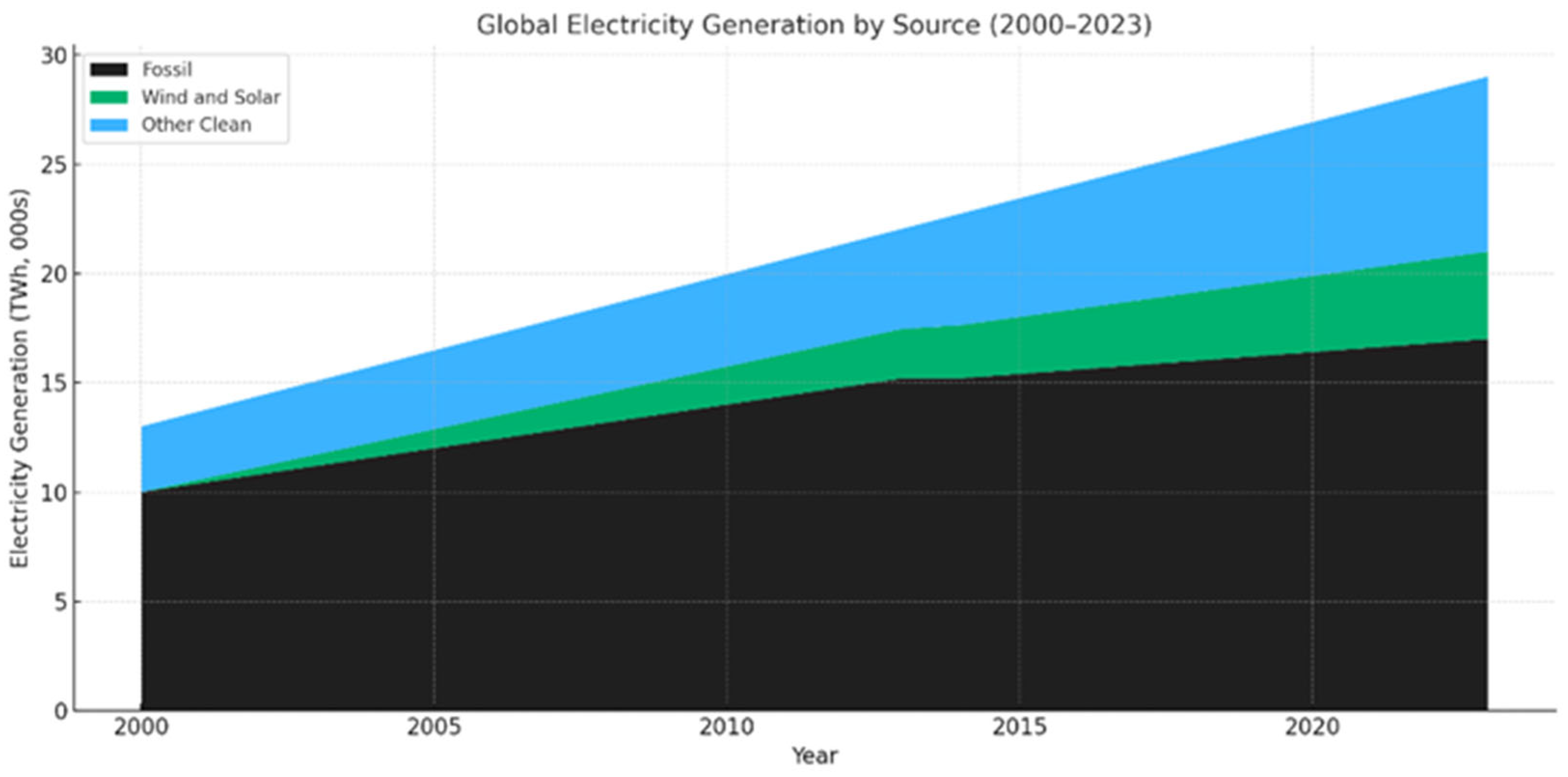
Figure 1. Global electricity generation by source (2024) [10].
Energies 18 04545 g001
Figure 2. Motor electricity use by application (%) [11].
Energies 18 04545 g002
Figure 3. Efficiency classification for fixed-speed motors [15].
Energies 18 04545 g003
Figure 4. Rotor geometry of the LSPMSM showing the orientation of the direct (d) and quadrature (q) axes.
Energies 18 04545 g004
Figure 5. d–q axis equivalent circuit of a Line-Start Permanent Magnet Synchronous Motor (LSPMSM).
Energies 18 04545 g005
Figure 6. Torque–speed characteristics of a line-start PM motor [17].
Energies 18 04545 g006
Figure 7. (a) Synchronous torque vs. load angle; (b) pole slipping behavior during LSPMSM synchronization [17].
Energies 18 04545 g007
Figure 8. Startup speed–time profiles of LSPMSM under different design scenarios [18].
Energies 18 04545 g008
Figure 9. Critical inertia as a function of load torque for constant and dynamic load conditions [17].
Energies 18 04545 g009
Figure 10. Effect of rotor cage resistance on resultant torque in LSPMSMs [21].
Energies 18 04545 g010
Figure 11. Startup speed characteristics of LSPMSM under high-inertia load conditions [21].
Energies 18 04545 g011
Figure 12. Comparison of rotor cage geometries: (a) symmetrical cage; (b) asymmetrical cage; (c) reference induction motor [17].
Energies 18 04545 g012
Figure 13. Different magnet sizes: (a) thin magnet; (b) thick magnet.
Energies 18 04545 g013
Figure 14. Variation in critical inertia with supply voltage in LSPMSMs [24].
Energies 18 04545 g014
Figure 15. Torque–speed characteristics during direct-on-line startup: (a) LSPMSM; (b) induction motor [20].
Energies 18 04545 g015
Figure 16. Synchronization behavior of IM, LSPMSM, and LSSynRM motors [4].
Energies 18 04545 g016
Figure 17. Phase-A current profile under full load for IM, LSPMSM, and LSSynRM [4].
Energies 18 04545 g017
Figure 18. Comparison of total losses and efficiency across different output power [4].
Energies 18 04545 g018
Figure 19. Efficiency and power factor comparison between LSPMSM and induction motors: (a) efficiency; (b) power factor [5]. Note: The original label “CRPM” was changed to “LSPMSM” for consistency with the terminology used throughout this review.
Energies 18 04545 g019
Figure 20. Structural and electromagnetic overview of the original Permasyn motor by Merrill (1955): (a) flux distribution diagram; (b) one-piece permanent magnet casting [26].
Energies 18 04545 g020
Figure 21. Rotor design by Cahill and Adkins using Ticonal magnets (1962) [27].
Energies 18 04545 g021
Figure 22. Early rotor configurations: (a) segmented rotor; (b) Binns and Barnard motor [28].
Energies 18 04545 g022
Figure 23. Rotor topologies by Binns, Barnard, and Jabbar: (a) surface-inset; (b) interior permanent magnet motor [29].
Energies 18 04545 g023
Figure 24. Four-pole non-radial axis magnet rotor by Binns and Jabbar [30].
Energies 18 04545 g024
Figure 25. Rotor geometries proposed by Honsinger for multi-pole machines [31].
Energies 18 04545 g025
Figure 26. Rotor geometries proposed by Miller for LSPMSMs [6].
Energies 18 04545 g026
Figure 27. Chalmers rotor with radial samarium–cobalt magnets for VFD operation [32].
Energies 18 04545 g027
Figure 28. Cross-section of one pole of curved magnet LSPM rotor by Knight and McClay [33].
Energies 18 04545 g028
Figure 29. Interior PM rotor with deep bars and flux barriers by Rahman [34].
Energies 18 04545 g029
Figure 30. Three rotor designs for oil-pump applications: (a) surface-mounted magnets; (b) solid rotor with azimuthal interior magnets; (c) U-shaped embedded magnets [35].
Energies 18 04545 g030
Figure 31. Comparative rotor topologies: (a) spoke-type; (b) series-type; (c) V-shaped configurations [36].
Energies 18 04545 g031
Figure 32. Dual-layer U-shaped magnet rotor optimized via genetic algorithm [37].
Energies 18 04545 g032
Figure 33. Convex-profile LSPMSM [38].
Energies 18 04545 g033
Figure 34. Induced-pole rotor topology [39].
Energies 18 04545 g034
Figure 35. Hybrid powder-composite rotor using SMC materials and NdFeB magnets.
Energies 18 04545 g035
Figure 36. 6/8-pole switching stator winding configuration in LSPMSM [43].
Energies 18 04545 g036
Figure 37. Braking torque elimination in a pole-changing stator design [44].
Energies 18 04545 g037
Figure 38. Rotor cross-sections of four different motor configurations (Motors I–IV) [50].
Energies 18 04545 g038
Figure 39. Torque-slip curves of different motor types: (a) Motors I–III, (b) Motors III and IV.
Energies 18 04545 g039
Figure 40. Turns-changing winding structure for enhanced startup torque [52].
Energies 18 04545 g040
Figure 41. Comparative starting torque of regular and reconfigurable winding designs [52].
Energies 18 04545 g041
Table 1. Minimum Energy Performance Standards (MEPS) for electric motors by country [16].
Motors MEPS LevelsCountry/Jurisdiction
IE3Brazil, Canada, European Union, Japan, Korea, Mexico, Colombia, Saudi Arabia, China, Singapore, Switzerland, Chinese Taipei, Turkey, United States
IE2Australia, Chile, Ecuador, India, New Zealand
Table 2. Overview of the performance of different Line-Start Permanent Magnet Synchronous Motors (LSPMSMs).
TopologyOutput Power (kW)T_avg (Nm)Speed (rpm)Power FactorEfficiency
6/8 Pole-changing LSPMSM [43]30382NANANA
Composite solid rotor [50]3553390NANANA
Turns-changing LSPMSM [52]7.5NANANANA
Induced pole rotor [39]212.715000.9588.2
Convex-profile LSPMSM [38]7.51936000.9194.7
Curve-shaped powder material PM [42]3.452215000.9593
Double-layer U-shaped PM LSPMSM [37]NANA1500NANA
Table 3. Key features and trade-offs of innovative LSPMSM topologies.
TopologyKey FeatureMain AdvantageDrawback
6/8 Pole-Changing StatorSwitches pole pairs between startup and synchronous modeEliminates braking torque, improves startupRequires dual winding and switching mechanism
Composite Solid RotorSolid rotor with embedded cage and surface air slotsHigh torque and strong synchronization capabilityIncreased rotor weight and manufacturing complexity
Turns-Changing WindingVaries coil turns between startup and steady-state modesBoosts starting torqueNeeds switching control; more complex stator
Table 4. Commercial LSPMSM models, efficiency class, and typical applications.
LSPMSM MotorEfficiencyPowerApplication
SynchroVERTIE4 class1.5–45 kWPump or Fan [54]
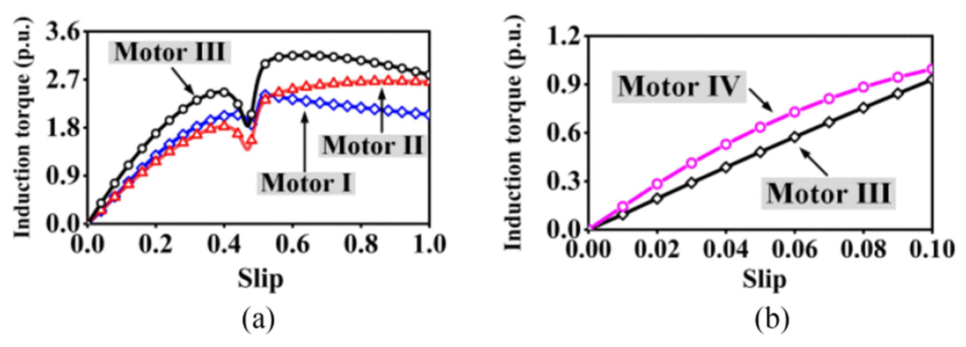
WQuattroIE4 class0.37–7.5 kWReplacement of SCIM in Pumps or Fans [55]
DRU.J seriesIE4 class0.25–4 kWMaterial Supply in Textile Machinery [56]
LSPMSM compressorsIE4 class1.86–44.7 kWIndustrial and domestic refrigeration, Air conditioning [57]
Reuland LSPMSMIE4 classUp to 37 KWHoists, cranes, elevators, mixers, and conveyors [58]
Table 5. Economic comparison between SCIM and LSPMSM technologies.
IEC ClassIE1IE2IE3IE4
Motor TechnologySCIMSCIMSCIMLSPM
Motor Price with 40% Discount (EUR)..328378764
Price Difference Compared to IE2 SCIM (EUR)....50386
Motor Efficiency (%)87.089.091.593.5
Consumption by Replacing IE2-Class Motor (kWh/year)51,98350,81549,42648,629
Energy Savings by Replacing IE2-Class Motor (kWh/year)−1168013882186
Energy Savings by Replacing IE2-Class Motor (EUR/year)−81.8097.2153.0
Simple Payback Time (year)....0.52.8
Disclaimer/Publisher’s Note: The statements, opinions and data contained in all publications are solely those of the individual author(s) and contributor(s) and not of MDPI and/or the editor(s). MDPI and/or the editor(s) disclaim responsibility for any injury to people or property resulting from any ideas, methods, instructions or products referred to in the content.