Article

Research on Active Defense System for Transformer Early Fault Based on Fiber Leakage Magnetic Field Measurement

1
China Yangtze Power Co., Ltd., Wudongde Hydroelectric Power Plant, Kunming 650000, China
2
College of Electrical Engineering, Shanghai University of Electric Power, Shanghai 200000, China
*
Author to whom correspondence should be addressed.
Energies 2025, 18(17), 4497; https://doi.org/10.3390/en18174497
Submission received: 28 July 2025 / Revised: 5 August 2025 / Accepted: 19 August 2025 / Published: 24 August 2025

Abstract

In the early faults of transformer windings, there are obvious variation characteristics of the spatial leakage magnetic field. Taking the leakage magnetic field as the fault characteristic quantity can establish an active defense system for transformer defects and faults, thereby increasing the service life of the equipment. However, the installation method of the optical fiber leakage magnetic field sensor, the principle of leakage magnetic field protection, the research and development of the protection device, and the dynamic model testing of the protection device are all key links in realizing the leakage magnetic field monitoring and active defense system. This paper first analyzes the symmetry of the winding leakage magnetic field, proposes invasive and non-invasive installation methods for optical fiber sensors based on different application scenarios, presents the principle of leakage magnetic field differential protection, and develops a protection device. The feasibility of the protection scheme proposed in this paper was verified through dynamic model experiments, and the early fault active defense system was put into actual on-site operation.

1. Introduction

As key equipment for power conversion in the power system, transformers are prone to oil tank explosion accidents and the expansion of the accident scope after faults occur, causing serious economic losses [1,2]. According to different application scenarios, establishing corresponding active defense systems for transformer defects and faults can diagnose and trigger protective actions before faults develop to a serious degree, which is of great significance for extending the service life of equipment, reducing the full-cycle cost, and ensuring the stable operation of the power grid.
When a short-circuit fault occurs in the power system, a single impact may cause irreversible deformation of the transformer winding, and multiple impacts accumulate mechanical damage [3]. Combined with insulation aging and other factors, it may lead to minor inter-turn faults in the winding, which further develop into winding discharge faults [4]. The existing main protections for transformers include differential protection, gas protection, and overcurrent protection, which are difficult to respond to sensitively and reliably at the early stage of winding deformation and minor inter-turn short circuits [5]. Currently, the detection of early faults mainly relies on the frequency response method and vibration detection methods. The frequency response method can only be tested during maintenance and shutdown, and its amplitude-frequency curve changes are relatively small, which may result in insufficient sensitivity [6]. The vibration detection method is greatly affected by the environment and is prone to misjudgment [7,8,9]. In the early stage of insulation damage of the transformer winding, the distribution of the leakage magnetic field around the winding will change significantly. This feature can be utilized to accurately identify early winding faults and provide optimal maintenance and power outage strategies.
The use of transformer leakage magnetic fields for fault diagnosis has achieved certain progress. Reference [10] designed a dual-parameter sensor based on fiber optic measurement for temperature and magnetic field, but the magnetic field measurement process requires compensation for temperature changes, and its insulation performance test indicates that it cannot be directly applied to ultra-high voltage magnetic field measurement. References [11,12] arranged strip-shaped optical fibers outside the windings to measure winding deformation, but this type of method is difficult to apply in practice. Reference [13] measured the leakage magnetic field with optical fibers and proposed an analytical method and online testing scheme for early fault diagnosis in practical engineering applications. Reference [14] established a finite element simulation model of the transformer, classified the winding deformation of the transformer based on the characteristics of the magnetic field distribution changes, and optimized the installation position of the magnetic field sensor through algorithms. Reference [15] proposed a protection method for minor turn-to-turn short circuits in transformers by combining the amplitude of the leakage magnetic field and the radial magnetic flux symmetry. Reference [16] proposed an online inter-turn fault detection method based on the change in the originally symmetrical leakage magnetic field distribution after a transformer winding inter-turn fault. Reference [17] calculated the spatial distribution formulas of the leakage magnetic field under normal operation and inter-turn fault conditions of the transformer and verified the leakage magnetic field distribution characteristics through simulation. Reference [18] analyzed the spatial magnetic field distribution of a single-turn short circuit in the transformer winding through finite element simulation and further studied the axial and radial electromagnetic force characteristics. Reference [19] calculated the characteristic quantities of the Lissajous figures drawn from the leakage magnetic field data of the transformer winding and trained a convolutional neural network to classify and identify early faults. References [20,21] established a finite element model consistent with the actual transformer, simulated the early faults of the windings to extract their fault features, and trained machine learning models. The above-mentioned literature laid the theoretical foundation for using the changes in the leakage magnetic field distribution to detect early faults in transformers but did not consider the issues of magnetic field measurement, filtering, and the realization of the complete set of devices in complex application scenarios such as high voltage and strong magnetic fields in power systems.
This paper first analyzes the symmetry characteristics of the leakage magnetic field of the early fault winding of the transformer and the installation method of the optical fiber sensor, then studies the principle of optical fiber leakage magnetic field differential protection for high-sensitivity fault detection, and develops a leakage magnetic field differential protection device to build an early fault defense system for transformers. Through physical dynamic model tests and actual field operation, the system is verified.

2. Transformer Magnetic Balance Protection Principle

2.1. Analysis of Leakage Flux Differential Protection Principle

Assuming that during the normal operation of the transformer, as shown in Figure 1, at this time, the magnetic induction intensities at points ① and ② are the same, and the imbalance is 0 [22,23]. Point ③’s magnetic induction intensity, due to its symmetrical structure, is almost 0. Under conditions such as external faults generating short-circuit currents, no-load closing generating excitation surges, etc., for a single-sided winding, these are transverse currents, and the imbalance remains 0. When an internal inter-turn short circuit occurs in the transformer winding, the short-circuited turns will generate reverse currents as high as several tens of times the rated current [24]. As shown in the red dotted line direction in Figure 1, there is a difference in the magnetic induction intensities at points ① and ②, and point ③ will also increase its radial magnetic induction intensity due to the asymmetry of the magnetic field lines. Therefore, by collecting the leakage magnetic field waveforms of points ①, ②, and ③ on the transformer winding for logical discrimination, early fault diagnosis and protection of the transformer can be achieved. Analysis of the principle of field differential protection. Among them, the blue dotted line represents the direction of the magnetic field lines under normal operating conditions, while the red dotted line represents the direction of the magnetic field lines generated by the faulty component.

2.2. The Installation Method of the Optical Fiber Leakage Magnetic Field Sensor

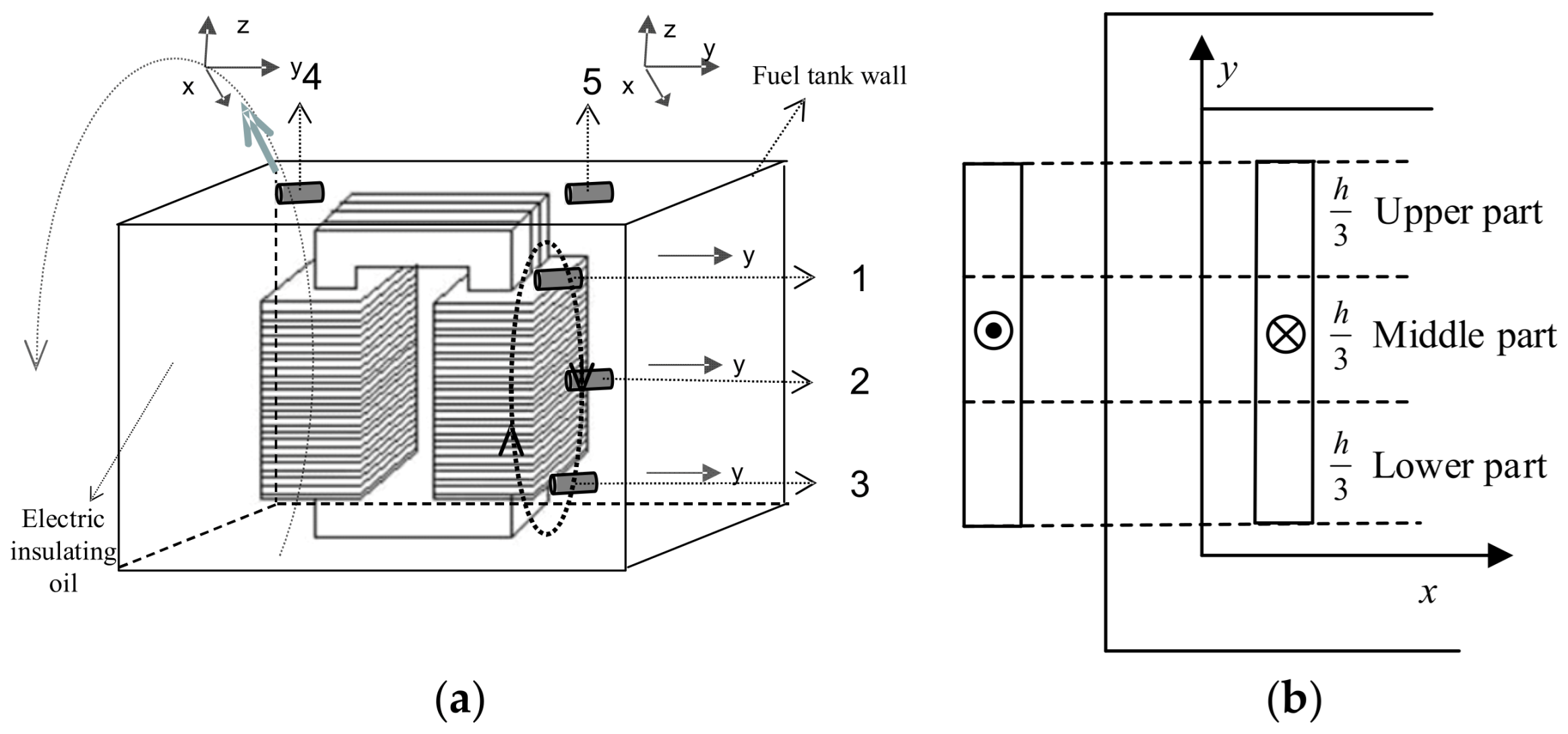
One type is the invasive installation method, where the optical leakage magnetic field sensor is installed on the surface of the windings inside the oil tank, as shown at points 1, 2, and 3 in Figure 2a. The other type is the non-invasive installation, where the optical leakage magnetic field sensor is installed on the surface of the external iron shell of the oil tank, as shown at points 4 and 5 in Figure 2a.
Since the optical fiber leakage magnetic field sensor is installed on the surface of the winding, it can sense a large leakage magnetic field magnetic induction intensity, thus having high sensitivity. As the leakage magnetic field is a spatial vector, the leakage magnetic field is symmetrical during the normal operation of the transformer, and the height of the winding is much greater than its width. The leakage magnetic field induction intensity is the highest at the air gap of the high- and low-voltage windings, and the magnetic force lines are parallel to the core, mainly being an axial magnetic field. When there is a slight inter-turn short circuit or arc-type fault in the winding, a radial magnetic field will occur. Therefore, the optical fiber leakage magnetic field sensor is installed at three measurement points on the surface, middle, and bottom of the winding to measure the radial magnetic field (y direction) of the winding, as shown in Figure 2a with 1, 2, and 3 measurement points. The three measurement points divide the winding into three regions: top, middle, and bottom. When faults occur in each region, the y-direction magnetic induction intensity sensed by the corresponding optical fiber sensor will change significantly, thereby accurately locating the fault point, as shown in Figure 2b.
For transformers with higher voltage levels, such as ±800 kV converter transformers, the optical fiber leakage magnetic field sensor may rupture in a high-voltage environment, and it may also be immersed in insulating oil for a long time. The insulating oil may enter the sensor’s glass shell. Therefore, a non-invasive installation method is adopted. The rated load current of the ±800 kV converter transformer may reach above 1 kA. Without a shielding layer installed at the top or bottom, or at certain determined positions, some leakage fluxes may pass through the top oil tank wall and penetrate into the air [25]. Therefore, by monitoring the changes in the spatial magnetic induction intensity vector at specific positions on the outer wall of the oil tank, early faults inside the windings can be detected, such as the 4 and 5 measurement points in Figure 2a.

2.3. Analysis of Transformer Leakage Flux and Principles of Differential Protection

2.3.1. Analytical Calculation of Leakage Magnetic Field Caused by Inter-Turn Short Circuit

The leakage magnetic field in the winding space exists in air or a linear medium such as transformer oil, and there is no magnetic saturation phenomenon. Therefore, the superposition theorem can be used for decomposition and calculation. The superposition principle of current density decomposition during inter-turn short circuit faults is shown in Figure 3. Among them, the blue part represents the operating windings, while the red part represents the windings that have experienced inter-turn short circuit faults.
To calculate the magnetic induction intensity of the transformer winding inter-turn short circuit fault within the calculation area, it can be decomposed into the normal winding magnetic induction intensity and the magnetic induction intensity generated by the current density excitation of the fault component. For the superposition diagram shown in Figure 3a, assuming that the winding with “label 5–6” has an inter-turn short circuit fault, the total magnetic induction intensity within the area is obtained by superimposing the magnetic induction intensity generated by the normal winding (normal current density component) and the magnetic induction intensity generated by the fault component of the “label 5–6” short-circuited winding (fault current density component).
The analytical expression for the radial magnetic induction intensity after any inter-turn fault in the winding within the region is shown in Formula (1), where represents the decomposition quantity of the normal winding current density, and represents the decomposition quantity of the current density of the inter-turn short-circuit fault winding. Taking the short-circuit of the “label 5–6” winding shown in Figure 3 as an example, the current density of the “label 5–6” winding during the inter-turn short-circuit is decomposed into J jk _ d and then substituted into Formula (1) to obtain the magnetic induction intensity after the inter-turn short-circuit.
B x x , y = j = 1 k = 1 J jk + J jk _ d k π μ 0 m j 2 + n k 2 h cos j π w x sin k π h y
In the formula, the analytical calculation of J jk _ d only includes the current density component of the inter-turn short-circuit fault, which is determined by the spatial coordinates of the calculation point.

2.3.2. Analysis of the Differential Principle of Fiber Leakage Magnetic Field Spike Variation

  • Leakage magnetic field distribution of interphase short circuit faults;
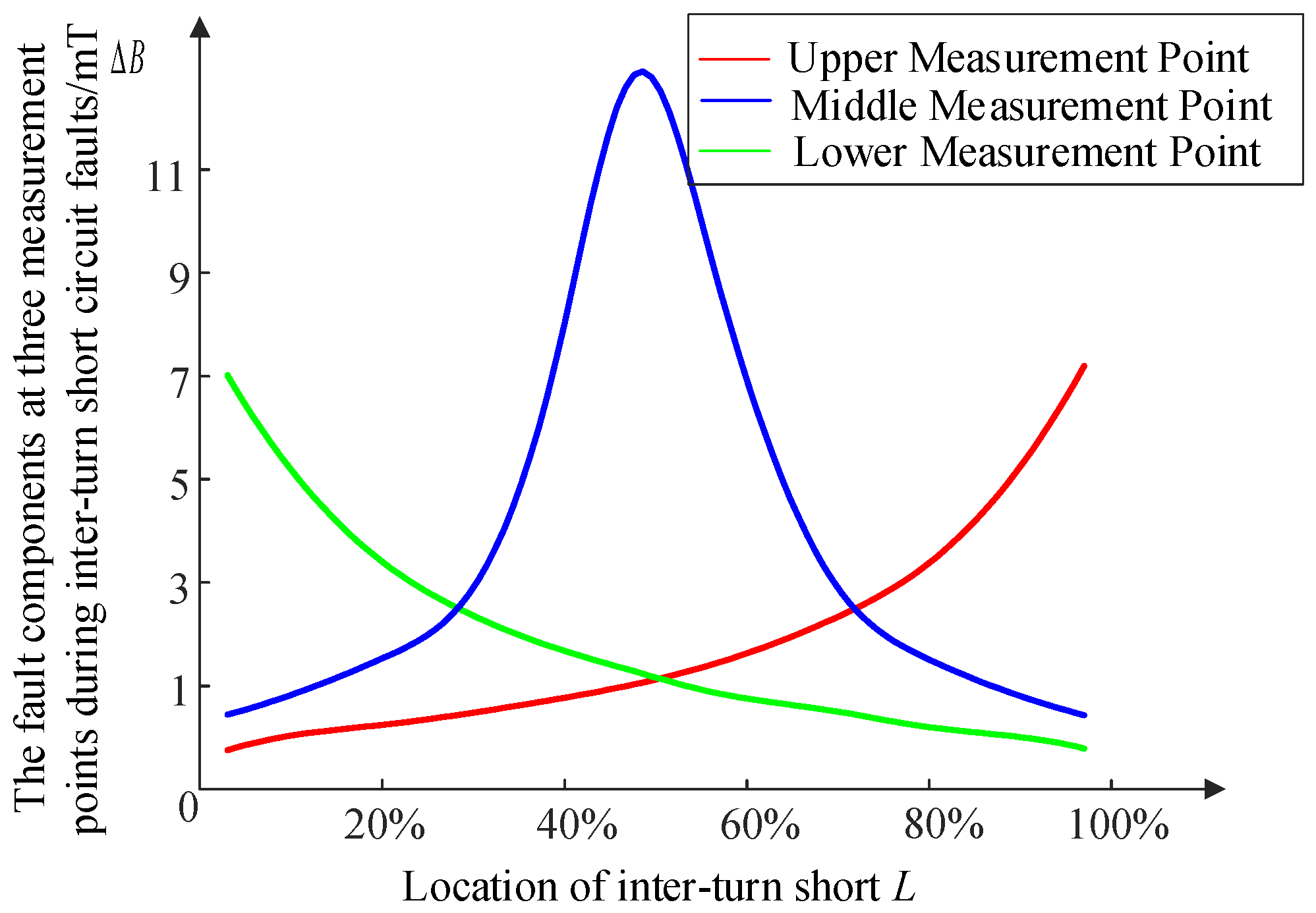
When a short-circuit fault occurs between turns of the transformer winding, the large short-circuit current flowing through the short-circuited turns will cause significant changes in the distribution of the space leakage magnetic field of the winding. When a 1-turn short circuit fault occurs at different axial positions of the winding, the variation patterns of the fault components of the leakage magnetic field at the three measurement points are shown in Figure 4.
As shown in Figure 4, the magnitudes of the fault components at the three measurement points are strongly correlated with the axial position where the fault occurs. When a 1-turn inter-turn short circuit fault occurs in the middle of the winding, the leakage magnetic induction intensity at the middle measurement point changes most significantly, and it satisfies the relationship that the fault component at the middle measurement point is greater than the sum of the fault components at the other two measurement points. When a one-turn inter-turn short circuit fault occurs in the lower part, the fault component at the lower end measurement point is the largest, and the fault component at the middle measurement point is greater than that at the upper end measurement point. When a one-turn inter-turn short circuit fault occurs in the upper part, the fault component at the upper end measurement point is the largest, and the fault component at the middle measurement point is greater than that at the lower end measurement point.
  • Leakage magnetic field differential criterion;
Based on the above fault characteristics, the two-week difference in the spatial leakage magnetic field vector before and after the sudden change in the spatial leakage magnetic field is used as the criterion for initiating the judgment. The logic is as follows:
Δ B up > B set 1 Δ B mid > B set 3 Δ B down > B set 2
At the instant when a short circuit fault occurs between the turns of the transformer winding, the end differential current increases rapidly. The formula is as follows:
Δ B ud = B up + B down > B set
The determination of whether the transformer has malfunctioned is based on the changes in the magnetic induction intensity ratios at the ① and ③ measurement points and the ② and ③ measurement points. The formula is as shown in (4):
B mid > k set 1 B up B mid > k set 2 B down
In the formula, Δ B up , Δ B mid and Δ B down represent the fault sudden variations in the radial magnetic induction intensity at the upper, middle, and lower ends of the winding; Δ B ud is the end differential quantity; B up , B mid and B down represent the fault quantities of the radial magnetic induction intensity at the upper, middle, and lower ends of the faulty winding.

2.3.3. Analysis of the Phase Difference Method for Measuring the Leakage Magnetic Field of Optical Fibers

  • Phase analysis of leakage magnetic field in inter-turn short circuit;
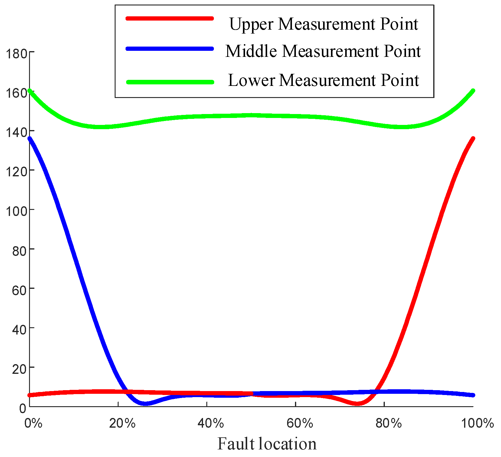
The magnetizing inrush current during normal operation of the transformer and during no-load closing, as well as the transitory current during external faults, does not alter the symmetry of the leakage magnetic field distribution. The phase difference in the leakage magnetic field at the symmetrical measurement points remains close to 180°. When a phase-to-phase short circuit fault occurs in the transformer, the phase of the leakage magnetic field shifts significantly. The phase relationships of the measurement points at different positions of the winding, namely the upper, middle, and lower positions, are shown in Figure 5.
As can be seen from Figure 5, when a 0.498% inter-turn short circuit fault occurs at the lower end of the transformer winding, the radial leakage magnetic phase variation at the lower measurement point is significantly greater than that at the upper measurement point. The closer the fault location is to the first 20% of the end, the more significant this difference becomes. Therefore, when the criterion for a slight inter-turn short circuit fault at the end is met, if the phase variation at the lower measurement point is greater than that at the upper measurement point, the fault location is within 20% of the lower end of the winding; if the phase variation at the lower measurement point is less than that at the upper measurement point, the fault location is within 20% of the upper end of the winding.
  • Leakage magnetic field phase difference protection criterion;
After a turn-to-turn short circuit fault occurs in the transformer winding, the phase of the end leakage flux changes significantly, and thus the phase difference momentum Δ B ud between the upper and lower measurement points changes significantly compared to normal operation. The protection criterion is shown in Formula (5).
Δ B ud = ( B up B down ) δ TD 1 > θ set 1
When a minor inter-turn short circuit fault occurs in the middle part of the transformer, the leakage magnetic field phase at the middle part undergoes significant changes. The phase difference momentum Δ B um between the upper part and the middle measurement point changes very noticeably. The protection criterion is as shown in Formula (6).
Δ B um = B up B mid δ TD 2 > θ set 2
When the transformer is operating under normal conditions, based on the installation positions of the measuring points, the phase difference between the upper and lower measuring points and the upper-middle measuring point fluctuates slightly around a fixed value. This fixed value is recorded as the phase difference standard value. When the transformer is operating under normal conditions, based on the installation positions of the measurement points, the phase difference between the upper and lower measurement points and the upper-middle measurement point fluctuates slightly around a certain value. This value is recorded as the phase difference standard value. In the above formula, δ TD 1 represents the standard deviation of the upper and lower measurement points, δ T D 2 represents the standard deviation of the upper-middle measurement point. B up , B mid , and B down are the initial phase angles of the leakage magnetic fields of the upper, middle, and lower measurement points, respectively. Through Formulas (5) and (6), minor inter-turn faults in the winding can be identified.

3. The Implementation Scheme of Optical Fiber Leakage Magnetic Field Balance Protection

The implementation scheme of the optical fiber leakage magnetic field balance protection device is shown in Figure 6. The core component of the fiber-optic leakage magnetic field sensor is a magneto-optical crystal, specifically yttrium iron garnet (YIG). The YIG crystal optical device and circuit are hermetically encapsulated within a glass tube and connected via glass fiber optic pigtails to form the fiber-optic sensor. Since this sensor contains no metallic materials, it can be safely deployed in high-voltage environments. To validate its high-temperature resistance, we conducted an 80 h immersion test in transformer oil at 110 °C. The results demonstrated that the magnetic-optical probe remained structurally intact, maintained normal light intensity measurements, and showed no signs of optical adhesive dissolution. These findings confirm the sensor’s excellent thermal and pressure resistance characteristics.
The optical fiber leakage magnetic field sensor adopts the Faraday magneto-optic principle and uses ordinary optical fibers. The accuracy reaches 0.01 mT, with low cost and facilitating the collection of leakage magnetic fields at multiple points of the winding. Inside the device, a laser power supply is placed to generate polarized light, which enters the optical fiber leakage magnetic field sensor through the optical fiber. Due to the effect of the spatial magnetic field, the polarization plane angle rotates, and the change in the polarization angle is converted into an electrical signal. This signal is converted into a digital signal through A/D conversion. Finally, the MPU board processes the signal to complete the function of optical fiber leakage magnetic field balance protection. The device has a serial communication port for device development and maintenance and also has an Ethernet port to achieve the comprehensive automation function of data transmission in the substation.
The MPU processing board has multi-task processing capabilities. For protection tasks, it is divided into two types: slow 1 s protection tasks and fast 2 ms protection tasks. For minor inter-turn faults and arc faults, the device has steady-state magnetic differential protection, sudden change magnetic differential protection, magnetic phase difference differential protection, and inter-turn fault location functions. For winding deformation, the device has steady-state magnetic field winding deformation detection and winding leakage magnetic field phase angle deformation detection. At the same time, the device also has a redundant measurement break monitoring function for optical fiber channels.

4. Testing of the Early Fault Proactive Defense System

4.1. Dynamic Model Test

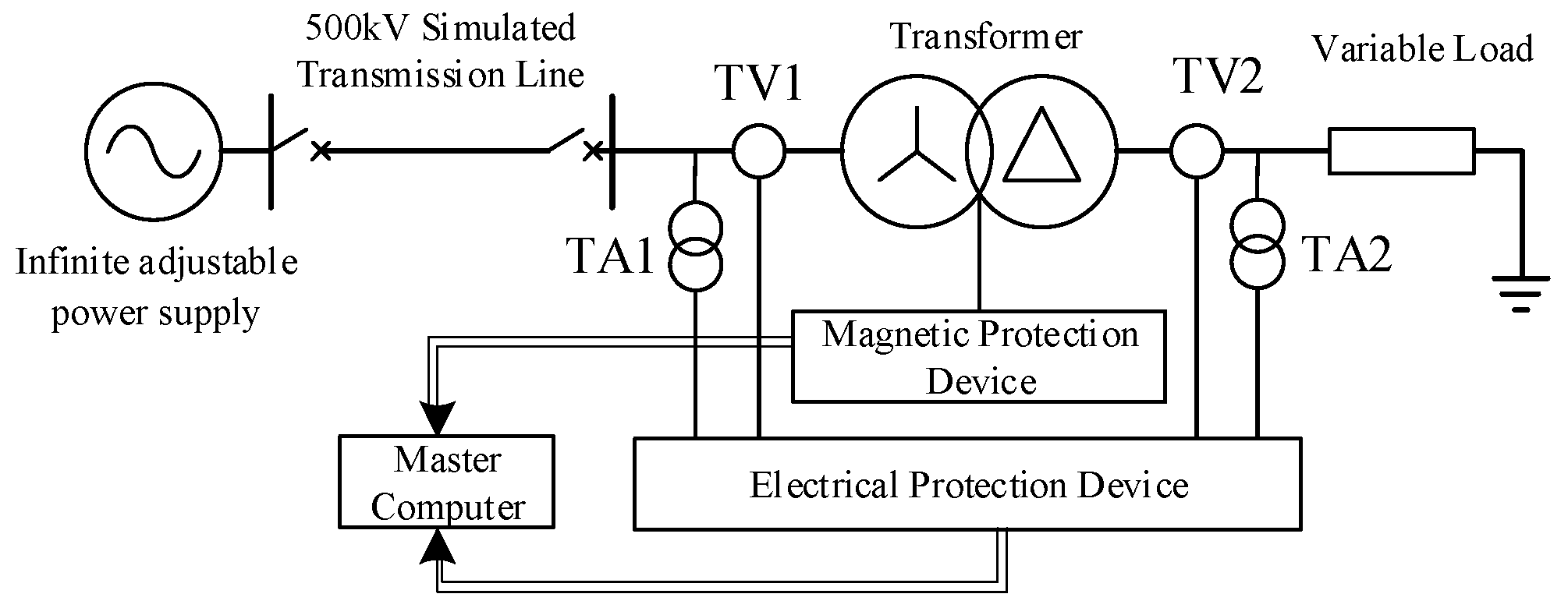
The wiring diagram of the die-casting test system is shown in Figure 7. The adjustable voltage range of the infinite power supply is 0 ~ 1.5   kV , the line parameters are x 1 = 0.1747   Ω / km , c 1 = 0.0336   μ F / km , and the length is L = 200   km . The test transformer is a three-phase double-winding transformer with Yn / d 11 connection, with a rated capacity of 50 kVA and a rated voltage of U 1 / U 2 = 1 / 0.4   kV . The winding parameters converted to the high-voltage side are R A = 0.5899   Ω , R B = 0.5896   Ω , R C = 0.5903   Ω , X A = X B = X C = 1.52   Ω , and the adjustable range of the load is 3.2 ~ 230.9   Ω . The current and voltage of the transformer are recorded by the fault recorder.
The dynamic model transformer is shown in Figure 8a. It can simulate minor inter-turn short-circuit faults and winding-to-ground discharge faults. The transformer control cabinet is depicted in Figure 8d, which can control the switching on and off of simulated inter-turn short circuits. Figure 8b shows the adjustable resistive load, used to simulate transformer faults under different load conditions. Figure 8c is the upper computer, used to view fault actions and fault recording data. The magnetic protection device is located in the upper right corner of Figure 8e. The overall layout of the experimental platform is illustrated in Figure 8e.

4.1.1. Transformer No−Load Closing

The leakage magnetic waveforms and phase difference protection verification waveforms under the no−load closing condition of the transformer are shown in Figure 9.
The leakage flux phase difference and leakage flux amplitude difference between the upper and lower measurement points during the transformer’s no−load closing operation are significantly lower than the set values. The leakage flux amplitude difference also falls below the set value. Therefore, the leakage phase difference protection scheme and the leakage flux amplitude difference protection scheme proposed in this paper are not affected by the excitation surge current.

4.1.2. Turn-to-Turn Fault

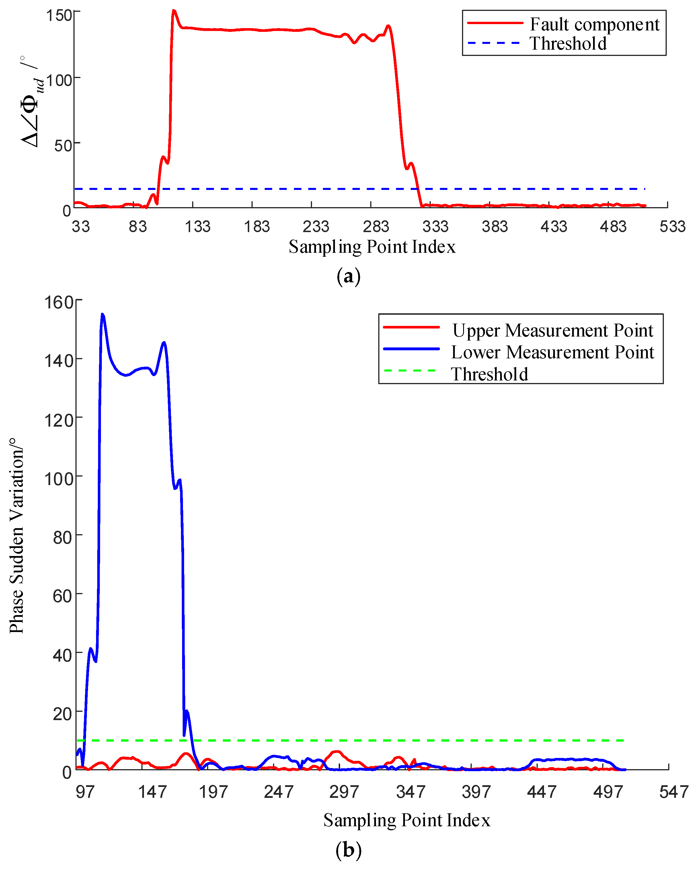
When a 0.995% inter-turn short circuit fault occurs at the lower end of the high-voltage winding of the transformer, the verification curve of the leakage magnetic phase difference protection is shown in Figure 10.
When a 0.995% inter-turn short circuit fault occurs at the lower end of the high-voltage winding of the transformer, the verification curve of the leakage magnetic phase difference protection is shown in Figure 10. After identifying that a winding inter-turn short circuit fault has occurred in the transformer, the logic for locating and identifying the inter-turn short circuit fault is entered. The phase difference variation at the upper measurement point is always less than the threshold value, while the phase difference variation at the lower measurement point is much greater than that of the upper measurement point. This meets the condition for identifying an inter-turn short circuit fault at the lower end of the winding. The inter-turn short circuit fault occurred at the lower end face of the winding up to 20% of its height above.
When a 0.995% (2 turns) inter-turn short circuit fault occurs in the upper part area, the leakage magnetic field fault component at the intermediate measurement point is significantly greater than that at the upper end measurement point, as shown in Figure 11. The measurement data simultaneously meet the start-up condition and the inter-turn short circuit fault identification condition. It is possible to successfully identify the inter-turn short circuit fault within 10 ms (half a cycle) with 16 sampling points.

4.1.3. Winding Discharge to Ground

It consists of an arc generation device and a discharge voltage measurement device. The moment when the arc discharge channel is established is shown in Figure 12.
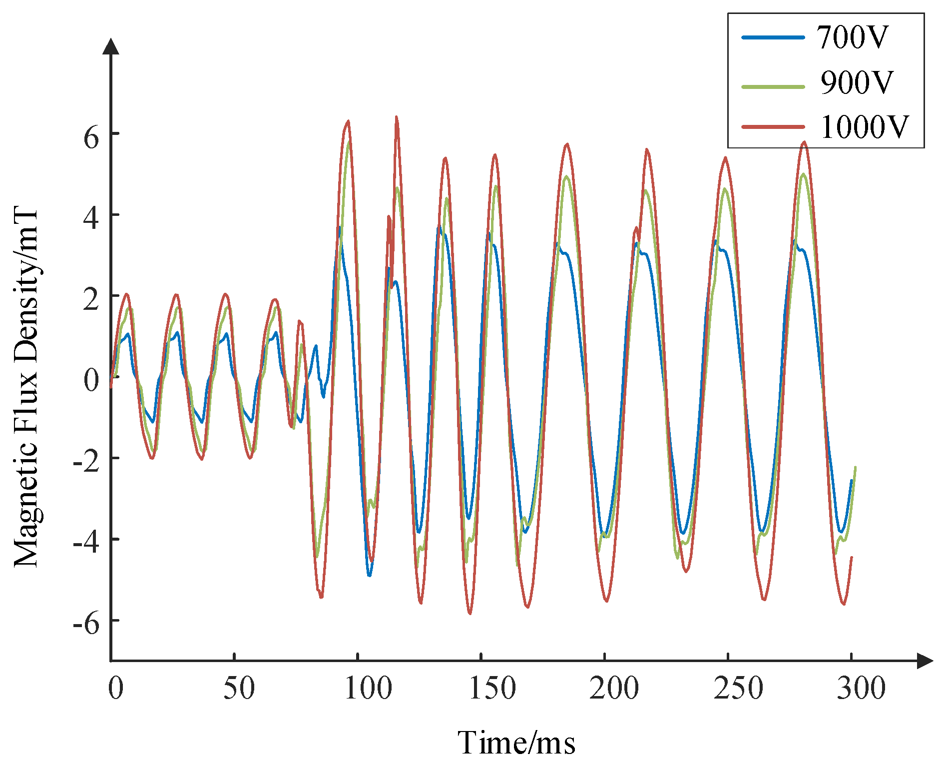
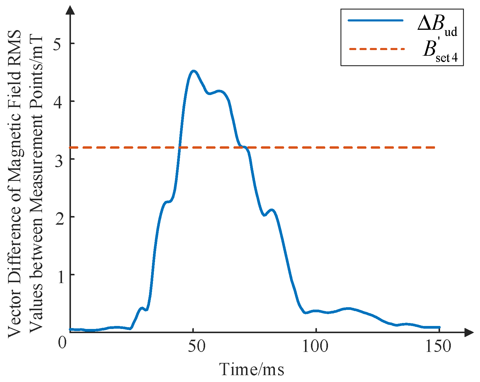
When a fault of ground discharge occurs in the winding, the differential quantity data of the magnetic field at the ends formed by the upper and lower measurement points are shown in Figure 13.
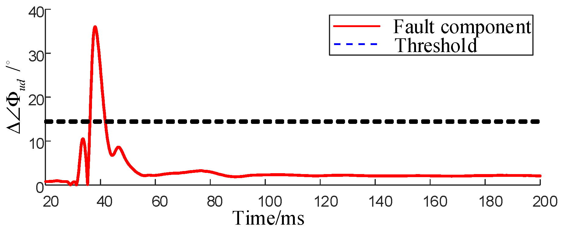
As can be seen from Figure 14, when a fault of ground discharge occurs in the transformer winding, the magnetic induction intensity of the leakage magnetic field of the faulty phase undergoes a drastic change and meets the protection criterion. As shown in Figure 15, the leakage phase difference current protection criterion is satisfied, and the protection can operate correctly.

4.1.4. Summary of the Dynamic Model Test

Taking the A-phase winding as an example, tests were conducted for various degrees of inter-turn short circuits and no-load closing operations. Table 1 lists the relevant parameters and corresponding measures after the occurrence of the fault.

4.2. Field Engineering Application of the Early Fault Active Defense System

The early fault diagnosis system for transformers with latent faults has been applied in the dry-type station transformers of a certain hydropower station, as shown in Figure 16b. The latent fault diagnosis system for the dry-type station transformer in a certain hydropower station includes an optical leakage magnetic field measurement system a magnetic differential protection device; an early fault diagnosis device based on the waveform difference in the digital twin analytical model; and online diagnosis system software for latent faults of the dry-type transformer with multi-physical quantity feature coupling.

5. Conclusions

This study investigates transformer leakage magnetic fields as characteristic quantities, analyzing their distribution patterns under both normal and fault conditions to establish corresponding protection criteria. Building upon this foundation, we examined sensor installation methodologies and developed both intrusive and non-intrusive installation approaches. Subsequently, we designed and implemented an optical fiber-based leakage magnetic field active defense system for early transformer fault detection, yielding the following key findings:
(1)
Using leakage magnetic fields as fault indicators, we proposed and validated both amplitude-differential and phase-differential protection principles, establishing comprehensive protection criteria.
(2)
Through comparative analysis of two sensor installation methods, we successfully developed an active defense system for early transformer fault detection based on fiber-optic leakage magnetic field monitoring.
(3)
Experimental verification using a purpose-built early fault simulation platform demonstrated the system’s effectiveness in accurately identifying incipient transformer faults while maintaining immunity to false operations during no-load switching operations.
(4)
The developed fiber-optic leakage magnetic field active protection system has been successfully deployed at the Wudongde Hydropower Plant, achieving highly efficient monitoring and protection against early-stage transformer faults.

Author Contributions

Conceptualization, J.W. and Y.L.; methodology, X.D.; software, X.D. and Z.T.; validation, J.M., Y.L. and S.L.; formal analysis, J.W.; investigation, W.T.; data curation, Z.T.; writing—original draft preparation, J.W. and Y.L.; writing—review and editing, J.W., Y.L. and S.L.; visualization, W.T.; All authors have read and agreed to the published version of the manuscript.

Funding

This research was funded by China Yangtze Power Co., Ltd., project number 5223020052, grant number Z522302029. Here, we would like to express our gratitude for the strong support from China Yangtze Power Co., Ltd.

Data Availability Statement

The data included in this article that support the results of this study can be obtained by contacting the corresponding author of this article.

Conflicts of Interest

The authors declare that this study received funding from China Yangtze Power Co., Ltd. The funder had the following involvement with the study: paper writing, data collection, and analysis.

References

  1. Jia, Y.; Ji, S.; Li, J.; Jia, S.; Luo, X.; Wang, K.; Sun, J. Overview on the Characteristics of Power Frequency Arc in Transformer Oil and Transformer Explosion Protection. Proc. CSEE 2024, 44, 2910–2927. [Google Scholar]
  2. Moradzadeh, A.; Pourhossein, K.; Mohammadi-Ivatloo, B.; Mohammadi, F. Locating Inter-Turn Faults in Transformer Windings Using Isometric Feature Mapping of Frequency Response Traces. IEEE Trans. Ind. Inform. 2021, 17, 6962–6970. [Google Scholar] [CrossRef]
  3. Ou, Q.; Luo, L.; Li, Y.; Yang, X.; Zhou, L. An Evaluation Method for Short-Circuit Cumulative Mechanical Damage of Power Transformer. Trans. China Electrotech. Soc. 2024, 39, 2578–2590. [Google Scholar]
  4. Zhang, F.; Li, X.; Zhu, X.; Zhuang, Z.; Shi, Y. Assessment of the Withstand Ability to Short Circuit of Inner Windings in Power Transformers Considering the Degree of Thermal Aging. Proc. CSEE 2022, 42, 3836–3846. [Google Scholar]
  5. Du, J.; Fan, Z.; Fan, Z.; Wang, Q.; Li, P. Research on Abnormal Data Identification and Content Prediction of Dissolved Gas in Power Transformer Oil. Power Syst. Technol. 2025, 49, 844–853. [Google Scholar]
  6. Wen, Y. Research on On-line Monitoring Device of Transformer Winding Deformation by Frequency Response Method. Master’s Thesis, North China Electric Power University, Beijing, China, 2024. [Google Scholar]
  7. Deng, X.; Zhang, Z.; Xia, Y.; Wang, L.; Wu, C.; Fan, J.; Wang, F. Vibration signal characteristic analysis of power transformer winding under deformation state. Adv. Technol. Electr. Eng. Energy 2024, 43, 13–23. [Google Scholar]
  8. Zhang, F.; Ji, S.; Shi, Y.; Lu, W.; Li, D.; Chen, L. Research on Transformer Winding Vibration and Propagation Characteristics. Proc. CSEE 2018, 38, 2790–2798, 2849. [Google Scholar]
  9. Xia, Y.; Li, M.; Xiang, T.; Qin, S.; Deng, Q.; Wang, X. Fault diagnosis of transformer winding and core based on SOM. J. Eiectric Power Sci. Technol. 2018, 33, 129–134. [Google Scholar]
  10. Ouyang, X.; Chen, M.H.; Zhou, Q.; Chen, W.G.; Zhang, Z.X.; Luo, Z.H. A Novel All-dielectric Optical Fiber Temperature-magnetic Field Dual-parameter Sensor. Proc. CSEE 2023, 43, 8114–8124. [Google Scholar]
  11. Li, D.; Liu, Y.; Fan, X.; Li, H.; Li, Y. Discrimination and Degree Detection of Axial and Radial Deformation in Transformer Windings Based on Distributed Sensing of Ribbon Optical Fibers. Proc. CSEE 2025, 45, 803–813. [Google Scholar]
  12. Liu, Y.; Li, H.; Gao, S.; Wang, J.; Fan, X. Research on Application of Distributed Optical Fiber Sensing in Monitoring of Temperature and Winding Deformation of Large Transformer. Proc. CSEE 2022, 42, 6126–6135, 6186. [Google Scholar]
  13. Deng, X.; Zhu, H.; Yan, K. Magnetic Balance Protection of Transformers Based on Optical Fiber Leakage Magnetic Field Measurement. Trans. China Electrotech. Soc. 2024, 39, 628–642. [Google Scholar]
  14. Zhou, Y.; Wang, X. The on-line monitoring method of transformer winding deformation based on magnetic field measurement. Electr. Meas. Instrum. 2017, 54, 58–63, 87. [Google Scholar]
  15. Wang, L. Research on a New Non Electric Quantity Protection Strategy of Oil Immersed Transformers. Master’s Thesis, Zhejiang University, Hangzhou, China, 2020. [Google Scholar]
  16. Haghjoo, F.; Mostafaei, M.; Mohammadi, H. A New Leakage Flux-Based Technique for Turn-to-Turn Fault Protection and Faulty Region Identification in Transformers. IEEE Trans. Power Deliv. 2018, 33, 671–679. [Google Scholar] [CrossRef]
  17. Zheng, Y.; Gong, X.; Pan, S.; Sun, J.; Deng, J. Analysis on Leakage Flux Characteristics of Turn-to-Turn Short-circuit Fault for Power Transformer. Autom. Electr. Power Syst. 2022, 46, 121–127. [Google Scholar]
  18. Xian, R.; Zhang, B.; Liu, X.; Jiang, X.; Chen, L. Application of finite element analysis to transient characteristics of interturn short circuit in power transformer windings. Electr. Mach. Control. 2021, 25, 130–138. [Google Scholar]
  19. Deng, X.; Zhang, Z.; Zhu, H.; Yan, K. Early fault diagnosis of transformer winding based on leakage magnetic field and DSAN learning method. Front. Energy Res. 2023, 10, 1058378. [Google Scholar] [CrossRef]
  20. Deng, X.; Zhu, H.; Yang, M.; Wu, W.; Liu, S. Research on Early Fault Protection Method of Transformer Winding Based on Multi-state Model. Proc. CSEE 2022, 42, 6704–6715. [Google Scholar]
  21. Liu, J.; Li, Z.; Zhou, Y. Transformer windings based on leakage field and ICOA-ResNet early fault diagnosis. Power Syst. Prot. Control. 2024, 52, 99–110. [Google Scholar]
  22. Deng, X.; Yan, K.; Zhu, H.; Zhu, H.; Zhang, Z. Transformer winding early fault protection based on circuit-magnetic leakage field multi-state analytical model. Power Syst. Technol. 2023, 47, 3808–3821. [Google Scholar]
  23. Ji, M.; Qi, B.; Zheng, W.; Huang, M.; Li, C.R.; Wang, J. Coding Diagnosis Method Based on Leakage Distribution Law UnderTypical Winding Defects of Transformers. Power Syst. Technol. 2024, 48, 2133–2142. [Google Scholar]
  24. Jia, Y.; Jia, S.; Luo, X.; Ji, S.; Li, S. Research on comparison on rapid detection methods of transformer internal arc fault. High Volt. Eng. 2024, 50, 2158–2165. [Google Scholar]
  25. Wu, S.; Ji, S.; Sun, J.; Liang, N.; Zhao, T.; Dai, S. Vibration Monitoring and Variation Law of Converter Transformer in Operation. High Volt. Eng. 2022, 48, 1561–1570. [Google Scholar]
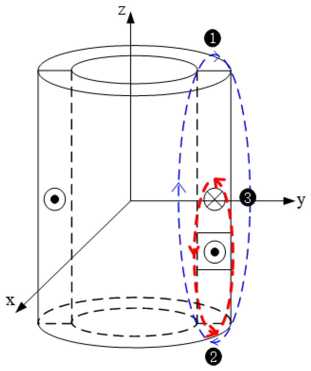
Figure 1. Distribution diagram of magnetic field lines of winding leakage field.
Energies 18 04497 g001
Figure 2. Magnetic balance protection optical fiber sensor installation method: (a) the installation method of optical fiber sensors; (b) winding fault location and zoning.
Energies 18 04497 g002
Figure 3. Current density superposition schematic diagram: (a) total current density; (b) normal current density; (c) fault current density.
Energies 18 04497 g003
Figure 4. The fault component amplitude changes with different height turns.
Energies 18 04497 g004
Figure 5. Radial magnetic leakage phase changes at different positions.
Energies 18 04497 g005
Figure 6. Principle of magnetic flux leakage balance protection of optical fiber.
Energies 18 04497 g006
Figure 7. Dynamic model experiment system wiring.
Energies 18 04497 g007
Figure 8. Physical drawing of dynamic model system: (a) transformer; (b) adjustable resistive load; (c) upper computer; (d) transformer control cabinet; (e) overall wiring of the mold testing system.
Energies 18 04497 g008
Figure 9. No−load closing MFL waveform and phase difference dynamic protection check: (a) no−load closing inrush leakage flux waveform; (b) phase difference variation between upper and lower measurement points; (c) leakage flux differential protection.
Energies 18 04497 g009
Figure 10. Lower end of winding 0.995% turns short fault phase difference dynamic protection check: (a) phase difference variation between upper and lower measurement points; (b) phase sudden variation between upper and lower measurement points.
Energies 18 04497 g010
Figure 11. Fault start-up curve between upper turns of winding.
Energies 18 04497 g011
Figure 12. Arc discharge physical picture.
Energies 18 04497 g012
Figure 13. Magnetic induction intensity of power failure under different voltages at the upper measuring point.
Energies 18 04497 g013
Figure 14. Rated voltage winding discharge fault field end difference momentum.
Energies 18 04497 g014
Figure 15. Winding to ground discharge fault phase difference dynamic protection check.
Energies 18 04497 g015
Figure 16. Application case of dry-type transformer in a hydropower station: (a) device connection; (b) equipment panel assembly.
Energies 18 04497 g016
Table 1. Dynamic model test content.
Differential Criterion Based on Sudden Change QuantityDifferential Criterion Based on Steady-State QuantityPhase Difference Criterion
Characteristic QuantityAction and PositioningCharacteristic QuantityAction and PositioningCharacteristic QuantityAction and Positioning
1.49% inter-turn short circuit in the lower part of the winding Δ B up / mT 0.267correct operation
lower part
B up / mT 1.352correct operation
lower part
Δ B ud / ° 151.475correct operation
lower part
Δ B um / ° 105.511
Δ B mid / mT 0.786 B mid / mT 0.774 Δ B up / ° 20.496
Δ B mid / ° 85.015
Δ B down / mT 1.478 B down / mT 0.933 Δ B down / ° 130.977
0.995% inter-turn short circuit in the middle of the winding Δ B up / mT 0.089correct operation
middle part
B up / mT 1.067correct operation
middle part
Δ B ud / ° 1.696correct operation
middle part
Δ B um / ° 170.609
Δ B mid / mT 0.531 B mid / mT 0.393 Δ B up / ° 15.085
Δ B mid / ° 155.524
Δ B down / mT 1.386 B down / mT 0.643 Δ B down / ° 16.781
no-load closing Δ B up / mT -non-operating B up / mT -non-operating Δ B ud / ° 2.974non-operating
Δ B mid / mT - B mid / mT - Δ B um / ° 50.735
Δ B down / mT - B down / mT -
Disclaimer/Publisher’s Note: The statements, opinions and data contained in all publications are solely those of the individual author(s) and contributor(s) and not of MDPI and/or the editor(s). MDPI and/or the editor(s) disclaim responsibility for any injury to people or property resulting from any ideas, methods, instructions or products referred to in the content.