1. Introduction
CO
2 capture, geological storage and utilization (CCUS) is internationally recognized as one of the most effective means of mitigating global warming [
1,
2,
3]. In general, CCUS is divided into three distinct components: CO
2 capture, utilization, and storage. CO
2 utilization is manifested mainly in CO
2-enhanced oil recovery (EOR) and CO
2-enhanced gas recovery (EGR) projects, photocatalytic conversion of CO
2 [
4], and biological CO
2 conversion. CO
2 storage mainly includes geologic CO
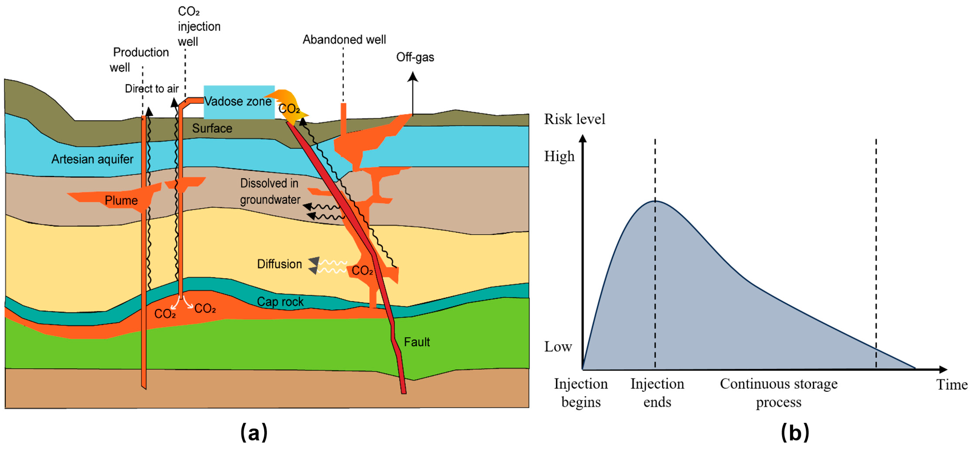
2 storage (GCS), mineralization, and marine storage, among which GCS is the most important storage method. During the process of geological storage, CO
2 may leak through several paths, such as abandoned wells, reactivated faults and caprocks [
5]. The leakage of CO
2 will pollute the groundwater and subsurface soil and also has a chance of being released into the atmosphere [
6,
7,
8]. Before implementing any CCUS project, conducting a CO
2 leakage risk assessment should be a top priority [
9].
Several CO
2 leakage risk assessment methods were proposed recently. The available methods can be divided into qualitative and quantitative assessment methods. Qualitative risk assessment methods primarily include the following frameworks: The Containment Assurance Scenario and Significance Identification Framework (CASSIF), developed by Ferhat Yavuz et al. [
10], which employs fault leakage analysis, wellbore integrity evaluation, and seal failure detection to identify critical events in geological containment systems. This framework optimizes utilization of the Features, Events, and Processes (FEP) database through real-time scenario matching, significantly enhancing the modeling accuracy of risk significance identification. The Structured What-If Technique (SWIFT) proves particularly effective for assessing risks in inaccessible hazardous environments where consequence pathways remain ambiguous. Through systematic generation of hypothetical failure scenarios, SWIFT enables preemptive risk evaluation of complex industrial operations [
11]. The Vulnerability Evaluation Framework (VEF) serves as a conceptual tool for systemic vulnerability assessment. This framework assists regulatory bodies and engineering professionals in establishing customized risk metrics while providing methodological guidance for design validation, risk quantification, and regulatory compliance management [
12]. Earlier CCUS leakage risk evaluations mostly used evaluation frameworks and qualitative methods due to a lack of specific data, which resulted in greater uncertainty and risk misclassification. They could not dynamically assess the real-time changes in leakage risk during the sequestration process, and had limitations in decision-making. Thus, this method is gradually being replaced by quantitative risk assessment methods [
11].
Quantitative risk assessment methods effectively make up for the shortcomings of qualitative assessment methods, mainly for the realization of quantitative portrayal of the risk of leakage, such as calculating the leakage volume or the risk of leakage from a single leakage path over a certain period of time [
13]. They can accurately provide input for relevant monitoring and protection measures [
14]. The main quantitative risk assessment methods include the overall assessment of CO
2 leakage risk with the Performance and Risk (P&R) [
15] and the main potential leakage path identification methods are the Certification Framework Approach (CFA) [
16], CO
2-Predicting Engineered Natural Systems (CO
2-PENS) [
17], and Risk Interference Subsurface CO
2 Storage (RISCS) [
18]. The main methods used recently for assessing the risk of CO
2 leakage in CCUS-EGR projects are described in the following section, but these various methods all have certain limitations. The experimental approach includes core replacement experiments, fracture expansion and permeability tests, etc. This method offers a visual representation of the reservoir’s response to CO
2 injection, but its limitations are also evident. It cannot reflect the complex geological conditions of the actual subsurface reservoir, nor can it portray the long-term evolution of the geological sealing process. The Probabilistic Risk Assessment Method (PRA) is a statistical-based approach that utilizes leakage probability statistics and Fault Tree Analysis (FTA) to quantitatively assess the risk of leakage. However, the method is inherently dependent on data, and the lack of disclosure of leakage data from the CCUS-EGR project restricts the reliability of the results due to governmental policy. Machine learning methods, as one of the key quantitative risk assessment approaches, can use neural networks and other artificial intelligence algorithms to analyze field monitoring data from actual projects and predict leakage risk in conjunction with existing historical processes. The primary benefit of this approach is the enhanced accuracy of the calculated leakage risk probability when combined with extensive data training calculations. However, the key disadvantage is the lack of interpretability, resulting in a black-box model that hinders the provision of reliable explanations for physical mechanisms [
19]. Due to the lack of sufficient evaluation data and the dynamic nature of leakage risk over time, the accuracy and timeliness of existing quantitative evaluation methods are limited.
Numerical simulation is a mature and widely used tool for data generation [
20]. It uses professional numerical simulation software, such as TOUGH (Lawrence Berkeley National Laboratory, Berkeley, CA, USA), CMG (Computer Modeling Group Ltd., Calgary, AB, Canada), ECLIPSE (Schlumberger Ltd., Houston, TX, USA), etc., to construct the corresponding numerical model and accurately predict the CO
2 migration distribution and leakage risk during the process of storage [
21]. The integration of risk assessment and numerical simulation holds significant potential in addressing the insufficient dynamic assessment capabilities inherent in existing quantitative evaluation methodologies.
In recent years, quantitative evaluation methods have gradually become the mainstream method of risk assessment. Aiming at the problem of wellbore leakage in the process of CO
2 geological storage in a saline aquifer, Gao et al. [
22] established a quantitative risk evaluation index system based on an analytic hierarchy process so as to determine the influence weight of each influencing factor on leakage according to the score. Sorgi et al. [
23] proposed a quantitative assessment method for leakage risk, which introduced measurement, monitoring and verification methods to avoid qualitative analysis or subjective judgment involved in risk assessment and analysis. Unfortunately, the method lacks actual site applicability verification. Using a quantitative analysis method, Dou et al. [
24] established a heat and mass transfer and distribution model of offshore gas production wells, explored the physical process of gas leakage and migration, quantitatively evaluated the influence of different factors, and designed a series of risk prevention measures. By comprehensively comparing qualitative, semi-quantitative and quantitative methods, the qualitative evaluation method has the advantages of simple operation and short completion time, but it has poor ability in later leakage quantification and risk assessment. The semi-quantitative method can achieve advantages in operability and flexibility; the advantage of the quantitative method is that it has sufficient data persuasiveness in terms of data accuracy and uncertainty processing. The disadvantage is that the operation is difficult and the completion time is long [
25]. The quantitative evaluation method established in this paper effectively solves the problem of difficult operation. Users can assign values in turn according to the scoring table and combine the existing numerical simulation results of site injection, which greatly reduces the working time.
Internationally, Enhanced Gas Recovery (EGR) technology remains at a low technological maturity level, with limited documented implementation cases [
26]. Notably, China achieved a milestone in 2024 by launching its first CCUS-EGR pilot demonstration project at the Wolonghe Gas Field. Characterized by advanced technical maturity and comprehensive supporting infrastructure, this pioneering project has successfully completed the first period of CO
2 injection.
Considering the limitations and shortcomings of the above risk assessment methods, this paper focused on identifying the leakage pathways, determining the values of various leakage indicators on the overall storage risk, and combining the results of numerical simulation to propose a leakage risk assessment method for long-term CCUS projects. The Maokou gas reservoir in the Wolonghe field, southwest China, was selected as an application case to investigate the dynamic assessment results of CO2 storage risk under different time scales, which will provide a scientific method for field injection storage in the subsequent study area and a reliable basis for developing a leakage risk monitoring program.
3. Results and Discussion
3.1. CO2 Dynamic Leakage Risk Assessment Framework
Aiming at the identified factors and sub-factors, the grading assignment method was used to determine the corresponding scores of different levels according to the influence of different indicators on the leakage risk. The specific scoring rules for different risk factors are shown in
Table 6.
3.2. Validation of the Numerical Model of the Wolonghe EGR Project
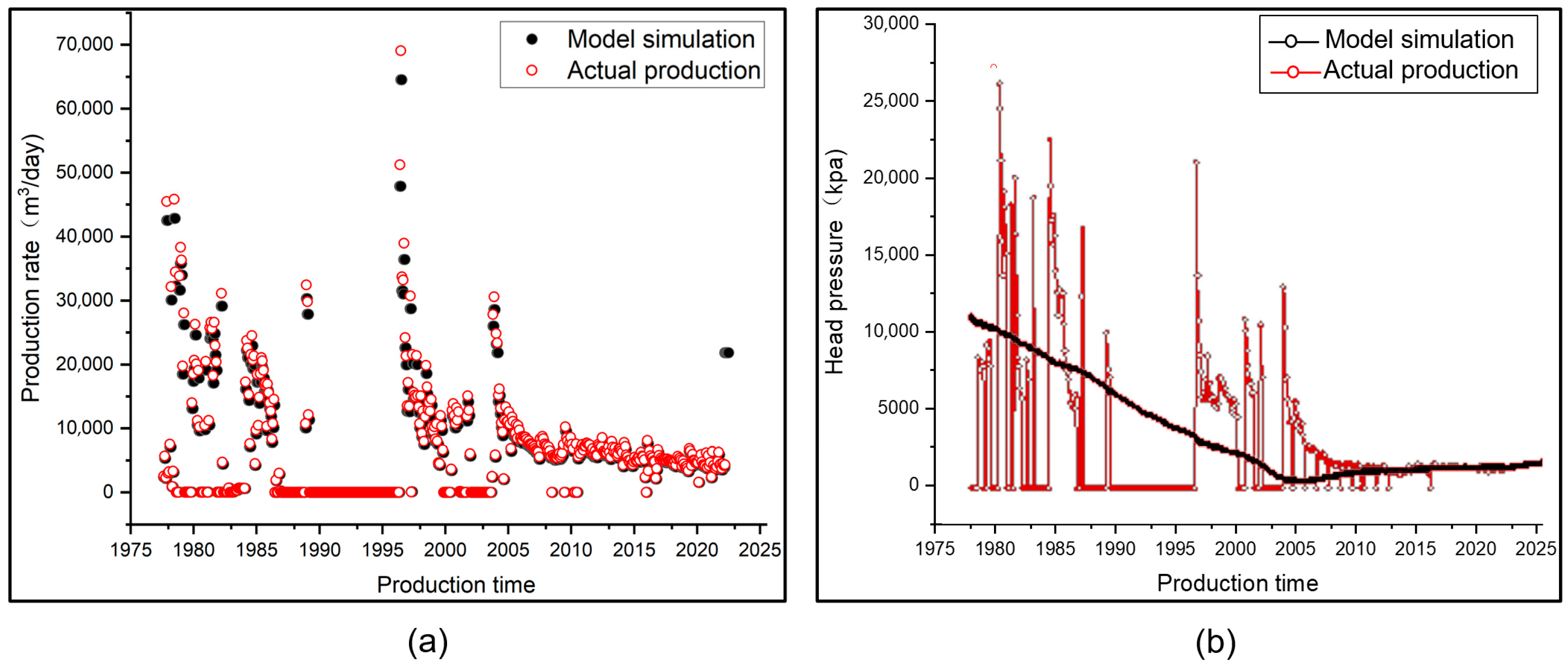
It is important to validate the established numerical model with historical production data to guarantee the accuracy and scientific validity of the simulation results. In this paper, the historical gas production rate of W47 and wellhead pressure were employed to calibrate the numerical model by model fitting, and the fitted results are shown in
Figure 5.
The fitting results on gas production rate show good agreement with the historical data, especially after 2005. In the early stages of production, due to the lack of historical data, there is a large error between the simulated and actual values of wellhead pressure. However, with the enrichment of production data samples after 2010, the fitting results of wellhead pressure have become increasingly realistic. Overall, it can be seen that the numerical model constructed in this paper demonstrates a good historical fitting effect. The model is accurate and reliable, and the simulation results obtained can be used as an important basis for subsequent risk assessment and the development of monitoring programs.
3.3. Simulation Results Under Normal Operating Conditions
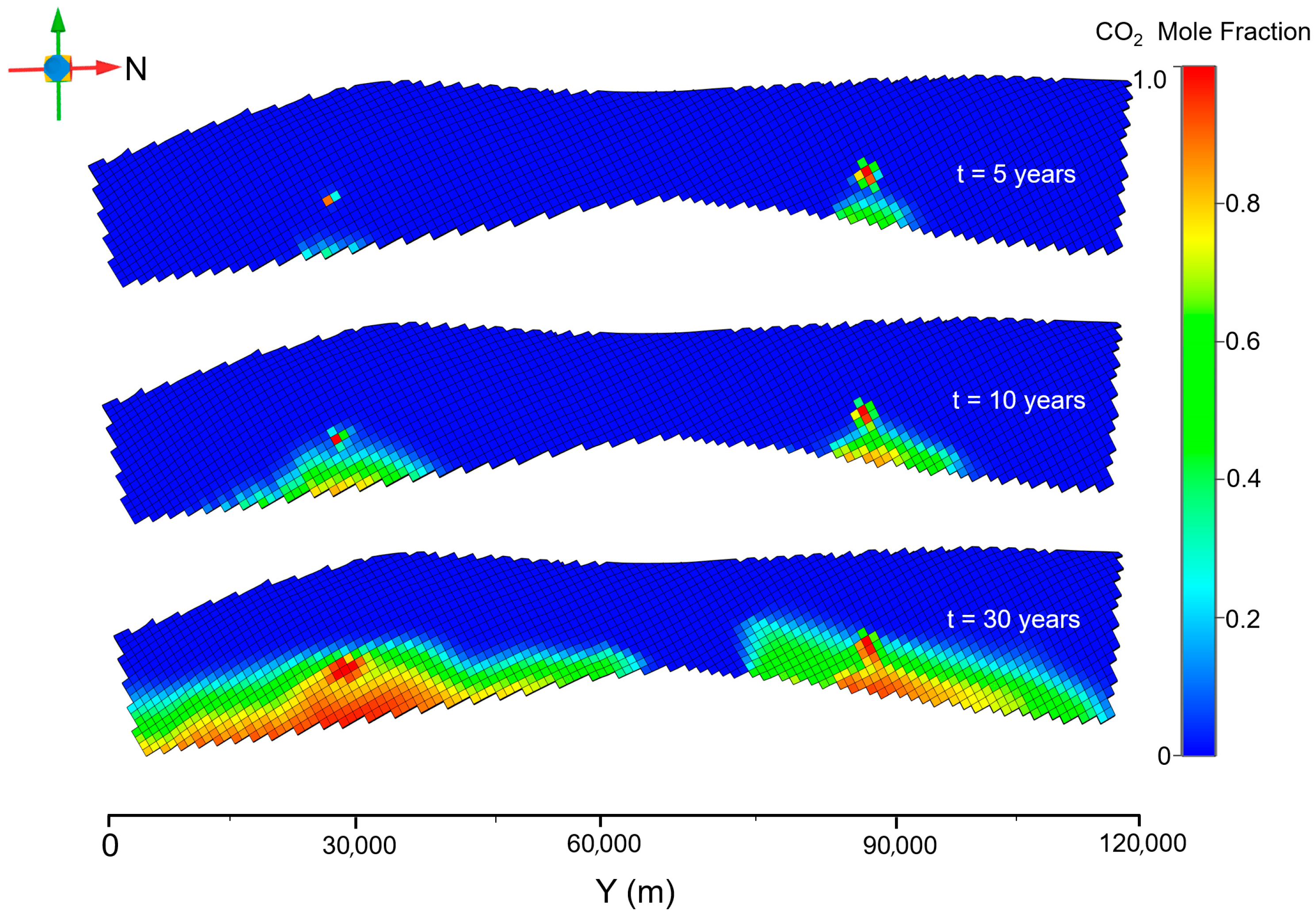
The simulation results of the CO
2 mole fraction distribution at the top of the reservoir for 5 years of gas injection, 10 years of gas injection, and 30 years of gas injection under normal operating conditions are shown in
Figure 6.
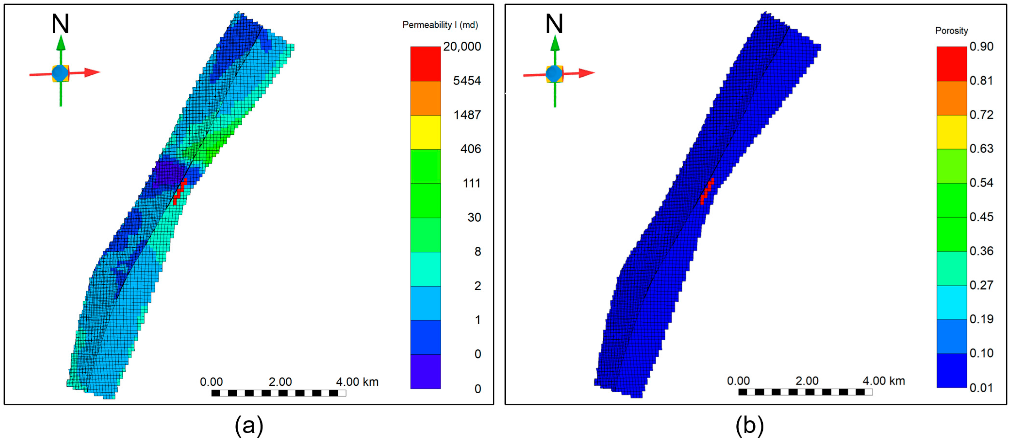
The permeability distribution of the reservoir exhibits a distinct pattern of higher values in the eastern region compared to the western region, consequently leading to preferential eastward migration of injected CO
2 (
Figure 6).
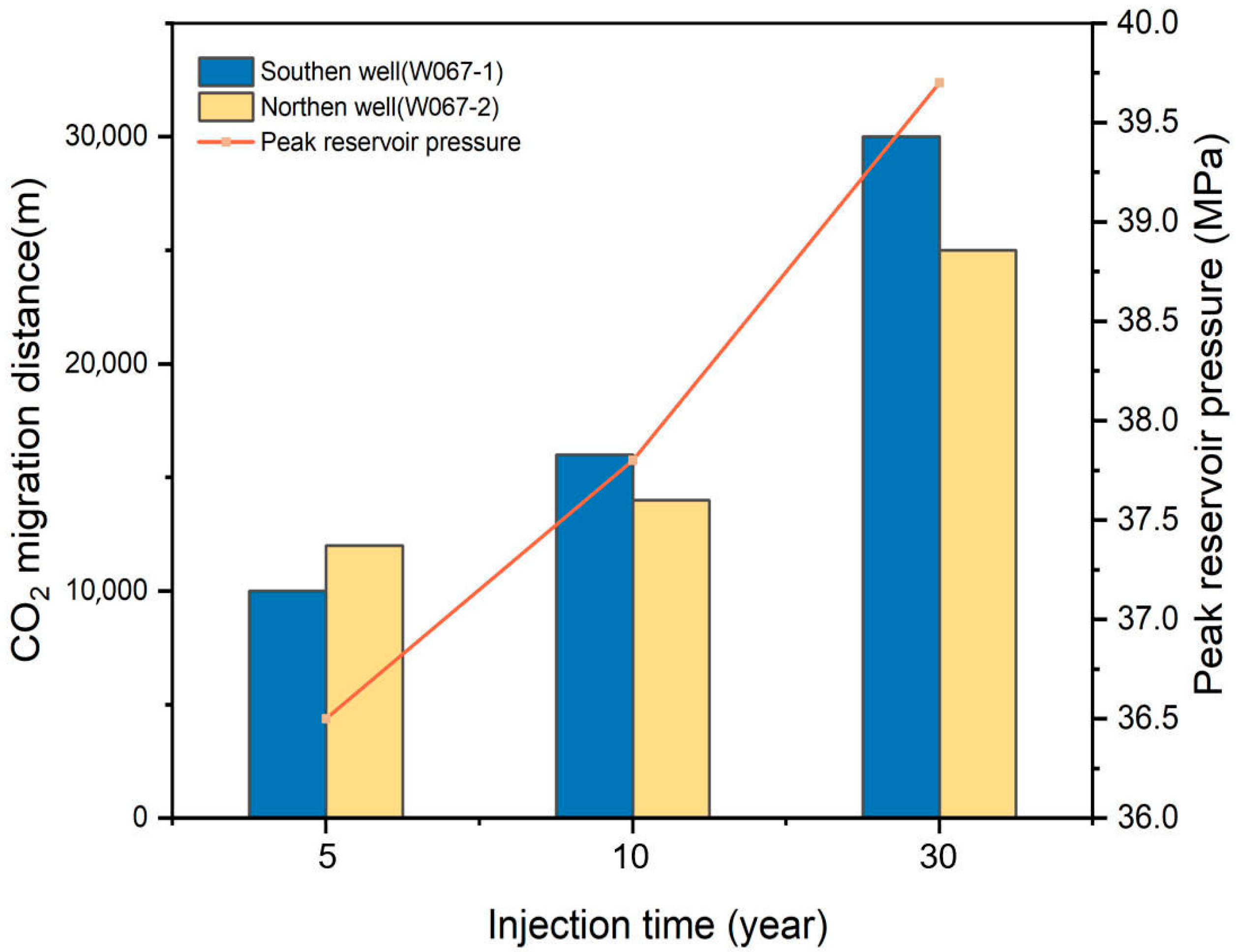
Figure 7 shows the CO
2 migration distance at different times of gas injection. For phase I (injection rate: 100,000 m
3/day, duration: 5 years), the analysis reveals that the maximum north–south migration distance of CO
2 from the southern injection well reaches approximately 10,000 m, while the northern injection well demonstrates a greater migration extent of 12,000 m along the same orientation. Additionally, a discernible migration plume extending approximately 8000 m from the injection wells toward the eastern boundary is observed. After 10 years of continuous injection, the migration distances exhibit a progressive enlargement. The southern injection well shows a significant increase in north–south migration distance, reaching 16,000 m, whereas the northern counterpart reaches 14,000 m. The CO
2 plume maintains its eastward migration tendency toward the boundary. Reaching 30 years of injection duration, both injection wells demonstrate extensive CO
2 migration. The maximum north–south migration distances escalate to 30,000 m (southern well) and 25,000 m (northern well), respectively. Notably, the eastward migration distance from injection wells to the eastern boundary attains 10,000 m. The overall spatial distribution consistently manifests higher migration potential in the eastern sector relative to the western region, aligning with the inherent permeability characteristics of the reservoir.
Pressure variations induced by CO
2 injection constitute a critical monitoring parameter.
Figure 7 shows the peak pressure curve and
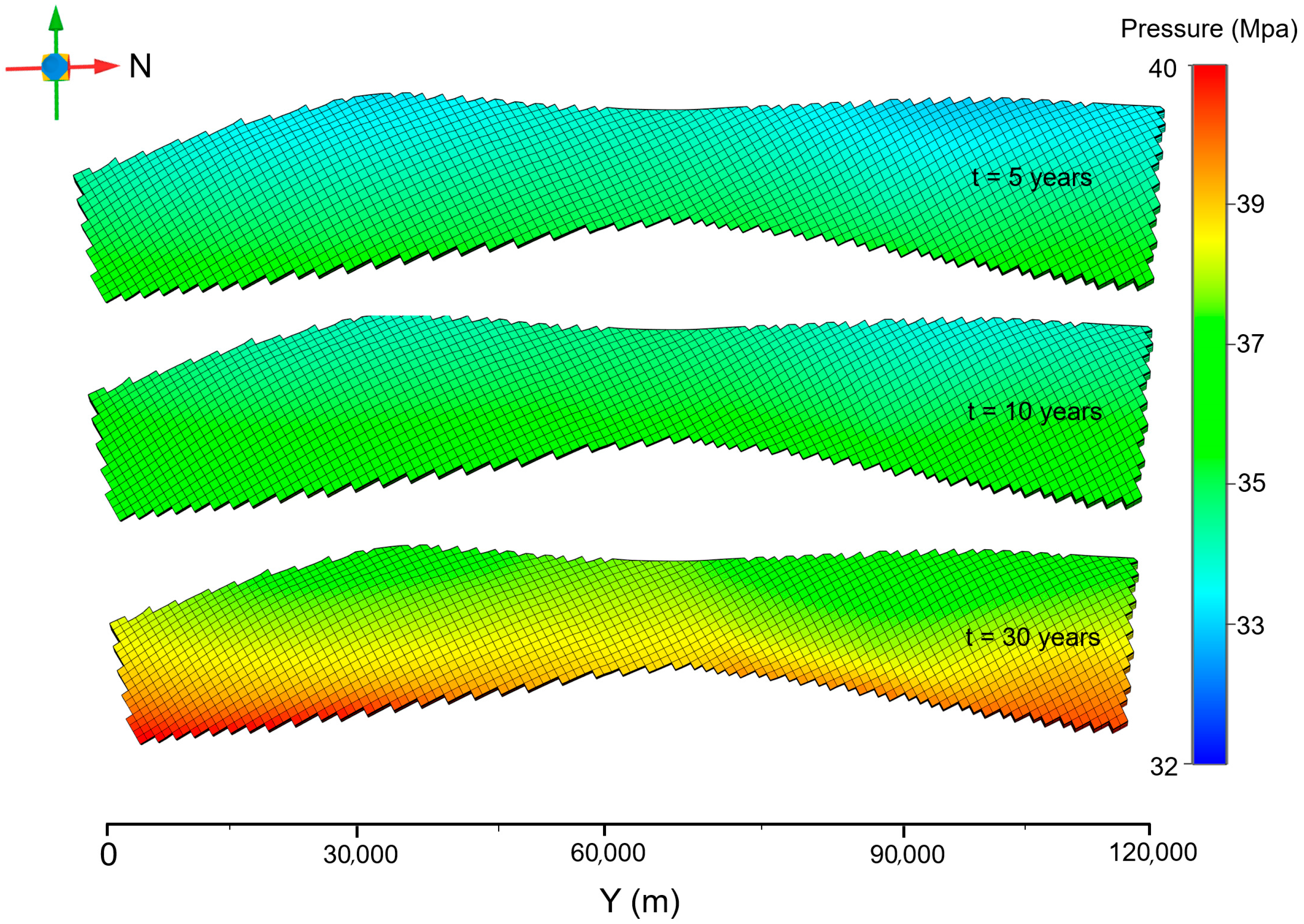
Figure 8 illustrates the spatiotemporal evolution of reservoir pressure under normal operating conditions across different injection durations. The spatial pressure distribution demonstrates a strong positive correlation with the CO
2 plume dispersion pattern. At the 5-year injection period, the maximum reservoir pressure reaches 36.5 MPa, escalating to 37.8 MPa after 10 years of continuous injection. Upon reaching 30 years of sustained injection, the formation pressure peaks at 39.7 MPa. Notably, short-term injection (<5 years) induces minimal pressure deviation from initial formation conditions, whereas the 30-year injection duration triggers a marked pressure surge in the eastern sector. This results in a distinct west-to-east pressure gradient, consistent with the reservoir’s intrinsic permeability anisotropy.
The reservoir exhibits ultra-low water saturation characteristics (ranging from 6.6% to 12.6%), significantly suppressing geochemical reaction intensities under current conditions. Because of the unique carbonate reservoir in the study area, numerical simulation was used to investigate the effect of the CO
2 water–rock reaction process on the amount of CO
2 leakage via the cap rock, as shown in
Table 7.
From
Table 7, it can be seen that the partial CO
2 leakage from the caprock after the addition of the water–rock reaction is slightly less than that from the cap without the addition of the water–rock reaction. Considering that some of the CO
2 may dissolve simultaneously, it is assumed that part of the CO
2 also passively participates in the mass consumption of the water–rock reaction process, which reduces the mass of gas diffused into the caprock, and the amount of CO
2 leakage from the caprock may be reduced. The average annual change in the leakage mass of the two is less than 0.1 t over a longer reaction time, which is a very small error compared to the uncertainty of the real situation over a long-time scale simulation. Therefore, it can be assumed that the CO
2–water–rock chemical reaction has a relatively small impact on the caprock. For this reason, water–rock interactions were excluded from the analytical framework due to their negligible thermodynamic impact.
3.4. CO2 Leakage Under Different Leakage Scenarios
3.4.1. Spatial Distribution of CO2 Under Different Scenarios
The CO
2 distribution at the top of the reservoir under the wellbore leakage scenario is shown in
Figure 9. The maximum north–south migration distances show minimal variation from those under normal operating conditions; however, significant divergence is observed in both the maximum CO
2 mole fraction value and the spatial distribution patterns of high-concentration CO
2 accumulation zones during equivalent operational timeframes. According to the simulation results, 5 years after CO
2 injection begins, the CO
2 gas fraction in the fracture network of the reservoir appears to be significantly increased due to the presence of fractures in the injection well. The maximum mole fraction is only about 0.8. In contrast, there is no large-scale high-concentration CO
2 accumulation zones at the top of the reservoir. After 10 years of injection, the CO
2 shows a tendency to diffuse from the fracture to the surrounding area and the maximum fraction increases to 1.0. When the gas injection time reaches 30 years, the gas concentration in most of the grid appears to increase sharply, and the high gas concentration zone is concentrated near the two injection wells, showing a migration trend from a low concentration in the west to a high concentration in the east. The CO
2 migration area expands to an impressive 1100 km
2.
When compared to the no fracture control group, the presence of fractures in the injection well may reduce the concentration of gas components in the original migration grid. However, excessive gas concentrations concentrated near the fracture can lead to a greater susceptibility to excessive gas pressures at specific points, increasing the risk of caprock breach at particular points.
The CO
2 distribution at the top of the reservoir in the caprock leakage scenario is shown in
Figure 10. The maximum north–south migration distances demonstrate minimal variation from those under normal operating conditions. By comparing the simulation results, it is found that the damage to the caprock caused by faults has less influence on the distribution of CO
2 gas in the reservoir. The spatial distribution of CO
2 is basically the same as the normal working condition.
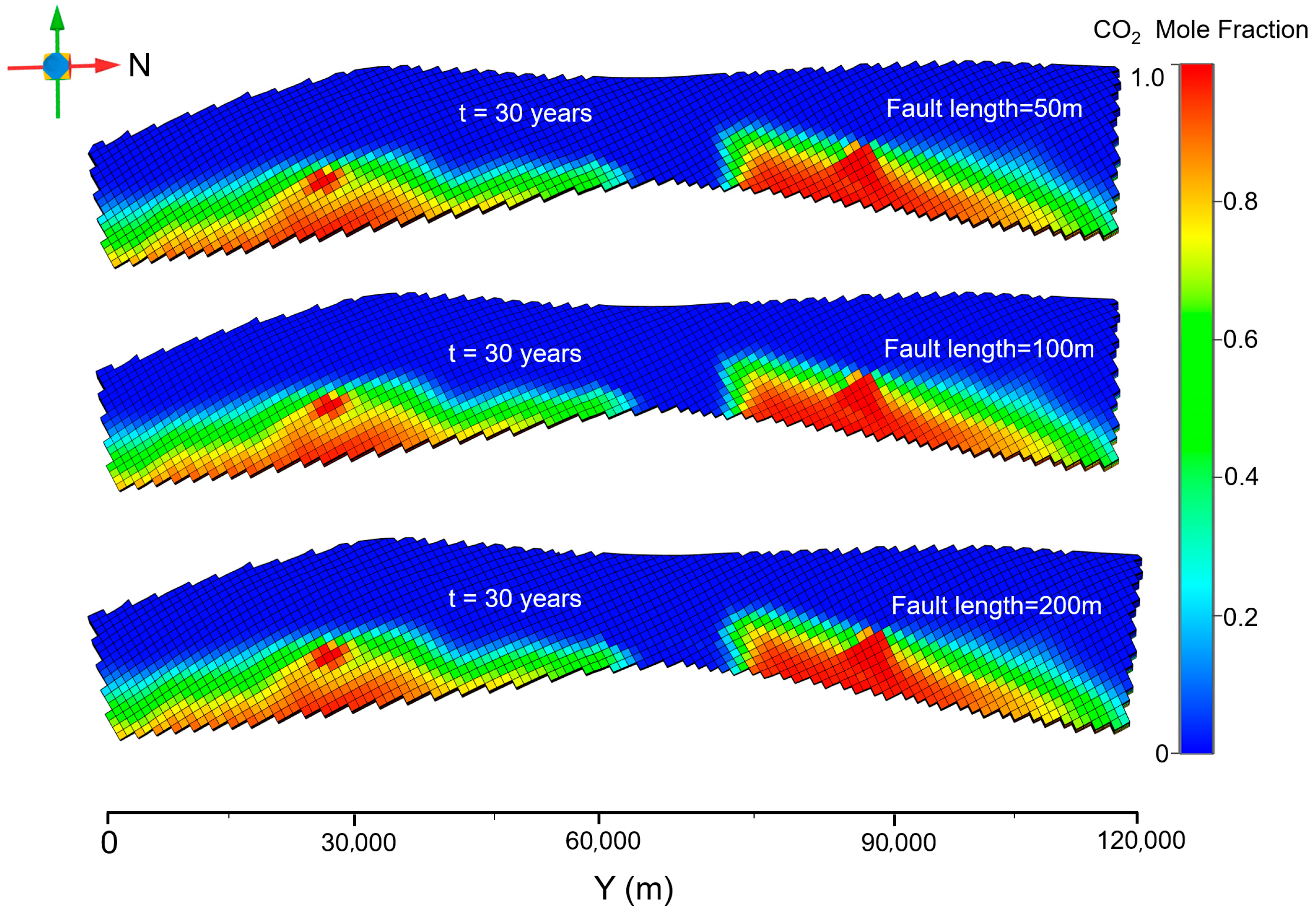
The CO
2 distribution at the top of the reservoir in the fault leakage scenario is shown in
Figure 11. After 5 years of gas injection, the total amount of injected gas is small, and the presence of new faults buffers the high-pressure area generated by the gas injection. The concentration of CO
2 components decreases significantly in the area close to the new fault, presumably because the presence of the fault promotes gas migration to the surrounding grids and the upper caprock. After 30 years of gas injection, the CO
2 content in the grid at the top of the reservoir near the injection well area increases significantly. The decrease in gas content in the fault grid indicates that this part of the gas has already diffused into the upper caprock, which increases the possibility of gas leakage from the cap layer.
3.4.2. Leakage Capacity of CO2 via the Caprock Under Different Leakage Scenarios
The results of the CO
2 leakage calculations for the caprock section are shown in the
Table 8. The presence of fractures in the injection wells exacerbates the process of CO
2 leakage in the caprock formation, and the amount of leakage generated by a small volume of fractures is extremely large, far exceeding that of the control group by a factor of 600. Moreover, the presence of new faults does not have a significant effect on CO
2 leakage in the caprock. Even with an injection time of up to 30 years, the difference is very small. As long as reservoir faults do not disrupt the upper caprock, some smaller-scale additions to the reservoir area will not affect the caprock’s sealing capacity.
As shown in
Figure 12, a more accurate quantitative assessment of the gas leakage is provided. During the 30 years injection period, the CO
2 leakage in the experimental group is up to 160–320 times higher than that of the control group. It can be seen that the gas leakage increases sharply as the injection time increases, and the length of the flaw extending into the caprock also affects the leakage amount. When the fault destroys the entire caprock, the integrity and sealing of the cap layer will no longer exist.
3.5. Sensitivity Analysis
The sensitivity analysis of the simulation in this paper is mainly divided into two categories: a sensitivity analysis of the actual site and a sensitivity analysis of the leakage path. For the verification of the actual site model, this paper fully investigated the geology data, constructed the regional scale model based on the actual stratum conditions, and completed accuracy verification of the model based on the historical production data. It can be considered that the model parameters are fully applicable to the actual site.
Secondly, this paper focused on the main leakage path in the geological storage process. After establishing the model, the representative leakage situation was selected for simulation prediction. The prediction results also further reflect that the caprock is the dominant factor determining storage risk. Other model parameters were less sensitive to the overall storage, which verifies that the evaluation scoring mechanism established in this paper is feasible.
3.6. Leakage Risk Assessment of the Wolonghe CO2-EGR Project
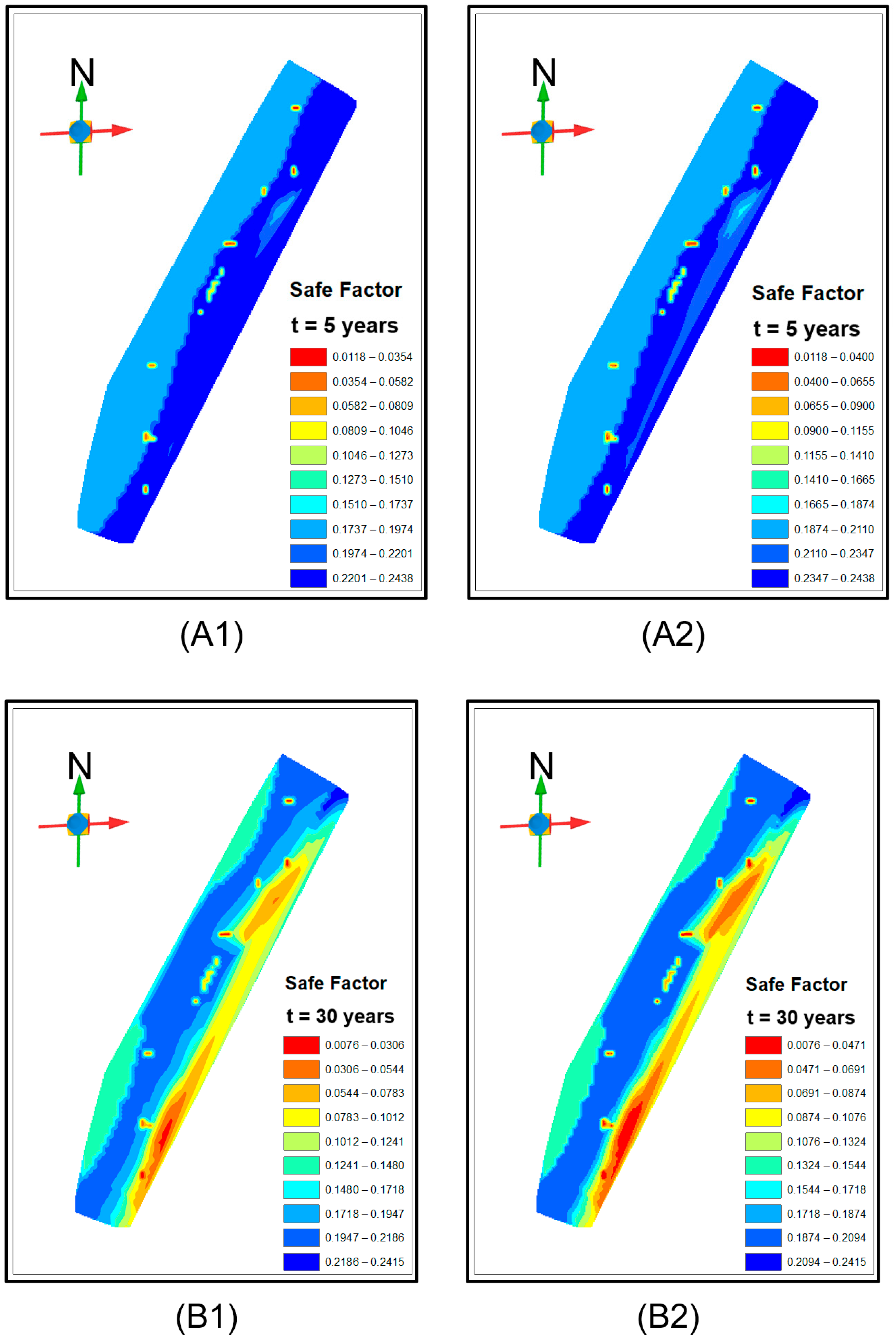
On the basis of the different working stages of the injection and extraction wells in the actual sequestration process, the leakage risks at 5 years after the start of injection (2027) and 30 years after the expansion of the injection volume (2053) were calculated and the corresponding risk grading diagrams were drawn.
According to the leakage rating method in
Table 6, a higher score indicates a safer containment process. Areas with a risk score greater than 0.1 have a low risk of leakage and are acceptable under normal working conditions. Conversely, areas with a risk score of less than 0.1 have a higher potential risk of leakage.
With an injection time of 5 years, the potential leakage risk is mainly located in the vicinity of the W83 and W93 wells, which were analyzed due to the poor cementing quality of the W83 wells, and there is a risk of leakage along the wellbore. Another potential risk point is near the W47 well, where poor cementing quality in the B and C annulus of the well increases the risk of gas leakage. In addition, the risk of leakage around the two injection wells is also high, and it is recommended that appropriate monitoring programs be implemented. Overall, the leakage risk is very low under the condition of 5 years of gas injection and the containment is in an ideal sealing condition. However, individual engineering wells may increase the leakage risk in the adjacent area due to the time of well formation and cementing quality. Therefore, it is necessary to strengthen monitoring efforts and take the necessary preventive measures.
In the second stage of extending injections to 2053, the points with potential leakage risk show a regionalized increase, mainly distributed on the eastern side of the study area. The analysis suggests that there are some areas of higher permeability on the east side of the reservoir, forming a dominant permeability path. The process of sequestration promotes further gas migration, which increases the risk of leakage when the caprock is breached. Overall, as storage time and the total amount of injected gas increases, CO
2 will eventually accumulate at the top of the reservoir due to its own buoyancy, significantly increasing the average molar fraction of CO
2 and the formation pressure. Referring to the scoring rules in
Table 2, the overall score is significantly lower compared to 2027, which is consistent with the increased risk of leakage after actual injection. For long-term storage, the high-risk areas shown in
Figure 13 need to be equipped with appropriate monitoring points to track the leakage risk in real time, ensuring that the dangerous situation at individual risk points does not deteriorate, which could lead to a dramatic spread of gas in the local area or even throughout the entire study area.
4. Conclusions
This paper proposed a dynamic assessment method for CO2 leakage risk assessment and applied it to the CO2-EGR project in the Wolonghe gas field, which is the first CO2-EGR pilot project in China. The conclusions are summarized as follows:
(1) Considering the necessity of constructing a numerical model for each CCUS project, a more precise dynamic evaluation method for assessing CO2 leakage risk was developed. A comprehensive evaluation index and a scientific score calculation method were established according to the characteristics of different leakage modes and their influencing factors.
(2) An accurate 3D numerical model of the CO2-EGR project in the Maokou gas reservoir was developed and validated using detailed geological and hydrological data and historical production data. The CO2 leakage risks under different scenarios were evaluated and the results indicated that the CO2 leakage risk was observed to be most pronounced when the caprock integrity was damaged by faults or geologic activities. This was followed by leakage caused by wellbore failures.
(3) According to the dynamic CO2 leakage risk assessment results, this project has a low risk of CO2 leakage, and well stability and existing faults are the major risk factors in the short term. However, reservoir permeability and porosity take turns in dominating the leakage risk over the long term (e.g., 30 years). The eastern part of the study area was classified as a leakage-prone area due to the existence of high-permeability strata. Because the CO2 leakage risk and critical risk factors dynamically change with time, a monitoring program needs to be dynamically deployed in conjunction with different time periods.
This study innovatively combined numerical simulation results with quantitative evaluation scoring indices, realizing directional feature application of the evaluation method. It also investigated dynamic relationships between the distribution of the CO2 plume and the amount of leakage over a longer time scale. However, there is still a need for more accurate and specific descriptions of the leakage paths, such as the wellbore and faults, etc. The established method of cumulative multiplication of comprehensive indexes cannot accurately reflect the weight influence of each index on the overall leakage risk. In the future, more attention should also be paid to the deformation mechanism of fractures during the sealing process in the evaluation system.
