Review

Self-Sustaining Operations with Energy Harvesting Systems

by
Peter Sevcik
,
Jan Sumsky
,
Tomas Baca
and
Andrej Tupy
*
Department of Technical Cybernetics, Faculty of Management Science and Informatics, University of Zilina, 01026 Zilina, Slovakia
*
Author to whom correspondence should be addressed.
Energies 2025, 18(17), 4467; https://doi.org/10.3390/en18174467
Submission received: 15 July 2025 / Revised: 4 August 2025 / Accepted: 6 August 2025 / Published: 22 August 2025

Abstract

Energy harvesting (EH) is a rapidly evolving domain that is primarily focused on capturing and converting ambient energy sources into more convenient and usable forms. These sources, which range from traditional renewable sources such as solar or wind power to thermal gradients and vibrations, present an alternative to typical power generation. The temptation to use energy harvesting systems is in their potential to power low-power devices, such as environment monitoring devices, without relying on conventional power grids or standard battery implementations. This improves the sustainability and self-sufficiency of IoT devices and reduces the environmental impact of conventional power systems. Applications of EH include wearable health monitors, wireless sensor networks, and remote structural sensors, where frequent battery replacement is impractical. However, these systems also face challenges such as intermittent energy availability, limited storage capacity, and low power density, which require innovative design approaches and efficient energy management. The paper provides a general overview of the subsystems present in the energy harvesting systems and a comprehensive overview of the energy transducer technologies used in energy harvesting systems.

1. Introduction

Modern civilization is highly dependent on electrical energy. We use it in every area of our lives, from simple home appliances to large machines in factories.
The conventional power systems are classified into two major categories:
  • Fossil fuel power plants generate electrical energy by burning fossil fuels, which generates heat that changes the pressurized water into steam, which is used to power the steam turbine used for electrical energy generation.
    Their primary disadvantage is the pollution caused by the burning of fossil fuels, which releases into the atmosphere large quantities of greenhouse gases, which cause global warming, and other health-damaging substances.
    Furthermore, fossil fuels are a non-renewable energy source, at least on the human time scale, since their creation takes millions of years. As a consequence, the fossil fuel power plant does not represent a long-term solution to the energy generation problem.
  • Nuclear power plants use the process of nuclear fission, in which a heavier atom accepts a neutron into its atomic structure, which leads to a change in its state from stable to unstable—it becomes a different isotope of the same chemical element whose nucleus is unstable. The unstable isotopes are capable of only a short time of existence, after which the heavy atom (its unstable nucleus) splits into two lighter atoms (two different stable nuclei). During nuclear fission, a large amount of thermal energy is released, which is used to heat the pressurized water. From now on, the energy generation process is the same as with fossil fuel power plants. The primary difference is in the source of thermal energy.
    The nuclear power plants do not cause problems with pollution like fossil fuel power plants. However, during their operation, the radioactive waste, primarily in the form of spent (burned-out) nuclear fuel, is produced.
    In the past, the primary problems were the long-term storage and transportation of the spent nuclear fuel, which stays highly radioactive after the nuclear fission. And the catastrophic consequences associated with nuclear catastrophes, such as the ones in Chernobyl and Fukushima.
    The current solution for the long-term storage of spent nuclear fuel uses disused mining shafts or similar underground cavities, usually located in remote areas where radioactive material can be safely stored. For transportation, specialized, highly durable containers that prevent the contamination of the environment in the case of an accident are used.
    Furthermore, the new generation of nuclear reactors and highly improved security standards and regulations limit the possibility of another nuclear catastrophe.
The renewable energy harvesting systems represent an environmentally friendly alternative to the conventional power systems. They use the ambient energy that would otherwise be wasted and convert it into usable electrical energy.
Large-scale energy harvesting systems use natural renewable energy sources, such as solar energy harvested by photovoltaic panels or kinetic energy in the water or wind movement harvested by hydroelectric generators and wind turbines.
Small-scale energy harvesting, also known as power harvesting or energy scavenging, is a cutting-edge field of research that focuses on the capture of relatively small amounts of energy from various ambient energy sources in the environment.
This process involves converting these ambient energy sources—often considered insignificant or residual—into usable electrical power.
The primary objective of energy harvesting is to provide a sustainable, efficient, and often self-sustaining power supply for low-energy devices, particularly in situations where conventional power sources are unavailable.
The concept of energy harvesting is a crucial step towards more sustainable and environmentally friendly energy solutions in the near future. By tapping into the ambient energy that surrounds us—from the heat emitted by machines to the vibrations generated by processes in nature—energy harvesting technologies aim to reduce the dependency on standard batteries and external power sources, thereby minimizing electronic waste and the environmental footprint of the system.
This approach is particularly valuable for powering small, mostly wireless and autonomous IoT devices, such as those used in wearable electronics, medical implants, and sensor networks in nature.
Recent advancements in energy-harvesting technologies predict a promising future for self-powered IoT electronic devices, enabling their use in remote wilderness areas without easy access to the conventional power grid.

2. Energy Harvesting System

An energy harvesting system, by design, is capable of capturing ambient energy from the environment and converting it into usable electrical energy. The implementation of an energy harvesting system can vary depending on the energy source harvested. In general, these systems are composed of several key components, as shown in Figure 1, that work together to collect, convert, store, and manage energy [1,2,3,4].
The key components of a generalized energy harvesting system are:
  • Energy transducer,
  • Energy storage,
  • Power management circuit,
  • Control and monitoring circuitry,
  • Load (end-use application).
Each component of this system plays a crucial role in ensuring efficient capture, conversion, and utilization of ambient energy. The integration and optimization of these components are key factors in the effectiveness and viability of the system. As technology advances, improvements in materials, circuit design, and energy storage technologies continually enhance the performance of energy harvesting systems. The discovery of new ways to extract residual energy from natural processes is an ongoing and perhaps endless task for researchers.
In this article, we focus mainly on the different types of energy transducers used in energy harvesting systems. We describe their working principles, possible applications, their advantages and disadvantages, and current research goals. However, modern energy harvesting systems often times use different transducers together to increase the amount of harvested electrical energy. These are called the hybrid energy harvesting systems [5].

Artificial Intelligence and Machine Learning in Energy Harvesting

Artificial Intelligence (AI) and Machine Learning (ML) are promising new technologies that enhance the possibilities of energy harvesting systems. The biggest challenge in the "non-intelligent" implementations of energy harvesting systems lies in the predictability and availability of ambient energy sources. These challenges can be addressed by using the ability of AI and ML-trained models to predict the behavior of energy sources. Additionally, these technologies offer several advantages for optimizing energy harvesting system performance, managing energy storage, and predicting energy consumption needs.
AI and ML algorithms can analyze patterns in energy generation and usage, enabling them to predict future energy availability and demand. Their usage is particularly valuable for harvesting systems reliant on variable energy sources, where the use of conventional energy storage solutions like batteries is not practical or even possible [6,7].

3. Energy Sources

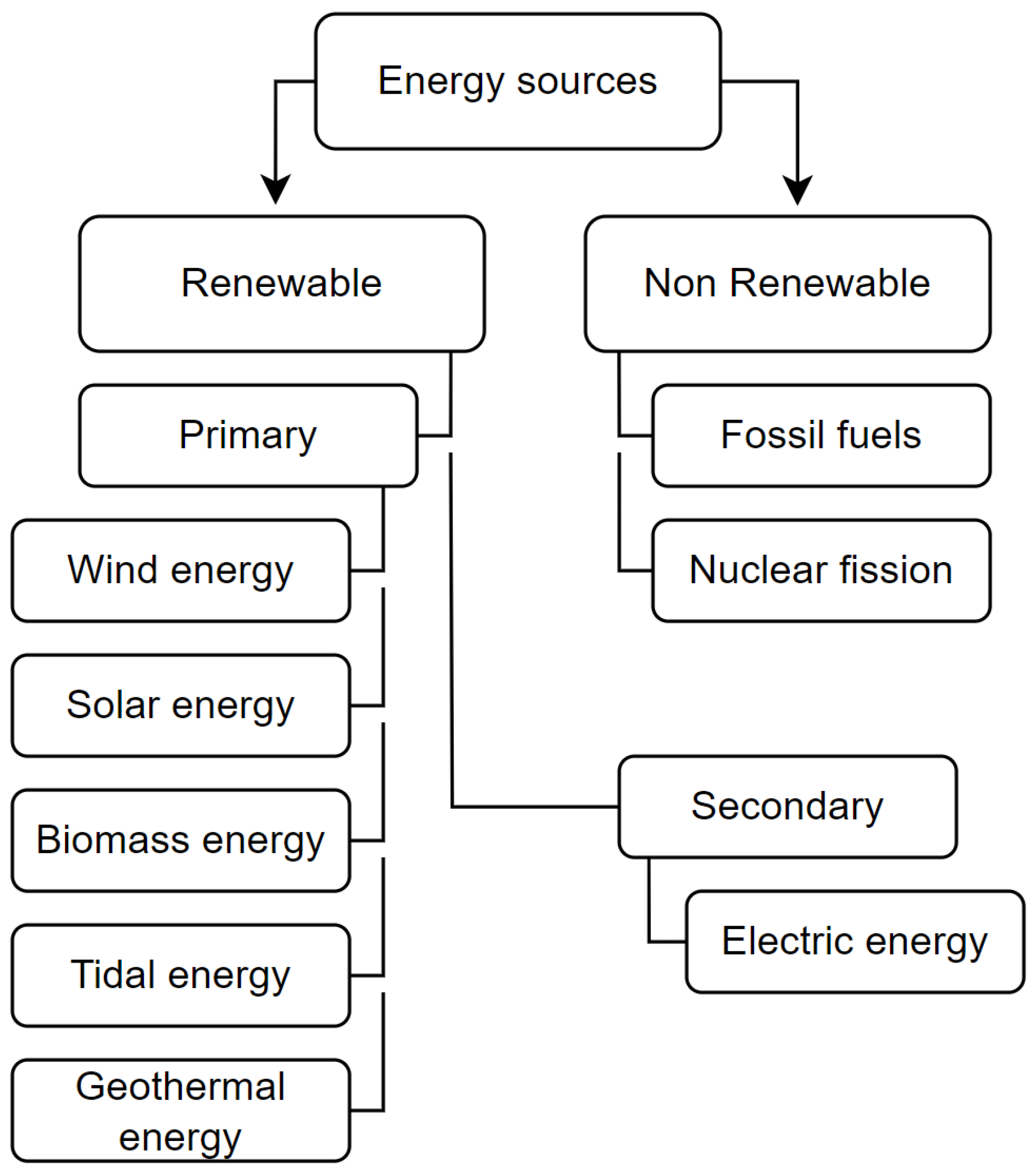
An energy source is any substance or system that can provide a significant amount of energy in a useful form. These sources can be simply categorized based on their property of replenishment as non-renewable and renewable sources; see Figure 2. Another way to categorize them is by the predictability, which refers to the ability to estimate the availability and behavior of the energy source. This categorization gives us predictable and unpredictable energy sources. Lastly, we can differentiate energy sources into primary and secondary energy sources [8,9,10,11].

3.1. Non-Renewable Energy

Non-renewable Energy (NRE) sources exist in finite quantities and can be depleted. Once used, they cannot be readily replenished on a human timescale. In general, NRE sources tend to have a greater environmental impact, including greenhouse gas emissions that cause global warming and other forms of pollution [12,13].
The best example of an NRE source is fossil fuels, which have formed over billions of years due to pressure and temperature acting on animal and plant remains. These fossil fuels are presently utilized for combustion engines, heating applications, and various other purposes.
NRE sources also have a bad effect on the ecosystem in the areas where they are collected.
For example, oil spills may occasionally occur during the extraction or transportation of petroleum in marine environments. Such spills lead to the formation of an oil layer on the water’s surface, posing a significant threat to marine wildlife and seabirds. Even physical contact with the oil can cause serious harm, and ingestion may ultimately result in death [14].
Another example could be oil mining in the Amazon rainforest; during this process, big chimneys are burning up the exhaust gases from the oil extraction. The dangerous chemicals contained in this smoke pollute the rainwater in the clouds, which then, in turn, pollutes the entire ecosystem during rainfall. This phenomenon is called acid rain. As a result, the primary source of water for the plants, animals, and humans around the mining areas is polluted by the heavy metals and other by-products of the mining process. Blood tests conducted on members of the local tribes revealed elevated levels of heavy metals such as cadmium and mercury [15].
The last example of an NRE source is nuclear energy. Nuclear fuel cannot be replenished, and although nuclear fission appears to release no greenhouse gases, the final storage of burnt fuel remains a significant environmental concern since the used nuclear fuel can remain radioactive for centuries or even millennia after it was used. The current approach for storing this radioactive waste is to use old mines located deep underground [16].

3.2. Renewable Energy

Renewable Energy (RE) sources are those that are continuously replenished by natural processes and can be used indefinitely without the risk of depletion. These sources are generally more sustainable as they have minimal impact on the environment. Such sources produce little to no amounts of greenhouse gases and air pollutants during the whole conversion process to electrical energy. As a result, their contribution to climate change or destruction of the environment is minimal [17,18,19].
Renewable energy sources are commonly classified into two groups: primary energy sources and secondary energy sources.
Primary sources are the energy sources created by some natural phenomena. The energy is in its natural form and has not been transformed or converted into another form.
Secondary sources, on the other hand, are energy sources derived from the conversion or processing of primary energy sources. Their energy is usually in the form of electrical energy, which can be directly used or stored for later use.
Understanding the distinction between primary and secondary RE sources is important for comprehending how energy transitions from its natural state to a form that is more readily usable in various applications. Primary sources provide the initial form of energy, while secondary sources result from further processing or conversion of this energy.
Common examples of renewable energy sources are photovoltaic energy from the sun, kinetic energy from the wind and water movement, geothermal energy from the earth’s core heat, and biomass energy from plants and organic waste.
The RE power plants can be used to generate substantial amounts of electricity and can provide sufficient power to supply entire cities or even states.

3.3. Ambient Energy

Ambient Energy (AE) refers to all forms of low-grade energies available only in small quantities that are freely available in our immediate environment [20,21,22,23,24].
Ambient energy is omnipresent in the environment, often as a by-product of natural or human-made processes. Thus, the sources of ambient energy can be both RE sources caused by natural processes and NRE sources caused, for example, by industrial processes.
Not all sources of ambient energy are environmentally friendly, for example the harvesting of vibrational energy.
It is possible to harvest vibrational energy from vibrations caused by the functioning of a large diesel engine. However, this engine uses diesel as fuel, which is an NRE source. Thus, this ambient energy source is not considered environmentally friendly since the basic non-renewable ingredients from which the diesel is made need to be mined and processed. Furthermore, through the operations of this diesel engine, greenhouse gases are released into the atmosphere, which contribute to global warming.
We can also harvest the vibrational energy from naturally occurring processes, such as weak earthquakes, the movement of waves in the ocean, or the movement of trees. During these processes, no greenhouse gases or other pollutants are released into the atmosphere. Thus, in these circumstances, we can consider the harvested vibrational energy to be environmentally friendly.
The AE can also be obtained from sources such as temperature gradients caused by the residual heat in the atmosphere, electromagnetic energy from electromagnetic waves, naturally occurring vibrations, or photovoltaic energy obtained from ambient lights. The ambient energy sources are sometimes in the form of weakly damped systems, which causes problems with their collection [25].
The AE sources can be used to power low-power applications, such as small electronic devices, sensors, and Internet of Things (IoT) devices.

3.4. Ambient vs. Renewable Energy

Both AE and RE sources contribute to sustainable energy solutions. They differ in scale, intensity, application, and the technology used for their harnessing and utilization. AE focuses on harnessing small-scale omnipresent energy in our environment, while RE involves more abundant natural resources that can be continuously renewed.

3.5. Energy Sources Usage in the Past and Future

In Figure 3, the past usage of different energy sources is shown from 2000 and the prediction of the trend of usage of energy sources until 2050 [26,27,28].
In the year 2000, the majority of energy was generated by non-renewable energy sources, coal, gas, oil, and nuclear power plants. The only renewable energy source was hydroelectric energy from hydroelectric (water) dams.
However, as we progress towards the year 2050, we can see a predicted decrease in the use of non-renewable energy sources and their replacement with renewable energy sources such as photovoltaic (solar) energy or wind energy, both onshore and offshore.
Figure 3 shows the increase in the demand for electrical energy in the past and its prediction in the future.
This figure focuses on the major RE sources for electricity generation that have the capacity to power entire cities or even states.
However, the AE harvesting systems can also be used on a far smaller scale, such as powering different sensors with very small energy consumption and thus prolonging their lifespan.
This is the area that has been given more attention over the last few years because of the constant increased usage of this type of low-power device, caused by the increasing popularity of IoT applications.
Considering that these devices have small energy consumption, their numbers are rapidly growing. As a result, their combined energy consumption is a significant portion of the worldwide energy consumption, and if this trend lasts, then this portion will be constantly growing.

4. Energy Transducer

Transducers, also known as energy converters, are devices that incorporate various physical principles and technologies to convert different forms of primary energy into secondary (electrical) energy. The technology behind these transducers is as diverse as the energy forms they harness.
The essential characteristics, capabilities, and parameters common to most transducers include:
  • Conversion efficiency—the proportion of input energy that is successfully converted to electrical energy.
  • Power density—the amount of power generated per unit of volume or weight of the transducer mechanism. Most important for wearable implementations.
  • Response time—the time that the transducer takes to respond to changes in the input energy.
  • Durability—the ability of the transducer to resist conditions in the environment where it is supposed to be used.
  • Operation time—can be determined in consideration of durability and maintenance cycles.
  • Sensitivity—magnitude of the change in output quantity in response to a known change in the input quantity.
  • Scalability—how easily the transducer can be used on a large scale.
  • Environmental impact—mostly evaluated based on the materials used and the interference of the transducer with the environment, such as noise and vibrations.
The values of the parameters mentioned above strongly depend on the quality standards of the different manufacturers of the transducers and also on the application in which the transducers are supposed to be used.
In the following subsections, we will explore the current most commonly used transducer implementations.

4.1. Photovoltaic Cell

4.1.1. Working Principle of Photovoltaic Cells

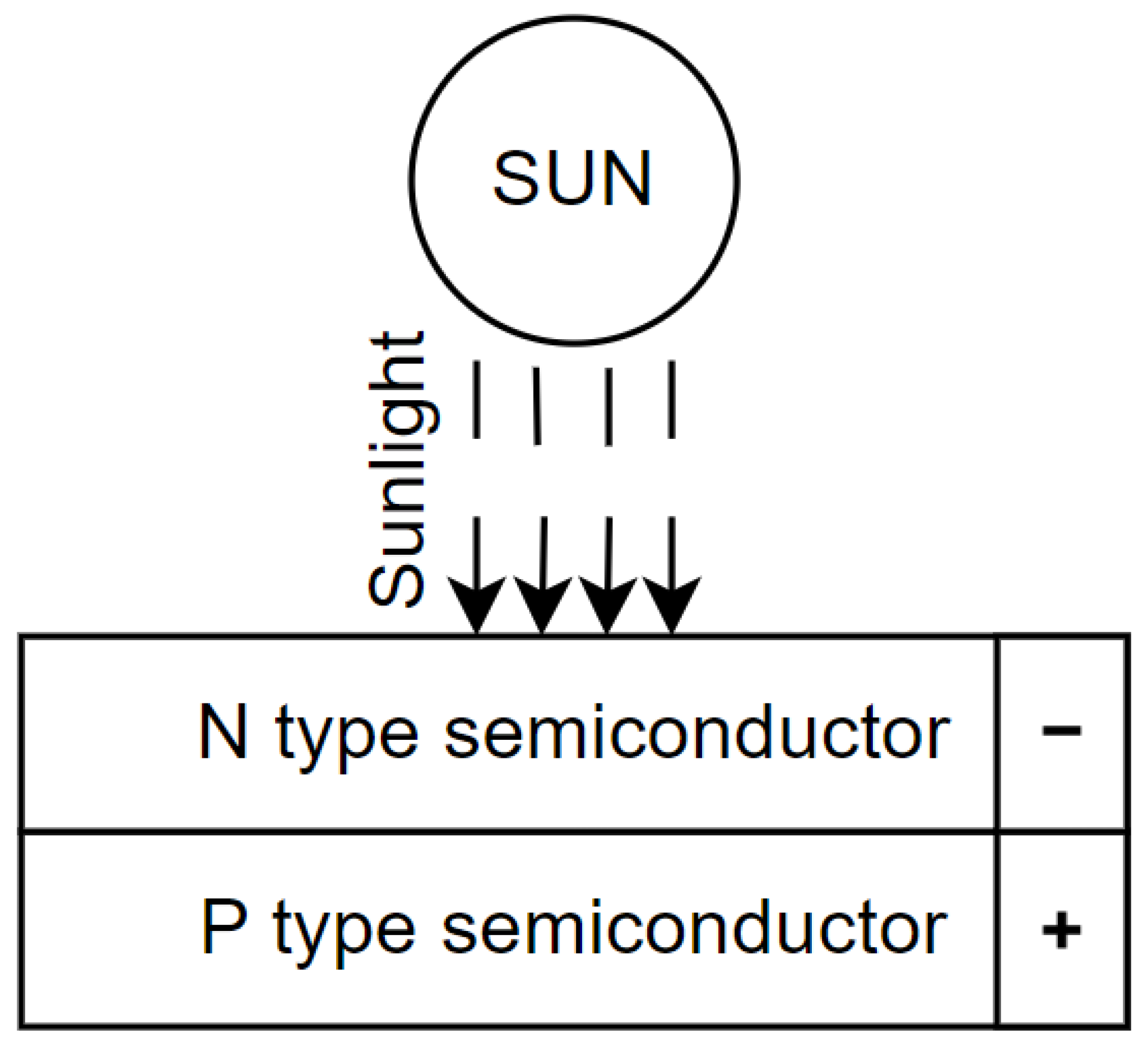
A photovoltaic cell-based energy transducer converts solar energy, including visible and infrared light, into electrical energy using the photovoltaic effect, as illustrated in Figure 4. In this process, light photons, loaded with energy, collide with a semiconductor material, usually silicon [29,30,31,32].
This impact energizes the electrons within the silicon crystalline structure, causing them to break free from their atomic bonds and move freely. These free electrons, driven by internal electric fields within the semiconductor material, create a flow of electrical charge.
The semiconductor material is usually layered between conductive materials (electrodes), forming a pathway for this current to be collected and directed to an external circuit.
This circuit then transports the generated electrical energy into various applications.
Photovoltaic cells generate a Direct Current (DC) as their output. Therefore, the output voltage of the photovoltaic panels needs conversion to match the levels required by the load.

4.1.2. Conversion Efficiency and Power Density of Solar Energy

The efficiency of the photovoltaic cells tells us how much of the absorbed sunlight the photovoltaic cells convert into electrical energy through the photovoltaic effect [33].
Solar panels have a high lifespan; however, their efficiency is slowly decreasing with time. The National Renewable Energy Laboratory (NREL) defines this drop in the solar panel efficiency as the degradation rate of the semiconductor materials.
The power density of photovoltaic cells is usually measured in watts per square meter ( Wm 2 ). It tells how much electrical energy can be produced by a photovoltaic panel of the size of 1 square meter.
To calculate the total power production per day, it is crucial to find out how many hours per day the sun is shining, and then we can calculate how many watts per hour (Watt-hour (Wh)) the photovoltaic panel is capable of producing.
Photovoltaic cells have a very fast response time on the order of hundreds of microseconds.

4.1.3. Types of Photovoltaic Cells

Crystalline and thin-film photovoltaic cells are the two currently most used types in real-life applications.
Crystalline photovoltaic cells are divided into monocrystalline silicon and polycrystalline silicon photovoltaic cells [34].
Monocrystalline silicon photovoltaic cells are:
  • Made with the Czochralski process [35],
  • Composed of a single, continuous crystal lattice with no grain boundaries,
  • More efficient because of the uniform structure, which allows the electrons inside the silicon ingots to move more freely,
  • Mostly black in color,
  • More expensive to produce because of the complex manufacturing process,
  • Commonly used in high-efficiency solar panels,
  • Have a long lifespan, reaching up to 40 years,
  • Have a conversion efficiency between 15% and 24%,
  • Have a power density ranging from 150 to 200 Wm 2 ,
  • Have a 0.14% drop in efficiency per year of their operation (as 100% efficiency was considered the normal efficiency for this type of solar cell), based on tests performed by NREL,
  • The most commonly used type of crystalline photovoltaic cells and photovoltaic cells in general.
Polycrystalline silicon photovoltaic cells are:
  • Made with the chemical vaporization deposition process,
  • Made of multiple small silicon crystals or grains, which can create grain boundaries,
  • Less efficient than single-crystal silicon ingots because of the presence of grain boundaries that decrease the flow of electrons inside the silicon ingot,
  • Mostly blue in color,
  • Less expensive to produce thanks to the simpler manufacturing process,
  • Commonly used in low-efficiency solar panels,
  • More sensitive to high temperatures, at which their efficiency decreases compared to monocrystalline silicon photovoltaic cells,
  • Have a lower lifespan, reaching up to 35 years,
  • Have a conversion efficiency between 13% and 16%,
  • Have a power density ranging from 150 to 180 Wm 2 ,
  • Have a 1% drop in efficiency per year of their operation (as 100% efficiency was considered the normal efficiency for this type of solar cell), based on tests performed by NREL.
Thin-film photovoltaic cells are divided into amorphous silicon and cadmium telluride (CdTe) photovoltaic cells [36]. The main advantage of thin-fill panels is their low cost and flexibility, which allows them to be used in places where the crystalline photovoltaic cells cannot. Their efficiency is also less affected by high temperatures.
Their main disadvantages are their lower efficiency, lower lifespan, and lower durability in comparison with crystalline photovoltaic cells.
The properties of cadmium telluride photovoltaic cells include the following:
  • The most widely used type of thin-film photovoltaic cells is the second most widely used type of photovoltaic cell in general.
  • They have a conversion efficiency between 12% and 13%.
  • They have a lifespan reaching 25 to 30 years.
  • Based on tests performed by NREL, these cells have a 0.45% drop in efficiency per year of their operation (as 100% efficiency was considered the normal efficiency of this type of solar cell).
  • Commercially used cadmium telluride photovoltaic cells have a power density ranging from 100 to 150 Wm 2 .
The properties of amorphous silicon photovoltaic cells:
  • They have a conversion efficiency between 6% and 9%.
  • They have a useful life of 10 to 20 years.
  • Based on tests performed by NREL, these cells have a 1 to 2% drop in efficiency per year of their operation (as 100% efficiency was considered the normal efficiency of this type of solar cell).
  • Commercially used amorphous silicon photovoltaic cells have a power density ranging from 60 to 100 Wm 2 .
Both cadmium telluride and amorphous silicon are toxic substances to humans if they are ingested or inhaled.
The one problem associated with the conversion efficiency and power density is the angle at which the sunlight hits the photovoltaic cell; this angle is known as the angle of incidence. The conversion efficiencies of solar cells are measured when sunlight hits the surface of the panel perpendicularly. However, as the angle changes, the efficiency decreases, and thus even the power density decreases.
Because of this, solar tracking mechanisms are used. They allow the solar cells to have high conversion efficiency throughout the day. Their task is to follow the Sun by measuring its intensity and rotating the solar cells so that they are facing the Sun directly throughout the day [37].

4.1.4. Concentrated Photovoltaic Cells

Concentrated Photovoltaic Cells (CPV) are a new type of cell that is becoming increasingly popular. A CPV uses the mirrors to significantly increase the amount of solar energy that hits the solar cell [38].
However, as more solar energy reaches the solar cell, its temperature increases, which in turn reduces its conversion efficiency. Therefore, in order to keep the conversion efficiency high, we need to cool the CPV.
They are cooled by water cooling, in which cold water is pumped through one internal layer of the CPV itself. This means that the CPV not only generates electrical energy by the photovoltaic effect but also serves as a water heater.
The main advantage is the high conversion efficiency, reaching 41%.
The main disadvantage is that if the cooling system fails to sufficiently cool the CPV, it may overheat and suffer permanent damage.

4.1.5. Solar Farms

Multiple photovoltaic cells are interconnected to form a solar panel.
Multiple photovoltaic panels are often used together to produce a solar farm.
The biggest solar farm currently, the Xinjiang solar farm, is located in China. This solar farm has an installed power capacity of 5 G W and a power output of 6.09 TWh per year, covering an area of 810 km 2 .
For comparison, the biggest nuclear power plant, the Kashiwazaki-Kariwa plant in Japan, has an installed power capacity of 7.965 MW, covering an area of 4.05 km 2 .

4.1.6. Advantages of Photovoltaic Cells

Continuous improvements in photovoltaic cell conversion efficiency have reduced the number of cells required to generate the same amount of electricity over the past few decades. This decrease, combined with lower production costs of photovoltaic cells, has contributed to a reduction in the overall cost of this energy-harvesting system [39].
Additionally, over the past few decades, the durability of photovoltaic cells in extreme weather conditions has also improved.
Solar energy is the most abundant energy source on the planet. According to the US Department of Energy, an hour and a half of sunlight that reaches the surface of the planet is capable of generating enough energy to meet all of humanity’s energy consumption for an entire year.
One of the key reasons humanity favours renewable energy sources is their minimal or even non-existent carbon footprint. Photovoltaic cells generate energy without emitting pollutants. However, the extraction and processing of materials used in their production do result in some emissions. Nevertheless, over their lifespan, photovoltaic cells have a significantly lower carbon footprint compared to fossil fuels [32].

4.1.7. Disadvantages of Photovoltaic Cells

Building thin-film photovoltaic cells requires some hazardous chemicals and heavy metals. After the photovoltaic cells reach the end of their lifespan, they must be carefully disposed of to avoid harming the environment. According to the International Renewable Energy Agency (IRENA), by the year 2050, old solar energy systems could be responsible for up to 78 million metric tons of waste. This waste cannot simply be placed in landfills; it must be carefully processed to protect the environment [40].
Another issue is that, while solar energy has a minimal carbon footprint, solar plants require significant space. A solar plant able to generate 1 MW of electricity will use approximately 9300 m2 of land.
Photovoltaic cells do not operate with equal efficiency worldwide. The energy output of a photovoltaic cell depends on several factors, including the amount of direct sunlight it receives, the size and number of cells used, their geographic location, and ambient temperature. As a result, in regions with limited sunlight throughout the year, other renewable energy sources may be more effective [32].

4.1.8. Current Research Goals

The research in the area of photovoltaic cells is focused on two main areas.
The first area focuses on photovoltaic cells that utilize organic materials, such as polymers, to convert sunlight into electricity. These cells offer advantages like low production costs and the potential for thin, flexible designs. However, researchers are working to improve their conversion efficiency and durability, which remain lower than those of traditional photovoltaic technologies. These organic photovoltaic cells aim to mimic the natural process of photosynthesis to generate electrical energy [41,42,43,44].
Additionally, research is focused on improving the ability of photovoltaic cells to capture more light and enhance their conversion efficiency. One promising approach is integrating photovoltaic cells with thermoelectric cells, which convert the residual heat generated by the photovoltaic cell into usable electrical energy. However, the primary challenge with this method is the low conversion efficiency of thermoelectric cells [45,46,47].

4.2. Piezoelectric Transducer

4.2.1. Working Principle of Piezoelectric Transducer

The piezoelectric transducer is based on the piezoelectric effect, which is a unique property of certain materials, e.g., crystals and specific ceramics [48,49,50,51,52,53].
The piezoelectric effect can be utilized in two main modes, i.e., direct and opposite piezoelectric effect.
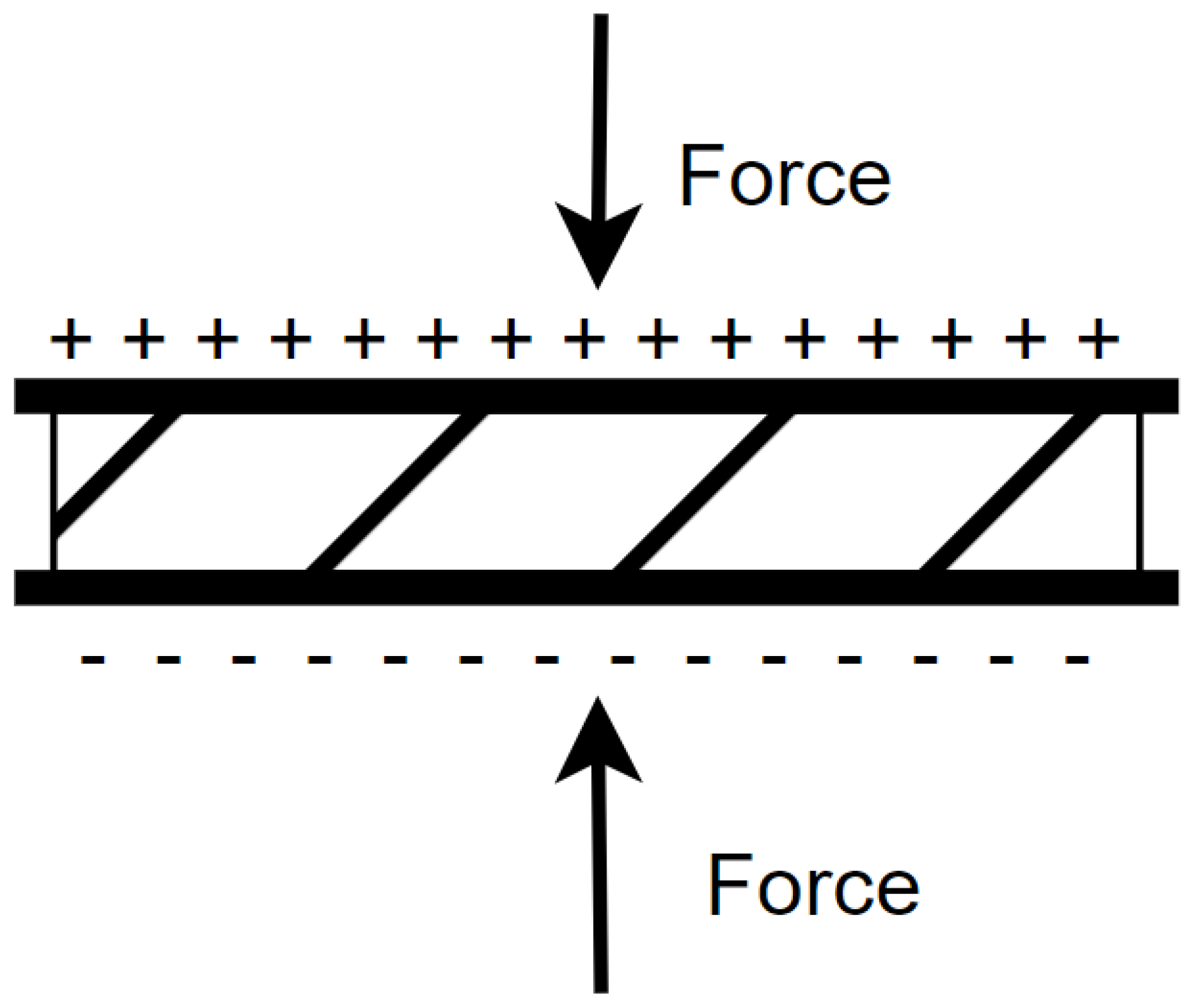
The direct piezoelectric effect shown in Figure 5 generates an alternating electric charge in the piezoelectric materials under mechanical stress. This phenomenon allows the transducer or sensor to convert mechanical energy, such as pressure, oscillation, and vibration, into electrical energy.
The opposite piezoelectric effect causes a change in shape or size of the piezoelectric material when an electric field is applied to it. This phenomenon allows piezoelectric materials to act as actuators that can produce mechanical force or motion.
The reversible property of piezoelectric materials makes them suitable for use as sensors, actuators, and transducers.
As sensors, they can detect and convert various forms of mechanical stress into electrical signals. This is useful in applications such as pressure sensing or vibration monitoring. Examples of these applications are piezoelectric microphones or ultrasonic devices used in medical imaging.
As actuators, they are used to create precise movements or vibrations, as seen in medical ultrasound devices or precision control mechanisms.
As transducers, they are used to harvest pressure and vibrations caused by natural or industrial processes and transform them into electrical energy that is either directly used or stored for later use.
The piezoelectric material is usually layered between conductive materials (electrodes), forming a pathway for the electric charge to be collected and directed to an external circuit.
This circuit then transports the generated electrical energy into various applications.
The piezoelectric transducer is capable of generating an electrical voltage proportional to the rate of change in the applied stress.
Piezoelectric transducers generate an alternating voltage at their output, which must be rectified to produce a direct voltage. This direct voltage then needs to be adjusted to the appropriate voltage levels required by the load that the energy harvesting system is designed to power.

4.2.2. Conversion Efficiency and Power Density of Piezoelectricity

The conversion efficiency of piezoelectric transducers is determined by the properties of the piezoelectric materials used and the type of mechanical stress applied. The normal conversion efficiency of the piezoelectric transducers is between 60% and 80% [54,55,56].
The conversion efficiency of piezoelectric transducers tells us how much energy contained in the mechanical stress affecting the transducer will be converted to electrical energy on the transducer’s output.
The power density of piezoelectric transducers also depends on the properties of the piezoelectric materials used and the type of mechanical stress applied to them. The power density can range between 10 and 1000 micro-watts per square meter ( μ Wm 2 ).
The piezoelectric transducer has a fast response time on the order of tens of milliseconds, usually between 20 and 100 ms.

4.2.3. Types of Piezoelectric Materials

Examples of naturally occurring piezoelectric materials are quartz ( S i O 3 ), Rochelle salt, topaz, tourmaline-bunch minerals, cane sugar, and topaz.
These naturally occurring piezoelectric materials usually have low piezoelectric constants.
The man-made piezoelectric materials called ferroelectrics, have piezoelectric constants many times higher than those of the naturally occurring piezoelectric materials.
Examples of man-made piezoelectric materials include barium titanate ( B T O ) and lead zirconate titanate ( P Z T ).
However, PZT is a hazard to the environment when not properly disposed of, and because of this, new environmentally friendly piezoelectric materials were developed, e.g., sodium potassium niobate, sodium bismuth titanate, and bismuth layer-structured ferroelectrics.
These new environmentally friendly piezoelectric materials are supposed to eventually replace the PTZ [57,58].

4.2.4. Applications of Piezoelectric Transducers

The piezoelectric transducers allow for the generation of electric energy from industrial processes or naturally occurring processes.
The first form is the mechanical pressure caused by the weight and force of the object that hits the piezoelectric transducer.
For example, energy can be harvested from the mechanical pressure generated by moving cars on roadways and pedestrians on sidewalks to power streetlights.
The second form of energy harvesting involves vibrations (oscillations). In vibrational piezoelectric energy harvesting, the piezoelectric transducer remains fixed while a weight moves up and down due to the vibrations. This movement generates mechanical pressure, which is then converted into electrical energy.
Examples of natural sources of vibrations are the oscillations of tree branches caused by strong winds or tidal waves caused by the gravitational forces of the moon [59].
One simple application of piezoelectric transducers in which the electricity is not stored but directly used by the device is the electric lighter. When we press the button on this lighter, a spring-loaded hammer hits the piezoelectric material. The piezoelectric material, in response to the applied pressure, generates a sufficiently high voltage so that a spark is created. This spark then ignites the flammable gas inside the lighter, thus creating a flame.
The piezoelectric transducers can also be used to monitor the health of building, and in these applications, they are used as sensors [60].

4.2.5. Advantages of Piezoelectric Transducer

The advantages of piezoelectric transducers are as follows [51]:
  • Quick response time—Piezoelectric transducers can generate electrical energy even from short-lasting mechanical stress. This makes them suitable for applications where the frequency of the harvested mechanical stress is high.
  • Long lifespan and high durability—These transducers can withstand significant mechanical stress, vibrations, and extreme weather conditions, making them reliable for long-term use.
  • Compact and lightweight—Piezoelectric materials are small and lightweight, allowing for good scalability, even in large-area applications.
  • High conversion efficiency—With an efficiency ranging from 60% to 80%, piezoelectric transducers can effectively harvest energy even from small mechanical stresses.

4.2.6. Disadvantages of Piezoelectric Transducer

The disadvantages of piezoelectric transducers [51]:
  • Inability to generate energy from constant mechanical stress—Piezoelectric materials produce voltage proportional to the rate of change in applied mechanical stress. This means that when exposed to a constant mechanical force, regardless of its magnitude, they do not generate electrical energy.
  • Inconsistent output voltage—The intensity and frequency of the applied mechanical stress are often irregular in real-world applications, leading to fluctuations in the generated output voltage. A prime example is harvesting energy from vehicles on roadways, where variations in vehicle weight and speed result in inconsistent mechanical stress.
  • Limited direct use for continuous power supply—Piezoelectric transducers cannot directly power devices requiring a continuous energy source. However, they are well-suited for recharging primary power sources, such as batteries, thereby extending operational time without frequent replacements.
  • High material costs—Some piezoelectric materials are expensive, making large-scale implementation of this energy-harvesting system costly when using these materials.

4.2.7. Current Research Goals

Research in the area of piezoelectric transducers is focused on three main areas.
The first area is focused on the development of new piezoelectric materials with better conversion efficiency and durability. The new materials can broaden the piezoelectric transducer’s potential applications and enhance their performance. Research in this area is currently focused on the use of nanostructure materials and hybrid composites [61,62].
The second area is focused on the development of Piezoelectric Nanogenerators (PENGs). These are small, flexible piezoelectric transducers that can be used to transform small sources of mechanical stress into usable energy. One application of PENGs is recharging small wearable devices or implantable bioelectronic devices just with the movement of the human body [61,63,64].
The third area is focused on integrating the piezoelectric transducers into various applications, such as wearable devices or self-powered sensors that do not need an energy storage subsystem for their operation, but instead are capable of harvesting the electrical energy from the mechanical stress occurring in the area where they are used. One application connected with wearable devices is boots that contain piezoelectric transducers, and just by walking, the person can recharge their mobile phone or smartwatch [65,66].

4.3. Thermoelectric Transducer

4.3.1. Working Principle of Thermoelectric Transducer

Thermoelectric transducers are capable of harvesting electrical energy from the thermal gradient at the junctions of two different conductors or semiconductors, between which the Seebeck effect can occur [67,68,69,70,71,72].
A thermoelectric transducer is built on top of thermoelectric cells.
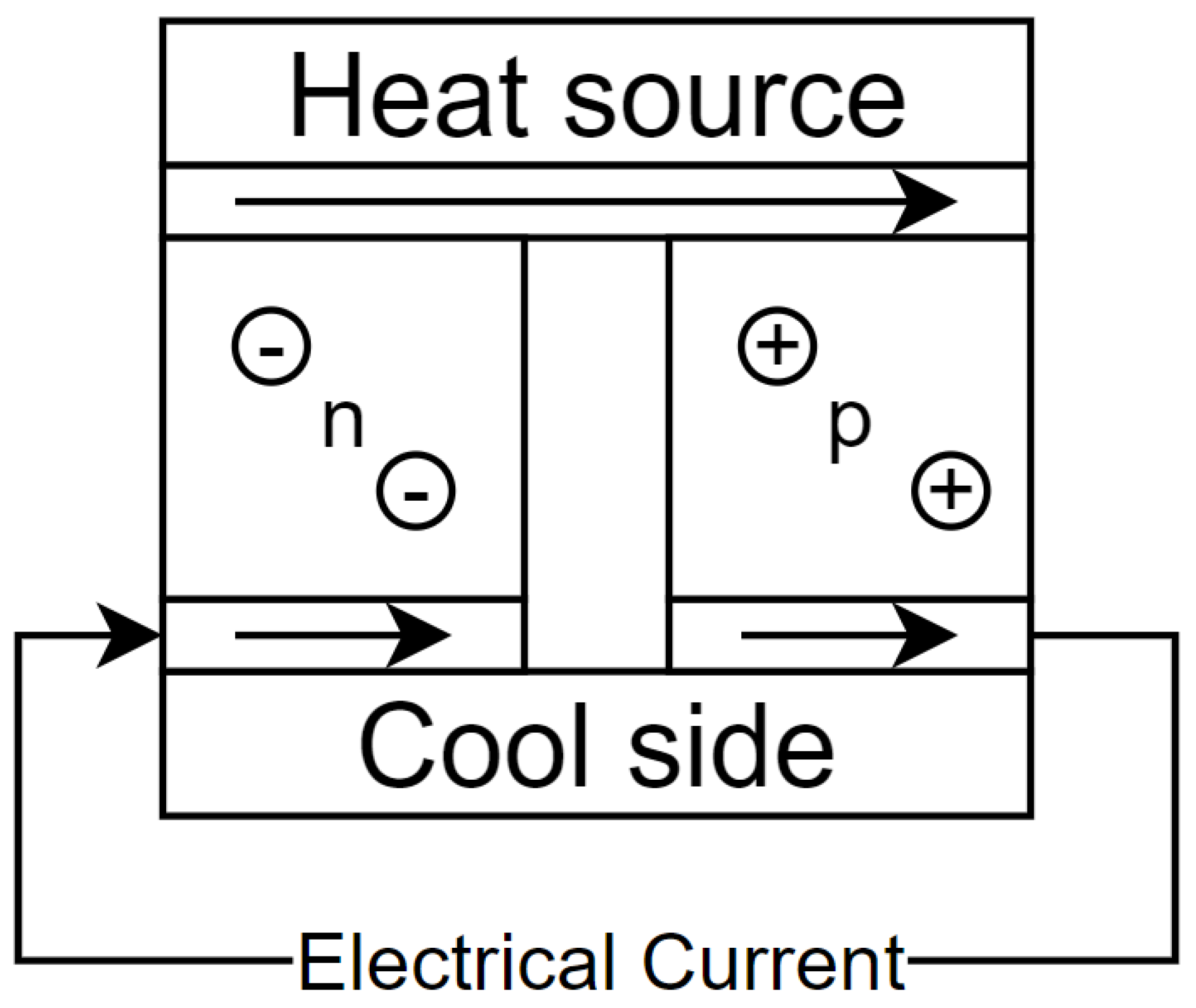
The Seebeck effect says that when we have a temperature difference between two dissimilar electrical materials (conductors or semiconductors), a voltage difference (DC) is generated between them. This voltage results from the movement of charge carriers from the hot side to the cold side, creating an electrical potential difference, as shown in Figure 6 [73].
The size of the voltage difference V D I F can be calculated based on Equation (1).
V D I F = S ( T 1 T 2 )
The T 1 is the temperature at the hot side of the thermoelectric cell.
The T 2 is the temperature at the cold side of the thermoelectric cell.
The S is the Seebeck coefficient; the value of this coefficient depends on the two materials from which the thermoelectric cell is built. Its units are volts per kelvin ( VK 1 ) or more commonly, microvolts per kelvin μ VK 1 .
Simply put, if we heat up one side of the thermoelectric cell and cool down the other side, an electrical voltage is generated between the two materials. The amplitude of the electrical voltage depends directly on the temperature difference and on the Seebeck coefficient, which is calculated based on the two materials used in the thermoelectric cell. The higher the temperature difference, or Seebeck coefficient, the higher the amplitude of the output voltage.
The Seebeck effect allows us to build sensors called thermocouplers that can measure temperature. We will apply the known temperature to one side of the thermoelectric cell and, based on the amplitude of the generated voltage, find out the temperature on the other side of the cell.
The same approach can be applied when building thermoelectric transducers. The key difference is that, in sensors, high Seebeck coefficients are not required since they only measure voltage rather than generating power for a load.
The opposite of the Seebeck effect is the Peltier effect. In the Seebeck effect, we generated electrical energy as a response to the thermal gradient between the two sides of the thermoelectric cell. In the Peltier effect, the thermal gradient between the two sides of the thermoelectric cell is generated in response to the supplied electrical energy. One common application in which the Peltier effect is used are car fridges.
Thermoelectric transducers generate a direct voltage at their output. This direct voltage must be converted to the appropriate voltage levels required by the load that the energy harvesting system is designed to power.

4.3.2. Conversion Efficiency and Power Density

The conversion efficiency of thermoelectric transducers is relatively low, typically ranging between 5% and 6%. Consequently, the generated output voltage is also minimal [69,74].
The conversion efficiency depends on the Seebeck coefficient of the two materials from which we will build the thermoelectric transducer.
In thermoelectric cells, conversion efficiency refers to the proportion of the thermal gradient that can be converted into electrical energy. The output voltage varies depending on the Seebeck coefficient, meaning different thermoelectric cells will exhibit different voltage increases based on their material properties.
The power density of a thermoelectric transducer is highly dependent on the magnitude of the thermal gradient established between its two sides. Typically, the power density of thermoelectric transducers ranges from several hundred mWm 2 to a few Wm 2 .
The thermoelectric transducer has a fast response time on the order of tens of milliseconds.

4.3.3. Types of Thermoelectric Materials

The common combinations of materials used in thermoelectric transducers are [75,76]:
  • The E-type thermoelectric transducer—The transducer is made from the Chromel (nickel-chromium alloy) and the Constantan (nickel-constantan alloy). It can handle temperatures in the range 50 °C to 740 °C. Its Seebeck coefficient is 61 μ VC 1 at 25 °C. It has high resistance to corrosion and oxidation.
  • The J-type thermoelectric transducer—The transducer is made from iron and Constantan (nickel-constantan alloy). It can handle temperatures in the range 210 °C to 750 °C. Its Seebeck coefficient is 52 μ VC 1 at 25 °C. It has good resistance to corrosion and oxidation.
  • The T-type thermoelectric transducers—The transducer is made from copper and Constantan (nickel-constantan alloy). It can handle temperatures in the range 270 °C to 370 °C. Its Seebeck coefficient is 41 μ VC 1 at 25 °C. It has good resistance to corrosion and oxidation.
  • The K-type thermoelectric transducers—The transducer is made from Chromel (nickel-chromium alloy) and Alumel (nickel-aluminum alloy). It can handle temperatures in the range 200 °C to 1260 °C. Its Seebeck coefficient is 41 μ VC 1 at 25 °C. It has good resistance to corrosion and oxidation.
  • The R-type thermoelectric transducer—The transducer is made from platinum-rhodium and platinum. It can handle temperatures in the range 50 °C to 1480 °C. Its Seebeck coefficient is 10.6 μ VC 1 at 25 °C. It has good resistance to corrosion and oxidation.
  • The B-type thermoelectric transducer—The transducer is made from platinum-rhodium and platinum. It can handle temperatures in the range 0 °C to 1700 °C. Its Seebeck coefficient is 10.5 μ VC 1 at 25 °C. It has high resistance to corrosion and oxidation.
However, the Seebeck coefficients are usually non-linear and vary with the amplitude of the temperature gradient. The generated voltage is not linearly dependent on the temperature gradient.

4.3.4. Applications of Thermoelectric Transducers

In the form of actuators, thermoelectric transducers are used to either decrease or increase the temperature inside an object. This is achieved by connecting the thermoelectric transducer to a source of electrical energy, utilizing the Peltier effect. A common application of these actuators is in car fridges. These fridges operate by having the thermoelectric transducer siphon heat from inside the fridge and transfer it to the external environment, thereby cooling the interior [74].
Thermoelectric transducers are often used in the form of sensors called thermocouplers to measure temperature.
Thermoelectric transducers are used in power generation to convert waste heat into electricity, in spacecraft to harness heat from radioactive decay, and in cooling systems. Waste heat can take various forms; common examples include heat produced by the operation of machines such as large engines or the heat generated by steam pipes in power plants [77,78].
One application in which thermoelectric transducers can achieve high electrical voltage generation is Concentrated Solar Thermal Cells (CSV). These technologies operate similarly to the CPV technology mentioned in the chapter on photovoltaic cells. The primary difference is that the photovoltaic cell is replaced with a thermoelectric transducer. A mirror concentrates the sun’s energy onto a single point where the transducer is located. This leads to the heating of the thermoelectric transducer and the generation of electrical energy [79].
Another application involves utilizing residual heat energy during energy generation in conventional power plants (fossil fuel or nuclear). In these plants, heated steam must be cooled back into water, a process typically carried out in cooling towers using air or water cooling. During this process, pipes carrying hot steam pass through a cooling medium, such as a tank with cold water or air, where residual heat energy is dissipated. However, these pipes can be covered with thermoelectric transducers as they travel from the turbine to the cooling tower. These thermoelectric transducers can generate additional electrical energy by capturing the heat dissipated from the pipes, which would otherwise be wasted [80].
An application in the field of transportation involves harvesting thermoelectric energy from the thermal gradient between sun-heated asphalt and the soil at a certain depth. In this application, the soil acts as a passive cooler [81,82].
In both the sensors and power generation, we are using the Seebeck effect.

4.3.5. Advantages of Thermoelectric Transducer

Thermoelectric transducers are valued for their reliability, low maintenance, low cost, durability in harsh conditions, simple construction and compact size, making them suitable for various applications [67,68].
The main advantage of thermoelectric transducers is that they can be used in a wide range of temperatures, from 270 °C to 2800 °C. Thanks to this wide range, they are capable of generating a high amount of energy in applications where the temperature gradient remains constant and sufficiently high.
Another advantage is their fast response time, allowing them to react well to rapid changes in temperature on either side of the thermoelectric transducer. Unfortunately, this responsiveness is also one of their disadvantages.

4.3.6. Disadvantages of Thermoelectric Transducer

The challenge with thermoelectric transducers lies in maintaining a constant temperature gradient between the two sides to generate continuous energy. To achieve this, we need to use coolers to decrease the temperature on the cold side. Otherwise, the cold side will heat up due to the hot side, resulting in a small temperature gradient and reduced energy generation [68,69,70].
This is not a problem if the required temperature gradient is not high; in that case, we can use passive coolers that do not require any energy to operate. However, if the required temperature gradient is high, we need to use active coolers that require energy for their operation. Unfortunately, due to the small conversion efficiency, we may find ourselves in a situation where the amount of energy generated by the thermoelectric transducer is lower than the amount of energy required by the active cooler.
The next disadvantage of thermoelectric transducers is that certain types are vulnerable to corrosion.
Lastly, the changes in the output voltage have a nonlinear relationship to the changes in the thermal gradient. This is caused by the nonlinear relationship between the Seebeck coefficient and the thermal gradient.

4.3.7. Current Research Goals

Research in the field of thermoelectric transducers is currently focused on finding new thermoelectric materials, improving the low conversion efficiency of thermoelectric cells, reducing costs, and making them more suitable for a wider range of applications [76,83,84,85]
Since 2023, researchers have been capable of creating thermoelectric transducers with conversion efficiency reaching 15.2%. However, these transducers have so far only been tested in laboratories, and they are not available to customers yet [86].
The problem with ordinary thermoelectric transducers is that the two materials from which the transducer is made are created separately, and they need to be joined together either by brazing or soldering. However, this creates a heterogeneous interface between these two materials, which reduces the thermoelectric transducer conversion efficiency.
This new approach eliminates the need to join the materials. Thus, we do not have any heterogeneous interface between them. Instead of that, both sides of the thermoelectric transducer are created together in a single step.

4.4. Triboelectric Transducer

4.4.1. Working Principle of Triboelectric Transducer

A triboelectric transducer utilizes the triboelectric effect to convert mechanical energy into electrical energy [87,88,89].
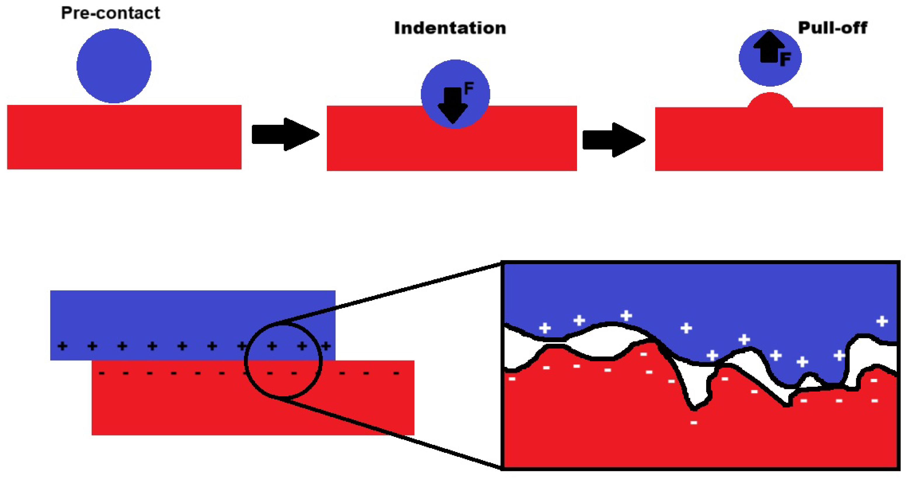
This effect occurs when two different materials come into contact and then separate, leading to the transfer of electrons. This contact is achieved as a result of external mechanical energy.
The transfer of electrons is caused by the material’s varying tendencies to attract or release electrons from its structure. One material becomes positively charged, while the other becomes negatively charged.
This contact between different materials can occur in two basic modes, which are shown in Figure 7.
The first mode is called the vertical contact-separation mode. During this mode, one of the materials makes vertical contact with the other materials, and then they separate. This mode can be used to collect mechanical energy from vibrations. In transducers implementing this mode, one of the materials is fixed, and the other materials moving up and down on top of the fixed materials as the result of the vibration, thus creating the contact-separation movement.
The second mode is called contact sliding mode. During this mode, one of the materials slides on top of the other. Because the materials are not completely flat, as we can see from the picture, the contact-separation movement also occurs during this process. This mode can be used to collect mechanical energy from movement. In transducers implementing this mode, one of the materials is fixed and the other material is sliding on top of the fixed materials as a result of the movement of the object to which it is connected.
An example of a triboelectric effect that occurs in everyday life is the contact of human skin with polyester clothing, during which an electrical spark is generated.
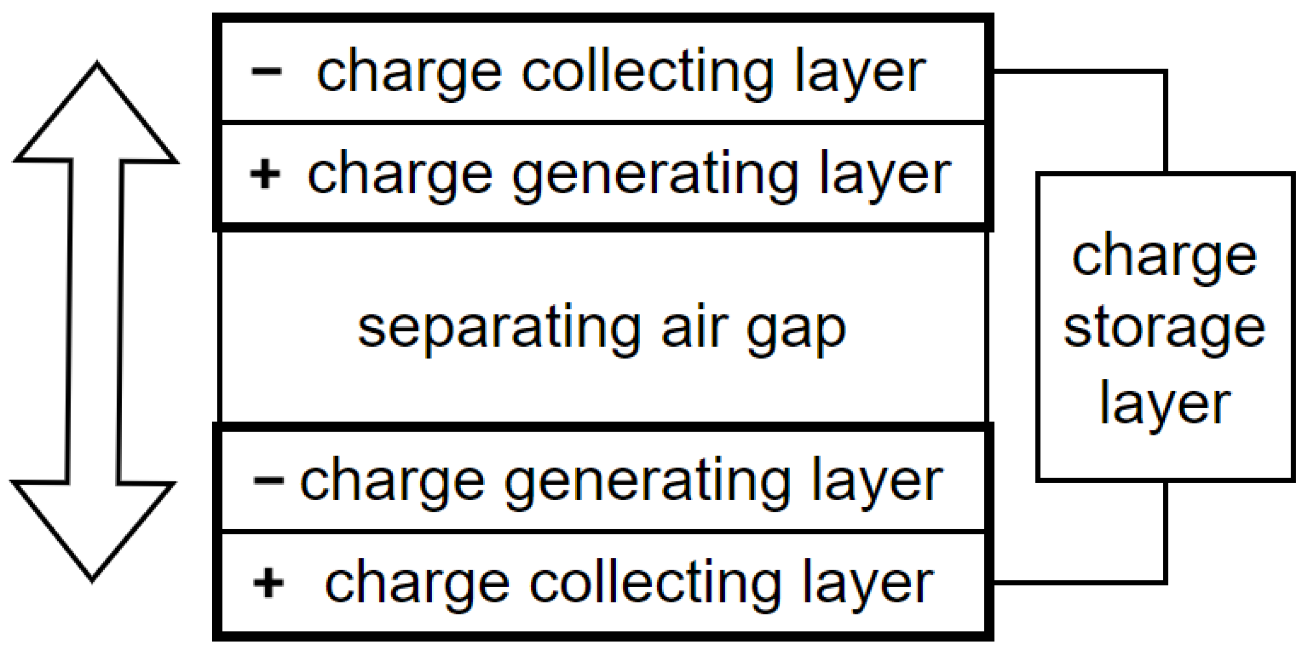
The two dissimilar materials are usually layered between conductive materials (electrodes), forming a pathway for the generated electrical charge (current) to be collected and directed to an external circuit, as shown in Figure 8.
Triboelectric transducers are particularly useful in applications where mechanical motion is abundant.
Triboelectric transducers generate an alternating voltage at their output. This voltage must be rectified to convert it into direct voltage. The direct voltage then needs to be adjusted to the appropriate voltage levels required by the load that the energy harvesting system is designed to power.

4.4.2. Conversion Efficiency and Power Density

The conversion efficiency of triboelectric transducers depends on the choice of materials and their surface characteristics, which are partially influenced by temperature and humidity, as well as the dynamics of contact and separation or sliding movement [89].
The most commonly used type of triboelectric transducers nowadays is the Triboelectric Nanogenerators (TENGs), whose conversion efficiency, in a commerical context, ranges from 70% to 85%.
The power density of triboelectric nanogenerators depends on their application and the construction of the nanogenerators. In some studies, they were capable of generating outputs with a power density of 11.13 kWm 2 . In others, the power densities were just around 100 Wm 2 [91].
However, the sizes of these nanogenerators are really small, and these values are usually calculated based on the output power density of a small triboelectric nanogenerator.
Furthermore, during a lot of these studies, the experiments were undertaken in laboratory conditions and not in real-world conditions.
The triboelectric transducer has a fast response time on the order of milliseconds or hundreds of microseconds.

4.4.3. Types of Triboelectric Materials

Unlike the thermoelectric transducers, where we could use just certain materials to achieve the Seebeck effect, the triboelectric effect can occur between any two dissimilar materials [92,93].
However, the size of the electrical charge that will be generated is dependent on the two materials used.
For the majority of the materials, the generated electrical charge is too small. Because of this, in triboelectric transducers, just certain materials, often called triboelectric materials, are used.
The most commonly used type of triboelectric transducer today is the TENGs. The materials used in these generators vary depending on the specific application [91,94].
Innovations in materials and design are enhancing the triboelectric effect, thereby improving energy conversion efficiency and allowing the triboelectric transducers to be used in new applications.

4.4.4. Applications of Triboelectric Transducers

The triboelectric transducers can be used in many areas, ranging from powering wearable electronics through self-powered sensors to acting as sensors for human–machine interfaces such as touchpads or electrical skin that require sensing mechanical interactions, which is possible thanks to the triboelectric effect.
TENGs are miniature generators that use the triboelectric effect to generate a small amount of electrical energy. These TENGs are capable of generating energy in various applications [92,95,96,97,98].
These TENGs are made from nanomaterials, which are materials that typically have a size of less than 100 nm.
There are four main areas in which this TENGs can be used:
  • Wearable textiles—Textile Triboelectric Nanogenerators (tTENGs) are sewn into the fabric from which clothes are made. During human motion, these tTENGs generate a small amount of energy, which can be used, for example, to partially recharge small electronic devices [99,100].
    The first tTENG used in wearable textiles was created in 2014. This Woven-structured TENG (W-TENG) was constructed using two triboelectric materials, nylon and polyester, with Ag fabric serving as the conductive material. When the W-TENG is subjected to stretching or compression due to human movement, electrical energy is generated.
    Since this year, more efficient and complicated tTENGs have been designed. The triboelectric materials used in the wearable textile need to be flexible, comfortable during wear, and durable. Because of that, materials such as polytetrafluoroethylene, polydimethylsiloxane, polyethylene cotton, and silk are often used.
  • Water wave energy—which falls under the category of so-called blue energy—is energy generated from water bodies. In this context, TENGs are used to harvest energy from waves in oceans or rivers. These waves are driven by the gravitational forces of the Sun and Moon acting on the Earth [101,102,103].
    TENGs are placed inside marine buoys, and the movement of the waves causes the buoys to move as well. Consequently, TENGs generate energy from this motion. This energy could power various marine devices, including smart buoys, night lights, floating weather stations, and maritime surveillance equipment.
    The triboelectric materials used need to have good durability against corrosion caused by salty water. Because of that, the combinations polytetrafluoroethylene and aluminium, polydimethylsiloxane and copper, and polyethylene and graphite are often used.
  • Wind energy harvesting—electromagnetic generators, typically in the form of wind turbines, are commonly used to convert the kinetic energy of the wind into electricity, they struggle to generate energy from low-speed winds [104,105,106].
    This is where TENGs excel, offering high efficiency even in low-speed wind conditions. Incorporating TENG devices into existing wind turbine farms could increase their overall energy production.
    The triboelectric materials used need to be durable and capable of withstanding extreme outdoor conditions. Because of that, materials such as polytetrafluoroethylene, polydimethylsiloxane, polyethylene aluminium, and graphite are often used.
  • Transportation. In this area, there are two major applications for TENGs.
    The first application is the collection of wind energy caused by the movement of vehicles.
    The second application is the collection of energy from the contact between the tires and the road surface. The TENGs are placed on car tires, and thanks to the friction against the road, they can generate electrical energy. TENGs have already been experimentally used in Advanced Driving Assistance Systems (ADAS), where they power sensors that monitor tire conditions such as pressure, road contact, and tire direction [107,108,109].
    The triboelectric materials used need to be durable against the mechanical stress to which they are exposed in these applications. Because of that, materials such as polytetrafluoroethylene, polydimethylsiloxane, polyethylene aluminium, and graphite are often used.

4.4.5. Advantages of the Triboelectric Transducers

Both the natural and the industrial mechanical movements are abundant in our world.
The currently commercially used TENGs are built from low-cost materials, and the production processes are easy, which is reducing the cost of this energy-harvesting system.
The main advantage of the commercially used TENGs is their high conversion efficiency.

4.4.6. Disadvantages of the Triboelectric Transducers

There are multiple problems that are preventing the widespread use of TENGs in certain applications:
  • Durability—only a limited number of tests have been conducted with specific TENGs outside of laboratory conditions. As a result, it remains uncertain how well they will endure extreme environmental conditions, such as high or low temperatures, corrosion caused by salty water in wave energy applications, or repeated machine washing of wearable textiles. Due to these environmental factors, materials with the best triboelectric properties for a given application cannot always be used. Instead, a compromise between the device’s durability and its energy generation efficiency must be made [110,111].
  • Wear—TENGs generate energy through friction between two different materials, leading to wear. As a result, the lifespan of TENGs that use nanomaterials can be short if the problem with friction is not properly solved [112].
  • Manufacturing processes—so far, certain TENGs have been produced in small series for testing purposes. However, if they were to be used on a commercial scale, a considerable investment in the necessary technology would be required. Additionally, due to constant technological improvements, this technology could quickly become obsolete and need upgrading. Another issue related to manufacturing and electrical output is that many modern TENGs are made from complex materials that require multiple processing steps. Consequently, the cost efficiency of some TENGs solutions may be low [95].
  • Electrical output—despite significant progress in conversion efficiency since their inception, TENGs still suffer from low electrical output. This problem is magnified by the fact that they are generating on their output Alternating Current (AC), which needs to be rectified to be used by the final device. During this rectification process, another voltage loss occurs, which further decreases their energy production. This limitation is particularly pronounced for TENGs used in wearable textiles, where the generated energy reaches a maximum of 9 Wm 2 , which is more than 50 times less than more conventional non-textile TENGs, which are capable of generating up to 500 Wm 2 [113,114,115].
  • The amount of power generated by some of the TENGs in real-world conditions is not yet well known, since a big part of the test was performed under laboratory conditions.

4.4.7. Current Research Goals

Ongoing research aims to address the challenges of TENGs in specific applications and explore new areas where TENGs could be utilized.
TENGs represent a highly promising area of energy harvesting that could significantly contribute to meeting the ever-growing energy demands of our civilization in the future.
However, extensive research is still required before triboelectric transducers can be deployed on a large scale in certain applications.

4.5. Electromagnetic Transducer

4.5.1. Working Principle of Electromagnetic Transducer

An electromagnetic transducer implementation is based on the principles of electromagnetic induction. The transducer is capable of converting mechanical energy into electrical energy and vice versa, following Faraday’s law of electromagnetic induction [116,117,118,119,120,121,122].
This law states that a voltage is induced in a conductor when it experiences a change in the magnetic field around it. This effect is typically achieved by either moving a conductor through a magnetic field or by changing the magnetic field around a stationary conductor.
In practical applications, this phenomenon is often observed in generators, where rotating a coil (conductor) within a magnetic field generates electrical energy from mechanical motion. Conversely, when an electrical current is applied to a coil in a magnetic field, it creates a mechanical force, enabling the transducer to function as an actuator, as seen in electric motors.
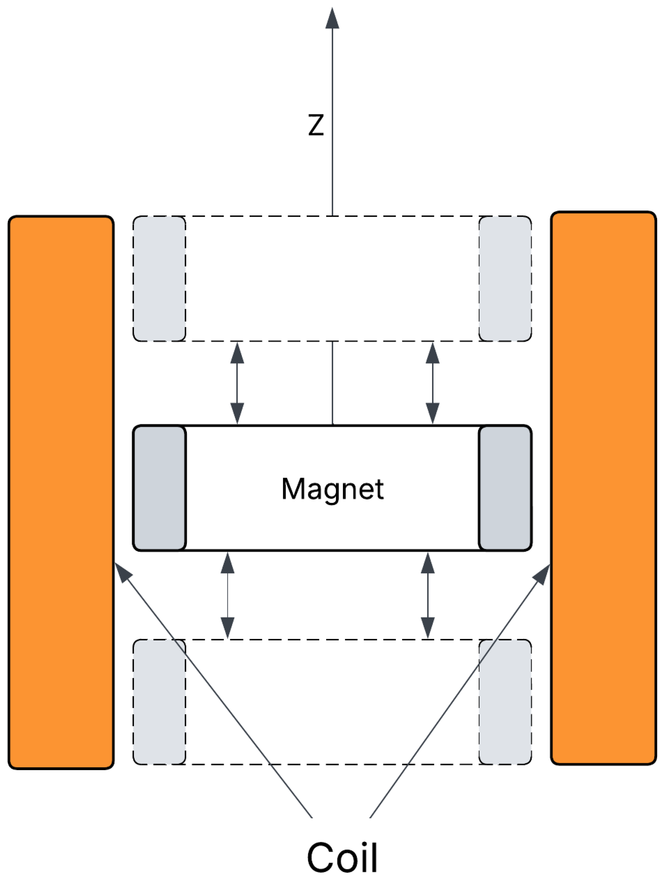
Figure 9 shows the working principle of the electromagnetic transducer. In this figure, the coil position is static and the permanent magnet, which generates the magnetic field, is moving up and down. As a result, the coil is exposed to changes in the magnetic field generated by the permanent magnet, which leads to the generation of electrical energy in the coil.
When we connect this coil to the external circuit, the generated electrical energy can be directly used or stored for later use.
Electromagnetic transducers generate an alternating voltage at their output. This voltage must be rectified to convert it into direct voltage. The direct voltage then needs to be adjusted to the appropriate voltage levels required by the load that the energy harvesting system is designed to power.

4.5.2. Conversion Efficiency and Power Density

Their efficiency depends on factors such as magnetic field strength, which in turn depends on the ferromagnetic material used as the permanent magnet, the coil design, the ferromagnetic material used in the core of the coil, the type of conductor woven around the core of the coil, and the speed of change in the magnetic field [124,125].
The power density of electromagnetic transducers also depends on the properties of the materials used, on the overall design of the transducer and the type of mechanical stress that is applied to them. The power density can move a few hundred μ Wm 2 to a few tens of Wm 2 .
The electromagnetic transducer has a fast response time on the order of milliseconds or hundreds of microseconds.

4.5.3. Materials Inside of Electromagnetic Transducers

Inside the electromagnetic transducers, there are two main components: the permanent magnet that generates the electromagnetic field and the coil, which acts as the conductor [120,126,127,128,129].
The permanent magnets are made from hard ferromagnetic materials.
The strength of the magnetic field generated by the magnets is given in the units of tesla.
The coercivity is the measure of the resistance of a magnetic material to demagnetization under external influence, such as external magnetic fields or temperature change. The higher the coercivity, the higher the resistance.
There are four commonly used ferromagnetic materials nowadays. All of these materials are brittle, which means that when they are exposed to bigger mechanical pressure, they can fracture cleanly.
  • Ferrite—It is made from iron oxide and other metallic elements. It has high corrosion resistance, and it can operate even in temperatures reaching 250 °C. Ferrite is used in many applications thanks to its low cost, since its main component is cheap iron. It is capable of generating magnetic fields ranging from 0.1 to 0.5 T (Tesla). Its coercivity is between 100 and 300 kAm 1 . Its magnetic strength decreases by approximately −0.2% per °C above ambient temperature ( 25 °C).
  • Alnico—It is an alloy of aluminium, nickel, and cobalt. It has a high corrosion resistance, and it can operate even in high temperatures, reaching 550 °C. It has good temperature stability. It is capable of generating a magnetic field of 0.15 T. Its coercivity is between 50 and 150 kAm 1 . Its magnetic strength decreases by approximately −0.02% per °C above ambient temperature ( 25 °C).
  • Neodymium-iron-boron (NdFeB)—It is made from rare earth elements. It is capable of generating a magnetic field ranging from 1 to 1.3 tesla. It can be used up to 230 °C. Its coercivity is between 750 and 2000 kAm 1 . Its magnetic strength decreases by approximately −0.12% per °C above ambient temperature ( 25 °C).
  • Samarium-cobalt (SmCo)—It is made from rare earth elements. It has high corrosion resistance, and it can operate even at high temperatures reaching 300 °C without a significant decrease in its magnetic field. It is capable of generating a magnetic field ranging from 0.8 to 1.16 tesla. Its coercivity is between 600 and 2400 kAm 1 . Its magnetic strength decreases by approximately −0.04% per °C above ambient temperature ( 25 °C).
The coils are made from materials that can conduct electrical energy; nowadays, the majority of the coils are made from aluminium or copper wires, which have good electrical conductivity properties and low cost.
To increase the electromotive force of the coil, the copper or aluminium is usually wound around a core composed of ferromagnetic materials such as nickel alloys, cobalt, or iron.

4.5.4. Applications of Electromagnetic Transducers

Electromagnetic transducers find widespread use across various applications, from generating electricity in wind turbines and hydroelectric plants to powering motors in appliances and vehicles.
Wind turbines that use electromagnetic transducers typically have a conversion efficiency ranging from 30% to 50% when the wind speed is between 48 and 80 kmh 1 [130,131,132,133,134].
However, these wind turbines usually automatically shut down if the wind speed exceeds 88.5 kmh 1 . Additionally, they cannot generate energy when the wind speed is too low.
As an example, a good residential wind turbine should be capable of generating 2 to 10 kW of energy. Under the right conditions, it can produce 3 to 15 MWh of energy per year.
One advantage of wind turbines is that they require only a small area on the ground because their blades, which are the largest part of the wind turbine, are up in the air.
While the initial cost of wind turbines can be quite high, their operating costs are low. Thanks to this, they are capable of paying for themselves in approximately 6 to 8 years, depending on the conditions in the area where they are placed. The lifespan of modern wind turbines is approximately 20 years.
The disadvantage of wind turbines is that they cannot be placed in areas with low wind speeds. Wind turbine farms are often located in remote areas without obstacles that would reduce wind speed. Consequently, it is often necessary to build transmission lines and other infrastructure from the wind turbine farm to the location where the generated energy is used.
The other disadvantage of wind turbines is that they create visual pollution due to their height. While this is less problematic in remote areas, it becomes an issue in locations near cities, where people often oppose their construction.
Hydroelectric plants also utilize electromagnetic transducers; they have a conversion efficiency between 80% and 90% [135,136,137,138,139].
For instance, a small-scale hydroelectric plant can generate up to 10 MW of energy, and under the right conditions, it should be capable of producing 50 TWh of energy per year. The largest hydroelectric plant, the Three Gorges, located in China, can produce a staggering 540 TWh of power each day.
The advantages of hydroelectric plants include their fast response time, long lifespan (usually between 50 and 100 years), and minimal operation and maintenance costs.
However, there are also disadvantages. The primary one is the initial cost, which typically falls within the range of hundreds of millions of dollars. Additionally, hydroelectric plants have a lengthy construction timeline, spanning multiple years.
The other problem associated with building a hydroelectric plant is the need for a massive reservoir of water, which requires tens or even hundreds of square miles of land. This reservoir has implications for the local ecosystem, both within the reservoir area and downstream. Additionally, it necessitates the relocation of people who previously lived in the area where the reservoir was built.
However, this reservoir also offers advantages. It can protect communities from high waters and flooding during rainy seasons by controlling the water level in the rivers on which the hydroelectric plant is built. Furthermore, it creates opportunities for farmland around the reservoir, thanks to a consistent water supply, even during droughts.
The reservoirs are nowadays also used for the generation of energy through the floating photovoltaic panels, this approach further increases the power output of the hydroelectric plant [140].
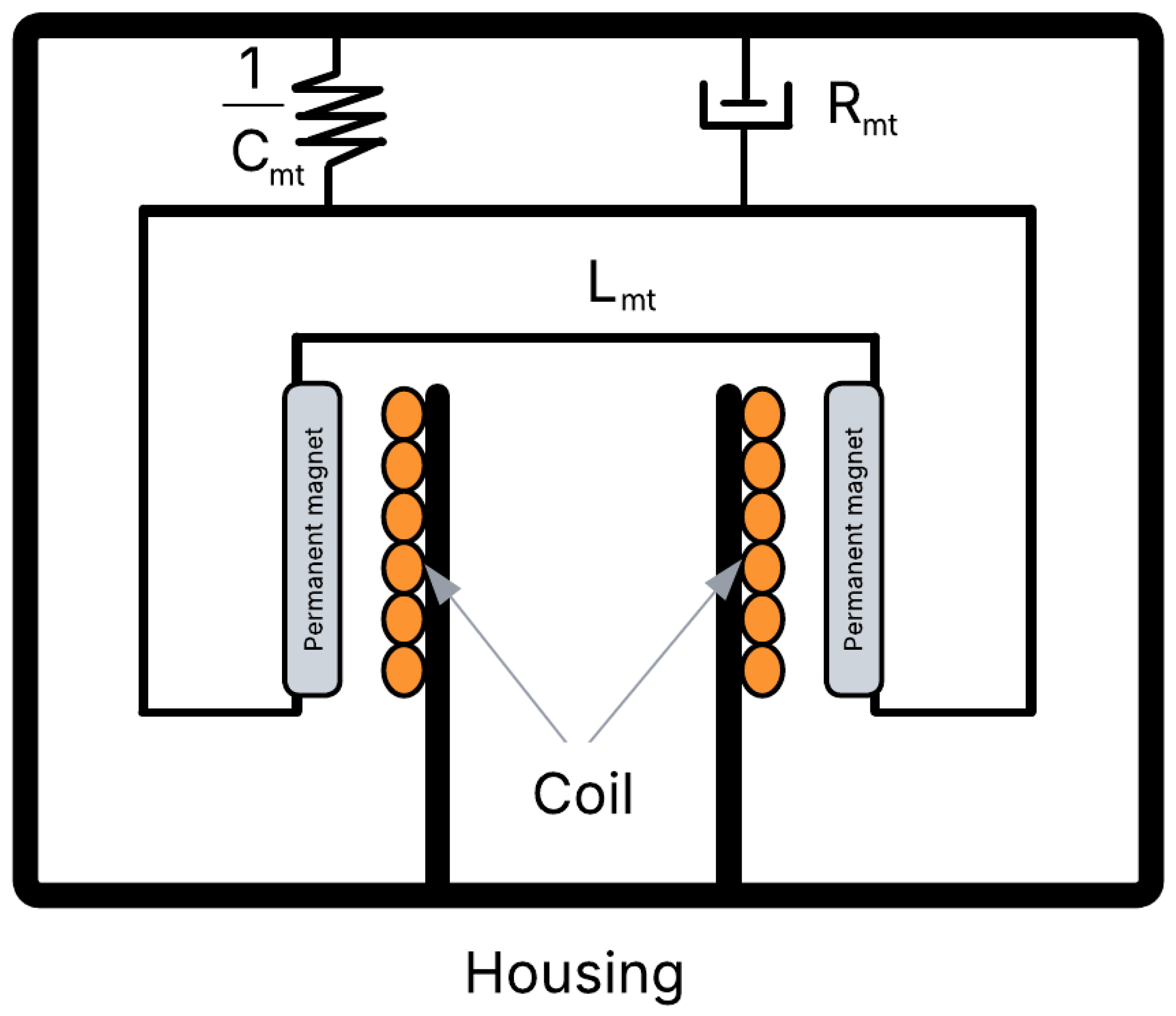
Electromagnetic transducers can also be used to harvest vibrational energy. The basic construction principle of these electromagnetic transducers is shown in Figure 10 [141,142].
The coil has a fixed position, and the permanent magnets are connected to a mass–spring–damper system. As a result of vibrations, the permanent magnets start to move up and down, resulting in a change in the magnetic field around the coil. As a result, electrical energy will be generated inside of the coil.

4.5.5. Advantages of the Electromagnetic Transducers

The electromagnetic transducers have a high conversion efficiency.
They are capable of operating in a wide range of frequencies. The frequency depends on the change in the magnetic field affecting the coil. This makes them usable in both small-frequency applications such as vibrational energy harvesting and high-frequency applications such as hydroelectric plants.
The electromagnetic transducers are robust and durable against environmental damage. They can be operated in environments with a wide range of temperatures. They are also capable of resisting mechanical stress applied to them without getting damaged.
The electromagnetic transducers are easily scalable; they can be made in different sizes based on the specific application needs [116,117,118,119,120,121].

4.5.6. Disadvantages of the Electromagnetic Transducers

The design and production of electromagnetic transducers is a more complicated process compared to other types of energy harvesting systems.
The electromagnetic transducers are built from two types of materials. The permanent magnets and the core of the coil are built from ferromagnetic materials. The conductors are woven around the ferromagnetic core in the coil. Both of these materials are heavy. And if we want to make a bigger electromagnetic transducer, such as the one used in hydroelectric power plants or big wind turbines, the size and weight of such a transducer will be quite high.
These first two disadvantages lead to the third, and that is the increase in the cost of this type of energy harvesting system when used on a large scale. This increase is caused by the more complicated design of the transducers in order to achieve high efficiency in the specific large-scale application in which they will be used and by the price of the ferromagnetic materials and conductors used in these ferromagnetic transducers.
Two of the advantages of electromagnetic transducers were their ability to operate at a wide range of frequencies and with high conversion efficiency. However, in low-frequency applications, their conversion efficiency usually decreases.
The electromagnetic transducers used in hydroelectric plants or in wind turbines contain moving parts in the internal mechanical system that capture the kinetic energy in the water and wind movement and transform it into the movement of the permanent magnets in the electromagnetic generators. However, the moving parts inside of these transducers are exposed to mechanical forces, which leads to their wear over a certain period of time and the need for their replacement.
The electromagnetic transducers are based on the principle of electromagnetic induction, where the conductor is exposed to changes in the magnetic field, and as a result, electrical energy is generated inside of it. However, what if, in the environment where these transducers are placed, there are other sources of magnetic fields? These other sources will create magnetic interference, which can affect the working and the conversion efficiency of the electromagnetic transducers. In these applications, the electromagnetic transducers need to have magnetic shielding that will not allow these magnetic interferences to penetrate the cover of the electromagnetic transducer and thus affect its operation. This shielding will, however, increase the price of the electromagnetic transducer [116,117,118,119,120,121].

4.5.7. Current Research Goals

Research in the field of hydroelectric plants focuses on increasing conversion efficiency and developing ecologically improved turbines and hydropower converters that are less likely to harm the fish and other animals living in the reservoir [136,137].
Research in the field of wind turbines focuses on increasing the conversion efficiency, particularly for small and medium-sized wind turbines. Additionally, efforts are underway to establish offshore wind turbine farms in ocean locations where wind speeds remain consistently high throughout the year and where visual pollution is minimized [131,133].
Scientists are trying to increase the energy efficiency of electromagnetic transducers when used in applications where the frequency of the change in the electromagnetic field is low or has a constant value [144,145,146,147].
Another area where research is being conducted is miniaturization. The development of smaller and lighter electromagnetic transducers that could be used in new applications would lead to an increase in global energy production from electromagnetic transducers [148,149,150].
Research in the area of ferromagnetic materials and conductors helps improve the conversion efficiency and durability and reduce the cost of the electromagnetic transducers.
Continuous technological improvements lead to the enhanced performance of electromagnetic transducers and make them more efficient in the applications in which they are used.

5. Energy Storage

Energy storage refers to the process of capturing energy in a form that can be retained and subsequently released to supply power or perform work at a later time.
Important characteristics, capabilities, and parameters common to most energy storage systems include:
  • Energy density—refers to the amount of energy stored per unit of volume or weight. Higher energy density means that the same amount of energy can be stored in smaller systems.
  • Power density measures the rate at which energy can be delivered by the storage system. Higher power density means that the system can give quick bursts of energy and thus supply bigger currents to the rest of the system.
  • Efficiency is the ratio of the energy output to the energy input of the system. Higher efficiency means less energy is lost in the energy storage process.
  • Cycle stability refers to how well the system maintains its efficiency and capacity over many charge and discharge cycles.
  • Charge rate determines how fast the energy storage can be fully charged from a fully discharged state by an energy source with certain parameters.
  • Discharge rate determines how fast the energy storage can be fully discharged from a fully charged state by the load with a certain power consumption.
  • Response time refers to the speed at which the storage system can respond to energy demand changes.
  • Environmental impact refers to the materials used in the energy storage system both from the point of view of the environmental impact caused during the mining and processing of the materials and the environmental impact if the energy storage system is not properly disposed of.
  • Safety is a very important parameter when it comes to energy storage. Different types of energy storage have different conditions under which they become unsafe. For example, if we throw rechargeable batteries into the fire, they will explode. Therefore, in each application in which there is a possible fire hazard, we must make sure the batteries will not get exposed to the flames. Therefore, if we use rechargeable batteries in electric cars, we must put them into a fireproof box that will prevent their explosion in the case that the car will catch fire.
These types of storage can have various forms, as shown in Figure 11—chemical, electrical, mechanical, or thermal, and each method has its unique mechanisms and applications [151].
In the following sections, we will shortly explore the most common energy storage implementations.

5.1. Mechanical Storage

Mechanical energy storage technologies involve storing energy in a physical form and later converting this energy back into a usable form, typically electricity. The most commonly used implementations of mechanical energy storage are discussed as follows.

5.1.1. Pumped Hydroelectric Storage (PHS)

Pumped hydro storage is the most common form of mechanical energy storage. It operates by pumping water from a lower-elevation reservoir to a higher-elevation reservoir during periods of low energy demand or excess energy generation. This process effectively stores energy in the form of gravitational potential energy. When electricity demand increases, the stored water is released back down through turbines, converting the potential energy into kinetic energy, which in turn drives generators to produce electricity.
This method of energy storage is widely used due to its high efficiency, typically ranging from 70% to 80%, and its ability to provide large-scale energy storage capacity. Pumped hydro storage plays a crucial role in balancing the grid by accommodating fluctuations in energy supply and demand, particularly in renewable energy systems, where generation from sources like wind and solar is intermittent.
Additionally, pumped hydro storage offers long-duration energy storage capabilities, allowing it to supply power for extended periods when renewable energy production is low. Despite its many advantages, the implementation of pumped hydro storage is often constrained by geographical limitations, as it requires suitable terrain with access to water reservoirs and significant initial capital investment for infrastructure development. However, ongoing research and advancements in closed-loop pumped hydro systems and underground reservoirs are expanding its feasibility in a wider range of locations [152].

5.1.2. Compressed Air Energy Storage (CAES)

Compressed air energy storage (CAES) stores energy by using electricity to compress air and store it in an underground reservoir, such as a salt cavern, depleted gas field, or specially designed storage tanks. During periods of low electricity demand or excess energy production, air is compressed and injected into the storage reservoir, effectively converting electrical energy into potential energy.
When energy is required, the stored compressed air is released, heated, and expanded through a turbine to generate electricity. In traditional CAES systems, the air is heated using natural gas before expansion to improve efficiency, whereas advanced adiabatic CAES systems aim to capture and reuse the heat generated during compression, reducing the need for external fuel sources and improving overall efficiency.
CAES provides a reliable and scalable energy storage solution with long-duration discharge capabilities, making it suitable for balancing intermittent renewable energy sources such as wind and solar. However, its implementation depends on suitable geological formations for air storage and the efficiency of thermal management strategies. Ongoing research aims to improve the round-trip efficiency and environmental impact of CAES, enhancing its role in the transition to a more sustainable energy grid [153].

5.1.3. Flywheel Energy Storage (FES)

Flywheel energy storage stores energy kinetically in a rotating mass. Electrical energy is converted into kinetic energy by using a motor to accelerate a rotor to very high speeds, typically within a vacuum-sealed enclosure to minimize air resistance and friction. The rotor continues spinning due to its inertia, effectively storing energy in the form of rotational motion.
When energy is needed, the stored kinetic energy is harnessed by slowing down the rotor, allowing its rotational inertia to drive a generator, which converts the kinetic energy back into electricity. Flywheel energy storage systems offer several advantages, including rapid charge and discharge times, high power density, and long cycle life with minimal degradation over time. Unlike chemical batteries, flywheels do not suffer from capacity loss due to repeated charge–discharge cycles.
Flywheels are particularly useful for applications requiring short-duration, high-power bursts, such as grid stabilization, frequency regulation, and uninterruptible power supplies (UPS). However, their energy storage capacity is limited compared to other storage technologies, making them less suitable for long-term energy storage. Ongoing advancements in materials and magnetic levitation technology continue to improve the efficiency and performance of flywheel energy storage systems, expanding their potential applications in modern energy grids and transportation systems [154].

5.1.4. Gravitational Energy Storage

Gravity energy storage involves elevating a mass using surplus energy and then releasing this mass to generate electricity when needed. During periods of excess energy production, electrical energy is used to lift heavy weights, such as concrete blocks or large metal masses, to a higher elevation, storing energy in the form of gravitational potential energy.
When energy demand increases, the stored mass is lowered, and the gravitational force acting on it drives a generator to produce electricity. This system operates similarly to pumped hydro storage but without the need for water reservoirs, making it a viable alternative in regions where hydro-based storage is not feasible.
Gravity-based energy storage systems offer advantages such as long-duration storage, minimal energy loss over time, and the ability to scale based on available space and load capacity. They also have a long operational lifespan with minimal environmental impact. However, their efficiency depends on factors such as mechanical losses, lifting mechanisms, and the availability of suitable infrastructure.
Ongoing research and development efforts are focused on optimizing gravity energy storage designs, including underground and high-rise tower systems, to improve efficiency and expand their potential applications in renewable energy integration and grid stabilization [155].

5.2. Electrochemical Storage

Electrochemical energy storage refers to a method of storing energy through chemical reactions within an electrochemical cell. This type of storage is most commonly associated with batteries, where energy is stored in the form of chemical energy and converted into electrical energy when needed. The most commonly used types of batteries nowadays are lead-acid batteries, lithium-ion batteries, sodium-sulfur batteries, Zn-air batteries, flow batteries, and supercapacitors [156].

5.3. Thermal Storage

Thermal Energy Storage (TES) technology is a method of storing thermal energy by heating or cooling a storage medium so that the stored energy can be utilized later for heating and cooling applications, as well as power generation. TES systems operate by capturing excess thermal energy during periods of low demand or surplus energy production and releasing it when needed, improving energy efficiency and grid reliability.
Different storage media can be used in TES systems, including water, molten salts, phase-change materials (PCMs), and solid-state materials such as rocks or ceramics. The stored thermal energy can be used directly for space heating and cooling, industrial processes, or converted back into electricity in power plants.
TES technologies are classified into three main types: sensible heat storage, which relies on temperature changes in a material; latent heat storage, which uses phase-change materials to absorb and release heat at a constant temperature; and thermochemical storage, which leverages reversible chemical reactions to store and release energy efficiently.
TES plays a crucial role in enhancing the efficiency of renewable energy sources, such as concentrated solar power (CSP) plants, by storing excess heat for later electricity generation. It also supports energy conservation in buildings and industrial sectors by optimizing heating and cooling systems. Ongoing research focuses on improving storage efficiency, material durability, and integration with smart energy management systems to further expand the applicability of TES in modern energy grids [157].

Thermochemical Storage

Thermochemical energy storage involves chemical reactions that store and release thermal energy. These reactions absorb heat energy during the charging phase, which can later be released through a reverse reaction when energy is needed. This process allows for highly efficient and long-duration energy storage, as thermal energy can be retained with minimal losses over extended periods.
Thermochemical storage systems typically use reversible endothermic and exothermic reactions, such as hydration and dehydration of salts, sorption–desorption processes, or redox reactions in metal oxides. When heat is applied, the chemical bonds in the storage material break, storing energy in the form of chemical potential. During the discharge phase, the reaction reverses, releasing the stored heat for applications such as heating, cooling, or electricity generation.
One of the key advantages of thermochemical energy storage is its high energy density compared to other thermal storage methods, such as sensible and latent heat storage. Additionally, since the stored energy remains in a chemical state, there are minimal thermal losses, making it suitable for long-term energy storage.
Thermochemical storage has promising applications in industrial waste heat recovery, solar thermal power plants, and seasonal energy storage for buildings. Ongoing research focuses on developing advanced materials with higher efficiency, improved stability, and faster reaction kinetics to enhance the performance and scalability of thermochemical energy storage systems.

5.4. Electrical Storage

Superconducting Magnetic Energy Storage (SMES) systems are a type of energy storage technology that utilizes the unique properties of superconductors to store electrical energy in the form of a magnetic field. SMES systems are known for their high power capacity, rapid response times, and high efficiency, making them suitable for applications that require fast and frequent energy discharge.
SMES operates by passing a direct current (DC) through a superconducting coil, generating a persistent magnetic field with minimal energy loss. Since superconductors exhibit zero electrical resistance when cooled below their critical temperature, SMES systems can maintain energy storage without significant losses, unlike conventional resistive energy storage systems.
One of the primary advantages of SMES is its near-instantaneous response time, allowing it to provide high-power bursts of energy for grid stabilization, power quality improvement, and uninterruptible power supply (UPS) applications. Additionally, SMES systems have an extremely high life cycle, as they do not undergo chemical degradation like batteries, making them a long-lasting energy storage solution.
However, the widespread adoption of SMES is currently limited by its need for cryogenic cooling to maintain superconductivity, which increases operational complexity and cost. Additionally, SMES is more suited for short-duration energy storage rather than long-term applications due to its relatively low energy density.
Ongoing research is focused on developing advanced superconducting materials that operate at higher temperatures, improving the feasibility and cost-effectiveness of SMES systems. As advancements in cryogenics and superconducting technologies continue, SMES has the potential to play a significant role in modern energy storage and grid management systems.

5.5. Electrical Energy Storage Used in the IoT Applications

In the world of IoT applications, which are generally small in size, not all of the above electrical energy storage technologies are adequate [158,159,160,161].
From a historical standpoint, rechargeable batteries were the primary type of electrical energy storage in IoT applications (and even large-scale applications). Currently, the most used type of rechargeable batteries is the lithium-ion batteries. Their primary advantages are high capacity (high energy density), capability to supply large continuous and pulse currents if required (high power density), ability to handle deep discharges relatively well (often up to 20% remaining state of charge, which is equal to 80% depth of discharge), which can occur in the IoT applications that do not use proper battery management circuitry, and their low price, which makes them suitable for commercially produced IoT devices.
However, with the new development in the area of capacitors, the supercapacitors, which can offer high power density in a small physical case, are also becoming an interesting alternative. Their primary advantage when compared to rechargeable batteries is a substantially larger number of charge and recharge cycles (cycle life) they can undergo before a more severe worsening of their electrical properties (capacity, supplied currents, reaction times, etc.).
The lithium-ion batteries can handle 300 to 1000 charge and subsequent recharge cycles. The range is very wide because there are multiple commercially used lithium-ion technologies; furthermore, the life cycle also depends on the depth of discharge to which the battery is exposed and the ambient conditions, such as extreme temperatures. The supercapacitors, which do not undergo the chemical degradation that the batteries do, can handle 500,000 to 1,000,000 charge and subsequent recharge cycles, which makes them a better option for long-term IoT applications such as wireless sensor networks located in remote areas.
The primary disadvantage of supercapacitors when compared to rechargeable batteries is the substantially smaller amount of stored electrical energy (smaller energy density).
The energy density of commercially available lithium-ion batteries is between 150 and 250 Wh/kg, and the power density is between 500 and 3000 W/kg. The high energy density makes the rechargeable lithium-ion batteries ideal for applications where the storage of a large amount of electrical energy is required. However, their low power density limits their use in applications with very large spikes in the current consumption, but they are still capable of powering devices with moderate to large current spikes, such as power tools or drones.
The energy density of commercially available supercapacitors is between 5 and 20 Wh/kg, and the power density is between 1000 and 15,000 W/kg. The high power density makes the supercapacitors ideal for applications with large spikes in the current consumption. However, their low energy density limits their use in applications that require the storage of a large amount of electrical energy.
In many modern applications, both rechargeable batteries, which can offer high energy density, and supercapacitors, which can offer high power density, are used together. The supercapacitor is connected to the output of the rechargeable battery and acts as energy storage that can deal very well with the spikes in the current consumption, and the rechargeable battery acts as the energy storage with a large capacity.
However, in the small-scale IoT applications that use renewable energy harvesting technologies, the power and energy density are usually not the determining factors, and the price and life cycle play a more important role from the point of view of longevity and profitability.
However, if the amount of generated energy by the energy harvesting system is small or the generation only occurs under certain circumstances, the energy density of the electrical energy storage system is important from the point of longevity, because the electrical energy storage is not periodically fully recharged by the energy harvesting system, which can generate just enough electrical energy for the partial recharges.

6. Power Management Circuit

The power management circuit is responsible for controlling the flow of energy between the harvester, the storage unit, and the load. It plays a fundamental role in enhancing the energy conversion process by efficiently managing the charging and discharging of the storage unit, ensuring that the power delivered to the load remains stable.
This system typically includes rectifiers, voltage regulators, DC-DC converters, and a range of protection circuits.
Rectifiers can convert the alternating output voltage from some types of transducers into DC output voltage.
Voltage regulators are key to maintaining a consistent output voltage, which is critical for devices requiring stable power.
DC-DC converters modify the voltage level to match the load or storage unit’s needs.
Protection circuits serve an essential safety function, protecting against risks such as overcharging or excessive discharging of the storage unit, which could adversely affect battery health and the system’s overall performance.
The integration of AI and ML-driven intelligent power management systems significantly enhances the capabilities of these circuits. These advanced systems dynamically adjust the storage and distribution of energy based on the fluctuating energy supply from the harvester and the changing needs of the load. By analyzing existing patterns and forecasting future energy availability and usage, AI algorithms make decisions about optimal times for energy storage and direct usage.
This level of intelligent management is especially beneficial in situations where energy sources are intermittent or unpredictable, ensuring a more efficient and reliable energy system.

7. Control and Monitoring Circuitry

The control and oversight mechanisms in an energy harvesting system are vital for its smooth functioning, effective energy collection, and safeguarding the system from environmental wear or operational strain. This setup utilizes various sensors and control units that closely manage the system’s performance.
These sensors are used to gather instant data about environmental conditions, such as sunlight levels for solar systems, heat differences for thermoelectric generators, or movement frequencies for vibration-based devices. This information helps the system adapt its energy collection methods to ensure peak efficiency.
The control units process this data and adjust the system’s operations accordingly. Adjustments might involve reorienting solar panels, tuning the workload of vibration energy devices for better performance, or managing energy flow based on the current needs of the powered device.
Enhanced with AI and ML, these control units can also predict future environmental conditions or energy needs, allowing the system to proactively adapt and maintain efficient energy collection.
In addition, these mechanisms play a key role in maintaining the system’s safety by continuously checking for operational issues. Early identification of issues enables prompt maintenance, progressively decreasing the likelihood of failures and prolonging the system’s operational lifespan.
This safety feature is particularly important in harsh or variable environments. For instance, in outdoor deployments with changing weather, the system can detect these changes and modify its operation to prevent damage, such as reducing activity during extreme temperatures to avoid overheating or freezing of components.

8. Conclusions

This paper provides a comprehensive overview of energy harvesting systems, focusing primarily on different transducers used to convert renewable energy from its primary to secondary form. It discusses their usage, advantages, disadvantages, and partially explores the theoretical background behind their operation.
The purpose of this paper is to assist readers in configuring an energy harvesting system for low-power applications. To further clarify the differences between energy sources discussed in this article, Table 1 summarizes their key characteristics.
One example of such an application is low-power wireless sensor network (WSN) nodes based on the event-driven-programming approach that utilizes technologies like LoRaWAN or Sigfox for low-power communication [162,163,164,165,166].
Another example is compressed sensing, during which we take fewer samples than the amount required by the Nyquist–Shannon sampling theorem. We do this in order to reduce the energy consumption of the device [167].
Our department is currently working on three projects associated with energy harvesting systems, and the purpose of this review article is the usability evaluation of the energy transducer in chosen applications.
From the first project, we will soon publish a review article focused on the energy harvesting system applications in road transportation. The article briefly describes available energy sources present in road transportation and the usable energy transducers. The core of the article is focused on thermoelectric transducers, more specifically, their principles, configurations, and applications in energy harvesting systems placed on the roads, which represent urban heat islands. The described energy harvesting systems generally apply to any area with similar properties to urban heat islands.
As part of the first project, the publication of a second experimental article focused on the practical application of the thermoelectric energy harvesting system in the area of transportation is also planned. The experimental setup required for the measurements is currently in development.
The second project focuses on harvesting kinetic energy from the tree sway, and the article, which focuses on the theoretical review of the problem, is currently under development. This theoretical review article will also be followed by an experimental article focusing on the practical application of the described energy harvesting system.
The third project focuses on the optimization of the wireless transfer of data from a wireless sensor network to the central server, where the received data will be processed and evaluated. The goal of the research is a reduction in the power consumption of wireless sensor networks, which will, for simplicity, consist of experiments combining a single node with the functionality of a central and sensor node. The wireless sensor node could also be powered by an energy harvesting system, probably in the form of photovoltaic panels; however, the final concept of the experiments is not yet finished, and the experimental setup is still in development. Again, as part of the project, two articles will be published; the first will focus on the theoretical background and the second on the practical applications.

Author Contributions

Conceptualization P.S.; formal analysis J.S.; resources, T.B.; writing—original draft preparation J.S. and T.B.; writing—review and editing A.T. and T.B.; supervision, project administration, funding acquisition, P.S. All authors have read and agreed to the published version of the manuscript.

Funding

This research received no external funding.

Data Availability Statement

No data was used for the research described in the article.

Conflicts of Interest

The authors declare no conflicts of interest.

References

  1. Kiziroglou, M.; Yeatman, E. 17—Materials and techniques for energy harvesting. In Functional Materials for Sustainable Energy Applications; Kilner, J.A., Skinner, S.J., Irvine, S.J., Edwards, P.P., Eds.; Woodhead Publishing Series in Energ; Woodhead Publishing: Sawston, UK, 2012; pp. 541–572. [Google Scholar] [CrossRef]
  2. Lu, C.; Raghunathan, V.; Roy, K. Efficient Design of Micro-Scale Energy Harvesting Systems. IEEE J. Emerg. Sel. Top. Circuits Syst. 2011, 1, 254–266. [Google Scholar] [CrossRef]
  3. Sah, D.K.; Amgoth, T. Renewable energy harvesting schemes in wireless sensor networks: A Survey. Inf. Fusion 2020, 63, 223–247. [Google Scholar] [CrossRef]
  4. Liu, H.; Fu, H.; Sun, L.; Lee, C.; Yeatman, E.M. Hybrid energy harvesting technology: From materials, structural design, system integration to applications. Renew. Sustain. Energy Rev. 2021, 137, 110473. [Google Scholar] [CrossRef]
  5. Iturralde Carrera, L.A.; Garcia-Barajas, M.G.; Constantino-Robles, C.D.; Álvarez Alvarado, J.M.; Castillo-Alvarez, Y.; Rodríguez-Reséndiz, J. Efficiency and Sustainability in Solar Photovoltaic Systems: A Review of Key Factors and Innovative Technologies. Eng 2025, 6, 50. [Google Scholar] [CrossRef]
  6. Xiang, H.; Li, X.; Liao, X.; Cui, W.; Liu, F.; Li, D. Artificial Intelligence in Renewable Energy Systems: Applications and Security Challenges. Energies 2025, 18, 1931. [Google Scholar] [CrossRef]
  7. Szczepaniuk, H.; Szczepaniuk, E.K. Applications of Artificial Intelligence Algorithms in the Energy Sector. Energies 2023, 16, 347. [Google Scholar] [CrossRef]
  8. Alajingi, R.; R, M. Novel classification of energy sources, with implications for carbon emissions. Energy Strategy Rev. 2023, 49, 101146. [Google Scholar] [CrossRef]
  9. Dirner, V.; Pavelek, Z. Aspects of classification of energy sources in terms of their position in the sector of the economy. Acta Montan. Slovaca 2016, 21, 287–297. [Google Scholar]
  10. Žarković, M.; Lakić, S.; Ćetković, J.; Pejović, B.; Redzepagic, S.; Vodenska, I.; Vujadinović, R. Effects of Renewable and Non-Renewable Energy Consumption, GHG, ICT on Sustainable Economic Growth: Evidence from Old and New EU Countries. Sustainability 2022, 14, 9662. [Google Scholar] [CrossRef]
  11. Brożyna, J.; Mentel, G.; Ivanová, E.; Sorokin, G. Classification of Renewable Sources of Electricity in the Context of Sustainable Development of the New EU Member States. Energies 2019, 12, 2271. [Google Scholar] [CrossRef]
  12. Yu, C.; Moslehpour, M.; Tran, T.K.; Trung, L.M.; Ou, J.P.; Tien, N.H. Impact of non-renewable energy and natural resources on economic recovery: Empirical evidence from selected developing economies. Resour. Policy 2023, 80, 103221. [Google Scholar] [CrossRef]
  13. Destek, M.A.; Sinha, A. Renewable, non-renewable energy consumption, economic growth, trade openness and ecological footprint: Evidence from organisation for economic Co-operation and development countries. J. Clean. Prod. 2020, 242, 118537. [Google Scholar] [CrossRef]
  14. Zhang, B.; Matchinski, E.J.; Chen, B.; Ye, X.; Jing, L.; Lee, K. Chapter 21—Marine Oil Spills—Oil Pollution, Sources and Effects. In World Seas: An Environmental Evaluation, 2nd ed.; Sheppard, C., Ed.; Academic Press: Cambridge, MA, USA, 2019; pp. 391–406. [Google Scholar] [CrossRef]
  15. Ellwanger, J.H.; Chies, J.A.B. Brazil’s heavy metal pollution harms humans and ecosystems. Sci. One Health 2023, 2, 100019. [Google Scholar] [CrossRef] [PubMed]
  16. Lappi, P.; Lintunen, J. From cradle to grave? On optimal nuclear waste disposal. Energy Econ. 2021, 103, 105556. [Google Scholar] [CrossRef]
  17. Ang, T.Z.; Salem, M.; Kamarol, M.; Das, H.S.; Nazari, M.A.; Prabaharan, N. A comprehensive study of renewable energy sources: Classifications, challenges and suggestions. Energy Strategy Rev. 2022, 43, 100939. [Google Scholar] [CrossRef]
  18. Rahman, A.; Farrok, O.; Haque, M.M. Environmental impact of renewable energy source based electrical power plants: Solar, wind, hydroelectric, biomass, geothermal, tidal, ocean, and osmotic. Renew. Sustain. Energy Rev. 2022, 161, 112279. [Google Scholar] [CrossRef]
  19. Halkos, G.E.; Gkampoura, E.C. Reviewing Usage, Potentials, and Limitations of Renewable Energy Sources. Energies 2020, 13, 2906. [Google Scholar] [CrossRef]
  20. Cao, S.; Li, J. A survey on ambient energy sources and harvesting methods for structural health monitoring applications. Adv. Mech. Eng. 2017, 9. [Google Scholar] [CrossRef]
  21. Mishu, M.K.; Rokonuzzaman, M.; Pasupuleti, J.; Shakeri, M.; Rahman, K.S.; Hamid, F.A.; Tiong, S.K.; Amin, N. Prospective Efficient Ambient Energy Harvesting Sources for IoT-Equipped Sensor Applications. Electronics 2020, 9, 1345. [Google Scholar] [CrossRef]
  22. Liu, N.; Wan, Y.; Han, H.; Liu, T. A review on vibration energy harvesting. E3S Web Conf. 2021, 245, 01041. [Google Scholar] [CrossRef]
  23. Snyder, G.J. Thermoelectric Energy Harvesting. In Energy Harvesting Technologies; Priya, S., Inman, D.J., Eds.; Springer: New York, NY, USA, 2009; pp. 325–336. [Google Scholar] [CrossRef]
  24. Jabbar, H.; Jeong, T. Ambient Light Energy Harvesting and Numerical Modeling of Non-Linear Phenomena. Appl. Sci. 2022, 12, 2068. [Google Scholar] [CrossRef]
  25. Šarafin, P.; Formanek, L.; Chochul, M. Dynamic System Parameter Identification Based On The Acceleration Data. In Proceedings of the 2020 18th International Conference on Emerging eLearning Technologies and Applications (ICETA), Košice, Slovakia, 12–13 November 2020; pp. 570–573. [Google Scholar] [CrossRef]
  26. Popescu, C.; Hysa, E.; Panait, M.; Çela, A. Past, Present, and Future of Critical Issues in Energy: Poverty, Transition and Security—A Systematic Review. Energies 2023, 16, 5484. [Google Scholar] [CrossRef]
  27. Ahmad, T.; Zhang, D. A critical review of comparative global historical energy consumption and future demand: The story told so far. Energy Rep. 2020, 6, 1973–1991. [Google Scholar] [CrossRef]
  28. Chrifi-Alaoui, L.; Drid, S.; Ouriagli, M.; Mehdi, D. Overview of Photovoltaic and Wind Electrical Power Hybrid Systems. Energies 2023, 16, 4778. [Google Scholar] [CrossRef]
  29. Luque, A.; Hegedus, S. Handbook of Photovoltaic Science and Engineering; John Wiley and Sons, Ltd.: Hoboken, NJ, USA, 2010. [Google Scholar] [CrossRef]
  30. Zhou, X.; Cui, Y.; Xu, H. Analysis of photovoltaic cell output characteristic. In Proceedings of the 2023 IEEE International Conference on Sensors, Electronics and Computer Engineering (ICSECE), Jinzhou, China, 18–20 August 2023; pp. 1447–1451. [Google Scholar] [CrossRef]
  31. Pastuszak, J.; Węgierek, P. Photovoltaic Cell Generations and Current Research Directions for Their Development. Materials 2022, 15, 5542. [Google Scholar] [CrossRef]
  32. Parida, B.; Iniyan, S.; Goic, R. A review of solar photovoltaic technologies. Renew. Sustain. Energy Rev. 2011, 15, 1625–1636. [Google Scholar] [CrossRef]
  33. Yahyaoui, N.; Mansouri, S.; Al-Sehemi, A.G.; Dere, A.; Al-Ghamdi, A.; Yakuphanoglu, F. Electrical characterization of silicon PV- cell: Modeling. Appl. Phys. A Mater. Sci. Process. 2024, 130, 379. [Google Scholar] [CrossRef]
  34. Sugianto, S. Comparative Analysis of Solar Cell Efficiency between Monocrystalline and Polycrystalline. INTEK J. Penelit. 2020, 7, 92–100. [Google Scholar] [CrossRef]
  35. Uecker, R. The historical development of the Czochralski method. J. Cryst. Growth 2014, 401, 7–24. [Google Scholar] [CrossRef]
  36. Zhu, Y.; Zhou, S.; Tsai, C.S.; Guo, X.; Zhou, H. An Analysis of Cadmium Telluride and Amorphous Silicon PV Cells. In Proceedings of the 2022 3rd International Conference on Clean and Green Energy Engineering (CGEE), Istanbul, Turkey, 28–30 August 2022; pp. 1–7. [Google Scholar] [CrossRef]
  37. AL-Rousan, N.; Isa, N.A.M.; Desa, M.K.M. Advances in solar photovoltaic tracking systems: A review. Renew. Sustain. Energy Rev. 2018, 82, 2548–2569. [Google Scholar] [CrossRef]
  38. Surya Prathap, N.; Chaurasia, H.; Reddy, K.S. Optimizing the Heat Sink for Concentrated Photovoltaic Systems for Different Heat Flux Conditions. In Proceedings of the 2023 IEEE 50th Photovoltaic Specialists Conference (PVSC), San Juan, PR, USA, 11–16 June 2023; pp. 1–6. [Google Scholar] [CrossRef]
  39. Dada, M.; Popoola, P. Recent advances in solar photovoltaic materials and systems for energy storage applications: A review. Beni-Suef Univ. J. Basic Appl. Sci. 2023, 66, 1–15. [Google Scholar] [CrossRef]
  40. Preet, S.; Smith, S.T. A comprehensive review on the recycling technology of silicon based photovoltaic solar panels: Challenges and future outlook. J. Clean. Prod. 2024, 448, 141661. [Google Scholar] [CrossRef]
  41. Park, N.G. Perovskite solar cells: An emerging photovoltaic technology. Mater. Today 2015, 18, 65–72. [Google Scholar] [CrossRef]
  42. Holzhey, P.; Prettl, M.; Collavini, S.; Chang, N.; Saliba, M. Towards Commercialisation with Lightweight, Flexible Perovskite Solar Cells for Residential Photovoltaics. In Proceedings of the 2023 IEEE 50th Photovoltaic Specialists Conference (PVSC), San Juan, PR, USA, 11–16 June 2023. [Google Scholar] [CrossRef]
  43. Al-Ezzi, A.S.; Ansari, M.N.M. Photovoltaic Solar Cells: A Review. Appl. Syst. Innov. 2022, 5, 67. [Google Scholar] [CrossRef]
  44. Machín, A.; Márquez, F. Advancements in Photovoltaic Cell Materials: Silicon, Organic, and Perovskite Solar Cells. Materials 2024, 17, 1165. [Google Scholar] [CrossRef]
  45. Coakley, K.M.; McGehee, M.D. Conjugated Polymer Photovoltaic Cells. Chem. Mater. 2004, 16, 4533–4542. [Google Scholar] [CrossRef]
  46. Lv, S.; Zhang, M.; Lai, Y.; Wu, Y.; Deng, J.; Guo, Y.; Feng, M.; Shi, G.; Zhang, B.; Ren, J.; et al. Comparative analysis of photovoltaic thermoelectric systems using different photovoltaic cells. Appl. Therm. Eng. 2023, 235, 121356. [Google Scholar] [CrossRef]
  47. Chandel, R.; Chandel, S.S.; Prasad, D.; Dwivedi, R.P. Review on thermoelectric systems for enhancing photovoltaic power generation. Sustain. Energy Technol. Assess. 2022, 53, 102585. [Google Scholar] [CrossRef]
  48. Jin, Y.K.; Sarker, S.; Lee, K.S.; Seo, H.W.; Kim, D.M. Piezoelectric materials for high performance energy harvesting devices. In Proceedings of the 2016 Pan Pacific Microelectronics Symposium (Pan Pacific), Big Island, HI, USA, 25–28 January 2016; pp. 1–4. [Google Scholar] [CrossRef]
  49. Anton, S.R.; Sodano, H.A. A review of power harvesting using piezoelectric materials (2003–2006). Smart Mater. Struct. 2007, 16, R1. [Google Scholar] [CrossRef]
  50. Batra, A.; Alomari, A.; Chilvery, A.; Bandyopadhyay, A.; Grover, K. Piezoelectric Power Harvesting Devices: An Overview. Adv. Sci. Eng. Med. 2016, 8, 1–12. [Google Scholar] [CrossRef]
  51. Sezer, N.; Koç, M. A comprehensive review on the state-of-the-art of piezoelectric energy harvesting. Nano Energy 2021, 80, 105567. [Google Scholar] [CrossRef]
  52. Isaf, M.L.; Rincón-Mora, G.A. Piezoelectric Transducers: Complete Electromechanical Model with Parameter Extraction. Sensors 2024, 24, 4367. [Google Scholar] [CrossRef]
  53. Lacerda, I.S.; Silva, A.A.; Fernandes, E.M.; Senko, R.; Oliveira, A.G.; Delgado, J.M.P.Q.; Diniz, D.D.S.; Figueiredo, M.J.; Lima, A.G.B. Comparative Analysis of Piezoelectric Transducers for Low-Power Systems: A Focus on Vibration Energy Harvesting. Appl. Sci. 2024, 14, 9451. [Google Scholar] [CrossRef]
  54. Chen, Y.; Ji, X.; Si, W.; Guo, Z.; Zhang, X.; Zhang, X.; haoyu, Z. Preparation and performance of piezoelectric transducer packaged with 3D printing. Energy Build. 2023, 291, 113097. [Google Scholar] [CrossRef]
  55. Agrawal, R.; Espinosa, H.D. Giant Piezoelectric Size Effects in Zinc Oxide and Gallium Nitride Nanowires. A First Principles Investigation. Nano Lett. 2011, 11, 786–790. [Google Scholar] [CrossRef] [PubMed]
  56. Covaci, C.; Gontean, A. Piezoelectric Energy Harvesting Solutions: A Review. Sensors 2020, 20, 3512. [Google Scholar] [CrossRef]
  57. Shaukat, H.; Ali, A.; Bibi, S.; Altabey, W.A.; Noori, M.; Kouritem, S.A. A Review of the Recent Advances in Piezoelectric Materials, Energy Harvester Structures, and Their Applications in Analytical Chemistry. Appl. Sci. 2023, 13, 1300. [Google Scholar] [CrossRef]
  58. Damjanovic, D. Piezoelectricity. In Encyclopedia of Condensed Matter Physics; Bassani, F., Liedl, G.L., Wyder, P., Eds.; Elsevier: Amsterdam, The Netherlands, 2005; pp. 300–309. [Google Scholar] [CrossRef]
  59. Samal, N.; Shiney, J.; Patra, A. Study of Piezoelectric transducers used for Energy Harvesting Applications. IOP Conf. Ser. Mater. Sci. Eng. 2021, 1085, 012031. [Google Scholar] [CrossRef]
  60. Ju, M.; Dou, Z.; Li, J.W.; Qiu, X.; Shen, B.; Zhang, D.; Yao, F.Z.; Gong, W.; Wang, K. Piezoelectric Materials and Sensors for Structural Health Monitoring: Fundamental Aspects, Current Status, and Future Perspectives. Sensors 2023, 23, 543. [Google Scholar] [CrossRef]
  61. Wu, Y.; Ma, Y.; Zheng, H.; Ramakrishna, S. Piezoelectric materials for flexible and wearable electronics: A review. Mater. Des. 2021, 211, 110164. [Google Scholar] [CrossRef]
  62. Zheng, H.; Wang, Y.; Liu, J.; wang, J.; Yan, K.; Zhu, K. Recent advancements in the use of novel piezoelectric materials for piezocatalytic and piezo-photocatalytic applications. Appl. Catal. B Environ. 2024, 341, 123335. [Google Scholar] [CrossRef]
  63. Das, K.K.; Basu, B.; Maiti, P.; Dubey, A.K. Piezoelectric nanogenerators for self-powered wearable and implantable bioelectronic devices. Acta Biomater. 2023, 171, 85–113. [Google Scholar] [CrossRef] [PubMed]
  64. Zhu, M.; Yi, Z.; Yang, B.; Lee, C. Making use of nanoenergy from human – Nanogenerator and self-powered sensor enabled sustainable wireless IoT sensory system. Nano Today 2021, 36, 101016. [Google Scholar] [CrossRef]
  65. Sawane, M.; Prasad, M. MEMS piezoelectric sensor for self-powered devices: A review. Mater. Sci. Semicond. Process. 2023, 158, 107324. [Google Scholar] [CrossRef]
  66. Gupta, S.; Kumar, M.; Singh, G.; Chanda, A. Development of a novel footwear based power harvesting system. e-Prime-Adv. Electr. Eng. Electron. Energy 2023, 3, 100115. [Google Scholar] [CrossRef]
  67. Venkatasubramanian, R.; Siivola, E.P.; Colpitts, T.; O’Quinn, B. Thin-film thermoelectric devices with high room-temperature figures of merit. Nature 2001, 413, 597–602. [Google Scholar] [CrossRef]
  68. Enescu, D. Thermoelectric Energy Harvesting: Basic Principles and Applications. In Green Energy Advances; IntechOpen: London, UK, 2019. [Google Scholar] [CrossRef]
  69. Feng, M.; Lv, S.; Deng, J.; Guo, Y.; Wu, Y.; Shi, G.; Zhang, M. An overview of environmental energy harvesting by thermoelectric generators. Renew. Sustain. Energy Rev. 2023, 187, 113723. [Google Scholar] [CrossRef]
  70. Zhang, X.; Zhao, L.D. Thermoelectric materials: Energy conversion between heat and electricity. J. Mater. 2015, 1, 92–105. [Google Scholar] [CrossRef]
  71. Ridwan, M.; Gasulla, M.; Reverter, F. Principle and Applications of Thermoelectric Generators: A Review. Sensors 2025, 25, 2484. [Google Scholar] [CrossRef] [PubMed]
  72. Xie, H.; Zhang, Y.; Gao, P. Thermoelectric-Powered Sensors for Internet of Things. Micromachines 2023, 14, 31. [Google Scholar] [CrossRef] [PubMed]
  73. Terasaki, I. 13—Introduction to thermoelectricity. In Materials for Energy Conversion Devices; Sorrell, C.C., Sugihara, S., Nowotny, J., Eds.; Woodhead Publishing Series in Electronic and Optical Materials; Woodhead Publishing: Sawston, UK, 2005; pp. 339–357. [Google Scholar] [CrossRef]
  74. Freire, L.O.; Navarrete, L.M.; Corrales, B.P.; Castillo, J.N. Efficiency in thermoelectric generators based on Peltier cells. Energy Rep. 2021, 7, 355–361. [Google Scholar] [CrossRef]
  75. Irfan, S.; Yan, Z.; Khan, S.B. Advancements in thermoelectric materials: A comprehensive review. Mater. Sci. Energy Technol. 2024, 7, 349–373. [Google Scholar] [CrossRef]
  76. Feng, T.; Zhou, Z.; Wang, P.; Liao, Z.; Wang, Y.; Zhao, H.; Zhang, W.; Liu, W. Transverse thermoelectric materials: Recent advances and challenges. Next Energy 2024, 3, 100105. [Google Scholar] [CrossRef]
  77. Ochieng, A.O.; Megahed, T.F.; Ookawara, S.; Hassan, H. Comprehensive review in waste heat recovery in different thermal energy-consuming processes using thermoelectric generators for electrical power generation. Process Saf. Environ. Prot. 2022, 162, 134–154. [Google Scholar] [CrossRef]
  78. Fernández-Yáñez, P.; Romero, V.; Armas, O.; Cerretti, G. Thermal management of thermoelectric generators for waste energy recovery. Appl. Therm. Eng. 2021, 196, 117291. [Google Scholar] [CrossRef]
  79. Alami, A.H.; Olabi, A.; Mdallal, A.; Rezk, A.; Radwan, A.; Rahman, S.M.A.; Shah, S.K.; Abdelkareem, M.A. Concentrating solar power (CSP) technologies: Status and analysis. Int. J. Thermofluids 2023, 18, 100340. [Google Scholar] [CrossRef]
  80. Sztekler, K.; Wojciechowski, K.; Komorowski, M. The thermoelectric generators use for waste heat utilization from conventional power plant. E3S Web Conf. 2017, 14, 01032. [Google Scholar] [CrossRef]
  81. Zhu, X.; Yu, Y.; Li, F. A review on thermoelectric energy harvesting from asphalt pavement: Configuration, performance and future. Constr. Build. Mater. 2019, 228, 116818. [Google Scholar] [CrossRef]
  82. Jiang, W.; Yuan, D.; Xu, S.; Hu, H.; Xiao, J.; Sha, A.; Huang, Y. Energy harvesting from asphalt pavement using thermoelectric technology. Appl. Energy 2017, 205, 941–950. [Google Scholar] [CrossRef]
  83. Sootsman, J.; Chung, D.; Kanatzidis, M. New and Old Concepts in Thermoelectric Materials. Angew. Chem. Int. Ed. 2009, 48, 8616–8639. [Google Scholar] [CrossRef]
  84. Xiao, Y.; Zhao, L.D. Seeking new, highly effective thermoelectrics. Science 2020, 367, 1196–1197. [Google Scholar] [CrossRef]
  85. Nadtochiy, A.; Kuryliuk, V.; Korotchenkov, O.; Li, P.W.; Lee, S.W. Enhancing the Seebeck effect in Ge/Si through the combination of interfacial design features. Sci. Rep. 2019, 9, 16335. [Google Scholar] [CrossRef]
  86. Li, W.; Poudel, B.; Kishore, R.A.; Nozariasbmarz, A.; Liu, N.; Zhang, Y.; Priya, S. Toward High Conversion Efficiency of Thermoelectric Modules through Synergistical Optimization of Layered Materials. Adv. Mater. 2023, 35, 2210407. [Google Scholar] [CrossRef]
  87. Dharmasena, R.D.I.G.; Jayawardena, K.D.G.I.; Mills, C.A.; Deane, J.H.B.; Anguita, J.V.; Dorey, R.A.; Silva, S.R.P. Triboelectric nanogenerators: Providing a fundamental framework. Energy Environ. Sci. 2017, 10, 1801–1811. [Google Scholar] [CrossRef]
  88. Gao, Q.; Cheng, T.; Wang, Z.L. Triboelectric mechanical sensors—Progress and prospects. Extrem. Mech. Lett. 2021, 42, 101100. [Google Scholar] [CrossRef]
  89. Ibrahim, A.; Ramini, A.; Towfighian, S. Triboelectric energy harvester with large bandwidth under harmonic and random excitations. Energy Rep. 2020, 6, 2490–2502. [Google Scholar] [CrossRef]
  90. Triboelectricity. Available online: https://www.numis.northwestern.edu/Research/Projects/triboelectricity/ (accessed on 13 July 2025).
  91. Shi, Z.; Zhang, Y.; Gu, J.; Liu, B.; Fu, H.; Liang, H.; Ji, J. Triboelectric Nanogenerators: State of the Art. Sensors 2024, 24, 4298. [Google Scholar] [CrossRef] [PubMed]
  92. Si, J.; Duan, R.; Zhang, M.; Liu, X. Recent Progress Regarding Materials and Structures of Triboelectric Nanogenerators for AR and VR. Nanomaterials 2022, 12, 1385. [Google Scholar] [CrossRef] [PubMed]
  93. Kim, D.; Lee, J.; Kim, J.; Jeong, U. Material aspects of triboelectric energy generation and sensors. NPG Asia Mater. 2020, 12, 6. [Google Scholar] [CrossRef]
  94. Wang, Y.; Jin, W.; Wang, L.; Zhu, Z. Triboelectric Nanogenerator-Based Electronic Sensor System for Food Applications. Electronics 2023, 12, 4880. [Google Scholar] [CrossRef]
  95. Walden, R.; Kumar, C.; Mulvihill, D.M.; Pillai, S.C. Opportunities and Challenges in Triboelectric Nanogenerator (TENG) based Sustainable Energy Generation Technologies: A Mini-Review. Chem. Eng. J. Adv. 2022, 9, 100237. [Google Scholar] [CrossRef]
  96. Wang, Y.; Yang, Y.; Wang, Z. Triboelectric nanogenerators as flexible power sources. npj Flex. Electron. 2017, 1, 10. [Google Scholar] [CrossRef]
  97. Pu, X.; Li, L.; Song, H.; Du, C.; Zhao, Z.; Jiang, C.; Cao, G.; Hu, W.; Wang, Z.L. A Self-Charging Power Unit by Integration of a Textile Triboelectric Nanogenerator and a Flexible Lithium-Ion Battery for Wearable Electronics. Adv. Mater. 2015, 27, 2472–2478. [Google Scholar] [CrossRef]
  98. Liu, W.; Shi, J. A dynamics model of triboelectric nanogenerator transducers. Nano Energy 2021, 89, 106479. [Google Scholar] [CrossRef]
  99. Walden, R.; Aazem, I.; Babu, A.; Pillai, S.C. Textile-Triboelectric nanogenerators (T-TENGs) for wearable energy harvesting devices. Chem. Eng. J. 2023, 451, 138741. [Google Scholar] [CrossRef]
  100. Neelakandan, S.; Srither, S.R.; Dhineshbabu, N.R.; Maloji, S.; Dahlsten, O.; Balaji, R.; Singh, R. Recent Advances in Wearable Textile-Based Triboelectric Nanogenerators. Nanomaterials 2024, 14, 1500. [Google Scholar] [CrossRef]
  101. Radhakrishnan, S.; Joseph, S.; Jelmy, E.; Saji, K.; Sanathanakrishnan, T.; John, H. Triboelectric nanogenerators for marine energy harvesting and sensing applications. Results Eng. 2022, 15, 100487. [Google Scholar] [CrossRef]
  102. Shan, B.; Ai, T.; Wang, K. Triboelectric nanogenerator for ocean energy harvesting: A review of technological advances and future perspectives. Int. J. Electrochem. Sci. 2024, 19, 100694. [Google Scholar] [CrossRef]
  103. Dip, T.M.; Arin, M.R.A.; Anik, H.R.; Uddin, M.M.; Tushar, S.I.; Sayam, A.; Sharma, S. Triboelectric Nanogenerators for Marine Applications: Recent Advances in Energy Harvesting, Monitoring, and Self-Powered Equipment. Adv. Mater. Technol. 2023, 8, 2300802. [Google Scholar] [CrossRef]
  104. Ren, Z.; Wu, L.; Pang, Y.; Zhang, W.; Yang, R. Strategies for effectively harvesting wind energy based on triboelectric nanogenerators. Nano Energy 2022, 100, 107522. [Google Scholar] [CrossRef]
  105. Choi, J.A.; Jeong, J.; Kang, M.; Pyo, S. Vertical Blinds-Inspired Triboelectric Nanogenerator for Wind Energy Harvesting and Self-Powered Wind Speed Monitoring. ACS Appl. Electron. Mater. 2024, 6, 2534–2543. [Google Scholar] [CrossRef]
  106. Okbaz, A. Triboelectric Nanogenerators Used for Wind Energy Harvesting. In Proceedings of the 4th International Conference on Applied Engineering and Natural Sciences, Konya, Turkey, 10–13 November 2022. [Google Scholar]
  107. Hu, Y.; Xu, C.; Zhang, Y.; Snyder, R.; Wang, Z. A Nanogenerator for Energy Harvesting from a Rotating Tire and its Application as a Self-Powered Pressure/Speed Sensor. Adv. Mater. 2011, 23, 4068–4071. [Google Scholar] [CrossRef]
  108. Kim, W.G.; Kim, J.K.; Kim, D.W.; Tcho, I.W.; Choi, Y.K. A triboelectric nanogenerator implemented with an acoustic foam for a self-driven silent tire. Nano Energy 2022, 96, 107090. [Google Scholar] [CrossRef]
  109. Pang, Y.; Zhu, X.; Jin, Y.; Yang, Z.; Liu, S.; Shen, L.; Li, X.; Lee, C. Textile-inspired triboelectric nanogenerator as intelligent pavement energy harvester and self-powered skid resistance sensor. Appl. Energy 2023, 348, 121515. [Google Scholar] [CrossRef]
  110. Zhao, J.; Shi, Y. Boosting the Durability of Triboelectric Nanogenerators: A Critical Review and Prospect. Adv. Funct. Mater. 2023, 33, 2213407. [Google Scholar] [CrossRef]
  111. Zhao, J.; Shi, Y. Improving the Durability of Triboelectric Nanogenerator. In Handbook of Triboelectric Nanogenerators; Springer: New York, NY, USA, 2023; pp. 1–37. [Google Scholar] [CrossRef]
  112. Zhao, K.; Sun, W.; Zhang, X.; Meng, J.; Zhong, M.; Qiang, L.; Liu, M.J.; Gu, B.N.; Chung, C.C.; Liu, M.; et al. High-performance and long-cycle life of triboelectric nanogenerator using PVC/MoS2 composite membranes for wind energy scavenging application. Nano Energy 2022, 91, 106649. [Google Scholar] [CrossRef]
  113. Cao, V.A.; Lee, S.; Kim, M.; Alam, M.M.; Park, P.; Nah, J. Output power density enhancement of triboelectric nanogenerators via ferroelectric polymer composite interfacial layers. Nano Energy 2020, 67, 104300. [Google Scholar] [CrossRef]
  114. Zhang, J.H.; Hao, X. Enhancing output performances and output retention rates of triboelectric nanogenerators via a design of composite inner-layers with coupling effect and self-assembled outer-layers with superhydrophobicity. Nano Energy 2020, 76, 105074. [Google Scholar] [CrossRef]
  115. Li, W.; Leng, B.; Hu, S.; Cheng, X. Improving the Output Efficiency of Triboelectric Nanogenerator by a Power Regulation Circuit. Sensors 2023, 23, 4912. [Google Scholar] [CrossRef]
  116. Larsen, J. An introduction to electromagnetic induction in the ocean. Phys. Earth Planet. Inter. 1973, 7, 389–398. [Google Scholar] [CrossRef]
  117. Saslow, W.M. Chapter 12—Faraday’s Law of Electromagnetic Induction. In Electricity, Magnetism, and Light; Saslow, W.M., Ed.; Academic Press: Cambridge, MA, USA, 2002; pp. 505–558. [Google Scholar] [CrossRef]
  118. Arfken, G.B.; Griffing, D.F.; Kelly, D.C.; Priest, J. Chapter 34—Electro-Magnetic Induction. In University Physics; Arfken, G.B., Griffing, D.F., Kelly, D.C., Priest, J., Eds.; Academic Press: Cambridge, MA, USA, 1984; pp. 650–666. [Google Scholar] [CrossRef]
  119. MARION, J.B. 12—Electro-Magnetism. In Physics in the Modern World, 2nd ed.; Marion, J.B., Ed.; Academic Press: Cambridge, MA, USA, 1981; pp. 309–340. [Google Scholar] [CrossRef]
  120. Beeby, S.P.; O’Donnell, T. Electromagnetic Energy Harvesting. In Energy Harvesting Technologies; Priya, S., Inman, D.J., Eds.; Springer: New York, NY, USA, 2009; pp. 129–161. [Google Scholar] [CrossRef]
  121. Eslamlou, A.D.; Ghaderiaram, A.; Schlangen, E.; Fotouhi, M. A review on non-destructive evaluation of construction materials and structures using magnetic sensors. Constr. Build. Mater. 2023, 397, 132460. [Google Scholar] [CrossRef]
  122. Zărnescu, G.C.; Pîslaru-Dănescu, L.; Tiliakos, A. Modular Electromagnetic Transducer for Optimized Energy Transfer via Electric and/or Magnetic Fields. Sensors 2023, 23, 1291. [Google Scholar] [CrossRef]
  123. Park, J.; Morgenthal, G.; Kim, K.; Kwon, S.D.; Law, K. Power evaluation of flutter-based electromagnetic energy harvesters using computational fluid dynamics simulations. J. Intell. Mater. Syst. Struct. 2014, 25, 1800–1812. [Google Scholar] [CrossRef]
  124. Li, Z.; Jiang, X.; Yin, P.; Tang, L.; Wu, H.; Peng, Y.; Luo, J.; Xie, S.; Pu, H.; Wang, D. Towards self-powered technique in underwater robots via a high-efficiency electromagnetic transducer with circularly abrupt magnetic flux density change. Appl. Energy 2021, 302, 117569. [Google Scholar] [CrossRef]
  125. Hendijanizadeh, M.; Sharkh, S.M.; Elliott, S.J.; Moshrefi-Torbati, M. Output power and efficiency of electromagnetic energy harvesting systems with constrained range of motion. Smart Mater. Struct. 2013, 22, 125009. [Google Scholar] [CrossRef]
  126. Stachurski, Z.H.; Wang, G.; Tan, X. Chapter 6—Magnetic properties of amorphous metallic alloys. In An Introduction to Metallic Glasses and Amorphous Metals; Stachurski, Z.H., Wang, G., Tan, X., Eds.; Elsevier: Amsterdam, The Netherlands, 2021; pp. 157–192. [Google Scholar] [CrossRef]
  127. Kotnala, R.; Shah, J. Chapter 4—Ferrite Materials: Nano to Spintronics Regime. In Handbook of Magnetic Materials; Elsevier: Amsterdam, The Netherlands, 2015; pp. 291–379. [Google Scholar] [CrossRef]
  128. Rodriguez-Sotelo, D.; Rodriguez-Licea, M.A.; Soriano-Sanchez, A.G.; Espinosa-Calderon, A.; Perez-Pinal, F.J. Advanced Ferromagnetic Materials in Power Electronic Converters: A State of the Art. IEEE Access 2020, 8, 56238–56252. [Google Scholar] [CrossRef]
  129. Sarma, D. A new class of magnetic materials: Sr2FeMoO6 and related compounds. Curr. Opin. Solid State Mater. Sci. 2001, 5, 261–268. [Google Scholar] [CrossRef]
  130. McKenna, R.; Ostman, v.d. Leye, P.; Fichtner, W. Key challenges and prospects for large wind turbines. Renew. Sustain. Energy Rev. 2016, 53, 1212–1221. [Google Scholar] [CrossRef]
  131. Pfaffel, S.; Faulstich, S.; Rohrig, K. Performance and Reliability of Wind Turbines: A Review. Energies 2017, 10, 1904. [Google Scholar] [CrossRef]
  132. Galdo, M.L.; Barros, J.C.; García, J.O.; García, J.R.; Casanova, A.C. Introduction to Wind Turbines. In Encyclopedia of Renewable Energy, Sustainability and the Environment, 1st ed.; Rahimpour, M.R., Ed.; Elsevier: Amsterdam, The Netherlands, 2024; pp. 331–342. [Google Scholar] [CrossRef]
  133. Toghyani, M.; Abedi, A.; Barahoei, M. Solar and Wind-Based Hybrid Technologies. In Encyclopedia of Renewable Energy, Sustainability and the Environment, 1st ed.; Rahimpour, M.R., Ed.; Elsevier: Amsterdam, The Netherlands, 2024; pp. 241–262. [Google Scholar] [CrossRef]
  134. Fatahian, H.; Fatahian, E.; Mohamed-Kassim, Z. Wind Turbine Standards. In Encyclopedia of Renewable Energy, Sustainability and the Environment, 1st ed.; Rahimpour, M.R., Ed.; Elsevier: Amsterdam, The Netherlands, 2024; pp. 427–436. [Google Scholar] [CrossRef]
  135. de Lima Andrade, A.; dos Santos, M.A. Hydroelectric plants environmental viability: Strategic environmental assessment application in Brazil. Renew. Sustain. Energy Rev. 2015, 52, 1413–1423. [Google Scholar] [CrossRef]
  136. Sun, Y.; Yang, Z.; Zhou, Z. Hydroelectric Power Plants: Current Design Principles, Impacts and Development Prospects. In Proceedings of the ICEBI ’21: Proceedings of the 2021 5th International Conference on E-Business and Internet, Singapore, 15–17 October 2021; pp. 46–55. [Google Scholar] [CrossRef]
  137. Pereira, G. Design of Hydroelectric Power Plants—Step by Step; CRC Press: London, UK, 2021. [Google Scholar] [CrossRef]
  138. Tkac, S. Hydro power plants, an overview of the current types and technology. Sel. Sci. Pap.—J. Civ. Eng. 2018, 13, 115–126. [Google Scholar] [CrossRef]
  139. Barros, C.P. Efficiency analysis of hydroelectric generating plants: A case study for Portugal. Energy Econ. 2008, 30, 59–75. [Google Scholar] [CrossRef]
  140. Gonzalez-Gonzalez, J.J.; Arenas-López, J.P.; Badaoui, M. Advancing towards zero emissions: Integrating floating photovoltaic systems in hydroelectric power plant reservoirs. Results Eng. 2024, 23, 102742. [Google Scholar] [CrossRef]
  141. Siddique, A.R.M.; Mahmud, S.; Heyst, B.V. A comprehensive review on vibration based micro power generators using electromagnetic and piezoelectric transducer mechanisms. Energy Convers. Manag. 2015, 106, 728–747. [Google Scholar] [CrossRef]
  142. Ahmad, M.M.; Khan, F.U. Review of vibration-based electromagnetic–piezoelectric hybrid energy harvesters. Int. J. Energy Res. 2021, 45, 5058–5097. [Google Scholar] [CrossRef]
  143. Gonsalez-Bueno, C.; Franco, V.; Brennan, M.; da Silva, S.; Lopes Junior, V. Energy harvesting using piezoelectric and electromagnetic transducers. In Proceedings of the 9th Brazilian Conference on Dynamics, Control and their Applications, Serra Negra, SP, Brazil, 7–11 June 2010. [Google Scholar]
  144. Delattre, G.; Vigne, S.; Brenes, A.; Garraud, N.; Freychet, O.; Boisseau, S. A new approach to design electromagnetic transducers for wideband electrically-tuned vibration energy harvesting. J. Intell. Mater. Syst. Struct. 2023, 34, 1314–1329. [Google Scholar] [CrossRef]
  145. Rahimi, A.; Zorlu, Ö.; Muhtaroğlu, A.; Külah, H. An electromagnetic energy harvesting system for low frequency applications with a passive interface ASIC in standard CMOS. Sensors Actuators A Phys. 2012, 188, 158–166. [Google Scholar] [CrossRef]
  146. Yang, L.; Wang, W.; Zhao, X.; Li, H.; Xiang, Y. Design and Optimization of High-Power and Low-Frequency Broadband Transducer with Giant Magnetostrictive Material. Sensors 2023, 23, 108. [Google Scholar] [CrossRef]
  147. Valamontes, A.; Vasilaki, E. Review and Improving the Low-Frequency Electromagnetic Active Inertial Sensor. Demokritos Sci. J. 2024. [Google Scholar] [CrossRef]
  148. Mansour, N.A.; Shin, B.; Ryu, B.; Kim, Y. Development of a Novel Miniaturized Electromagnetic Actuator for a Modular Serial Manipulator. Actuators 2021, 10, 14. [Google Scholar] [CrossRef]
  149. Halim, M.A.; Cho, H.; Salauddin, M.; Park, J.Y. A miniaturized electromagnetic vibration energy harvester using flux-guided magnet stacks for human-body-induced motion. Sens. Actuators A Phys. 2016, 249, 23–31. [Google Scholar] [CrossRef]
  150. Sun, H.; Urayama, R.; Uchimoto, T.; Takagi, T.; Hashimoto, M. Small electromagnetic acoustic transducer with an enhanced unique magnet configuration. NDT E Int. 2020, 110, 102205. [Google Scholar] [CrossRef]
  151. Sayed, E.T.; Olabi, A.G.; Alami, A.H.; Radwan, A.; Mdallal, A.; Rezk, A.; Abdelkareem, M.A. Renewable Energy and Energy Storage Systems. Energies 2023, 16, 1415. [Google Scholar] [CrossRef]
  152. Nikolaos, P.C.; Marios, F.; Dimitris, K. A Review of Pumped Hydro Storage Systems. Energies 2023, 16, 4516. [Google Scholar] [CrossRef]
  153. Borri, E.; Tafone, A.; Comodi, G.; Romagnoli, A.; Cabeza, L.F. Compressed Air Energy Storage—An Overview of Research Trends and Gaps through a Bibliometric Analysis. Energies 2022, 15, 7692. [Google Scholar] [CrossRef]
  154. Xu, K.; Guo, Y.; Lei, G.; Zhu, J. A Review of Flywheel Energy Storage System Technologies. Energies 2023, 16, 6462. [Google Scholar] [CrossRef]
  155. Wang, R.; Zhang, L.; Shi, C.; Zhao, C. A Review of Gravity Energy Storage. Energies 2025, 18, 1812. [Google Scholar] [CrossRef]
  156. Detka, K.; Górecki, K. Selected Technologies of Electrochemical Energy Storage—A Review. Energies 2023, 16, 5034. [Google Scholar] [CrossRef]
  157. Jurczyk, M.; Spietz, T.; Czardybon, A.; Dobras, S.; Ignasiak, K.; Bartela, L.; Uchman, W.; Ochmann, J. Review of Thermal Energy Storage Materials for Application in Large-Scale Integrated Energy Systems—Methodology for Matching Heat Storage Solutions for Given Applications. Energies 2024, 17, 3544. [Google Scholar] [CrossRef]
  158. Wang, D.; Zhong, D.; Souri, A. Energy management solutions in the Internet of Things applications: Technical analysis and new research directions. Cogn. Syst. Res. 2021, 67, 33–49. [Google Scholar] [CrossRef]
  159. Malik, F.H.; Hussain, G.A.; Alsmadi, Y.M.S.; Haider, Z.M.; Mansoor, W.; Lehtonen, M. Integrating Energy Storage Technologies with Renewable Energy Sources: A Pathway Toward Sustainable Power Grids. Sustainability 2025, 17, 4097. [Google Scholar] [CrossRef]
  160. Rafy, M.F.; Boateng, E.O.; Krishnan, V.V.G.; Srivastava, A.K. Cyber-Resilient IoT-Based Battery Energy Storage Systems in Power Distribution System. IEEE Trans. Ind. Appl. 2025, 61, 4566–4577. [Google Scholar] [CrossRef]
  161. Poyyamozhi, M.; Murugesan, B.; Rajamanickam, N.; Shorfuzzaman, M.; Aboelmagd, Y. IoT—A Promising Solution to Energy Management in Smart Buildings: A Systematic Review, Applications, Barriers, and Future Scope. Buildings 2024, 14, 3446. [Google Scholar] [CrossRef]
  162. Chochul, M.; Ševčík, P. A Survey of Low Power Wide Area Network Technologies. In Proceedings of the 2020 18th International Conference on Emerging eLearning Technologies and Applications (ICETA), Košice, Slovakia, 12–13 November 2020; pp. 69–73. [Google Scholar] [CrossRef]
  163. Hodoň, M.; Chovanec, M.; Čechovič, L.; Húdik, M.; Milanová, J.; Kochláň, M.; Jurečka, M.; Kapitulík, J.; Ševčík, P. Maximizing performance of low-power WSN node on the basis of event-driven-programming approach: Minimization of operational energy costs of WSN node control unit. In Proceedings of the 2015 IEEE Symposium on Computers and Communication (ISCC), Larnaca, Cyprus, 6–9 July 2015; pp. 204–209. [Google Scholar] [CrossRef]
  164. Hodon, M.; Šarafín, P.; Ševčík, P. Monitoring and recognition of bird population in protected bird territory. In Proceedings of the 2015 IEEE Symposium on Computers and Communication (ISCC), Larnaca, Cyprus, 6–9 July 2015; pp. 198–203. [Google Scholar] [CrossRef]
  165. Formanek, L.; Karpis, O.; Olešnaníková, V. Reducing number of nodes in WSN with neural network usage. In Proceedings of the 2020 Fourth International Conference on Intelligent Computing in Data Sciences (ICDS), Fez, Morocco, 21–23 October 2020; pp. 1–4. [Google Scholar]
  166. Ševčík, P.; Žák, S.; Hodoň, M. Wireless sensor network for smart power metering. Concurr. Comput. Pract. Exp. 2017, 29, e4247. [Google Scholar] [CrossRef]
  167. Karpiš, O.; Olešnaníková, V.; Formanek, L.; Hodoň, M.; Čechovič, L.; Šarafín, P.; Ševčík, P. Compressed sensing–A way to spare energy in WSN for UAV. In Proceedings of the 17th IFAC Conference on Programmable Devices and Embedded Systems PDES 2022, Sarajevo, Bosnia and Herzegovina, 17–19 May 2022; Volume 55, pp. 170–176. [Google Scholar] [CrossRef]
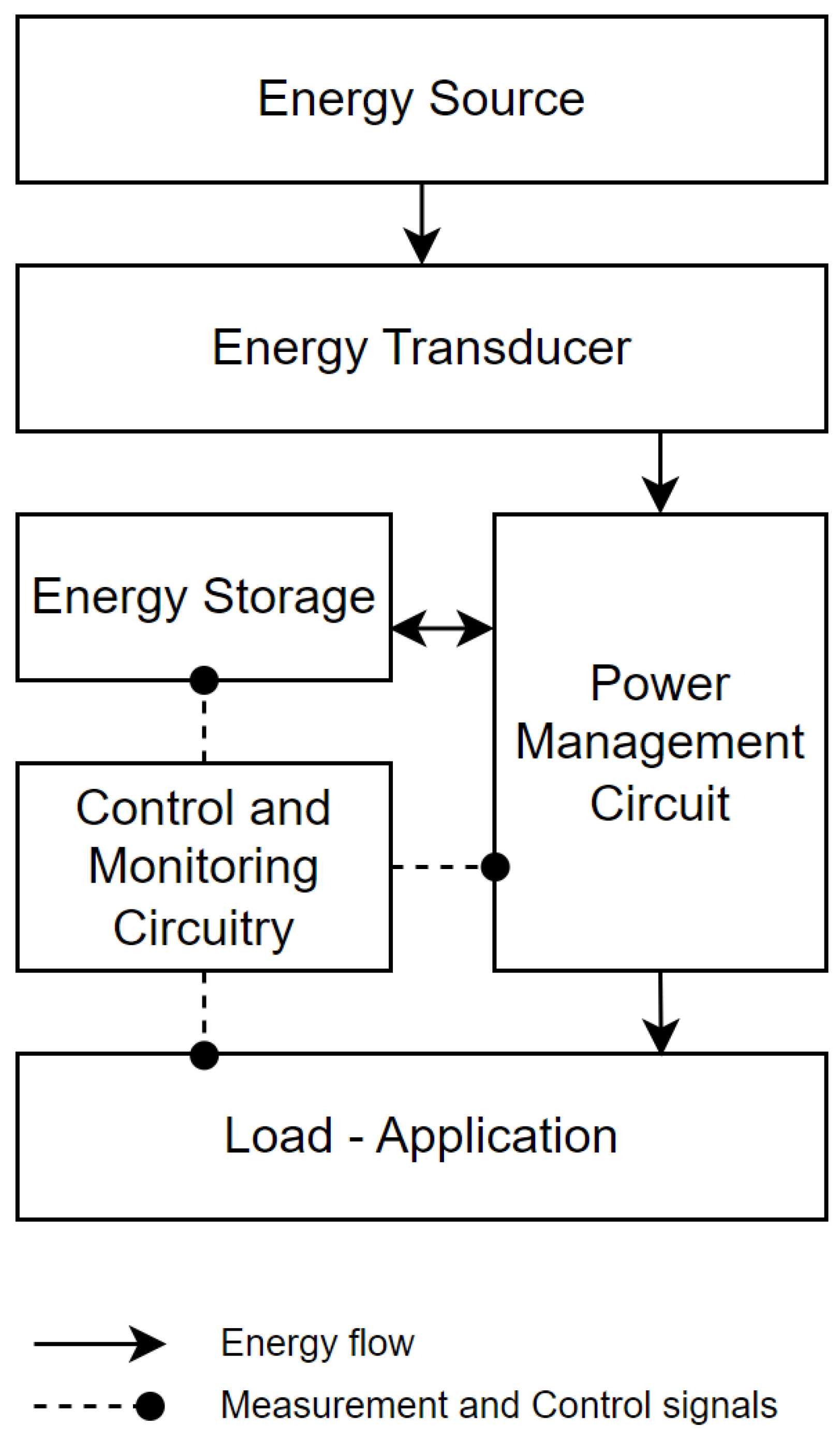
Figure 1. Generalized energy harvesting system.
Energies 18 04467 g001
Figure 2. A possible classification of energy sources.
Energies 18 04467 g002
Figure 3. Energy sources usage in the past and future [28].
Energies 18 04467 g003
Figure 4. Photovoltaic cell.
Energies 18 04467 g004
Figure 5. Mechanical stress applied to a piezoelectric material.
Energies 18 04467 g005
Figure 6. Thermoelectric cell.
Energies 18 04467 g006
Figure 7. Contact modes [90].
Energies 18 04467 g007
Figure 8. Triboelectric effect.
Energies 18 04467 g008
Figure 9. Electromagnetic transducers [123].
Energies 18 04467 g009
Figure 10. Vibrational energy harvesting of electromagnetic transducer [143].
Energies 18 04467 g010
Figure 11. Energy storage systems.
Energies 18 04467 g011
Table 1. Comparison of energy source types.
Energy SourceRenewableMain Input EnergyEfficiency [%]Power DensityEnviromental ImpactApplications
Fossil fuelsNoChemical reaction of combustion30–50HighHigh (CO2, pollution)Fossil fuel power plants, combustion engines
NuclearNoNuclear fission reaction33–37HighNowadays Low-Medium (radioactive waste)Nuclear power plants
PhotovoltaicYesPhotovoltaic energy6–4160–200 W/m2Low (toxic if mishandled)Solar panels, farms
PiezoelectricYesMechanical stress60–8010–1000 μ W/m2Low–MediumWearables, roads, lighters
ThermoelectricYesThermal gradient5–60.1–5 W/m2Low–MediumWaste heat, sensors
TriboelectricYesMechanical motion70–85100–11,130 W/m2Low–MediumWearables, sensors, buoys
ElectromagneticYesMagnetic inductionVariableVariableLowGenerators, sensors
Disclaimer/Publisher’s Note: The statements, opinions and data contained in all publications are solely those of the individual author(s) and contributor(s) and not of MDPI and/or the editor(s). MDPI and/or the editor(s) disclaim responsibility for any injury to people or property resulting from any ideas, methods, instructions or products referred to in the content.