Article

Fitness-for-Service Assessment of Hoop-Wrapped Vessel with Metal Liner in High-Pressure Hydrogen Environment

1
School of Mechanical and Power Engineering, East China University of Science and Technology, Shanghai 200237, China
2
4H Hydrogenation Material Laboratory, Shanghai 201306, China
*
Authors to whom correspondence should be addressed.
Energies 2025, 18(17), 4463; https://doi.org/10.3390/en18174463
Submission received: 28 June 2025 / Revised: 9 August 2025 / Accepted: 20 August 2025 / Published: 22 August 2025
(This article belongs to the Section A5: Hydrogen Energy)

Abstract

Hoop-wrapped vessels with metal liners (Type II vessels) are susceptible to the risks of brittle fracture and fatigue failure in high-pressure hydrogen environments. However, there is limited research concerning fitness-for-service (FFS) assessments of Type II vessels. An FFS assessment was conducted on a specific Type II vessel designed for high-pressure hydrogen storage. The mechanical properties of the liner material 4130X were obtained through in situ mechanical testing in a hydrogen environment. Based on the measured data, the stress distribution within the Type II vessel under different working conditions was determined using a finite element analysis by ANSYS Workbench 2019 R2 software. A leak-before-burst (LBB) analysis and a brittle fracture assessment of the Type II vessel were performed using the failure assessment diagram (FAD) methodology. The results indicate that the measured fracture toughness of 4130X under high-pressure hydrogen is 46 MPa·m0.5, which is significantly lower than the 178 MPa·m0.5 required for LBB failure for the studied vessel. However, the vessel remains in a safe state when the crack depth is under 3.03 mm. Furthermore, the remaining fatigue life of a Type II vessel containing a crack was calculated. The relationship between the non-destructive testing (NDT) capability requirement and the inspection interval for this type of vessel was explored, providing references for establishing inspection schedules for Type II vessels.

1. Introduction

Amid the global transition toward cleaner energy systems, hydrogen’s advantage of zero emissions has led many countries to prioritize hydrogen industry development [1,2,3]. Currently, the major constraint on scaling up the hydrogen industry is hydrogen storage and transportation [4]. The current hydrogen storage methods include hydrogen compression storage through high pressure, hydrogen liquefaction storage through low temperature, and hydrogen storage through physical or chemical adsorption. High-pressure gaseous storage, the most widely deployed technology, offers low cost and operational convenience [5]. High-pressure hydrogen storage vessels, the core components of high-pressure hydrogen storage technology, are predominantly manufactured by single-layer monolithic spinning or integral forging [6,7]. However, as hydrogen storage pressure increases, single-layer vessels face challenges including inhomogeneous cooling during the heat treatment of thick-walled sections [8] and prohibitively difficult non-destructive testing (NDT) of the inner surface [6]. Hoop-wrapped vessels with metal liners (hereinafter referred to as Type II vessels), featuring a metal liner overwrapped with a circumferentially wrapped fiber-reinforced plastic layer specifically on the cylindrical section to carry the circumferential load [9], offer a solution. This design facilitates wall thickness reductions and weight savings. Consequently, it has not only found application in stationary hydrogen storage [10] but also holds significant market potential for mobile storage systems. For Type II vessels, relevant standards such as ISO 14687 require high purity of hydrogen storage (e.g., ≥99.97% [11]). Similarly, metallic hydride systems often necessitate high-purity hydrogen (≥99.99%) to prevent surface passivation and capacity loss [12].
The metal material of the hydrogen storage vessel is prone to cracking due to hydrogen embrittlement, which eventually leads to brittle fracture [13]. The brittle fracture of the hydrogen storage container not only destroys the integrity of the container structure, but also provides a leakage channel for high-pressure hydrogen, which eventually leads to catastrophic physical rupture and leakage accidents [14]. Therefore, it is important to carry out the experiments on the mechanical properties of materials under a hydrogen environment, especially the fracture performance test. At present, domestic and foreign testing standards such as ISO 11114-4, AN-SI/CSA CHMC 1, and ASME VIII-3 KD-10 have been issued [15].
For Type II vessels, chromium–molybdenum (Cr-Mo) steel is typically employed as the liner material. This high-strength steel offers good hardenability [16], satisfying high-pressure operational requirements. However, its body-centered cubic lattice structure exhibits marked toughness deterioration in high-pressure hydrogen environments [17]. Research institutions, for example, including Sandia National Laboratories [18], Japan’s National Institute of Advanced Industrial Science and Technology (AIST) [19], Zhejiang University [20,21], and the China Special Equipment Inspection and Testing Institute (CSEI) [22], have conducted fracture toughness and fatigue crack growth rate tests on various Cr-Mo steel grades under high-pressure hydrogen environments. Experimental results demonstrate that Cr-Mo steel exhibits significantly reduced fracture toughness under high-pressure hydrogen, manifesting brittle embrittlement characteristics. Concurrently, fatigue crack growth rates in high-pressure hydrogen environments are substantially accelerated compared to ambient air conditions. Consequently, pre-existing flaws in Cr-Mo steel vessels may trigger low-stress brittle fracture or accelerated fatigue crack propagation in high-pressure hydrogen environments, critically compromising structural integrity. Furthermore, a series of pressure-cycle fatigue tests conducted by the CSEI on flawed Type II vessels revealed significantly reduced residual fatigue life compared to single-layer vessels under identical conditions. For instance, a tested Type II vessel containing 0.6 mm cracks exhibited merely 2600 cycles to failure—over an order of magnitude lower than the 15,000-cycle endurance of single-layer vessel with equivalent flaws. In summary, for the Type II vessels serving in a high-pressure hydrogen environment the toughness degradation caused by hydrogen embrittlement and the potential failure risk of its own structure make it difficult to ensure its structural safety in a high-pressure hydrogen environment. It is necessary to carry out a fitness-for-service (FFS) assessment to determine its safety under service conditions.
FFS assessment constitutes a quantitative engineering methodology that verifies structural reliability during component operation. This fracture-mechanics-based integrity evaluation focuses on flawed components, determining their continued operational viability against standardized acceptance criteria. So far, research has been conducted on the fitness-for-service assessment of the components working in hydrogen environments. Pan et al. [23] performed a fitness-for-service assessment on a hydrogen buffer tank within a hydrogenation reactor containing buried defects, concluding that the replacement of the defective area was necessary. Qian et al. [24] assessed the serviceability of a 13.5 MPa hydrogen storage spherical vessel with buried defects at a hydrogen production station and supported the continued service of the vessel with defects. Based on a failure assessment diagram (FAD), Wang et al. [25] applied different standards to calculate the residual fatigue life of hydrogen storage vessels, explored the discrepancies between these standards, and proposed corresponding correction methods. Separately, Brown et al. [26] performed an FFS assessment on a flange groove containing hydrogen-assisted cracking within a hydrogenation vessel, and they clarified the variation in the crack driving force with crack depth in the flange’s local high-stress region. Esmaeely et al. [27] discussed the technical difficulties in the FFS assessments of existing natural gas pipelines for hydrogen transport. Kappes et al. [28] quantified the effects of hydrogen blending for pipelines on critical failure loads and critical defect sizes through an FFS assessment.
Although the abovementioned studies involved FFS assessments of diverse hydrogen-related components, their research scope remains predominantly confined to low-pressure petrochemical infrastructure (e.g., pipelines and storage vessels). Such components typically operate under low hydrogen pressures and are fabricated from ferritic steels. This differs from high-pressure hydrogen storage vessels that need to work under high hydrogen pressure and are made from high-strength steel. The degradation of material properties caused by hydrogen between them is also different. Therefore, it is necessary to combine the material performance parameters to more closely reflect the actual situation when conducting the FFS assessment. Furthermore, due to the inherent structural complexity of Type II vessels, obtaining analytical stress solutions in the liner under mechanical constraint from the hoop-wrapped composite layer is difficult. This complexity fundamentally impedes accurate FFS assessment for high-pressure hydrogen storage applications. Consequently, current research on the integrity of hydrogen storage vessels remains predominantly focused on single-layer vessels, with critically insufficient assessment of Type II vessels. The absence of FFS assessment protocols for such vessels poses significant risks to in-service structural integrity assurance. Consequently, research on the integrity assessment of Type II vessels is imperative. Thus, in this study a methodological framework for the FFS assessment of these vessels is established.
In this study, a Type II vessel with Cr-Mo steel as the liner material was taken as the research object, and the risk of brittle fracture and fatigue failure under a high-pressure hydrogen environment was evaluated. The mechanical properties of Cr-Mo steel were obtained via a mechanical properties test. Based on the measured material mechanical properties, the stress distribution of the studied Type II vessels under various working conditions was obtained based on finite element analysis (FEA). The FAD method was used to assess the leak-before-burst and brittle fracture failure of the studied vessel. The residual fatigue life of the studied Type II vessel with cracks was further calculated, and the relationship between the defect detection ability and the detection cycle of the NDT was explored.

2. Materials and Methods

2.1. Experimental Setup

2.1.1. Material Specifications

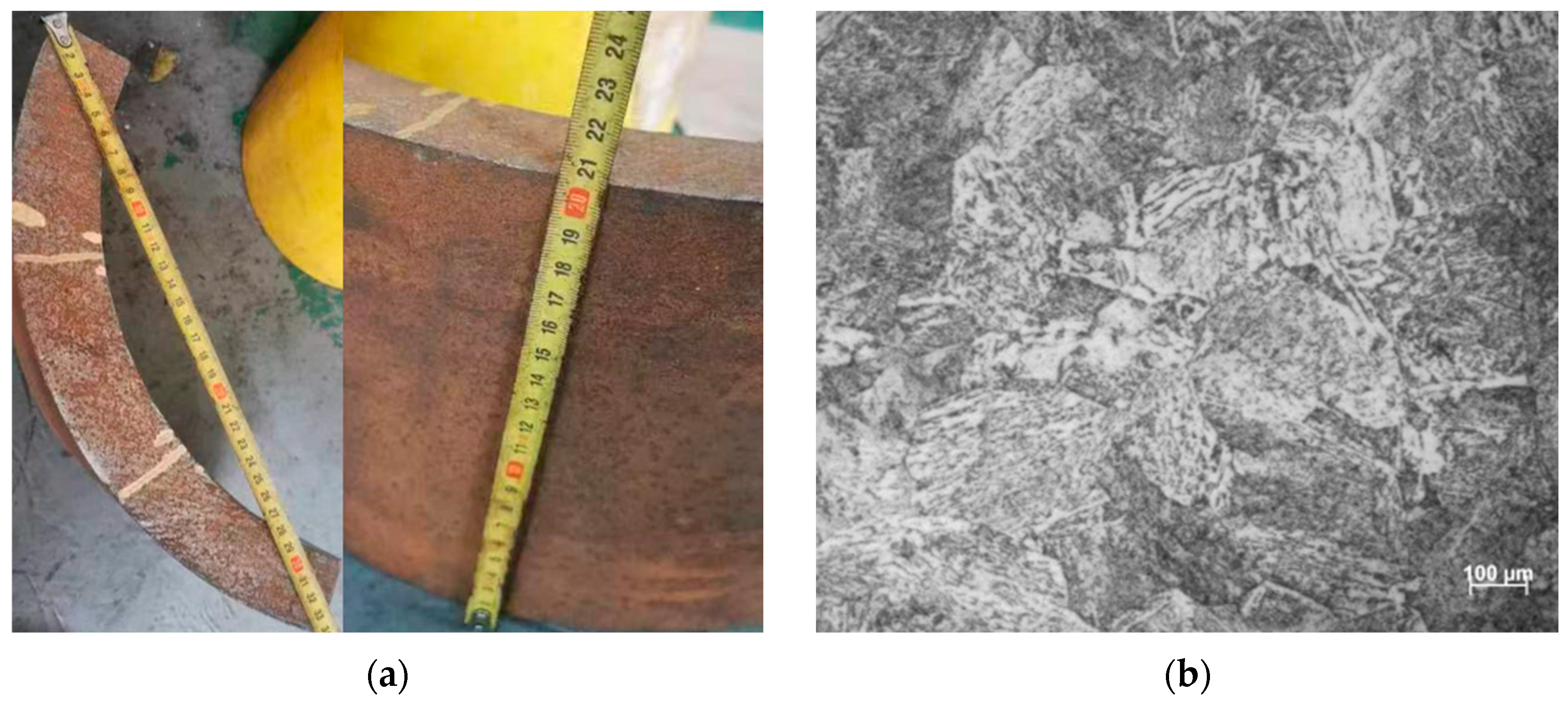
A Type II vessel developed by our team was taken as the research object, which is an industry-commissioned prototype that has completed structural validation but has not yet entered commercial use. Its liner is made of 4130X, a type of Cr-Mo steel. The liner material (from Shanghai Institute of Special Equipment Inspection and Research, Shanghai, China) is shown in Figure 1a; it exhibits a characteristic tempered sorbite microstructure (Figure 1b). Its chemical composition is listed in Table 1.
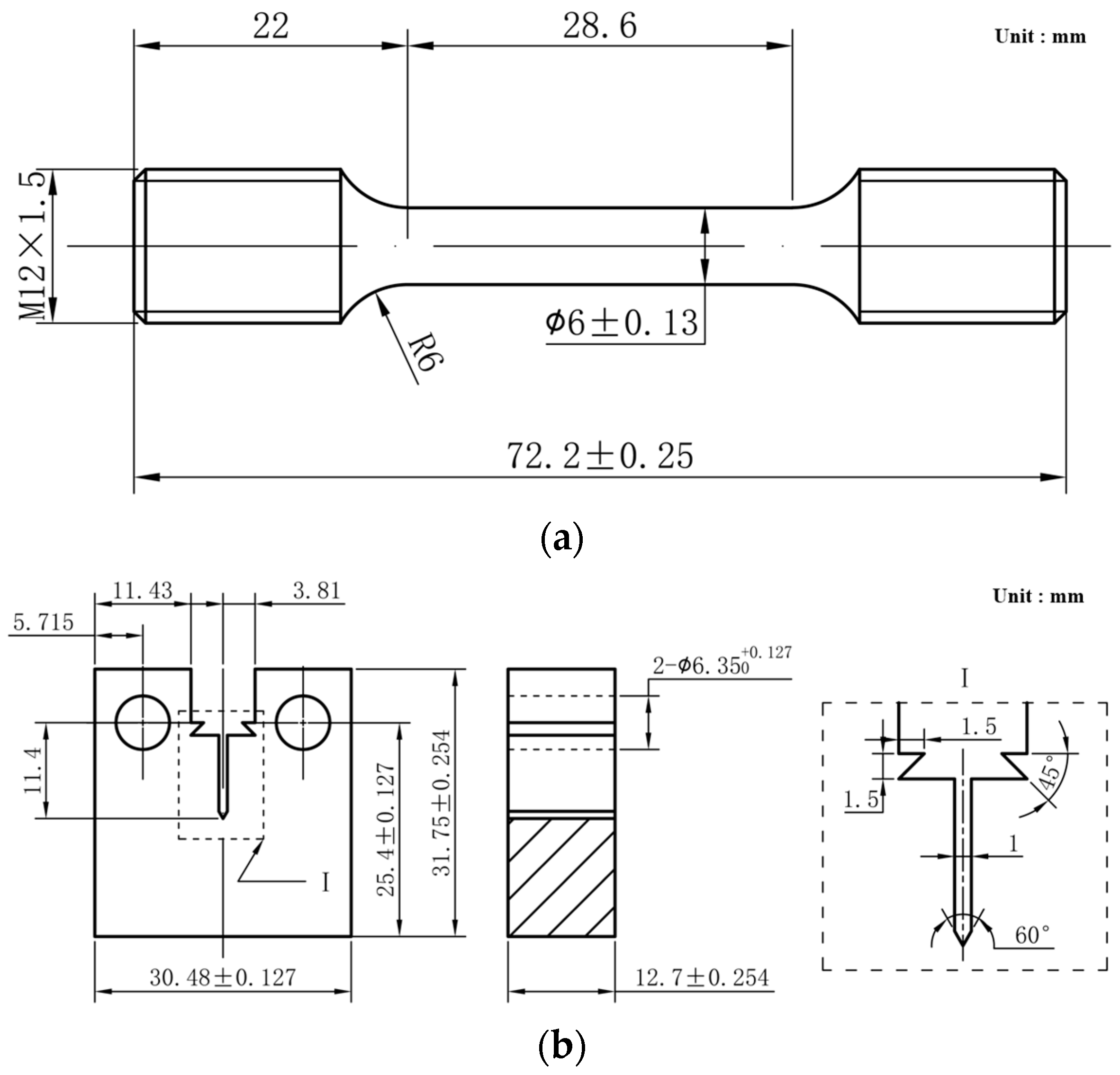
A slow strain rate tensile (SSRT) test, fracture toughness test, and fatigue crack growth rate (FCGR) test were carried out on the material in air and in a 100 MPa hydrogen environment. The dimensions of the smooth rod tensile specimen and the compact tension (CT) specimen used are shown in Figure 2.

2.1.2. Testing System and Experimental Methodology

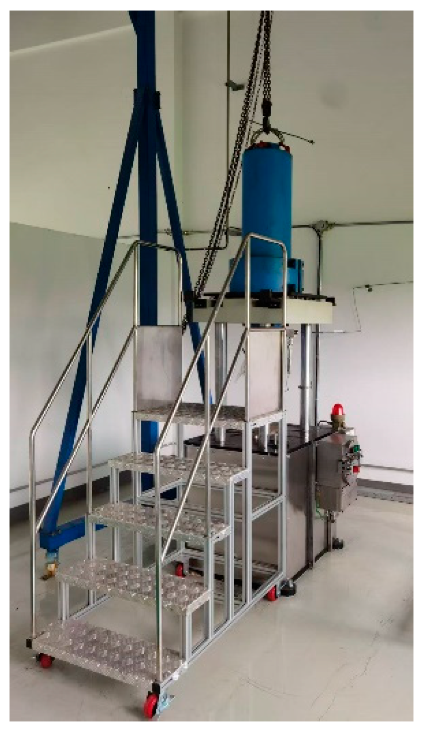
A mechanical property test of the liner material in this study was conducted using a test system for high-pressure hydrogen environment materials (from Shanghai Electric Nuclear Power Group Co., Ltd., Shanghai, China), as shown in Figure 3. The SSRT test was performed according to the requirements of GB/T 228.1-2021 [29], and the tensile rate was 2 × 10⁻⁵/s. A fracture toughness test was carried out according to the requirements of GB/T 21143-2014 [30], and the test rate was 0.04 mm/min. The FCGR test was carried out according to the requirements of GB/T 6398-2017 [31], and the loading frequency was 0.1 Hz. Following specimen mounting, the environmental chamber was purged with high-purity nitrogen and subsequently pressurized with hydrogen to the target test pressure. Since the design pressure of the vessel studied in this paper is 99 MPa, and the hydrogen environment pressure of the material performance test should not be lower than the design pressure, the test pressure used in this paper is 100 MPa. The system was held for 30 min to stabilize hydrogen–material interactions prior to mechanical loading. To overcome the inherent signal drift of conventional strain-based transducers in high-pressure hydrogen environments [32,33], hydrogen-resistant sensors were used. These sensors are unaffected by hydrogen intrusion, guaranteeing metrological traceability and data fidelity under extreme hydrogen conditions.

2.2. Numerical Modeling

2.2.1. Geometric Modeling

A Type II vessel for a hydrogen refueling station developed by our team was taken as the research object in this study. It is a prototype vessel that has not yet entered commercial use. The Type II vessel is composed of a 4130X steel liner and a carbon-fiber-reinforced plastic laminate. The design parameters of the vessel are based on the process parameters of the hydrogen refueling station expected to be put into use. The design pressure and operation pressure of the Type II vessel are 99 MPa and 91 MPa, and the hydrostatic test pressure is 124.9 MPa. According to the hydrogen charging and discharging conditions of the vessel in the service process of the hydrogen refueling station, the fatigue load cycle considered in the vessel is 70~91 MPa, and its fatigue life is required as 11 cycles per day for 5 years, or a total of 15,000 cycles. The length and the inner diameter of the vessel are 5.5 m and 0.356 m, with a volume of 500 L. The thickness of the liner is 0.025 m. The carbon fiber laminate consists of 80 layers with a stacking sequence 90° of winding angle with an equal thickness of 0.285 mm. The total thickness is 0.0228 m, corresponding to the wall thickness of the Type II vessel’s external layer. The liner material adopts the tensile properties of 4130X in the 100 MPa hydrogen environment measured above; the material parameters of the laminate are shown in Table 2. Considering that the structure and load of the vessel are axisymmetric, only a 1/8 model was established for analysis. The model structure diagram is shown in Figure 4.

2.2.2. Mesh Generation

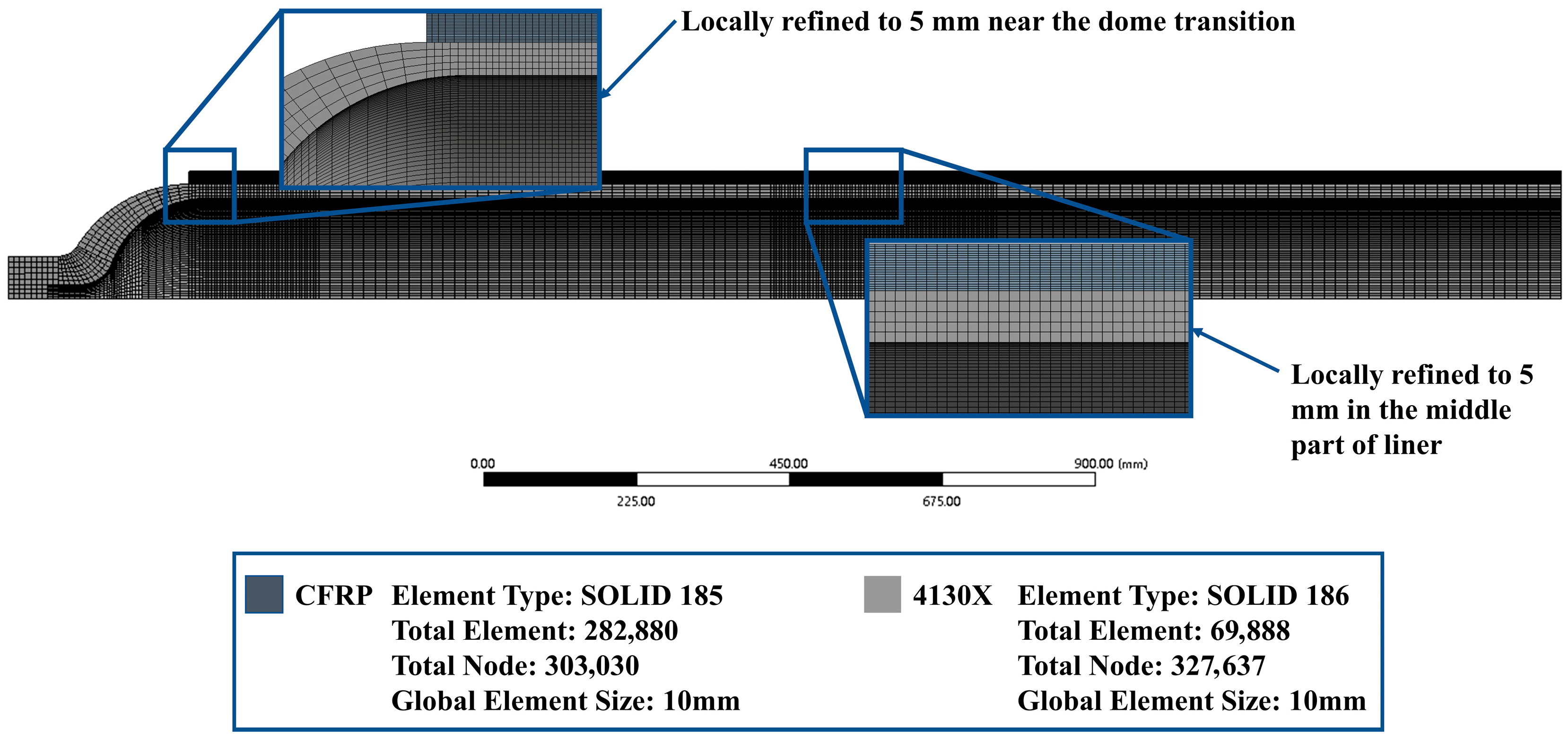
The stress analysis of the Type II vessel required separate meshing of the liner and composite hoop-wrapped layer, with subsequent assembly coupling. The statics module and ACP module of ANSYS Workbench 2019 R2 were used for analysis. Figure 5 details the mesh configuration. The composite overwrap employed SOLID185 elements, while the liner used SOLID186 elements. The mesh model contained 630,667 nodes and 352,768 elements, with the liner comprising 327,637 nodes and 69,888 elements.

2.2.3. Boundary Condition

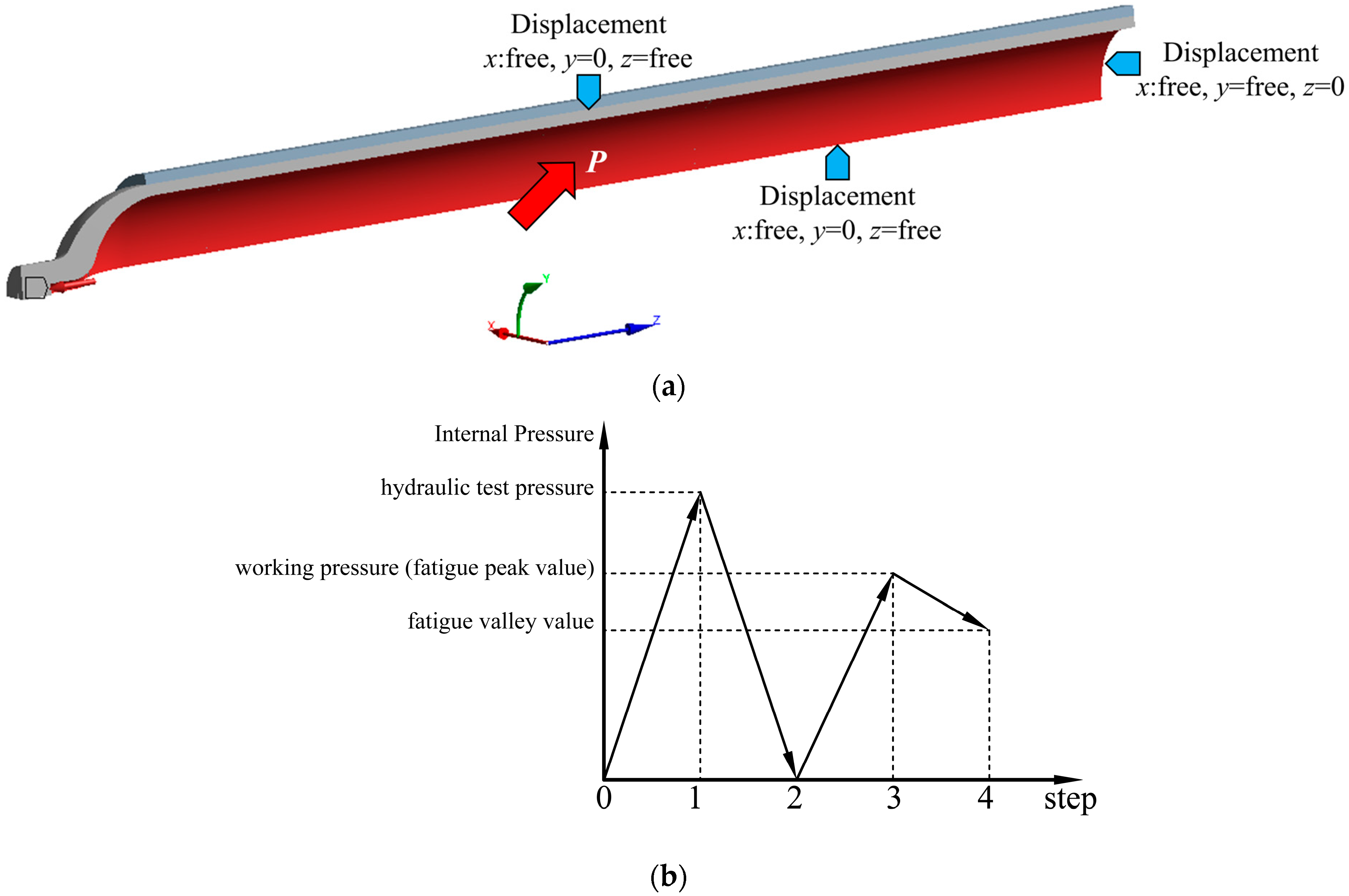
Figure 6a shows the boundary condition setting of the Type II vessel. The normal displacement constraint is applied on the section of the model, and the specified pressure is applied on the inner surface of the liner. The bond constraints are applied between the cylinder part of the liner and the laminate layer to simulate a close fit between them. The loading step of the vessel in the analysis process is shown in Figure 6b. The actual service conditions of the vessel are simulated by the loading step of hydraulic test pressure–unloading–working pressure (fatigue peak value)–fatigue valley value.

2.3. Fitness-for-Service Assessment Methods

2.3.1. Failure Assessment Diagram Methodology

Given the prior studies which documented 4130X steel exhibiting a reduction in toughness under high-pressure hydrogen environments, a fitness-for-service (FFS) assessment of the Type II pressure vessels under investigation becomes essential to ensure structural integrity.
The failure assessment diagram (FAD) methodology employed in this study provides a quantitative framework for evaluating the structural integrity of defective components by simultaneously accounting for applied load and material fracture resistance. The safety of the studied vessel is determined by judging whether the vessel meets the leak-before-burst (LBB) condition and whether the specified crack size leads to brittle fracture under the working pressure.
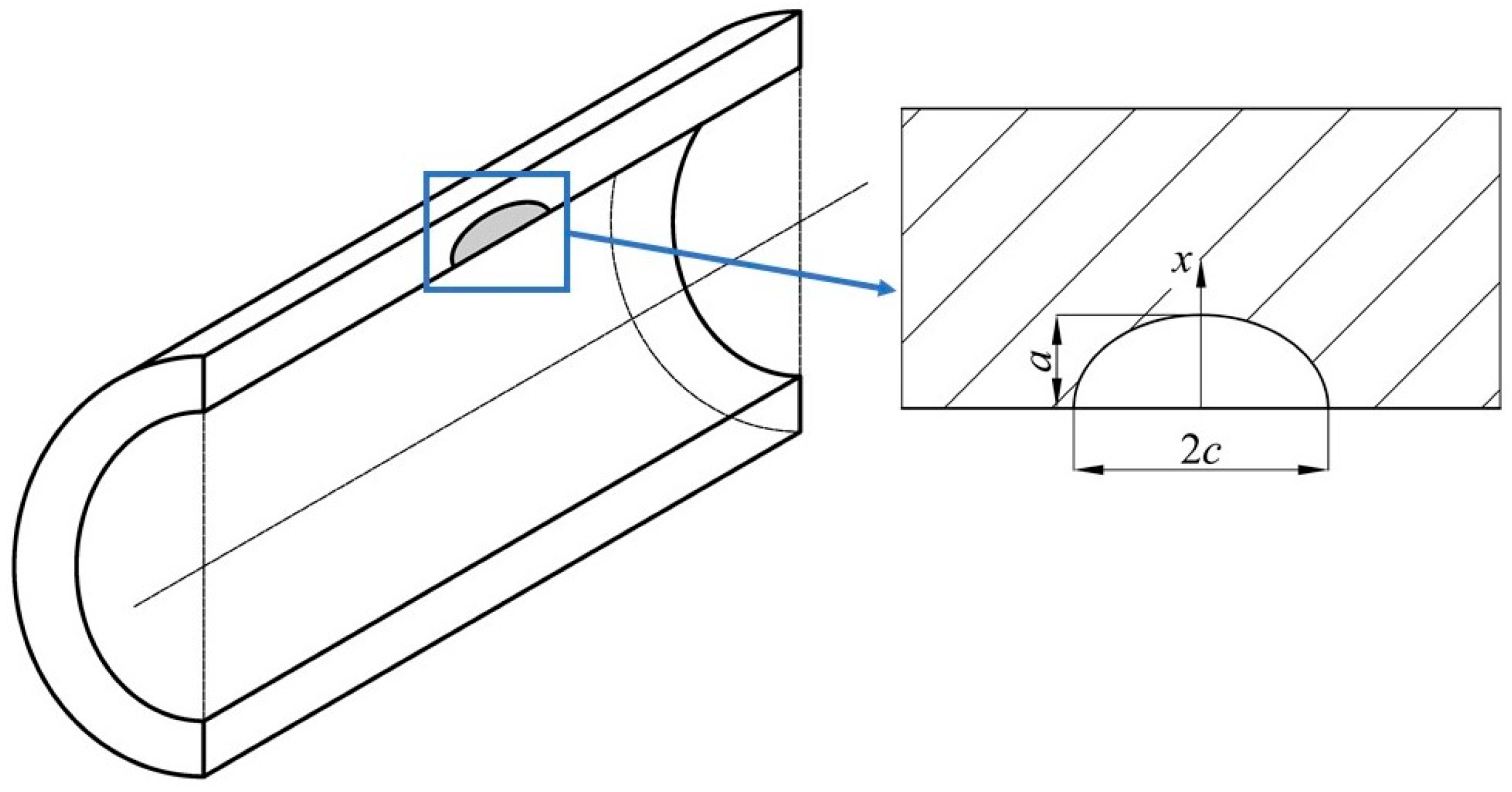
In order to calculate the stress intensity factor, it is necessary to assume the crack form of the structure. According to American Society of Mechanical Engineers (ASME) Section VIII Division 3 KD-411 [34], it is assumed that there is an axial semi-elliptical surface crack on the inner surface of the liner, as shown in Figure 7. The ratio of crack depth a to length 2c is 1/3.
The failure assessment curve (FAC) used in this study adopts the curve in API 579-1/ASME FFS-1 [35] with conservatism (as shown in Equation (1)). Here, Kr is the fracture ratio and L r P are the load ratio of primary stress, as shown in the following Equations (2) and (3):
K r = 1 0.14 L r P 2 0.3 + 0.7 exp 0.65 L r P 6
K r = K I P + Φ K I S R K m a t
L r P = σ r e f P σ y s
where K I P and K I S R are the stress intensity factor of primary stress and secondary stress, respectively, which can be calculated using API 579-1 Appendix 9B.5.11. Φ is the plasticity correction factor, which can be obtained according to API 579-1 Section 9.4.3.2. σ r e f P is the primary stress reference stress and can be calculated using API 579-1 Appendix 9C.5.11. σys and Kmat are the yield strength and fracture toughness of the material, respectively.
It is noteworthy that a polynomial fitting-based approach for calculating stress intensity factors and reference stresses was employed in this study. This approach fits the far-field stress on the crack propagation path by polynomial, and the stress intensity factor and the reference stress are calculated by the stress distribution coefficient obtain by this approach. The far-field stress profiles utilized are derived from finite element analysis (FEA) results of the investigated vessel, which explicitly accounts for the interaction between internal liner and external laminate layers. This methodological distinction from monolayer vessel assessments constitutes a key innovation in this assessment framework.
In addition, the cut-off line expression of the curve is as follows (Equation (4)), where σf is the flow stress, and the flow stress in this study is half of the sum of the yield strength and tensile strength of the material. L r ( m a x ) P means the maximum value of L r P
L r max P = σ f σ y s
Through the calculation of the above formula, the assessment point of the structure under the specified load condition and crack size can be obtained. If the assessment point is located below the FAC, the structure is still considered to be in a safe state. On the contrary, if it is above then it is considered that the structure cannot continue to be used.

2.3.2. Fatigue Life Analysis Methodology

According to the requirements of ASME Section VIII Division 3 KD-10 [34], the fatigue life of pressure vessels for high-pressure hydrogen storage shall be analyzed using the fracture mechanics design approach. Therefore, referring to the relevant content of ASME Section VIII Division 3 KD-4 [34], the fracture mechanics design method was adopted to perform fatigue life analysis on the investigated subject, with the analysis procedure illustrated in Figure 8. Considering that the liner in Type II vessels directly contacts the working medium and that leakage accidents caused by its fatigue failure may lead to severe hazards, the fatigue life of the liner is assumed to characterize that of the entire vessel in this study.
When crack depth a extends to 0.8 times the wall thickness of the liner, or the calculated stress intensity factor KI is greater than or equal to the fracture toughness of the material, or the assessment point calculated by the current crack depth reaches FAC and above, it is considered that the Type II vessel has fatigue failure. The corresponding crack depth at this threshold is defined as the critical crack depth ac. Two limit conditions are used to determine the design fatigue life Nd. The first condition considers the cycles Nc from the initial crack a0 to the critical depth ac. The other condition accounts for the cycle Np from the initial crack a0 to the assigned crack with depth of (0.75 a0 + 0.25 ac). Then the design life Nd is determined by the minimum of Np and Nc/2.
The stress distribution perpendicular to the crack plane along the crack propagation path in the liner without cracks is obtained through FEA. This stress distribution is substituted into Equation (5) to determine the corresponding fitting coefficients Ai (i = 0, 1, 2, 3), which are then incorporated into Equation (6) to calculate the stress intensity factor KI at the current crack depth. The equations are as follows:
σ = A 0 + A 1 x / a + A 2 x / a 2 + A 3 x / a 3
K I = A 0 + A p G 0 + A 1 G 1 + A 2 G 2 + A 3 G 3 π a Q
where x presents the distance through the wall measured from the component surface nearest the crack, Gi (i = 0, 1, 2, 3) denote surface correction coefficients, Ap is the internal pressure of the vessel, and Q signifies the crack shape factor. For parameters Gi and Q, due to their applicability being strictly limited to crack depth-to-length ratios within 0–0.5, their values corresponding to a crack depth-to-length ratio of 0.5 are retained when the actual ratio exceeds 0.5. The maximum and minimum stress intensity factors (KImax and KImin) in the fatigue load cycle are substituted into the Paris formula shown in Equation (7), which is as follows, to calculate the required number of cycles for a specified crack extension:
d a d N = C f R k K Imax K Imin m
where f(Rk) denotes the function characterizing the influence of stress ratio Rk on fatigue crack growth behavior, whose mathematical expression is formulated as:
f R k = 1 + 3.53 R k R k 0 1.5 1.5 R k m R k < 0
where the expression of the stress ratio Rk is as follows:
R k = K Imax K Imin
Referring to relevant contents of ASME Section VIII Division 3 KD-4 [34], an initial surface semi-elliptical crack was assumed to be present in the liner. Since the assumption of initial crack depth is related to the NDT capability used, this study refers to the requirements for detection capability in GB/T 44457-2024 [36], and it assumes that when the initial crack depth a0 = 1 mm then the initial crack depth–length ratio was 1/3.

3. Results and Discussions

3.1. Material Characterization

3.1.1. SSRT Test

The stress–strain curves of 4130X in an air environment and a 100 MPa hydrogen environment obtained through the SSRT test are shown in Figure 9. It can be seen in Figure 8 that, for the 100 MPa hydrogen environment, the stress–strain curve contains the complete uniform plastic deformation stage as the curve in the air environment.
Table 3 lists the tensile properties of 4130X in air and high-pressure hydrogen environments. It can be seen in Table 3 that the strength of 4130X only changes slightly in the high-pressure hydrogen environment. For the yield strength, 4130X in the 100 MPa hydrogen environment increased by 2.65% compared with the air environment. The tensile strength of 4130X in the 100 MPa hydrogen environment was 1.81% higher than that in the air environment. However, for the toughness index, there was a significant difference between the air environment and hydrogen environment. The elongation and reduction in area of 4130X decreased by 61.73% and 37.95%, respectively, in the 100 MPa hydrogen environment, which means that the 4130X exhibited no large plastic deformation during fracture in the high-pressure hydrogen environment and that its fracture mode was more inclined toward brittle fracture. Similar trends have also been observed in the study of Zhejiang University [21], which proves that the data results obtained in this paper have a certain degree of reliability. Therefore, it can be seen that for 4130X the influence of the high-pressure hydrogen environment is mainly reflected in its toughness, with no obvious toughness impairment being observed.

3.1.2. Fracture Toughness Test

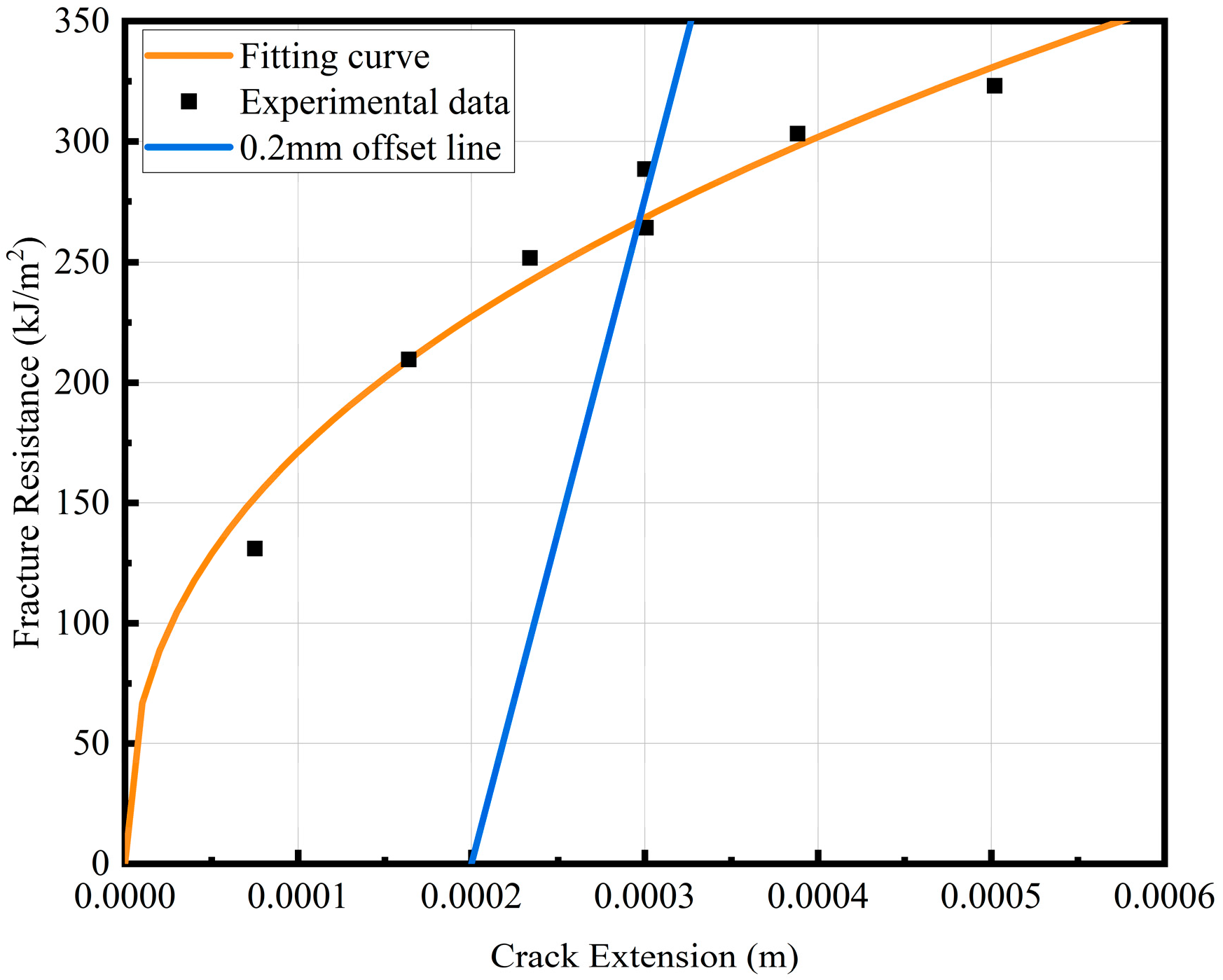
As per GB/T 21143-2014 [30], the plane strain fracture toughness KIC of 4130X in air could not satisfy the validity criteria. Consequently, a multi-specimen resistance curve (R-curve) methodology was implemented to characterize crack growth resistance. J0.2BL, which means the J integral corresponding to the crack stable propagation of 0.2 mm, is defined as the fracture initiation toughness to provide an equivalent fracture toughness metric when KIC measurement is impractical. The J0.2BL = 266 kJ/m2 of 4130X in the air environment was calculated. According to the standard verification, the calculated J0.2BL is effective and non-size sensitive. In order to facilitate the comparison with the fracture toughness of the 100 MPa hydrogen environment, Equation (10) was used to convert J0.2BL into KIC, where E is the elastic modulus of material and v is the Poisson ratio of material. The R-curve in air is shown in Figure 10.
K IC = J 0.2 BL E 1 v 2
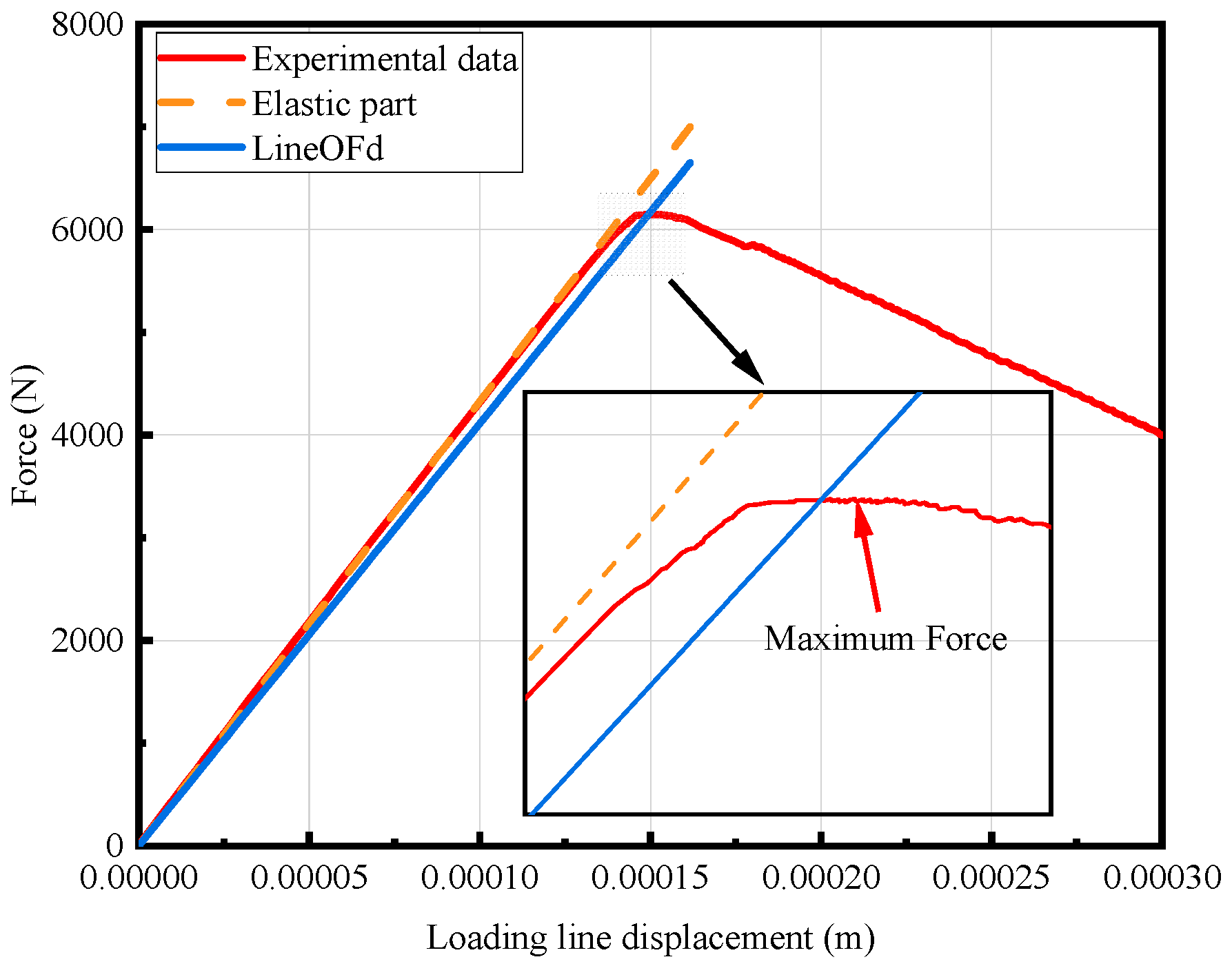
The loading line displacement–load curve of the fracture toughness test process in a 100 MPa hydrogen environment is shown in Figure 11. The calculated KIC is verified according to the requirements of GB/T 21143-2014 [30]. The verification results show that the test results meet the validity requirements of plane strain fracture toughness. Therefore, the fracture toughness of 4130X in the 100 MPa hydrogen environment was calculated to be 46 MPa·m0.5.
Table 4 summarizes the fracture toughness of 4130X under air and 100 MPa hydrogen environments. The data reveal a devastating 80.99% reduction in the fracture toughness of 4130X when exposed to a 100 MPa hydrogen environment. Crucially, the measured fracture toughness in the 100 MPa hydrogen environment is below the threshold of 50 MPa·m0.5 stipulated in GB/T 44457-2014 [36] for Cr-Mo steels operating at design pressure. The results fully illustrate the serious deterioration of the fracture toughness of 4130X under hydrogen conditions, demonstrating the risk of brittle fracture in high-pressure hydrogen environments.
Table 5 compares the fracture toughness of 4130X obtained in this study under a 100 MPa hydrogen environment with the data of 4130X under a similar environment reported in the literature. It can be seen that the difference between the 4130X obtained in this experiment and the data published in the literature is small. Therefore, it can be considered that the data obtained in this study has certain reliability. At the same time, by comparing with the data in the air environment, it can be seen that it is a common phenomenon that the fracture toughness of 4130X decreases significantly in the high-pressure hydrogen environment. Therefore, it is necessary to carry out FFS assessment for 4130X steel vessels serving in a high-pressure hydrogen environment.

3.1.3. FCGR Test

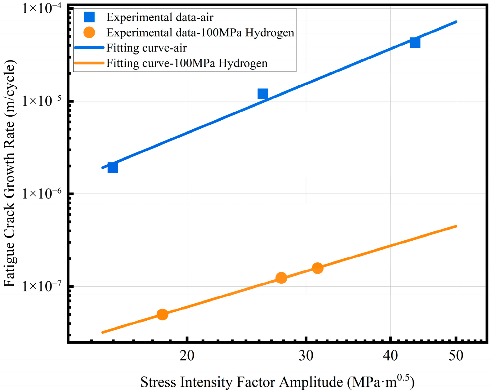
A series of standard 0.25T CT specimens with identical initial crack lengths were tested under different fatigue loads in the constant fatigue cycle, and the crack propagation length was recorded. The crack propagation velocity and average crack length of the different fatigue loads were calculated according to the secant method described in GB/T 6398-2017 [31]. The obtained results were linearly fitted using a logarithm, and the Paris formula parameters C and m in the stable crack propagation stage were obtained. The relationship between the fatigue crack growth rate and the stress intensity factor amplitude ΔK of 4130X in an air and a 100 MPa hydrogen environment is shown in Figure 12. The Paris formula parameters of 4130X in the air and hydrogen environments are listed in Table 6. The fatigue crack growth rate of 4130X exhibits catastrophic acceleration in the high-pressure hydrogen environment, representing a two-orders-of-magnitude elevation in FCGR under the same ΔK. This result proves that 4130X has a non-negligible risk of fatigue failure in hydrogen environments.
The data in this study are further compared with the published FCGR data of 4130X under high-pressure hydrogen environment. As shown in Table 7, the FCGR of 4130X obtained in this study is lower than the data in the literature. Results show that even if it is 4130X, there are still some differences in FCGR under a high-pressure hydrogen environment. However, compared with the data in the air environment, the above results demonstrate that it is a common phenomenon that the FCGR of 4130X exhibits a significant acceleration trend in a high-pressure hydrogen environment, which means that the vessels manufactured by 4130X are more prone to fatigue failure in a high-pressure hydrogen environment. Therefore, it is necessary to predict its fatigue life and conduct regular NDT during service to avoid accidents.

3.2. Fractographic Analysis in High-Pressure Hydrogen

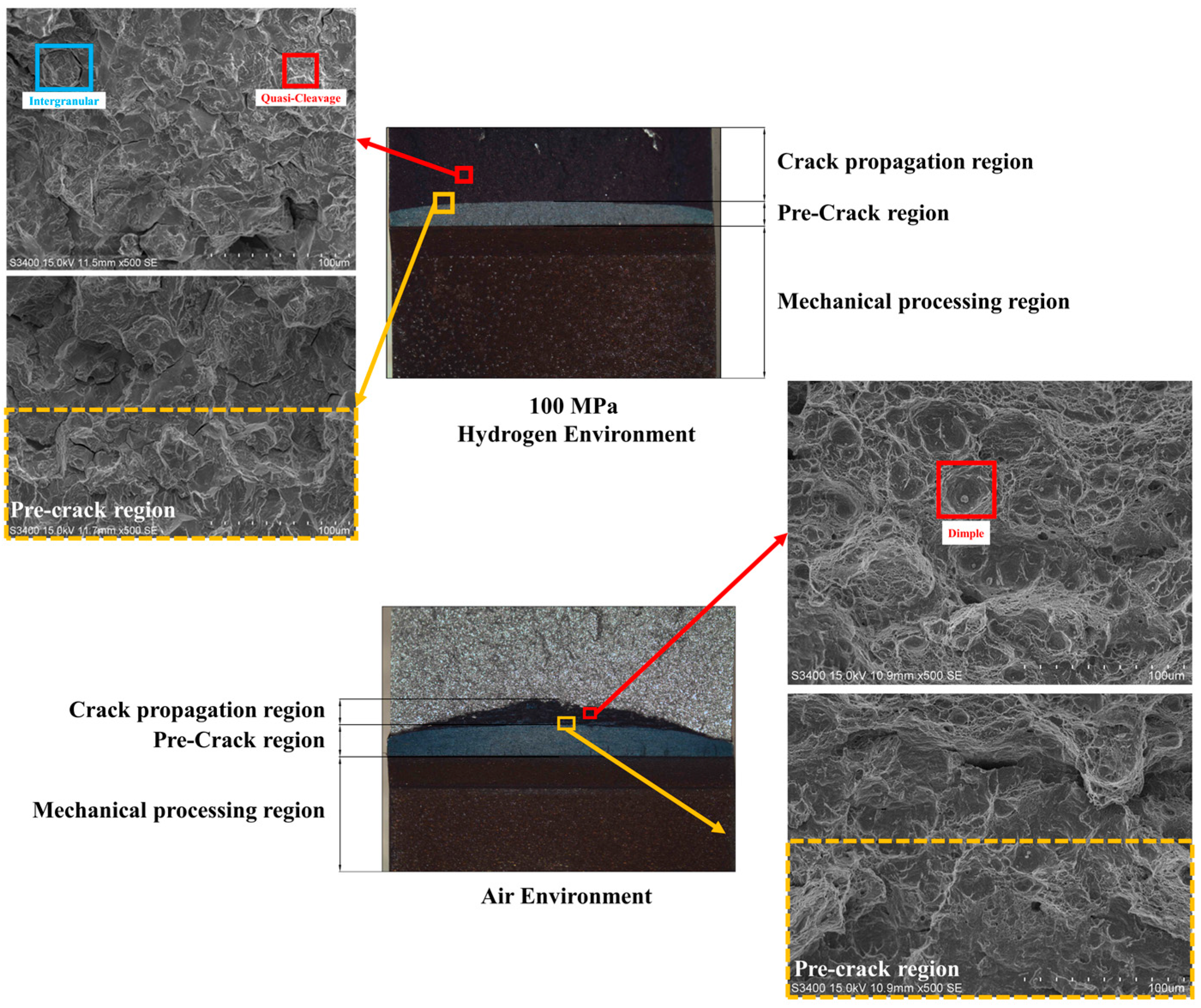
In a previous study, the hydrogen embrittlement sensitivity of 4130X in a high-pressure hydrogen environment was revealed by comparing the results of the mechanical properties test in different environments. The fracture surface of the fracture toughness specimen in air and 100 MPa hydrogen environments is shown in Figure 13. The crack propagation of the specimen in air is less than that in the hydrogen environment. A fractographic analysis involving scanning electron microscopy revealed that the air-tested specimen exhibited a transition from a flat brittle fracture near the prefabricated crack tip to a micro-void coalescence (MVC)-dominated dimple fracture in the crack propagation region. Throughout the crack path, pronounced dimple tearing morphology was observed, confirming ductile failure mechanisms under ambient conditions. For the specimen tested in the 100 MPa hydrogen environment, a fractographic examination revealed cleavage river patterns at the prefabricated crack tip, while distinct inter-granular fracture features coupled with trans-granular cleavage characteristics dominated the subsequent crack propagation path. This fracture morphology arises from the synergistic interaction of multiple hydrogen embrittlement mechanisms in Cr-Mo steel. Current understanding attributes the hydrogen embrittlement mechanisms of Cr-Mo steel to the coupled mechanisms of hydrogen-enhanced localized plasticity (HELP) and hydrogen-enhanced decohesion (HEDE), as established in prior studies [38,39]. The HELP mechanism activates at low hydrogen concentrations, where it synergistically facilitates HEDE initiation. This coupling enables rapid crack nucleation at the pre-crack tip [18,40]. During subsequent propagation, direct HEDE activation occurs due to hydrogen accumulation at the advancing crack front, generating the observed inter-granular–trans-granular cleavage hybrid morphology.
In summary, the fracture analysis confirms that 4130X exhibits obvious brittle fracture behavior in high-pressure hydrogen environments. In order to ensure structural integrity, high-pressure hydrogen storage vessels made of 4130X should be applied for FFS assessment.

3.3. Results of FEA

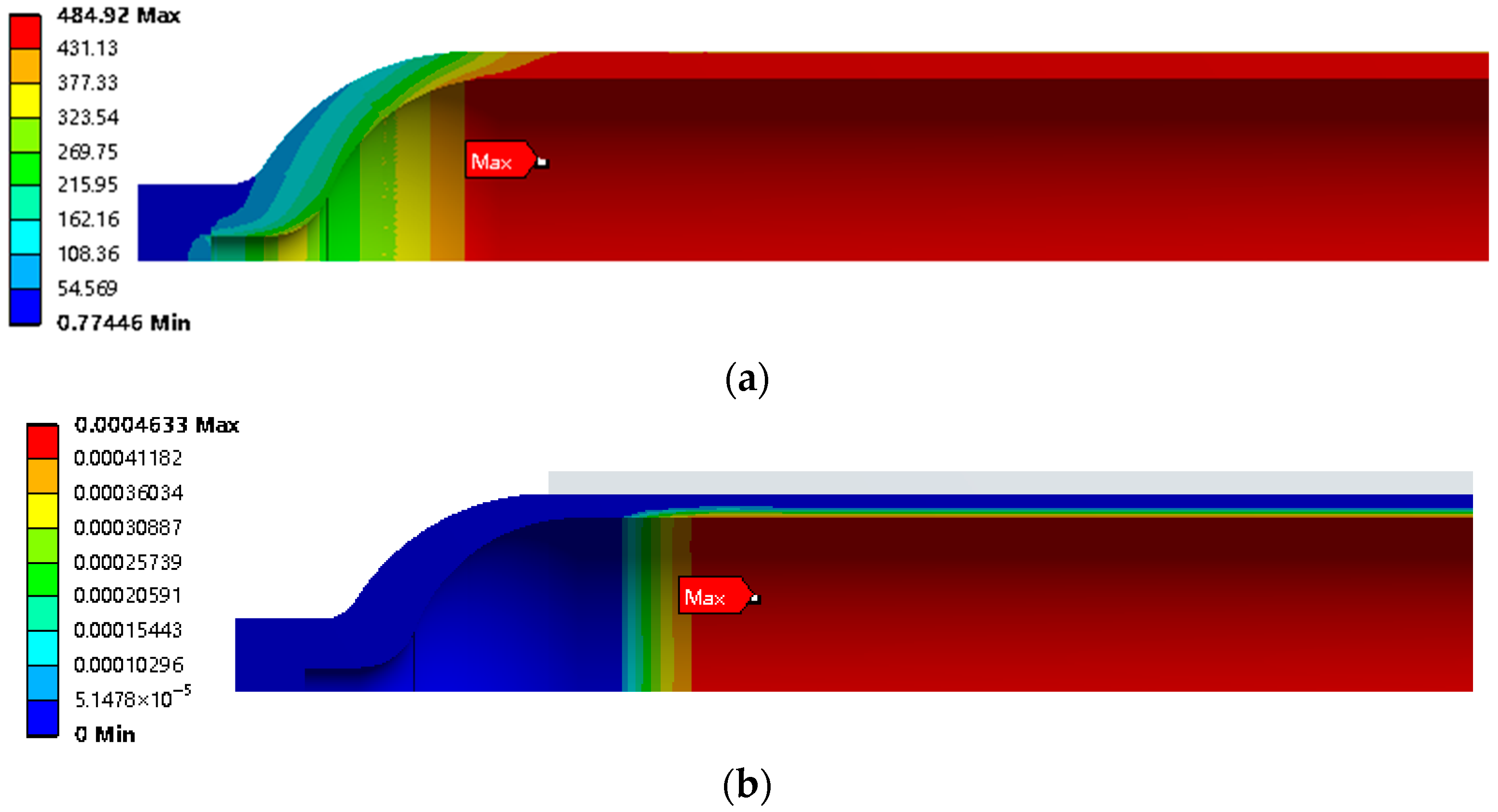
Figure 14 illustrates the stress and strain distribution within the Type II vessel under operating pressure. The liner attains its peak von Mises stress of 484.92 MPa, while the composite overwrap exhibits a maximum hoop stress of 295.44 MPa, both localized near the cylinder–head transition zone. This stress intensification primarily stems from diminished constraint due to reduced fiber winding coverage at the head geometry, coupled with bending moments generated at the structural discontinuity.
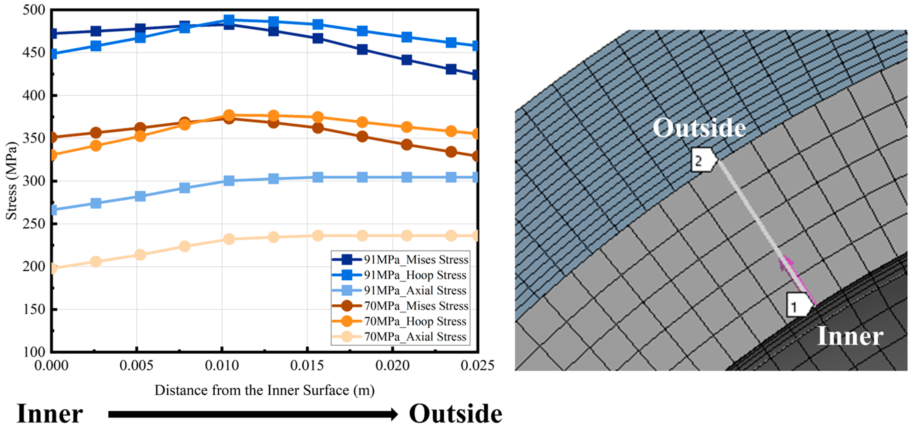
For Type II vessels, only the liner is exposed to hydrogen during service. Therefore, the inner wall surface in the middle of the liner cylinder is made along the wall thickness direction to the outer wall and the stress of the liner on the path is extracted, as shown in Figure 15.

3.4. Analysis of Leak-Before-Burst

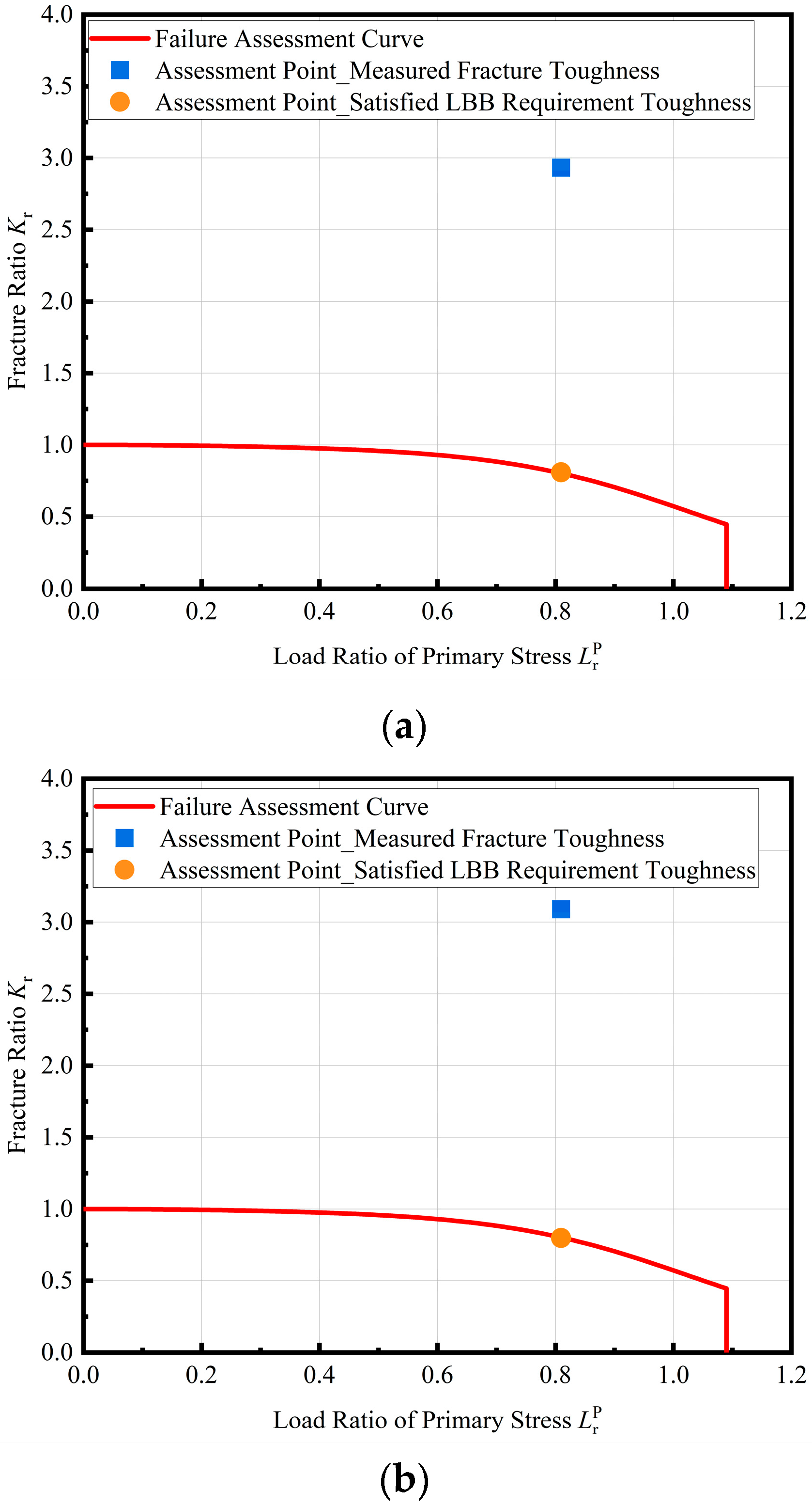
“Leak-before-burst” (LBB) denotes a critical failure mode wherein a through-thickness crack in a pressure vessel manifests as detectable leakage, not as catastrophic brittle fracture or plastic collapse, due to insufficient residual ligament strength. This controlled failure mechanism provides an essential warning for emergency response. In accordance with the requirements of ASME Section VIII Division 3 [34], in order to achieve LBB a vessel should meet the following conditions: (1) the crack, at a depth equal to 0.8 times the wall thickness, is shown to be below the critical flaw size when evaluated using the failure assessment diagram from API 579-1/ASME FFS-1; (2) the remaining ligament (distance from the crack tip to the free surface that the crack is approaching) is less than the quantity. For the vessel examined in this study, the LBB of the whole vessel should be determined by the LBB of the liner. According to condition (2), the fracture toughness required to meet this condition is 46.53 MPa·m0.5, which is slightly higher than the measured fracture toughness of 4130X in high-pressure hydrogen environments. At the same time, assuming that the crack depth is 0.8 times the thickness of the liner wall, the assessment point under the working pressure is calculated, as shown in Figure 16. At working pressure, the assessment point for a flaw depth of 0.8t (where t is the liner thickness) lies above the FAC when using the material’s actual fracture toughness. This placement indicates a failure to satisfy the LBB criterion, confirming that the Type II vessel studied cannot achieve LBB under current material properties and stress conditions. Further analysis reveals that achieving LBB compliance would require a prohibitively high fracture toughness of 178 MPa·m0.5, which is a value unattainable for Cr-Mo steels in high-pressure hydrogen environments.

3.5. Brittle Fracture Analysis at Working Pressure

Although the LBB criterion is not satisfied under the conservative assumption of a 0.8t flaw depth, this assessment represents a worst-case scenario. In operational practice, periodic non-destructive testing (NDT) ensures that actual flaws remain below detectable thresholds. Thus, the postulated flaw size should align with demonstrated NDT capabilities rather than standardized conservative values. According to the requirements of GB/T 44457-2024 [36] for seamless steel tubes, the groove depth of the used ultrasonic testing contrast sample should not be greater than 5% of the wall thickness of the steel tube, and not greater than 1 mm. Therefore, in this study the crack depth is assumed to be 1 mm.
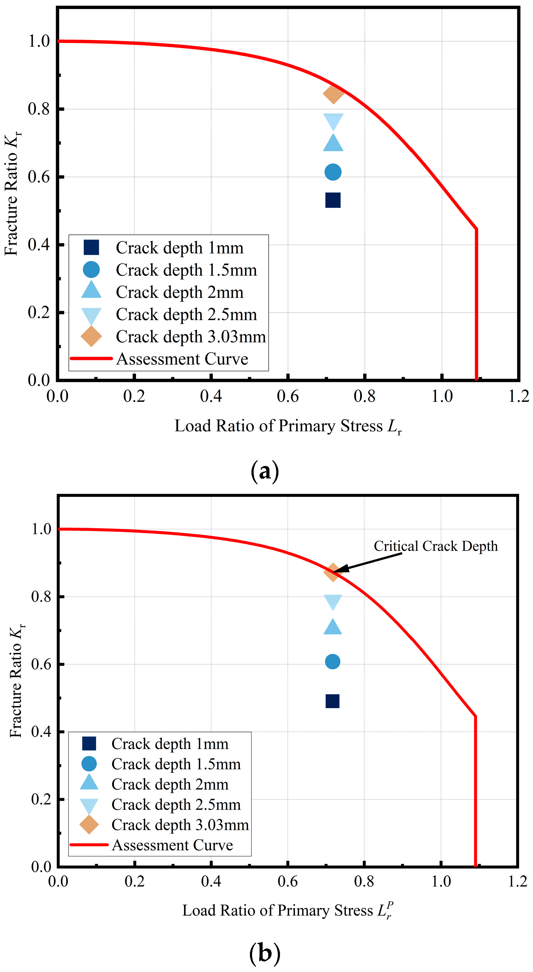
Based on the abovementioned crack hypothesis, the assessment results are shown in Figure 17. Under working pressure, when the fracture toughness of the Type II vessel studied is 46 MPa·m0.5 and the crack depth is 1 mm, the assessment point is located below the FAC and so the vessel is still in a safe state. A progressive increase in the postulated crack depth reveals the critical crack size for vessel failure. Figure 17 demonstrates that as the crack depth extends toward 3.03 mm (12.12% of the 25 mm liner thickness), the assessment point approaches the FAC. At this threshold, the stress intensity factor at the crack tip achieves criticality, triggering unstable fracture. Therefore, the critical crack depth of the studied Type II vessel is 3.03 mm.
In summary, when the fracture toughness of the liner material is 46 MPa·m0.5 for the Type II vessel studied, it cannot achieve the LBB failure mode. However, under working pressure, when the crack depth exceeds 3.03 mm the vessel fails, and the crack depth is greater than the minimum detectable crack size required by the standard. It can be concluded that for the Type II vessel studied, under the premise of ensuring the inspection of the vessel in accordance with GB/T 44457-2024, the cracks in the vessel can be detected before reaching a critical depth. Therefore, by establishing regular inspections of the vessel during service, it is possible to ensure that the vessel still continues to be used with cracks. However, as the vessel bears fatigue load, the cracks will further expand; therefore, how to determine a reasonable inspection period to avoid cracks reaching the critical depth before inspection needs to be considered according to the residual fatigue life of the cracked vessel.

3.6. Discussion on NDT Interval for Cracked Type II Vessel

The relationship between the number of fatigue cycles and the crack depth for the studied vessel is shown in Figure 18.
It is worth noting that employing Nc as the sole integrity metric provides zero safety margin for engineering practice. Therefore, in this study a more conservative design fatigue life Nd is used as an index. For the Type II vessel studied, the critical cycle number Nc is 2068 times, and the designed fatigue life Nd is 822 times. According to the expected fatigue condition of the vessel design, the fatigue cycle load is performed 11 times a day, and the design fatigue life of the vessel containing 1 mm is 74 days. Therefore, when the maximum crack depth detected in the vessel under study is 1 mm, the interval between the next detection and this detection should not exceed 74 days.
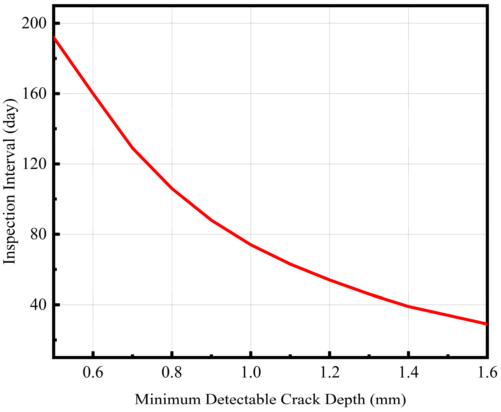
Even for the same vessel under the same working conditions, the inspection period between users will be different because of the difference in the minimum crack size that can be detected. Consequently, in this study, a defect tolerance design framework is established by calculating the residual fatigue life with the minimum detectable crack depth as the initial flaw size. The derived relationship between the minimum detectable crack depth and the required inspection interval quantified in Figure 19 enables optimized in-service maintenance planning for Type II vessels.
As shown in the figure, with the decrease in the ability of NDT to detect cracks the inspection cycle is significantly shortened, but with a further increase in the minimum crack depth that can be detected the shortening of the inspection cycle gradually decreases. For example, when the detectable minimum crack depth is increased from 0.5 mm to 1 mm, the inspection period is reduced from 192 days to 74 days, which is a reduction of 61.46%. When the minimum crack depth that can be detected is increased from 1 mm to 1.5 mm, the inspection period is reduced from 74 days to 34 days, which is a reduction of 54.05%. It can be concluded that the lower the defect detection ability of the NDT used, the more frequent the inspection of the vessel should be.
4. Conclusions

In view of the documented risks of brittle fracture and fatigue failure in high-pressure hydrogen environments for Cr-Mo steel, and recognizing a critical research gap in Type II vessel integrity, an FFS assessment was conducted on a prototype Type II hydrogen storage vessel. In situ mechanical testing under high-pressure hydrogen conditions was conducted and the mechanical property data for the liner material 4130X under hydrogen conditions was obtained. Concurrently, FEA was employed to determine stress distributions in the vessel under operational pressure and fatigue loading conditions. By integrating the hydrogen-degraded fracture properties with structural mechanical responses, a comprehensive FFS assessment was performed on the prototype vessel. The main conclusions are summarized as follows:
  • Through in situ testing under 100 MPa hydrogen, the 80.99% reduction in fracture toughness and nearly 100 times acceleration in fatigue crack growth rate of 4130X liner material was quantitatively characterized. Combined with the results of fracture morphology analysis, it is proved that the necessity of FFS assessment for Type II vessels. On this basis, an FFS assessment framework of Type II vessels considering the performance degradation of hydrogen-induced materials and the mechanical response behavior of complex structures was proposed, which filled the gap in the study of the structural integrity of Type II vessels under a high-pressure hydrogen environment.
  • The LBB assessment indicated that current 4130X material’s fracture toughness (46 MPa·m0.5) is far lower than required to satisfy the LBB condition requirement (178 MPa·m0.5). This finding reveals a critical material performance gap requiring mitigation through either material enhancement or operational condition adjustments.
  • The brittle fracture assessment confirmed vessel integrity at working pressure when crack depth remains below 3.03 mm. This critical size exceeds the threshold value of NDT detection capability (1 mm) required by the current standard, enabling a safety margin through periodic inspections. The residual fatigue life calculation (822 cycles at 1 mm crack depth) provides a quantitative basis for establishing inspection intervals.
Although this paper confirms the structural safety of the studied Type 2 vessel under certain conditions, the research conclusions also point out the inapplicability of the current inner liner material in the high-pressure hydrogen environment and the lack of FFS assessment methods unique to the Type II vessels. Therefore, it is believed that the follow-up research should focus on the following two aspects:
  • Developing hydrogen-resistant liner materials with improved fracture toughness.
  • Establishing hydrogen-specific FFS assessment methodology combining fatigue and fracture failure modes for Type II vessels.

Author Contributions

Conceptualization, H.H. and Z.C.; methodology, Z.C.; software, Z.C.; validation, S.H., Z.D., and G.X.; formal analysis, Z.C.; investigation, F.M.; resources, H.H.; data curation, S.H.; writing—original draft preparation, Z.C.; writing—review and editing, H.H.; visualization, Z.C.; supervision, H.H.; project administration, H.H.; funding acquisition, H.H. All authors have read and agreed to the published version of the manuscript.

Funding

This research was funded by the National Key Research and Development Program of China (2023YFB3408302), Science and Technology Planning Project of the State Administration for Market Regulation (No. 2024MK027) and National Natural Science Foundation of China (No. 52375143).

Data Availability Statement

Data is contained within the article.

Conflicts of Interest

The authors declare no conflicts of interest.

Abbreviations

The following abbreviations are used in this manuscript:
NDTNon-destructive testing
Type II vesselsHoop-wrapped vessels with metal liner
Cr-MoChromium–molybdenum
AISTAdvanced Industrial Science and Technology
CSEIChina Special Equipment Inspection and Testing Institute
FFSFitness-for-service
FADFailure assessment diagram
FEAFinite element analysis
SSRTSlow strain rate tensile
FCGRFatigue crack growth rate
CTCompact tension
MVCMicro-void coalescence
HELPHydrogen-enhanced localized plasticity
HEDEHydrogen-enhanced decohesion
LBBLeak-before-burst
FACFailure assessment curve
ASMEAmerican Society of Mechanical Engineers

References

  1. Hossain, M.M.; Siddique, B.Z. Hydrogen as an alternative fuel: A comprehensive review of challenges and opportunities in production, storage, and transportation. Int. J. Hydrogen Energy 2025, 102, 1026–1044. [Google Scholar] [CrossRef]
  2. Kumar, N.; Lee, S.Y.; Park, S.J. Advancements in hydrogen storage technologies: A comprehensive review of materials, methods, and economic policy. Nano Today 2024, 56, 102302. [Google Scholar] [CrossRef]
  3. Tahmasbi, M.; Siavashi, M.; Ahmadi, R. A comprehensive review of hydrogen production and storage methods: Fundamentals, advances, and SWOT analysis. Energy Convers. Manag. X 2025, 26, 101005. [Google Scholar] [CrossRef]
  4. Lu, X.; Krutoff, A.C.; Wappler, M.; Fischer, A. Key influencing factors on hydrogen storage and transportation costs: A systematic literature review. Int. J. Hydrogen Energy 2025, 105, 308–325. [Google Scholar] [CrossRef]
  5. Ahmad, S.; Ullah, A.; Samreen, A.; Qasim, M.; Nawaz, K.; Ahmad, W.; Alnaser, A.; Kannan, A.M.; Egilmez, M. Hydrogen production, storage, transportation and utilization for energy sector: A current status review. J. Energy Storage 2024, 101, 113733. [Google Scholar] [CrossRef]
  6. Hua, Z.; Gao, W.; Chi, S.; Wang, X.; Zheng, J. Development status and challenges of high-pressure gaseous hydrogen storage vessels and cylinders in China. Renew. Sustain. Energy Rev. 2025, 214, 115567. [Google Scholar] [CrossRef]
  7. Millenium, W.; Nabipour, A.H. Hydrogen Energy Storage System: Review on Recent Progress. Energy Eng. 2024, 122, 1–39. [Google Scholar] [CrossRef]
  8. Zhang, Z.; Ma, K.; Li, L.; Peng, W.; Zheng, J. Study on the quenching strategies for seamless hydrogen storage vessels made of Cr-Mo steel. Int. J. Hydrogen Energy. 2025, 124, 280–289. [Google Scholar] [CrossRef]
  9. Feki, I.; Shirinbayan, M.; Nouira, S.; Bi, R.T.; Maeso, J.-B.; Thomas, C.; Fitoussi, J. Composites in high-pressure hydrogen storage: A review of multiscale characterization and mechanical behavior. Compos. Part C Open Access 2025, 16, 100555. [Google Scholar] [CrossRef]
  10. Newhouse, N.L.; Rawls, G.B.; Rana, M.D.; Shelley, B.F.; Gorman, M.R. Development of ASME Section X Code Rules for High Pressure Composite Hydrogen Pressure Vessels with Nonload Sharing Liners. J. Press. Vessel Technol. 2012, 134, 030402. [Google Scholar] [CrossRef]
  11. ISO 14687: 2025; Hydrogen Fuel Quality—Product Specification. International Organization for Standardization: Geneva, Switzerland, 2025.
  12. Wang, Z.Y.; Han, L. Study on Performance Regeneration of Waste Solid Hydrogen Storage Material. Mar. Electr. Electron. Eng. 2025, 45, 18–22. [Google Scholar]
  13. Zhen, J.Y.; Ma, K.; Zhou, W.M.; Hu, J.; Gu, C.H.; Hua, Z.L. High-pressure Gaseous Hydrogen Storage Vessel for Hydrogen Refueling Station. Press. Vessel Technol. 2018, 35, 35–42. [Google Scholar]
  14. Li, X.L.; Hao, Y.M.; Wu, F.; Xing, Z.X.; Zhuang, S.Q.; Wang, X.Z. Numerical simulation of leakage jet flame hazard of high-pressure hydrogen storage bottle in open space. Int. J. Hydrogen Energy 2024, 62, 706–721. [Google Scholar] [CrossRef]
  15. Zheng, J.Y.; Liu, Z.L.; Hua, Z.L.; Gu, C.H.; Wang, G.; Chen, X.L.; Zhang, Y.W.; Zhu, S.Y.; Han, W.L. Research status-in-situ and key challenges in hydrogen safety. J. Saf. Environ. 2020, 20, 106–115. [Google Scholar] [CrossRef]
  16. Wang, X.J.; Xue, S.Y.; Dong, C.F. Research on Flow Behavior of 12Cr1MoV Steel under Conditon of Hot Compression Experiment. Hot Work. Technol. 2018, 47, 47–49. [Google Scholar]
  17. Huang, S.; Xue, G.K.; Hui, H.; Chen, Z.H.; Ru, X.K.; Sheng, X.; Ji, T.L.H.; Ding, Y. Mechanical property evolution of 4130X steel in high pressure hydrogen environment for hydrogen storage vessels. Press. Vessel Technol. 2024, 41, 8–15. [Google Scholar]
  18. Dadfarnia, M.; Martin, M.L.; Nagao, A.; Sofronis, P.; Robertson, I.M. Modeling hydrogen transport by dislocations. J. Mech. Phys. Solids 2015, 78, 511–525. [Google Scholar] [CrossRef]
  19. Iijima, T.; Itoga, H.; An, B.; San, M.C.; Somerday, B.P. Fracture Properties of a Cr-Mo Ferritic Steel in High-Pressure Gaseous Hydrogen. In Proceedings of the ASME 2015 Pressure Vessels and Piping Conference, Boston, MA, USA, 19–23 July 2015; American Society of Mechanical Engineers: New York, NY, USA, 2015. [Google Scholar]
  20. Gu, C.H.; Yao, Y.C.; Zhao, Y.M.; Ma, K.; Kuang, J.Y.; Zhang, R.M.; Liu, Y.Y.; Hua, Z.L.; Peng, W.Z. Experimental Study on Fracture Mechanical Properties of 4130X in 50MPa Hydrogen Environment. Light Ind. Mach. 2021, 39, 8–13. [Google Scholar]
  21. Zhang, X. Experimental Study on Hydrogen Embrittlement of 4130X for Application of High Pressure Hydrogen Storage and Safety Assessment of Crack Tolerance. Master’s Thesis, Zhejiang University, Hangzhou, China, 2016. [Google Scholar]
  22. Zhai, J.M.; Xu, T.; Wang, H.X.; Ma, G.Q.; Gui, L.L.; Shou, B.N. The hydrogen embrittlement sensitivity research of the hydrogen storage cylinder steel 4130X. China Spec. Equip. Saf. 2017, 33, 1–6, 26. [Google Scholar]
  23. Pan, S.P.; Gan, L. Evaluation of Pressure Vessels Subjected to Alternating Loads in Hydrogen Proximity and Analysis of the Causes of Defects. Chem. Mach. 2023, 50, 402–406. [Google Scholar]
  24. Qian, Z.W.; Bai, X.G.; Liu, W.; Kang, H.Y. Evaluation of the fit-for-use of high-pressure hydrogen storage tanks containing planar buried defects. China Spec. Equip. Saf. 2023, 39, 20–24. [Google Scholar]
  25. Wang, J.; Jia, X.; Ji, F.; Chen, Z.; Zhou, Y.; Ma, H.; Wang, K. Comparative analysis of calculation methods for fatigue crack growth life of hydrogen storage vessels. In Proceedings of the ASME 2023 Pressure Vessels & Piping Conference, Atlanta, GA, USA, 16–21 July 2023. [Google Scholar]
  26. Brown, R.G.; Buchheim, G.M.; Osage, D.A.; Janelle, J.L. Fitness for service evaluation of ring joint groove cracking. J. Press. Vessel Technol. 2000, 122, 72–75. [Google Scholar] [CrossRef]
  27. Esmaeely, S.N.; Prewitt, T.; Finneran, J.S. Feasibility Journey—Fitness for Service Assessment of Pipeline Materials in Repurposing Existing Natural Gas Pipelines to Transport Hydrogen—Natural Gas Blends. In Proceedings of the ASME 2024 Pressure Vessels & Piping Conference, Bellevue, WA, USA, 28 July–2 August 2024. [Google Scholar]
  28. Kappes, M.; Perez, A.T.E. Blending hydrogen in existing natural gas pipelines: Integrity consequences from a fitness for service perspective. J. Pipeline Sci. Eng. 2023, 3, 100141. [Google Scholar] [CrossRef]
  29. GB/T 228.1-2021; Metallic Materials-Tensile Testing Part 1: Method of Test at Room Temperature. Standardization Administration of the People’s Republic of China: Beijing, China, 2021.
  30. GB/T 21143-2014; Metallic Materials―Unified Method of Test for Determination of Quasistatic Fracture Toughness. Standardization Administration of the People’s Republic of China: Beijing, China, 2015.
  31. GB/T 6398-2017; Metallic Materials—Fatigue Testing—Fatigue Crack Growth Method. Standardization Administration of the People’s Republic of China: Beijing, China, 2017.
  32. Matsuo, T.; Yamabe, J.; Furukawa, H.; Seki, K.; Shimizu, K.; Watanabe, S.; Matsuoka, S. Development of New Strain Gage for High-Pressure Hydrogen Gas Use. Exp. Mech. 2014, 54, 431–442. [Google Scholar] [CrossRef]
  33. Somerday, B.P.; Campbell, J.A.; Lee, K.L.; Ronevich, J.A.; San, M.C. Enhancing safety of hydrogen containment components through materials testing under in-service conditions. Int. J. Hydrogen Energy 2017, 42, 7314–7321. [Google Scholar] [CrossRef]
  34. ASME SECTION VIII DIVISION 3; ASME Boiler and Pressure Vessel Code, Section VIII: Rules for Construction of Pressure Vessels, Division 3-Alternative Rules for Construction of High-Pressure Vessels. American Society of Mechanical Engineers: New York, NY, USA, 2019.
  35. API 579-1/ASME FFS-1; API 579-1/ASME FFS-1: Fitness-For-Service (FFS). American Petroleum Institute: Washington, DC, USA, 2021.
  36. GB/T 44457-2024; Hydrogen Storage Pressure Vessel Used in Hydrogen Refueling Station. Standardization Administration of the People’s Republic of China: Beijing, China, 2025.
  37. Zhang, R.M.; Ma, K.; Peng, W.Z.; Zheng, J.Y. Effects of hydrogen pressure on hydrogen-assisted fatigue crack growth of Cr-Mo steel. Theor. Appl. Fract. Mech. 2024, 129, 104202. [Google Scholar] [CrossRef]
  38. Djukic, M.B.; Bakic, G.M.; Sijacki, Z.; Sedmak, V.A.; Rajicic, B. The synergistic action and interplay of hydrogen embrittlement mechanisms in steels and iron: Localized plasticity and decohesion. Eng. Fract. Mech. 2019, 216, 106528. [Google Scholar] [CrossRef]
  39. Merson, E.D.; Poluyanov, V.A.; Merson, D.L.; Vinogradov, A.Y. About the Nature of Quasi-Cleavage in Low-Carbon Steel Embrittled with Hydrogen. Met. Sci. Heat. Treat. 2019, 61, 191–195. [Google Scholar] [CrossRef]
  40. Martin, M.L.; Connolly, M.J.; DelRio, F.W.; Slifka, A.J. Hydrogen embrittlement in ferritic steels. Appl. Phys. Rev. 2020, 7, 041301. [Google Scholar] [CrossRef]
Figure 1. Liner material 4130X: (a) original material; (b) microstructure.
Energies 18 04463 g001
Figure 2. Dimensions of specimens: (a) smooth rod tensile specimen; (b) 0.5T CT specimen; (c) 0.25T CT specimen.
Energies 18 04463 g002aEnergies 18 04463 g002b
Figure 3. Mechanical properties test system for high-pressure hydrogen environment materials.
Energies 18 04463 g003
Figure 4. Structure diagram of Type II vessel.
Energies 18 04463 g004
Figure 5. Grid division of Type II vessel.
Energies 18 04463 g005
Figure 6. Boundary condition setting: (a) boundary conditions of Type II vessel; (b) load step curve.
Energies 18 04463 g006
Figure 7. Surface semi-elliptical axial assumed crack model.
Energies 18 04463 g007
Figure 8. Procedure of fatigue life analysis.
Energies 18 04463 g008
Figure 9. Stress–strain curve of 4130X.
Energies 18 04463 g009
Figure 10. R-curve of 4130X in air environment.
Energies 18 04463 g010
Figure 11. The loading line displacement–load curve of 4130X in a 100 MPa hydrogen environment.
Energies 18 04463 g011
Figure 12. Fatigue crack growth rate and the stress intensity factor amplitude of 4130X in different environments.
Energies 18 04463 g012
Figure 13. Compared with the fracture morphology of the air and 100 MPa hydrogen environment, the hydrogen environment shows more obvious brittle fracture characteristics.
Energies 18 04463 g013
Figure 14. Stress and strain distribution of Type II vessel under working pressure: (a) equivalent stress of liner; (b) equivalent plastic strain of liner; and (c) circumferential stress of laminate layer.
Energies 18 04463 g014aEnergies 18 04463 g014b
Figure 15. Stress distribution along the wall thickness direction of the liner under different working conditions.
Energies 18 04463 g015
Figure 16. LBB analysis of Type II vessel at working pressure: (a) deepest position of crack tip; and (b) free surface of crack tip.
Energies 18 04463 g016
Figure 17. Brittle fracture assessment of Type II vessels under working pressure based on different crack depth assumptions: (a) deepest part of the crack; and (b) free surface of the crack.
Energies 18 04463 g017
Figure 18. Relationship between number of fatigue cycles and crack depth.
Energies 18 04463 g018
Figure 19. Relationship between minimum detectable crack depth and inspection interval.
Energies 18 04463 g019
Table 1. Chemical composition of the original material.
CMnSiPSCrMo
0.300.870.2890.0150.0011.010.21
Table 2. Mechanical properties of carbon-fiber-reinforced plastic laminate.
Mechanical PropertiesUnitLaminate
Longitudinal Young modulusGPa121
Transverse Young modulusGPa86
In-plane shear modulusGPa4.7
Major Poisson’s ratio-0.27
Minor Poisson’s ratio-0.4
Table 3. Tensile properties of 4130X in different environments.
Tensile PropertiesUnitAir100 MPa Hydrogen
Yield StrengthMPa641658
Tensile StrengthMPa774788
Elongation%15.686
Reduction in Area%35.0521.75
Table 4. Fracture toughness of 4130X in different environments.
EnvironmentFracture Toughness (MPa·m0.5)
Air242
100 MPa hydrogen46
Table 5. Comparison of fracture toughness of 4130X in high-pressure hydrogen environment.
Test Pressure (MPa)Fracture Toughness (MPa·m0.5)Data Source
10046This Study
10352[18]
53
9032[21]
Table 6. Paris formula parameters of 4130X in different environments.
EnvironmentStress Intensity Factor Amplitude ΔK (MPa·m0.5)Cm
air18~31.218.4528 × 10−112.1928
100 MPa hydrogen15.53~43.495.4979 × 10−103.0117
Table 7. Comparison of Paris formula parameters of 4130X in high-pressure hydrogen environment.
Test Pressure (MPa)Stress Intensity Factor Amplitude ΔK (MPa·m0.5)CmData Source
10015.53~43.495.4979 × 10−103.0117This Study
9014.7~358.32 × 10−113.32[18]
10017.1~482.65 × 10−92.1061[37]
Disclaimer/Publisher’s Note: The statements, opinions and data contained in all publications are solely those of the individual author(s) and contributor(s) and not of MDPI and/or the editor(s). MDPI and/or the editor(s) disclaim responsibility for any injury to people or property resulting from any ideas, methods, instructions or products referred to in the content.