1. Introduction
Amid the global transition toward cleaner energy systems, hydrogen’s advantage of zero emissions has led many countries to prioritize hydrogen industry development [
1,
2,
3]. Currently, the major constraint on scaling up the hydrogen industry is hydrogen storage and transportation [
4]. The current hydrogen storage methods include hydrogen compression storage through high pressure, hydrogen liquefaction storage through low temperature, and hydrogen storage through physical or chemical adsorption. High-pressure gaseous storage, the most widely deployed technology, offers low cost and operational convenience [
5]. High-pressure hydrogen storage vessels, the core components of high-pressure hydrogen storage technology, are predominantly manufactured by single-layer monolithic spinning or integral forging [
6,
7]. However, as hydrogen storage pressure increases, single-layer vessels face challenges including inhomogeneous cooling during the heat treatment of thick-walled sections [
8] and prohibitively difficult non-destructive testing (NDT) of the inner surface [
6]. Hoop-wrapped vessels with metal liners (hereinafter referred to as Type II vessels), featuring a metal liner overwrapped with a circumferentially wrapped fiber-reinforced plastic layer specifically on the cylindrical section to carry the circumferential load [
9], offer a solution. This design facilitates wall thickness reductions and weight savings. Consequently, it has not only found application in stationary hydrogen storage [
10] but also holds significant market potential for mobile storage systems. For Type II vessels, relevant standards such as ISO 14687 require high purity of hydrogen storage (e.g., ≥99.97% [
11]). Similarly, metallic hydride systems often necessitate high-purity hydrogen (≥99.99%) to prevent surface passivation and capacity loss [
12].
The metal material of the hydrogen storage vessel is prone to cracking due to hydrogen embrittlement, which eventually leads to brittle fracture [
13]. The brittle fracture of the hydrogen storage container not only destroys the integrity of the container structure, but also provides a leakage channel for high-pressure hydrogen, which eventually leads to catastrophic physical rupture and leakage accidents [
14]. Therefore, it is important to carry out the experiments on the mechanical properties of materials under a hydrogen environment, especially the fracture performance test. At present, domestic and foreign testing standards such as ISO 11114-4, AN-SI/CSA CHMC 1, and ASME VIII-3 KD-10 have been issued [
15].
For Type II vessels, chromium–molybdenum (Cr-Mo) steel is typically employed as the liner material. This high-strength steel offers good hardenability [
16], satisfying high-pressure operational requirements. However, its body-centered cubic lattice structure exhibits marked toughness deterioration in high-pressure hydrogen environments [
17]. Research institutions, for example, including Sandia National Laboratories [
18], Japan’s National Institute of Advanced Industrial Science and Technology (AIST) [
19], Zhejiang University [
20,
21], and the China Special Equipment Inspection and Testing Institute (CSEI) [
22], have conducted fracture toughness and fatigue crack growth rate tests on various Cr-Mo steel grades under high-pressure hydrogen environments. Experimental results demonstrate that Cr-Mo steel exhibits significantly reduced fracture toughness under high-pressure hydrogen, manifesting brittle embrittlement characteristics. Concurrently, fatigue crack growth rates in high-pressure hydrogen environments are substantially accelerated compared to ambient air conditions. Consequently, pre-existing flaws in Cr-Mo steel vessels may trigger low-stress brittle fracture or accelerated fatigue crack propagation in high-pressure hydrogen environments, critically compromising structural integrity. Furthermore, a series of pressure-cycle fatigue tests conducted by the CSEI on flawed Type II vessels revealed significantly reduced residual fatigue life compared to single-layer vessels under identical conditions. For instance, a tested Type II vessel containing 0.6 mm cracks exhibited merely 2600 cycles to failure—over an order of magnitude lower than the 15,000-cycle endurance of single-layer vessel with equivalent flaws. In summary, for the Type II vessels serving in a high-pressure hydrogen environment the toughness degradation caused by hydrogen embrittlement and the potential failure risk of its own structure make it difficult to ensure its structural safety in a high-pressure hydrogen environment. It is necessary to carry out a fitness-for-service (FFS) assessment to determine its safety under service conditions.
FFS assessment constitutes a quantitative engineering methodology that verifies structural reliability during component operation. This fracture-mechanics-based integrity evaluation focuses on flawed components, determining their continued operational viability against standardized acceptance criteria. So far, research has been conducted on the fitness-for-service assessment of the components working in hydrogen environments. Pan et al. [
23] performed a fitness-for-service assessment on a hydrogen buffer tank within a hydrogenation reactor containing buried defects, concluding that the replacement of the defective area was necessary. Qian et al. [
24] assessed the serviceability of a 13.5 MPa hydrogen storage spherical vessel with buried defects at a hydrogen production station and supported the continued service of the vessel with defects. Based on a failure assessment diagram (FAD), Wang et al. [
25] applied different standards to calculate the residual fatigue life of hydrogen storage vessels, explored the discrepancies between these standards, and proposed corresponding correction methods. Separately, Brown et al. [
26] performed an FFS assessment on a flange groove containing hydrogen-assisted cracking within a hydrogenation vessel, and they clarified the variation in the crack driving force with crack depth in the flange’s local high-stress region. Esmaeely et al. [
27] discussed the technical difficulties in the FFS assessments of existing natural gas pipelines for hydrogen transport. Kappes et al. [
28] quantified the effects of hydrogen blending for pipelines on critical failure loads and critical defect sizes through an FFS assessment.
Although the abovementioned studies involved FFS assessments of diverse hydrogen-related components, their research scope remains predominantly confined to low-pressure petrochemical infrastructure (e.g., pipelines and storage vessels). Such components typically operate under low hydrogen pressures and are fabricated from ferritic steels. This differs from high-pressure hydrogen storage vessels that need to work under high hydrogen pressure and are made from high-strength steel. The degradation of material properties caused by hydrogen between them is also different. Therefore, it is necessary to combine the material performance parameters to more closely reflect the actual situation when conducting the FFS assessment. Furthermore, due to the inherent structural complexity of Type II vessels, obtaining analytical stress solutions in the liner under mechanical constraint from the hoop-wrapped composite layer is difficult. This complexity fundamentally impedes accurate FFS assessment for high-pressure hydrogen storage applications. Consequently, current research on the integrity of hydrogen storage vessels remains predominantly focused on single-layer vessels, with critically insufficient assessment of Type II vessels. The absence of FFS assessment protocols for such vessels poses significant risks to in-service structural integrity assurance. Consequently, research on the integrity assessment of Type II vessels is imperative. Thus, in this study a methodological framework for the FFS assessment of these vessels is established.
In this study, a Type II vessel with Cr-Mo steel as the liner material was taken as the research object, and the risk of brittle fracture and fatigue failure under a high-pressure hydrogen environment was evaluated. The mechanical properties of Cr-Mo steel were obtained via a mechanical properties test. Based on the measured material mechanical properties, the stress distribution of the studied Type II vessels under various working conditions was obtained based on finite element analysis (FEA). The FAD method was used to assess the leak-before-burst and brittle fracture failure of the studied vessel. The residual fatigue life of the studied Type II vessel with cracks was further calculated, and the relationship between the defect detection ability and the detection cycle of the NDT was explored.
3. Results and Discussions
3.1. Material Characterization
3.1.1. SSRT Test
The stress–strain curves of 4130X in an air environment and a 100 MPa hydrogen environment obtained through the SSRT test are shown in
Figure 9. It can be seen in
Figure 8 that, for the 100 MPa hydrogen environment, the stress–strain curve contains the complete uniform plastic deformation stage as the curve in the air environment.
Table 3 lists the tensile properties of 4130X in air and high-pressure hydrogen environments. It can be seen in
Table 3 that the strength of 4130X only changes slightly in the high-pressure hydrogen environment. For the yield strength, 4130X in the 100 MPa hydrogen environment increased by 2.65% compared with the air environment. The tensile strength of 4130X in the 100 MPa hydrogen environment was 1.81% higher than that in the air environment. However, for the toughness index, there was a significant difference between the air environment and hydrogen environment. The elongation and reduction in area of 4130X decreased by 61.73% and 37.95%, respectively, in the 100 MPa hydrogen environment, which means that the 4130X exhibited no large plastic deformation during fracture in the high-pressure hydrogen environment and that its fracture mode was more inclined toward brittle fracture. Similar trends have also been observed in the study of Zhejiang University [
21], which proves that the data results obtained in this paper have a certain degree of reliability. Therefore, it can be seen that for 4130X the influence of the high-pressure hydrogen environment is mainly reflected in its toughness, with no obvious toughness impairment being observed.
3.1.2. Fracture Toughness Test
As per GB/T 21143-2014 [
30], the plane strain fracture toughness
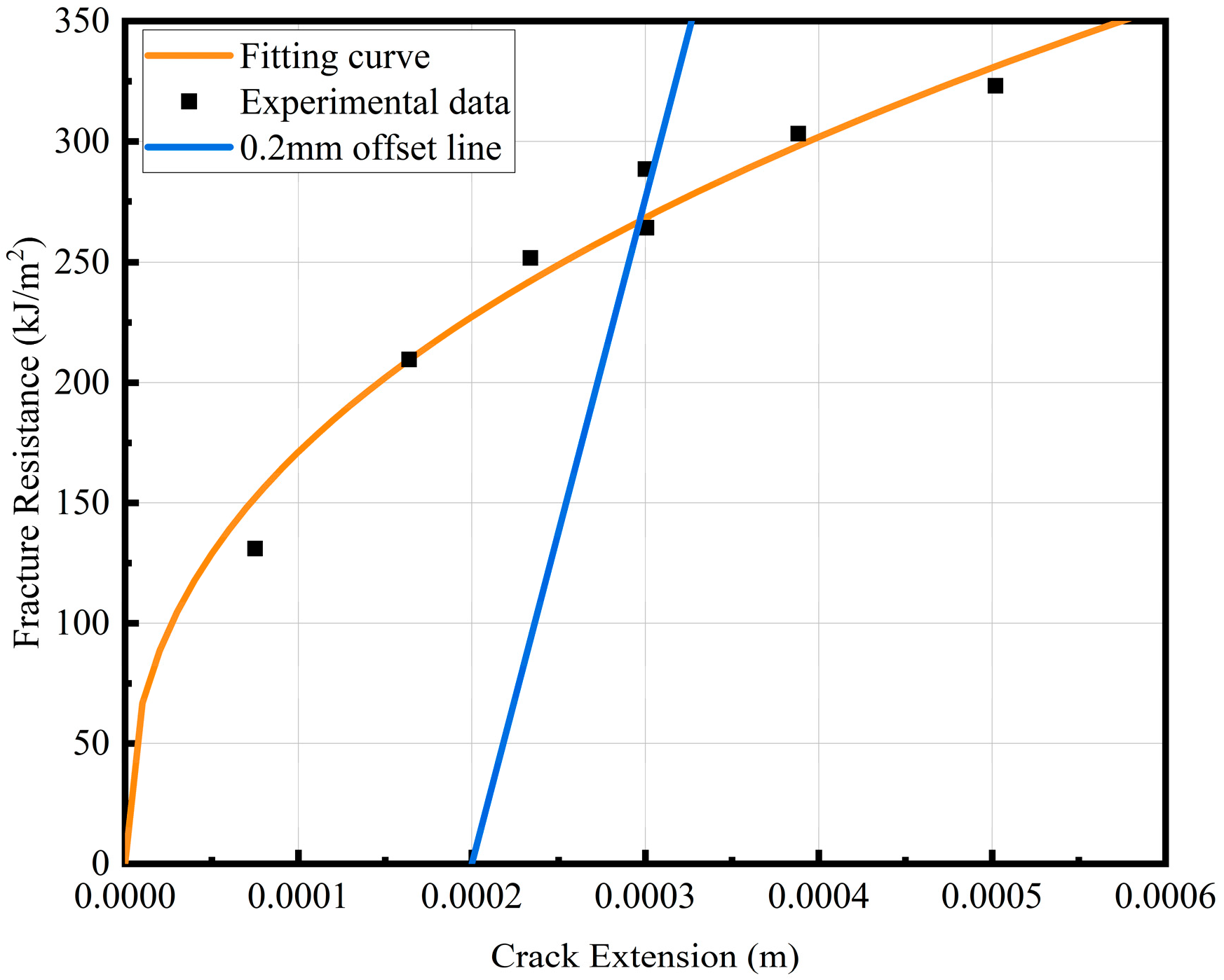
KIC of 4130X in air could not satisfy the validity criteria. Consequently, a multi-specimen resistance curve (R-curve) methodology was implemented to characterize crack growth resistance.
J0.2BL, which means the J integral corresponding to the crack stable propagation of 0.2 mm, is defined as the fracture initiation toughness to provide an equivalent fracture toughness metric when
KIC measurement is impractical. The
J0.2BL = 266 kJ/m
2 of 4130X in the air environment was calculated. According to the standard verification, the calculated
J0.2BL is effective and non-size sensitive. In order to facilitate the comparison with the fracture toughness of the 100 MPa hydrogen environment, Equation (10) was used to convert
J0.2BL into
KIC, where
E is the elastic modulus of material and
v is the Poisson ratio of material. The R-curve in air is shown in
Figure 10.
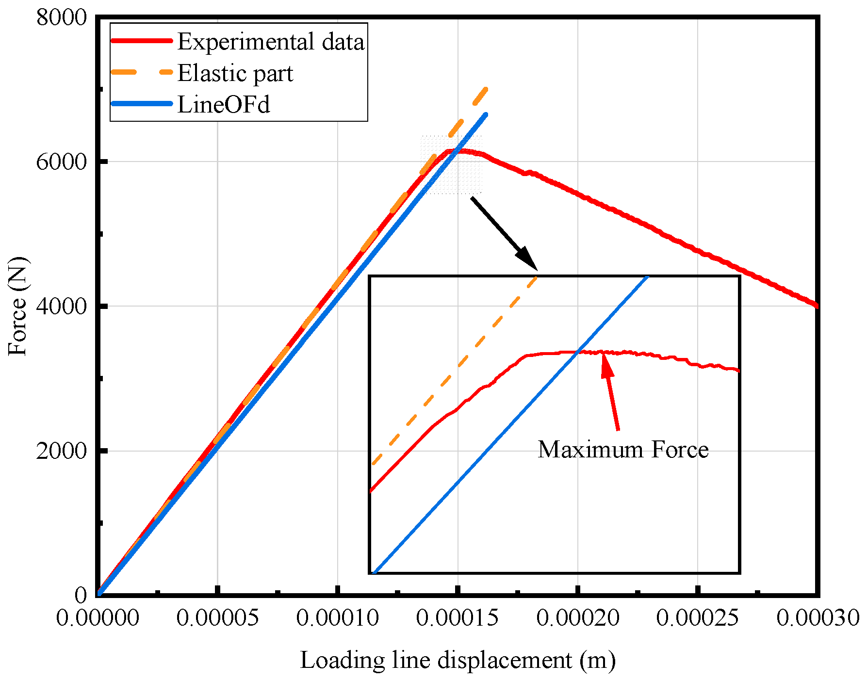
The loading line displacement–load curve of the fracture toughness test process in a 100 MPa hydrogen environment is shown in
Figure 11. The calculated
KIC is verified according to the requirements of GB/T 21143-2014 [
30]. The verification results show that the test results meet the validity requirements of plane strain fracture toughness. Therefore, the fracture toughness of 4130X in the 100 MPa hydrogen environment was calculated to be 46 MPa·m
0.5.
Table 4 summarizes the fracture toughness of 4130X under air and 100 MPa hydrogen environments. The data reveal a devastating 80.99% reduction in the fracture toughness of 4130X when exposed to a 100 MPa hydrogen environment. Crucially, the measured fracture toughness in the 100 MPa hydrogen environment is below the threshold of 50 MPa·m
0.5 stipulated in GB/T 44457-2014 [
36] for Cr-Mo steels operating at design pressure. The results fully illustrate the serious deterioration of the fracture toughness of 4130X under hydrogen conditions, demonstrating the risk of brittle fracture in high-pressure hydrogen environments.
Table 5 compares the fracture toughness of 4130X obtained in this study under a 100 MPa hydrogen environment with the data of 4130X under a similar environment reported in the literature. It can be seen that the difference between the 4130X obtained in this experiment and the data published in the literature is small. Therefore, it can be considered that the data obtained in this study has certain reliability. At the same time, by comparing with the data in the air environment, it can be seen that it is a common phenomenon that the fracture toughness of 4130X decreases significantly in the high-pressure hydrogen environment. Therefore, it is necessary to carry out FFS assessment for 4130X steel vessels serving in a high-pressure hydrogen environment.
3.1.3. FCGR Test
A series of standard 0.25T CT specimens with identical initial crack lengths were tested under different fatigue loads in the constant fatigue cycle, and the crack propagation length was recorded. The crack propagation velocity and average crack length of the different fatigue loads were calculated according to the secant method described in GB/T 6398-2017 [
31]. The obtained results were linearly fitted using a logarithm, and the Paris formula parameters
C and
m in the stable crack propagation stage were obtained. The relationship between the fatigue crack growth rate and the stress intensity factor amplitude Δ
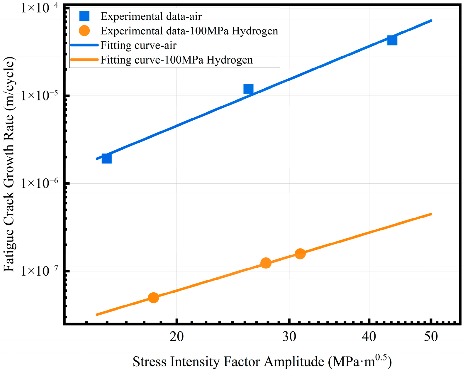
K of 4130X in an air and a 100 MPa hydrogen environment is shown in
Figure 12. The Paris formula parameters of 4130X in the air and hydrogen environments are listed in
Table 6. The fatigue crack growth rate of 4130X exhibits catastrophic acceleration in the high-pressure hydrogen environment, representing a two-orders-of-magnitude elevation in FCGR under the same Δ
K. This result proves that 4130X has a non-negligible risk of fatigue failure in hydrogen environments.
The data in this study are further compared with the published FCGR data of 4130X under high-pressure hydrogen environment. As shown in
Table 7, the FCGR of 4130X obtained in this study is lower than the data in the literature. Results show that even if it is 4130X, there are still some differences in FCGR under a high-pressure hydrogen environment. However, compared with the data in the air environment, the above results demonstrate that it is a common phenomenon that the FCGR of 4130X exhibits a significant acceleration trend in a high-pressure hydrogen environment, which means that the vessels manufactured by 4130X are more prone to fatigue failure in a high-pressure hydrogen environment. Therefore, it is necessary to predict its fatigue life and conduct regular NDT during service to avoid accidents.
3.2. Fractographic Analysis in High-Pressure Hydrogen
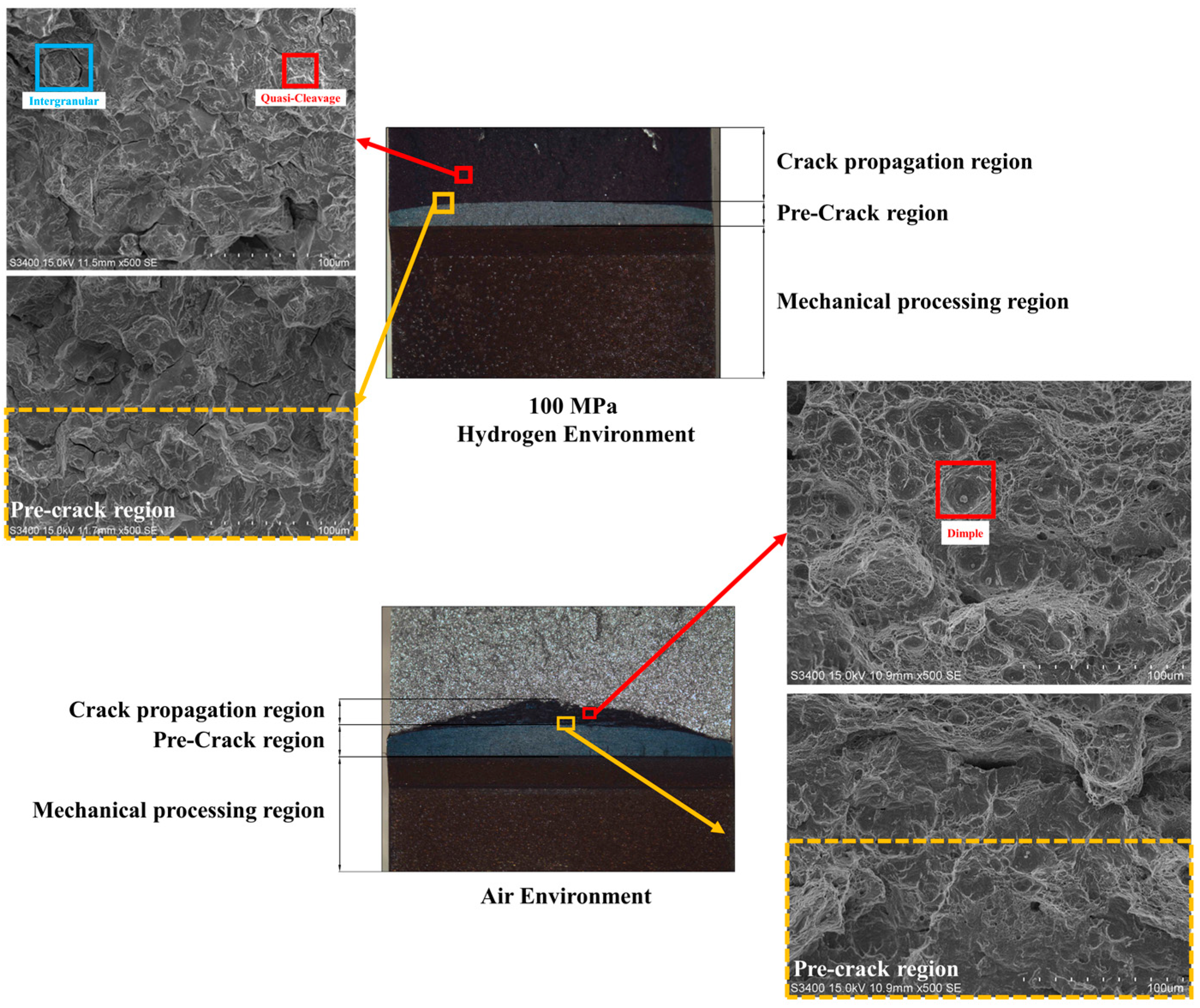
In a previous study, the hydrogen embrittlement sensitivity of 4130X in a high-pressure hydrogen environment was revealed by comparing the results of the mechanical properties test in different environments. The fracture surface of the fracture toughness specimen in air and 100 MPa hydrogen environments is shown in
Figure 13. The crack propagation of the specimen in air is less than that in the hydrogen environment. A fractographic analysis involving scanning electron microscopy revealed that the air-tested specimen exhibited a transition from a flat brittle fracture near the prefabricated crack tip to a micro-void coalescence (MVC)-dominated dimple fracture in the crack propagation region. Throughout the crack path, pronounced dimple tearing morphology was observed, confirming ductile failure mechanisms under ambient conditions. For the specimen tested in the 100 MPa hydrogen environment, a fractographic examination revealed cleavage river patterns at the prefabricated crack tip, while distinct inter-granular fracture features coupled with trans-granular cleavage characteristics dominated the subsequent crack propagation path. This fracture morphology arises from the synergistic interaction of multiple hydrogen embrittlement mechanisms in Cr-Mo steel. Current understanding attributes the hydrogen embrittlement mechanisms of Cr-Mo steel to the coupled mechanisms of hydrogen-enhanced localized plasticity (HELP) and hydrogen-enhanced decohesion (HEDE), as established in prior studies [
38,
39]. The HELP mechanism activates at low hydrogen concentrations, where it synergistically facilitates HEDE initiation. This coupling enables rapid crack nucleation at the pre-crack tip [
18,
40]. During subsequent propagation, direct HEDE activation occurs due to hydrogen accumulation at the advancing crack front, generating the observed inter-granular–trans-granular cleavage hybrid morphology.
In summary, the fracture analysis confirms that 4130X exhibits obvious brittle fracture behavior in high-pressure hydrogen environments. In order to ensure structural integrity, high-pressure hydrogen storage vessels made of 4130X should be applied for FFS assessment.
3.3. Results of FEA
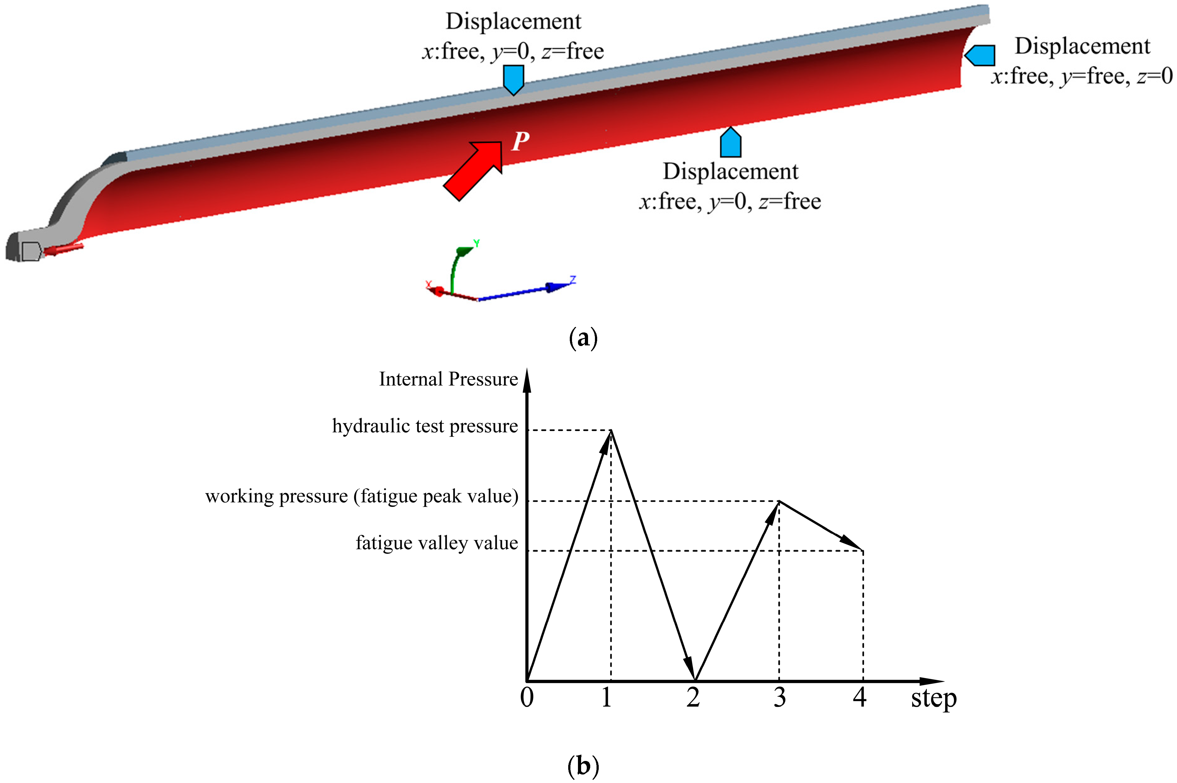
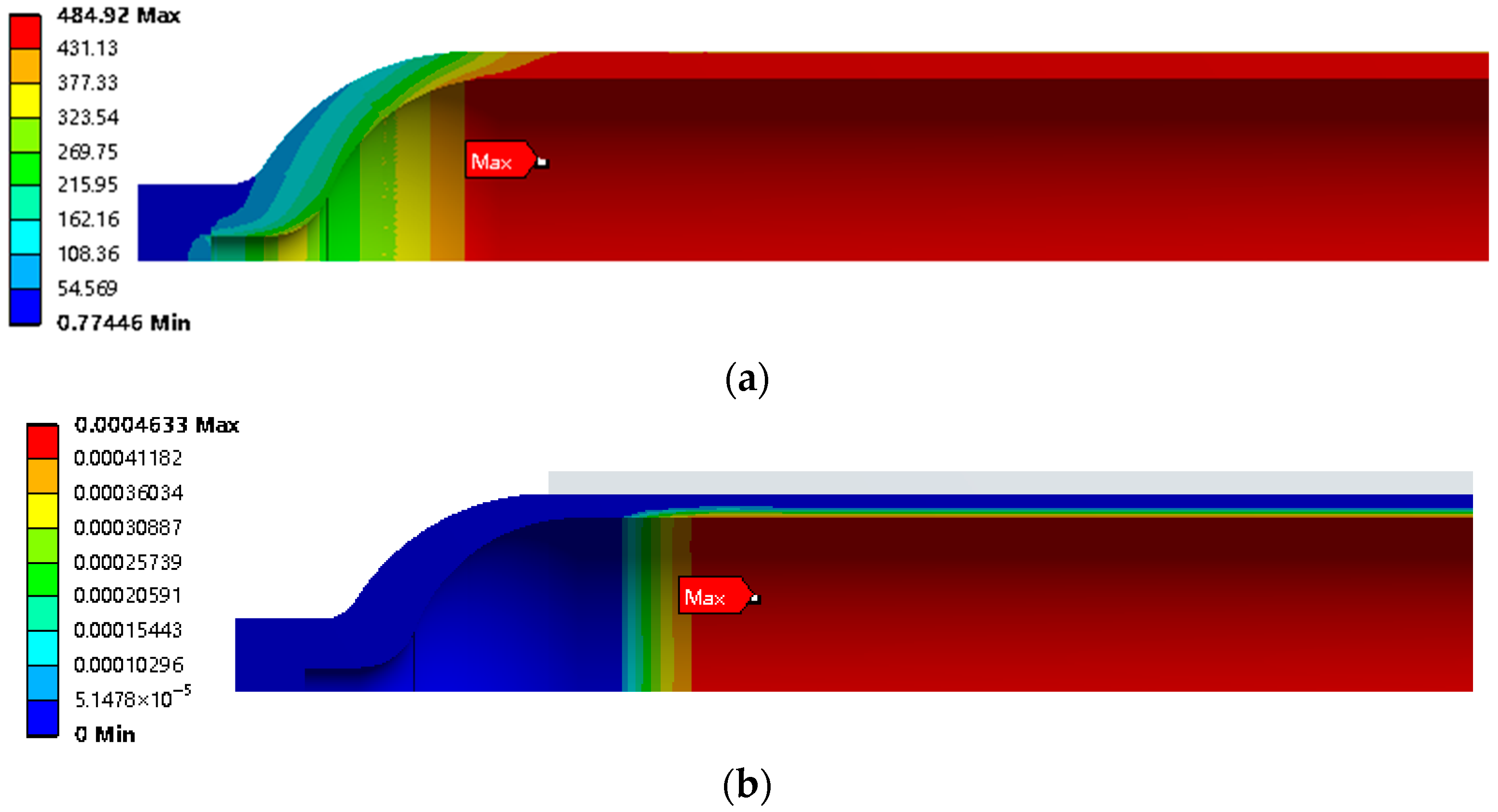
Figure 14 illustrates the stress and strain distribution within the Type II vessel under operating pressure. The liner attains its peak von Mises stress of 484.92 MPa, while the composite overwrap exhibits a maximum hoop stress of 295.44 MPa, both localized near the cylinder–head transition zone. This stress intensification primarily stems from diminished constraint due to reduced fiber winding coverage at the head geometry, coupled with bending moments generated at the structural discontinuity.
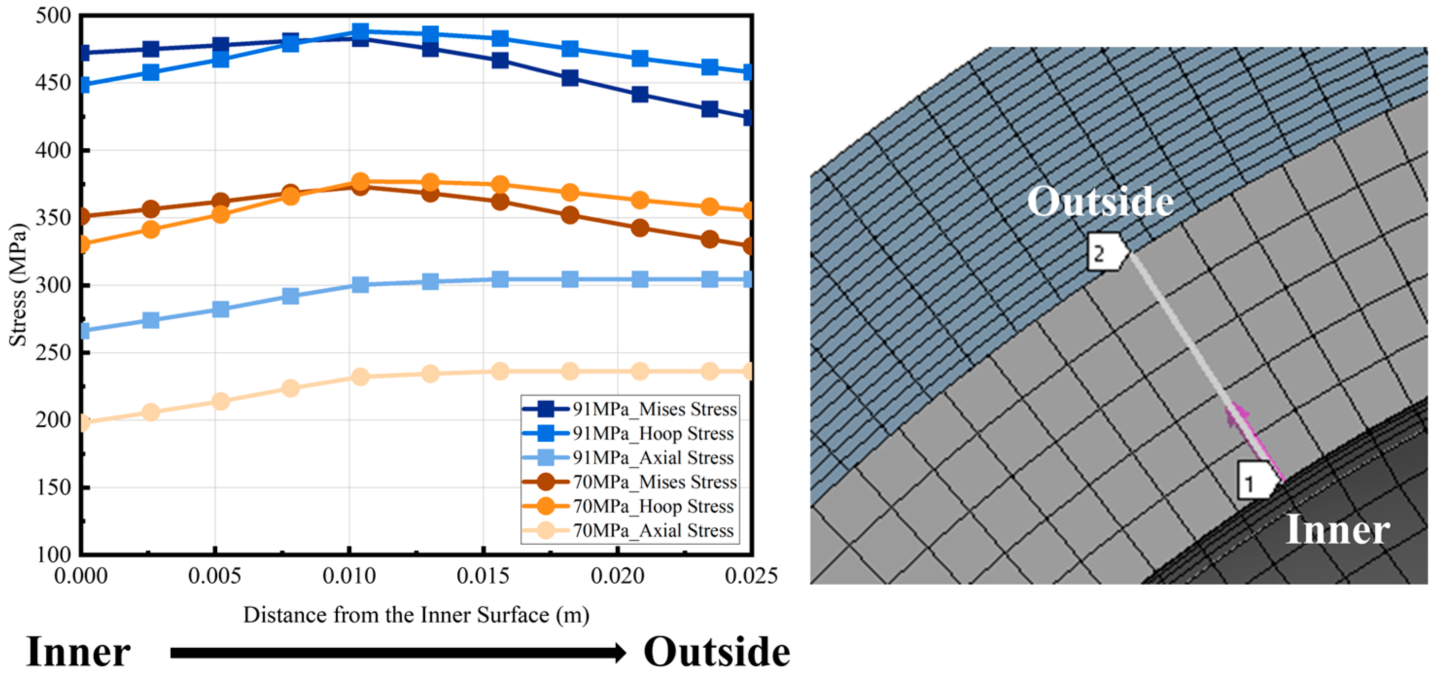
For Type II vessels, only the liner is exposed to hydrogen during service. Therefore, the inner wall surface in the middle of the liner cylinder is made along the wall thickness direction to the outer wall and the stress of the liner on the path is extracted, as shown in
Figure 15.
3.4. Analysis of Leak-Before-Burst
“Leak-before-burst” (LBB) denotes a critical failure mode wherein a through-thickness crack in a pressure vessel manifests as detectable leakage, not as catastrophic brittle fracture or plastic collapse, due to insufficient residual ligament strength. This controlled failure mechanism provides an essential warning for emergency response. In accordance with the requirements of ASME Section VIII Division 3 [
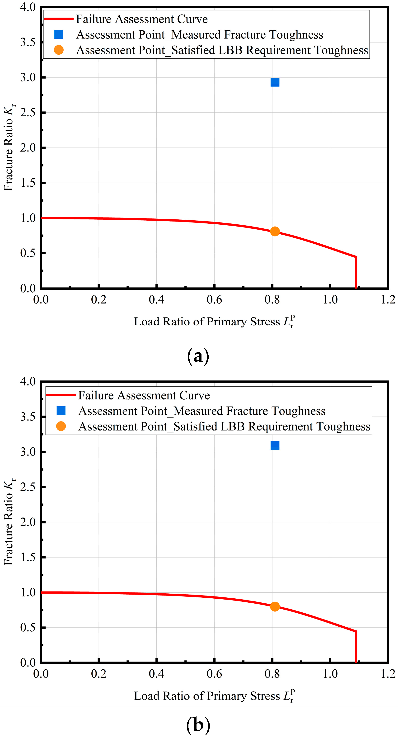
34], in order to achieve LBB a vessel should meet the following conditions: (1) the crack, at a depth equal to 0.8 times the wall thickness, is shown to be below the critical flaw size when evaluated using the failure assessment diagram from API 579-1/ASME FFS-1; (2) the remaining ligament (distance from the crack tip to the free surface that the crack is approaching) is less than the quantity. For the vessel examined in this study, the LBB of the whole vessel should be determined by the LBB of the liner. According to condition (2), the fracture toughness required to meet this condition is 46.53 MPa·m
0.5, which is slightly higher than the measured fracture toughness of 4130X in high-pressure hydrogen environments. At the same time, assuming that the crack depth is 0.8 times the thickness of the liner wall, the assessment point under the working pressure is calculated, as shown in
Figure 16. At working pressure, the assessment point for a flaw depth of 0.8
t (where
t is the liner thickness) lies above the FAC when using the material’s actual fracture toughness. This placement indicates a failure to satisfy the LBB criterion, confirming that the Type II vessel studied cannot achieve LBB under current material properties and stress conditions. Further analysis reveals that achieving LBB compliance would require a prohibitively high fracture toughness of 178 MPa·m
0.5, which is a value unattainable for Cr-Mo steels in high-pressure hydrogen environments.
3.5. Brittle Fracture Analysis at Working Pressure
Although the LBB criterion is not satisfied under the conservative assumption of a 0.8t flaw depth, this assessment represents a worst-case scenario. In operational practice, periodic non-destructive testing (NDT) ensures that actual flaws remain below detectable thresholds. Thus, the postulated flaw size should align with demonstrated NDT capabilities rather than standardized conservative values. According to the requirements of GB/T 44457-2024 [
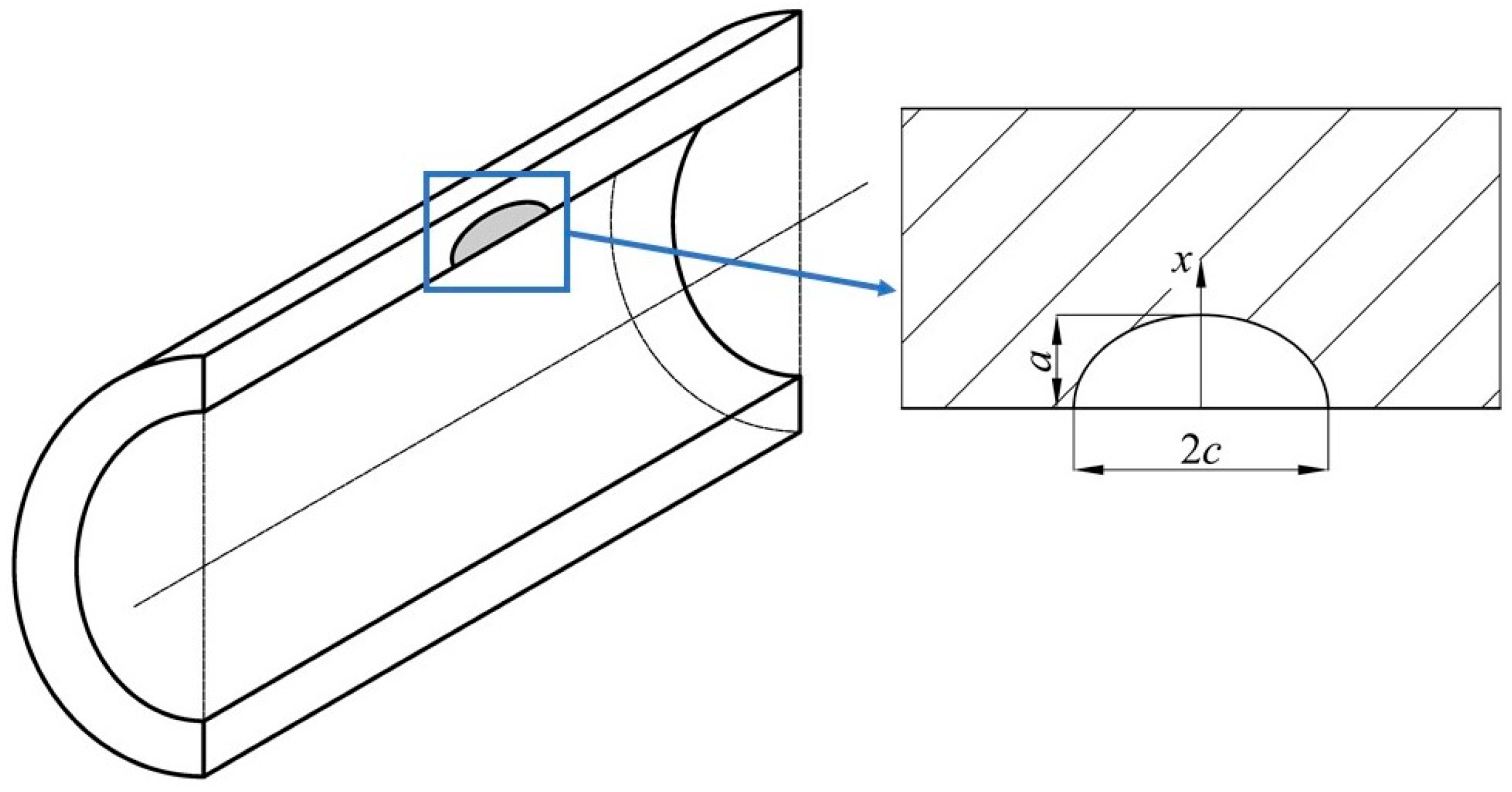
36] for seamless steel tubes, the groove depth of the used ultrasonic testing contrast sample should not be greater than 5% of the wall thickness of the steel tube, and not greater than 1 mm. Therefore, in this study the crack depth is assumed to be 1 mm.
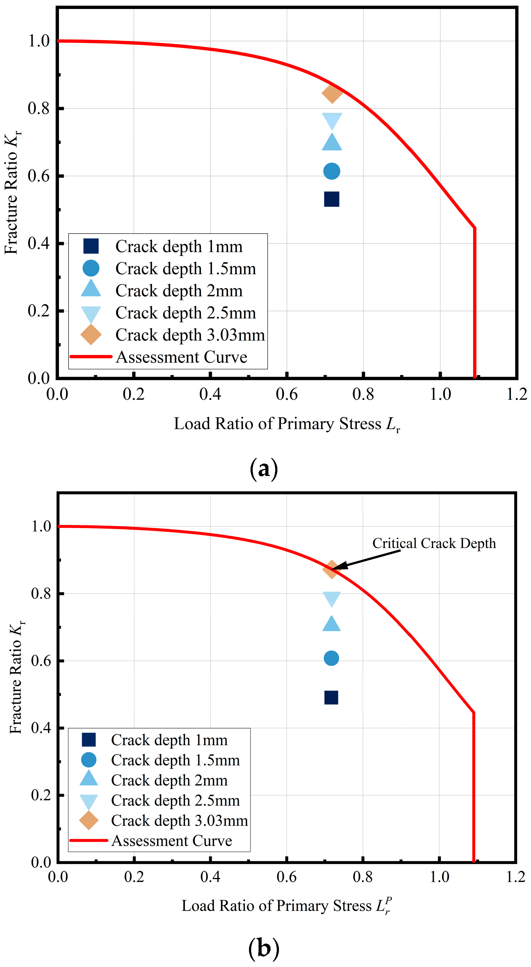
Based on the abovementioned crack hypothesis, the assessment results are shown in
Figure 17. Under working pressure, when the fracture toughness of the Type II vessel studied is 46 MPa·m0.5 and the crack depth is 1 mm, the assessment point is located below the FAC and so the vessel is still in a safe state. A progressive increase in the postulated crack depth reveals the critical crack size for vessel failure.
Figure 17 demonstrates that as the crack depth extends toward 3.03 mm (12.12% of the 25 mm liner thickness), the assessment point approaches the FAC. At this threshold, the stress intensity factor at the crack tip achieves criticality, triggering unstable fracture. Therefore, the critical crack depth of the studied Type II vessel is 3.03 mm.
In summary, when the fracture toughness of the liner material is 46 MPa·m0.5 for the Type II vessel studied, it cannot achieve the LBB failure mode. However, under working pressure, when the crack depth exceeds 3.03 mm the vessel fails, and the crack depth is greater than the minimum detectable crack size required by the standard. It can be concluded that for the Type II vessel studied, under the premise of ensuring the inspection of the vessel in accordance with GB/T 44457-2024, the cracks in the vessel can be detected before reaching a critical depth. Therefore, by establishing regular inspections of the vessel during service, it is possible to ensure that the vessel still continues to be used with cracks. However, as the vessel bears fatigue load, the cracks will further expand; therefore, how to determine a reasonable inspection period to avoid cracks reaching the critical depth before inspection needs to be considered according to the residual fatigue life of the cracked vessel.
3.6. Discussion on NDT Interval for Cracked Type II Vessel
The relationship between the number of fatigue cycles and the crack depth for the studied vessel is shown in
Figure 18.
It is worth noting that employing Nc as the sole integrity metric provides zero safety margin for engineering practice. Therefore, in this study a more conservative design fatigue life Nd is used as an index. For the Type II vessel studied, the critical cycle number Nc is 2068 times, and the designed fatigue life Nd is 822 times. According to the expected fatigue condition of the vessel design, the fatigue cycle load is performed 11 times a day, and the design fatigue life of the vessel containing 1 mm is 74 days. Therefore, when the maximum crack depth detected in the vessel under study is 1 mm, the interval between the next detection and this detection should not exceed 74 days.
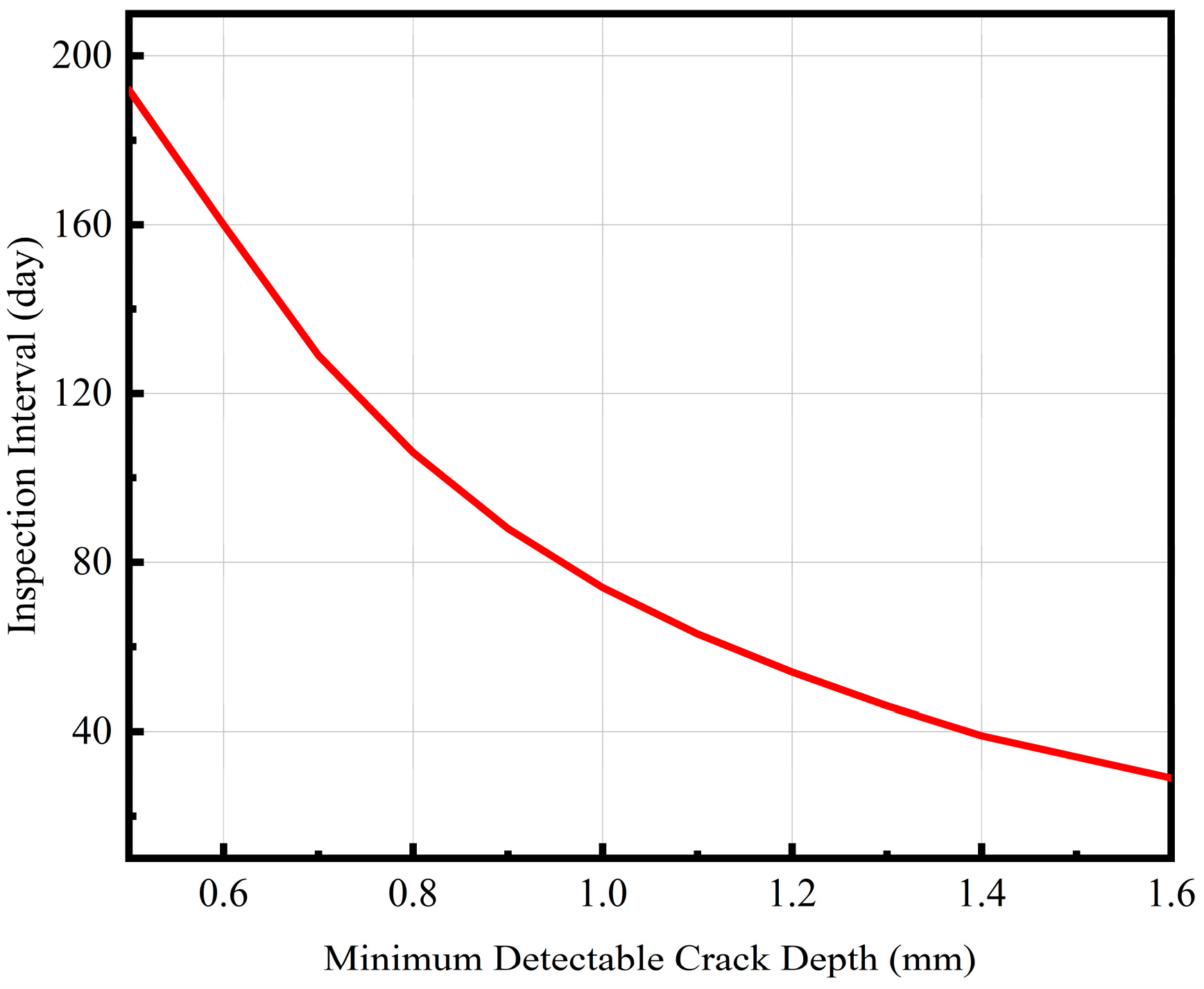
Even for the same vessel under the same working conditions, the inspection period between users will be different because of the difference in the minimum crack size that can be detected. Consequently, in this study, a defect tolerance design framework is established by calculating the residual fatigue life with the minimum detectable crack depth as the initial flaw size. The derived relationship between the minimum detectable crack depth and the required inspection interval quantified in
Figure 19 enables optimized in-service maintenance planning for Type II vessels.
As shown in the figure, with the decrease in the ability of NDT to detect cracks the inspection cycle is significantly shortened, but with a further increase in the minimum crack depth that can be detected the shortening of the inspection cycle gradually decreases. For example, when the detectable minimum crack depth is increased from 0.5 mm to 1 mm, the inspection period is reduced from 192 days to 74 days, which is a reduction of 61.46%. When the minimum crack depth that can be detected is increased from 1 mm to 1.5 mm, the inspection period is reduced from 74 days to 34 days, which is a reduction of 54.05%. It can be concluded that the lower the defect detection ability of the NDT used, the more frequent the inspection of the vessel should be.
