1. Introduction
Wireless power transfer (WPT) is an emerging technology that utilizes time-varying magnetic fields for energy transmission, offering advantages such as flexible charging, strong environmental adaptability, unplugging requirements, and enhanced charging safety [
1]. It has found widespread applications in rail transportation, medical devices, consumer electronics, and other fields [
2,
3,
4,
5,
6].
Rack-and-pinion modules are one of the most widely utilized transmission components in modern mechanical systems. They exhibit advantages such as cost-effectiveness, extended stroke lengths, and versatile mounting configurations, making them adaptable to diverse industrial requirements. Currently, these modules typically employ wired power supply systems, where electrical cables are enclosed within drag chains that reciprocate with the motor along linear guide rails. WPT technology can provide an efficient and convenient power delivery solution, effectively eliminating the limitations associated with tangled drag chains and environmental constraints [
7].
The kinematic characteristics of rack-and-pinion mechanisms inherently eliminate lateral misalignment between the transmitter and receiver coils during platform motion. To achieve compatibility with the extended stroke of linear guide rails, the transmitter coil is designed with equivalent longitudinal dimensions and positioned adjacent to the rack-and-pinion module. The receiver coil, rigidly fixed to the motor-driven moving platform, undergoes reciprocating linear motion synchronized with the platform. The significant disparity in coil lengths results in a weakly coupled state in the proposed WPT system [
8], leading to insufficient voltage and power delivery for motor operation. While increasing mutual inductance through larger coupling structures or higher coil turn counts can address these limitations, such methods inherently introduce issues including elevated material costs, increased winding and eddy current losses, and reduced installation flexibility.
To achieve cost efficiency, minimize coupling mechanism losses, and improve installation flexibility, a three-coil system incorporating a relay coil is introduced under the condition that the transmitter coil is designed as a single turn. Leveraging the mutual inductance enhancement effect of the relay coil, the system not only meets the output requirements of the load side but also maintains high efficiency under appropriately sized coupling mechanisms and reduced coil turn counts.
In non-radiative near-field WPT systems, the conceptual framework of relay coils was originally proposed by Rafif E. Hamam et al. [
9]. Existing studies have demonstrated that optimized design of relay coil parameters enhances system characteristics including misalignment tolerance [
10,
11], coil coupling strength [
12,
13], and operational efficiency [
14,
15,
16]. Furthermore, relay coils are widely adopted in long-distance wireless power transfer configurations to reinforce magnetic field coupling and elevate transmission power [
17,
18]. Diverse implementations of relay coils extend beyond singular configurations, with array-type coil architectures proving effective in redirecting energy flow paths [
19,
20].
Current investigations into three-coil compensation topologies reveal that relay coils exhibit enhanced performance under detuned conditions [
13,
21]. A fully detuned S-S-S topology proposed in reference [
13] achieves load-independent constant-current (CC) output and ZPA input characteristics. However, this theoretical framework neglects the impact of the inherent resistance of all three coils on the detuning frequency of the relay coil.
In medium- to long-distance WPT systems with relay coils, most studies systematically neglect cross-coupling between transmitter and receiver coils [
21,
22,
23,
24] while universally disregarding coil resistances in analytical models. Under the restrictive assumption of adjacent-coil coupling exclusivity, the fully resonant S-S-S topology in reference [
23] achieves load-independent CV output. Nevertheless, for coupling mechanisms with smaller air gaps, this method introduces a capacitive reactance component in the input impedance, thereby failing to achieve ZPA. Furthermore, it induces hard-switching operation in inverters, resulting in elevated switching losses. Existing studies predominantly adopt transmitter-side relay coil positioning [
21,
22,
23], a configuration incompatible with rack-and-pinion modules employing elongated transmitter rails.
This paper aims to eliminate the dragging chain structure by designing a stable and efficient WPT system for rack-and-pinion modules. The transmitter coil adopts a single-turn long-rail configuration, while the relay coil is fixed on one side of the receiving coil and performs linear motion with a mobile platform. Due to the close transmission distance, all cross-mutual inductances cannot be neglected in theoretical analysis. A fully detuned LCC-S-S compensation topology is employed to achieve both CV and ZPA while fully accounting for the influence of the inherent resistances of all three coils on detuning frequency selection. The reactance value of the relay coil not only affects the system’s output power and efficiency but also determines whether the rectifier bridge operates in CCM through its impact on compensation topology parameter calculation.
The main contributions of this paper are as follows:
- (1)
The proposed three-coil coupled structure utilizes the mutual inductance enhancement of the relay coil, with the transmitter coil designed as a single-turn long rail. The fully detuned LCC-S-S topology maintains CV and ZPA characteristics without neglecting any cross-mutual inductances or coil resistances. By adjusting the detuning frequency of the relay coil, the system’s output power and efficiency can be regulated as required.
- (2)
The selection of the relay coil’s detuning frequency affects the calculation of compensation topology parameters, thereby determining the rectifier’s CCM or DCM operation. This work derives the impact of the relay coil’s detuning frequency under fully detuned conditions on the critical transition condition between continuous and discontinuous modes of the rectifier bridge. Furthermore, the relay coil detuning frequency that maximizes system efficiency is selected under CCM operation.
The remainder of this paper is organized as follows:
Section 2 analyzes the proposed fully detuned LCC-S-S topology and demonstrates that the system exhibits CV and ZPA characteristics.
Section 3 equivalently transforms the three-coil topology into a traditional two-coil topology and theoretically analyzes how the detuned relay coil enhances the system’s mutual inductance. Since the reactance of the relay coil governs the compensation network parameter calculations,
Section 4 derives the current continuity condition of the rectifier bridge under the fully detuned LCC-S-S topology.
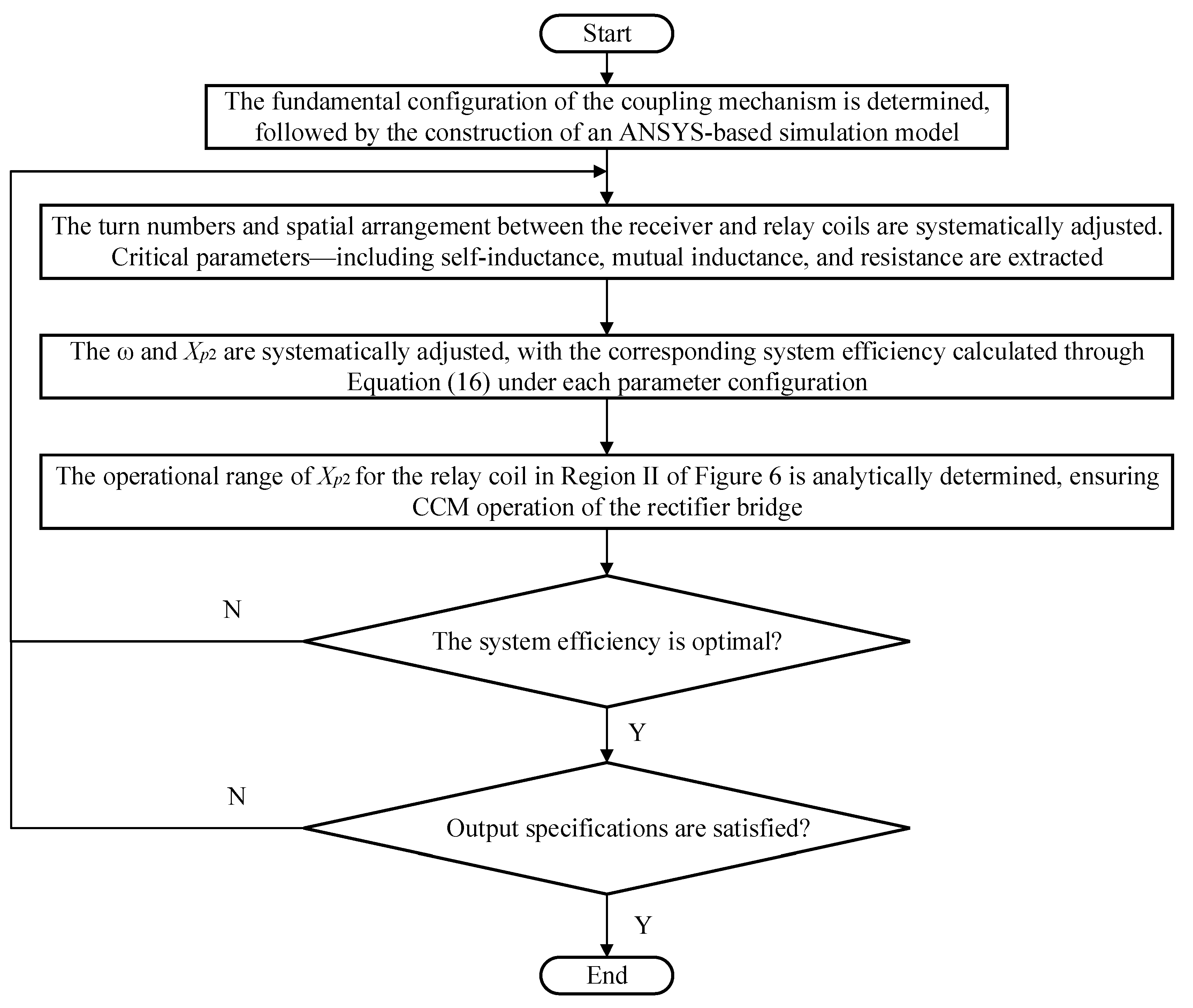
Section 5 presents the system optimization workflow and design parameters of the coupling structure.
Section 6 provides experimental results from the prototype and performs a loss analysis. Finally,
Section 7 concludes this paper. A flowchart of the article structure is presented in
Figure 1.
2. Analysis of the All-Detuned LCC-S-S Three-Coil Topology
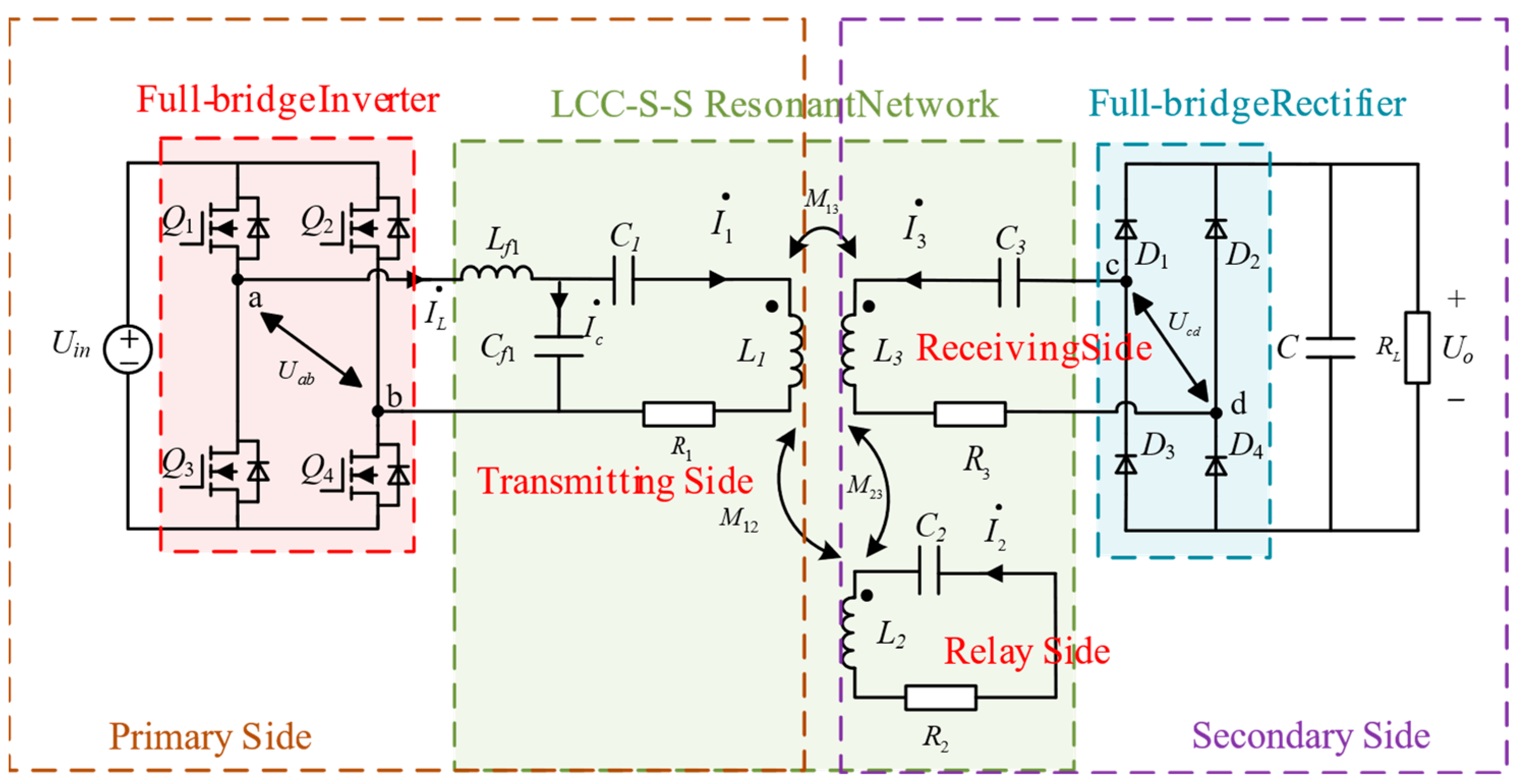
The overall structure of the proposed three-coil LCC-S-S compensated topology system is illustrated in
Figure 2. The primary side of the circuit is connected to a full-bridge high-frequency inverter, where
ω denotes the operating angular frequency of the inverter. The loosely coupled transformer comprises a transmitter coil (
L1), a relay coil (
L2), and a receiver coil (
L3), with
R1,
R2,
R3 representing their respective resistances. The mutual inductances
M12,
M13,
M23 correspond to the coupling between the transmitter and relay coils, transmitter and receiver coils, and relay and receiver coils, respectively. The resonant circuit of the relay coil is a passive LC resonant tank placed on the receiver side. The compensation network on the transmitter side includes
Lf1,
Cf1, and
C1, while the relay and receiver sides employ compensation capacitors
C2 and
C3, respectively. Notably, except for
Lf1 and
Cf1 on the transmitter side, which resonate at the switching frequency, all other inductive and capacitive loops are detuned from the switching frequency. Additionally, a full-bridge rectifier composed of diodes
D1~
D4 converts the alternating current (AC) in the resonant network into direct current (DC) for powering a DC servomotor load.
Owing to the filtering effect of the resonant circuit, the contribution of higher-order harmonics in the system can be considered negligible. Thus, the theoretical derivations focus solely on the fundamental component of the inverter’s output voltage. By applying the fundamental harmonic approximation (FHA) method, both the inverter and the rectifier bridge can be equivalently modeled as a linear sinusoidal voltage source and an equivalent input resistance, respectively. This equivalence linearizes the entire system, facilitating subsequent calculations. The relationship between the root mean square (RMS) value of the inverter’s output voltage and its DC input voltage is given in Equation (1). The rectifier and its subsequent resistance are equivalent to
Req shown in Equation (2), while the motor load’s equivalent internal resistance is
RL.
The overall circuit diagram is simplified using controlled-source equivalent models to represent the mutual coupling interactions between the three coils. The simplified circuit is illustrated in
Figure 3.
In
Figure 3, variables are defined in Equations (3)–(5).
By neglecting the internal resistances of the coils, Kirchhoff’s Voltage Law (KVL) is applied to each loop in
Figure 3.
The ratio of voltage
Ucd to voltage
Uab is shown in Equation (10).
When Equation (11) is satisfied, Equation (10) simplifies to Equation (12). The input-to-output voltage ratio becomes an expression independent of the load
RL, thereby validating the CV characteristic of the LCC-S-S topology.
Define Equations (13) and (14) as follows:
The equivalent input impedance is given in Equation (15). When the circuit topology and structural parameters of the coupling mechanism are determined, the imaginary part of the equivalent input impedance vanishes, theoretically verifying the ZPA characteristic of the circuit.
Meq is calculated by Equation (24).
The system efficiency can be calculated using Equation (16). The detuning frequency of the relay coil is directly related to the system efficiency. Therefore, it is essential to subsequently select an appropriate reactance value for the relay coil to achieve optimal efficiency.
3. Analysis of Mutual Inductance Enhancement in Relay Coils
To analyze the mutual inductance enhancement effect of the relay coil, the three-coil topology is equivalently modeled as a two-coil topology. Without neglecting the internal resistances of all coils, Kirchhoff’s voltage equations are formulated for the four loops in
Figure 3, yielding Equations (17)–(20).
By eliminating the current
I2 in the relay coil, Equations (21)–(23) are derived.
At this stage, the three-coil topology can be equivalently represented as a two-coil topology, where the expression for the equivalent mutual inductance is given by Equation (24). A schematic diagram of the equivalent two-coil topology is illustrated in
Figure 4.
Compared to the two-coil LCC-S topology, equivalent impedances
Z1p and
Z2p are added to the transmitter and receiver sides in
Figure 4, respectively. If the relay coil is fully resonant (
Xp2 = 0),
Z1p and
Z2p simplify to Equations (27) and (28). The denominators of
Z1p and
Z2p are solely the internal resistance
R2 of the relay coil, which introduces excessive resistance in the equivalent two-coil topology. This manifests as excessively high currents in the practical relay coil and significant losses in the system’s coupling mechanism. By properly detuning the resonance frequency of the relay coil, the current in the coils can be reduced while maintaining the required output voltage and power, thereby achieving higher system efficiency.
In this scenario, all three circuit loops are detuned relative to the switching frequency, yet the overall circuit operates in a resonant state with ZPA characteristics. The specific parameter calculation expressions for the circuit topology are given in Equations (29)–(33).
To account for the mutual inductance enhancement effect of the relay coil, transform Equation (34) as shown below:
where
q is expressed as
As shown in Equation (35), when q > 0 (i.e., Xp2 < 0), the equivalent mutual inductance Meq exceeds the mutual inductance M13 between the transmitter and receiver coils, indicating that the relay coil provides mutual inductance enhancement. Adjusting the detuning frequency of the relay coil (i.e., modifying Xp2) alters the mutual inductance enhancement factor, thereby regulating currents in all three coils and modifying both the coupling mechanism losses and system efficiency.
When the absolute value of Xp2 increases, the real parts of Z1p and Z2p decrease, which helps reduce system losses and improve constant-voltage characteristics. However, the mutual inductance amplification factor also diminishes under this condition, weakening the relay coil’s enhancement effect. This leads to higher current in the transmitter coil, thereby increasing system losses. In summary, an optimal Xp2 value exists to maximize system efficiency while maintaining robust CV performance.
4. Condition for CCM of the Rectifier in a Fully Detuned Topology
As derived from Equations (29)–(33), the compensation network parameters of the fully detuned LCC-S-S topology are inherently dependent on the detuning frequency of the relay coil. An improperly chosen Xp2 can force the rectifier bridge into DCM. Due to the nonlinear characteristics of diodes in the rectifier bridge, DCM operation introduces reactive power, causes waveform distortion in system currents, and degrades system efficiency. The peak receiver coil current during DCM operation is approximately 1.5 to 2 times that under CCM conditions. This elevated current at the receiver not only increases coupling mechanism losses but also raises the voltage stress on the receiver-side inductor and compensation capacitors, posing significant challenges for component selection.
The FHA method’s equivalence for the rectifier unit relies on the precondition of CCM operation. The equivalent input resistance of the rectifier under DCM deviates significantly from the ideal value defined by theoretical assumptions. Specifically, Equation (2) holds under two critical conditions: first, the rectifier input current operates in CCM, with its input voltage being a square wave of 50% duty cycle; second, the rectifier input current remains purely sinusoidal, devoid of higher-order harmonics. Violation of these conditions invalidates the FHA-based equivalence, leading to inaccurate system modeling and compromised power transfer efficiency.
Whether the rectifier input current operates in CCM is inherently dependent on the parameters of the resonant network. As derived from Equation (33), under fully detuned circuit conditions, the calculation of the receiver-side compensation capacitance involves multiple variables, including the receiver coil inductance
L3, system switching frequency
ω, mutual inductance
M23, and the reactance
Xp2 of the relay coil. In contrast, under resonant conditions, the compensation capacitance is determined solely by the switching frequency and coil inductance, with Equation (36) explicitly defining its value.
Under the fully detuned topology, the receiver-side compensation capacitance value is smaller than that under resonant conditions, resulting in a relatively larger capacitive reactance and higher capacitor voltage compared to the resonant state. This capacitor voltage superimposes on the output voltage, which may lead to discontinuous conduction in rectifier bridge. To maintain output stability and mitigate the adverse effects of high voltage stresses caused by discontinuous rectifier operation, it is critical to derive the current continuity condition for the rectifier bridge under the LCC-S-S fully detuned condition and select an appropriate reactance value for the relay coil under this condition.
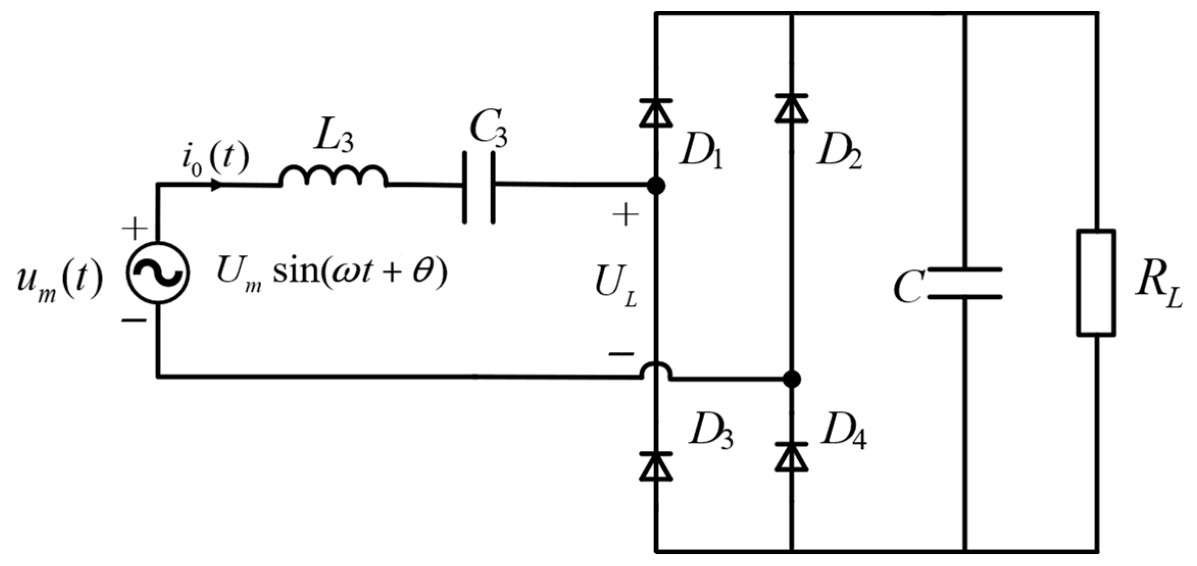
To derive the boundary conditions between discontinuous and continuous conduction of the rectifier bridge, an analysis of the simplified circuit in
Figure 5 is conducted. In this simplified circuit, the combined effect of the transmitting and relay coils on the receiver side is represented by a sinusoidal voltage source
Um(
t), where
θ is the initial phase of
Um(
t) and remains an unknown variable. When the capacitance paralleled with the load
RL is sufficiently large, the voltage ripple across the load
UL(
t) becomes negligible, allowing
UL(
t) to be approximated as a DC voltage
UL. The forward voltage drop of rectifier diodes is neglected in the derivation.
When the input current of the rectifier bridge transitions from negative to positive polarity, if the source voltage Um(t) is less than the load voltage UL, all four diodes remain in cutoff state. The rectifier bridge thereby enters DCM. The input current of the rectifier bridge will remain zero until source voltage Um(t) exceeds the load voltage UL. The boundary condition between CCM and DCM can be derived by analyzing the equivalent circuit in the Laplace domain under the given constraints.
Assuming that
i0 in
Figure 5 operates in CCM, the equivalent circuit configuration during the positive half-cycle of
i0 is illustrated in
Figure 6.
Formulating the circuit equations for the loop in
Figure 6 yields Equation (37).
The current calculation formula is given by Equation (38):
where
Applying partial fraction expansion, Equation (40) is obtained.
where
The time-domain expression of the current is given by Equation (44).
Applying Euler’s formula, Equation (44) is simplified to Equation (45).
Substituting Equation (39) yields the time-domain expression for the positive half-cycle of the current
i0(
t).
When
ωt = π, the current
i0(
t) becomes zero due to the symmetry between positive and negative half-cycles. This allows the derivation of Equation (47).
Since the capacitance paralleled with the load resistor is sufficiently large, the load voltage in steady state can be regarded as constant, implying that the net charge variation in the capacitor within one switching period is zero. Given that the output voltage ripple frequency after rectification is twice the switching frequency, it is sufficient to consider half a switching period. For the positive half-cycle of the rectifier bridge input current
i0(
t), the charge variation in the output capacitor is zero, meaning the average value of
i0(
t) equals the load current. This leads to Equation (48).
Simplifying Equation (48) yields Equation (49).
The simultaneous solution of Equation (47) and Equation (49) yields Equation (50).
When the rectifier bridge operates in CCM, the source voltage
Um(
t) must exceed the load voltage
UL at the critical moment when the input current
i0(
t) transitions from negative to positive polarity, thereby ensuring the continuity of
i0(
t). This condition necessitates compliance with Equation (51).
Substituting Equation (50) into Equation (51) yields Equation (52).
As indicated by Equation (52), the CCM and DCM states of the rectifier bridge are governed not only by the load resistance and receiver-side inductance but also by the self-resonant frequency of the receiving circuit. When the structural parameters of the coupling mechanism are fixed, the self-resonant frequency is primarily determined by
Xp2.
To analyze the impact of
Xp2 on the CCM and DCM boundary conditions of the rectifier bridge, Equations (54) and (55) are defined. Furthermore, as derived from Equation (52), the rectifier bridge operates in CCM when the condition
is satisfied.
When
Xp2 varies, the trends of
M(
Xp2) and
N(
Xp2) as functions of
Xp2 are as shown in
Figure 7.
As depicted in
Figure 7, the variation in
Xp2 can be divided into four distinct regions (Regions I to IV). In Regions I and III, the current continuity condition of the rectifier bridge is unsatisfied. In Region IV, the small absolute value of
Xp2 results in elevated system losses. Additionally, frequent waveform fluctuations observed in this section pose implementation challenges for subsequent hardware circuit design. Region II satisfies the current continuity condition of the rectifier bridge, and the absolute value of
Xp2 remains within an optimal range, facilitating both the identification of the system’s maximum efficiency point and the achievement of stable voltage regulation characteristics in the circuit topology. Therefore, the final value of
Xp2 should be selected from Region II.
6. Experimental Verification
An experimental validation platform was constructed on the QTW-series rack-and-pinion modular sliding platform, as illustrated in
Figure 10. The system architecture primarily comprises a DC power supply, a high-frequency inverter, a resonant compensation circuit, a coupling mechanism, a rectifier unit, and a DC servomotor. The detailed configuration of the experimental setup is explicitly depicted in
Figure 11a–d. To achieve lightweight and compact design objectives for the rack-and-pinion modular system, a DC motor with an integrated drive-motor assembly was selected, whose performance metrics are systematically documented in
Table 3.
The inverter is constructed using a full-bridge configuration comprising Infineon GS66508T GaN MOSFETs (Munich, Germany), while the rectifier employs a full-bridge topology with Dowo SP1560L Schottky diodes (Hangzhou, China). All self- and mutual-inductance values of the experimental prototype were measured using an RITUO TECHNOLOGY IM3570 impedance analyzer (Shenzhen, China).
Measurement waveforms were captured by a RIGOL MSO5104 oscilloscope (Beijing, China). Voltage and current parameters were acquired via Micsig DP3002 voltage probes (Shenzhen, China) and Micsig RCP300XS current probes (Shenzhen, China), respectively. System output voltage, current, and efficiency were quantified using a HIOKI PW8001 power analyzer (Nagano, Japan). The relevant system parameters are explicitly summarized in
Table 4.
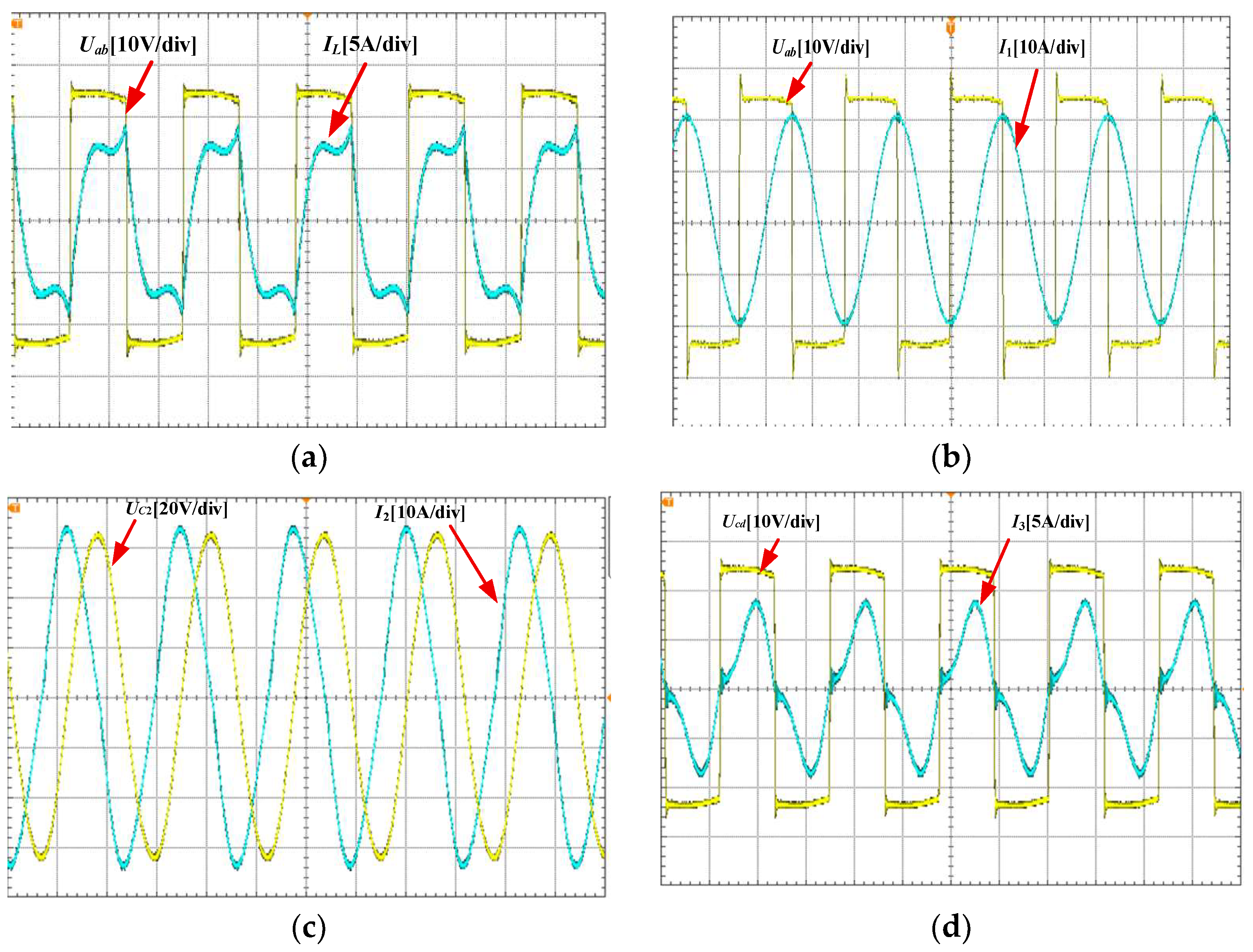
The inverter’s output voltage
Uab and current
IL are characterized in
Figure 12a. As the system’s output stage exhibits weakly inductive behavior with a minimal input impedance angle, ZVS is achieved in the inverter operation.
Figure 12b depicts the inverter output voltage
Uab and the transmitter coil current
I1, where
I1 manifests as a sinusoidal waveform with a peak amplitude of 21 A and maintains a 90° phase shift relative to
Uab. This phase relationship validates the resonant tuning of
Lf1 and
Cf1 at the switching frequency. The voltage
UC2 and current
I2 across the relay coil’s resonance capacitor
C2 are presented in
Figure 12c, with measured peak values of 66 V and 34 A, respectively. The voltage
Ucd and current
I3, illustrated in
Figure 12d, confirm the absence of DCM at the rectifier input, thereby verifying the rationality of the system’s parameter design. This observation exhibits congruence between theoretical predictions and empirical observations. Under these operating conditions, the receiver coil current attains a maximum amplitude of 9 A.
The measurement results obtained from the power analyzer and the system loss distribution are illustrated in
Figure 13a and
Figure 13b, respectively.
As shown in
Figure 13b, the transmitting side accounts for the highest proportion of total losses at 31.56%, primarily caused by its substantially larger coil dimensions (1200 mm × 60 mm). Additionally, the transmitting side integrates three compensation components (
Lf1,
Cf1, and
C1), whereas only a single capacitor is employed in both the relay and receiving circuits.
The relay coil utilizes 0.05 mm × 3600-strand litz wire, enabling it to withstand peak currents of 34 A. This design achieves exceptional operational stability while maintaining an exceptionally low internal resistance of 3.15 mΩ. Additionally, the smaller dimensions of the relay coil (90 mm × 60 mm) further contribute to its lower loss. Consequently, relay-side losses contribute merely 17.33% to the total system losses.
The output current and voltage parameters satisfy the operational requirements of the DC servomotor load under these conditions. At this operational state, the DC–DC conversion efficiency of the system is measured as 90.865%.
The comparison of existing research and the proposed system is presented in
Table 5.
While this paper demonstrates improved cost-effectiveness and installation flexibility for long-track applications, certain limitation still exist, which are as follows:
- (1)
With the objective of maximizing efficiency, the experimental validation in this study was confined to scenarios where the rectifier bridge operates in CCM. Experimental investigations regarding DCM operation will be performed in subsequent research.
- (2)
Despite employing relay coils to enhance system coupling, this study did not adequately address potential thermal risks induced by high currents in relay components. Comprehensive thermal analysis and effective management strategies should be prioritized in future studies.


