Article

Sensorless Induction Motor Control Based on an Improved Full-Order State Observer

by
Qiuyue Xie
1,
Qiwei Xu
2,
Lingyan Luo
2,*,
Yuxiaoying Tu
2,3 and
Wuyu Song
3,*
1
College of Electrical & Information Engineering, Hunan Engineering University, Xiangtan 411104, China
2
State Key Laboratory of Power Transmission Equipment Technology, School of Electrical Engineering, Chongqing University, Chongqing 400044, China
3
School of Intelligent Manufacturing, Wenzhou Polytechnic, Wenzhou 325035, China
*
Authors to whom correspondence should be addressed.
Energies 2025, 18(16), 4374; https://doi.org/10.3390/en18164374 (registering DOI)
Submission received: 26 June 2025 / Revised: 2 August 2025 / Accepted: 11 August 2025 / Published: 17 August 2025
(This article belongs to the Special Issue Recent Advances in Control Algorithms for Fault-Tolerant PMSM Drives)

Abstract

To eliminate the dependence of the induction motor (IM) flux-oriented control system on position sensors, IM sensorless control based on a full-order state observer is studied in this paper. First, according to the IM rotor flux linkage models of current and voltage, the speed of the full-order state observer for IM and the solution for the feedback matrix are designed. Then, to simplify the expression of the feedback matrix and improve the stability of the observer for high-speed operation, a novel solving method of the feedback matrix by left-shifting the poles of the observer is proposed, and the terms containing rotor speed are simplified. On this basis, a speed estimation method based on the current error and Lyapunov theory is proposed. For low-speed operation, the feedback matrix parameter design method is proposed based on the stability conditions of d–q axis current error model. Finally, the feasibility and effectiveness of the proposed full-order state observer are verified by simulation and experiment. Since the improved full-order state observer can provide accurate speed feedback and rotor flux position for flux-oriented vector control systems, the IM drive system exhibits good steady-state and dynamic performance.

1. Introduction

Induction motors (IMs) generate induced current in the rotor through a rotating magnetic field created by the stator [1], which offers advantages such as a simple structure, sturdiness, and durability [2]. Compared to a permanent magnet synchronous motor, it eliminates the need for permanent magnet materials and has advantages in power density and economy [3]. Therefore, IMs have been widely used in various industrial applications, such as rail transit and electric vehicles [4]. In recent years, scholars have conducted extensive and in-depth research on IM control strategies, including constant voltage–frequency ratio control [5], flux-oriented control [6], direct torque control [7], and model predictive control [8]. The above control methods are all very mature and can achieve good steady-state and dynamic performance. Still, they all rely on position sensors such as incremental encoders or rotary transformers to measure the rotor position and speed. However, in harsh industrial environments such as under high-temperature, high-pressure, and strong-electromagnetic-radiation conditions, the measurement signals of position sensors are susceptible to interference [9]. To improve the reliability of IM drive systems in the event of position sensor failures, it is necessary to conduct in-depth research on sensorless control.
The direct calculation method solves unknown variables such as speed and magnetic flux by establishing and solving equations consisting of a mathematical model and sampled voltage and current [10]. This algorithm is simple and computationally efficient, but it involves open-loop speed estimation. Estimation error will be caused by parameter mismatches or external disturbances. Therefore, it is necessary to use a closed-loop observer to achieve the sensorless control of IMs.
The model reference adaptive system (MRAS) takes a model without unknown parameters as the reference model and a model with estimated parameters as the adjustable model. It uses the output error of the reference model and the adjustable model to design an appropriate adaptive law to adjust the unknown variables of the adjustable model [11]. When the output of the adjustable model is equal to that of the reference model, the parameters to be identified converge to the actual values, thus achieving the purpose of parameter identification. Proportional-integral operation is usually selected as an adaptive algorithm, but, due to the presence of pure integration in the voltage model, there may be issues with integration drift and initial values [12]. In [13], a linear neuron speed digital observer is adopted as the adaptive law, and the low-speed performance is improved. However, the linear neural network requires the deviation of speed as the input, but the deviation cannot be accurately calculated by the A/D sampling system.
Reference [14] applies the extended Kalman filter algorithm to estimate the IM’s speed, which has high observation accuracy. Due to insensitivity to parameters and noise, high observation accuracy and robustness can be achieved. However, the extended Kalman filter algorithm requires a large number of matrix operations and depends on the selection of the covariance matrix, which increases the difficulty of its application in digital controllers [15]. The sliding mode observer is also insensitive to IM parameters and sampling noise and has fast dynamic convergence performance [16]. However, due to the introduction of the symbol switching function, the system state exhibits discontinuity, and the evaluated value of speed exhibits oscillations [17]. In addition, some artificial intelligence methods, including neural networks, particle swarm optimization, and ant colony algorithms, have also been applied for sensorless control of IMs [18,19]. However, due to the large computational complexity and low sampling and computation frequency, the above artificial intelligence methods have rarely been used in microprocessor-based digital control systems.
The adaptive full-order state observer adopts the IM as a reference model and the state space model as an adjustable model [20]. The estimated stator current error and rotor flux linkage are used as inputs for the adaptive mechanism, and the speed is identified through adaptive adjustment. Since the reference model contains all the information about the motor, the adaptive full-order observer has the advantages of a simple structure and low computational complexity and has reduced dependence on motor parameters [21]. However, the expression of the feedback matrix is complex and contains rotor speed, requiring real-time updates at each sampling period, which increases the computational complexity of DSP. Moreover, at high speeds, the observer has a large imaginary pole, which may lead to the instability of the observer.
In this paper, two different feedback matrix parameter design methods are proposed for low-speed and high-speed operating conditions. Meanwhile, a speed estimation method based on Lyapunov stability theory is proposed. This paper is organized as follows: The IM’s rotor flux linkage models of current and voltage are established in Section 2. The speed full-order state observer for IMs is designed in Section 3. The feedback matrix of the speed full-order state observer is improved, and a speed estimation method is proposed in Section 4. The feedback matrix design method for low-speed operation is proposed in Section 5. The simulation and experimental verifications are conducted in Section 6 and Section 7, respectively. The conclusion is drawn in Section 8.

2. Rotor Flux Linkage Model of IM Described by Voltage and Current

In this paper, the IM is supplied by a voltage source inverter; the topology is shown in Figure 1, where udc and Cdc represent the DC-side voltage and capacitor, S1~S6 are the bridge.

2.1. Current-Based Rotor Flux Linkage Model of IM

Since most IMs have a squirrel-cage structure, the rotor voltage is zero. For the sake of facilitating description, the voltage equations of the IM are rewritten as follows [22]:
u s α = R s i s α + p ψ s α u s β = R s i s β + p ψ s β 0 = R r i r α + p ψ r α + ω r ψ r β 0 = R r i r β + p ψ r β ω r ψ r α
where ψ and ψ represent the stator flux linkage in αβ axes, ψ and ψ represent the rotor flux linkage in αβ axes, i and i represent the stator current in αβ axes, i and i represent the rotor current in αβ axes, u and u represent the stator voltage in αβ axes, respectively. Rs and Rr represent the stator and rotor resistances, ωr represents the rotor electrical angular frequency, and p represents the differential operator.
The magnetic flux linkage equation can be expressed as
ψ s α = L s i s α + L m i r α ψ s β = L s i s β + L m i r β ψ r α = L m i s α + L r i r α ψ r β = L m i s β + L r i r β
where Ls, Lm, and Lr represent the stator, excitation, and rotor inductances, respectively.
From the last two equations in (1), it follows that
i r α = 1 R r p ψ r α + ψ r β ω r i r β = 1 R r p ψ r β ψ r α ω r
Substituting (3) into the last two equations in Equation (2), the following equations can be derived:
ψ r α = 1 1 + p T r L m i s α T r ψ r β ω r ψ r β = 1 1 + p T r L m i s β + T r ψ r α ω r
where Tr is equal to Lr/Rr.
Equation (4) is the current-based model of the rotor flux linkage, which requires stator current and speed signals to obtain the rotor flux linkage. This structure is simple and has no integration link, but Tr may change when the IM’s temperature changes or the flux linkage saturates. Therefore, the current-based model of rotor flux linkage is only suitable for medium- and low-speed applications.

2.2. Voltage-Based Rotor Flux Linkage Model of IM

The following equations can be derived from the first two equations in (1):
ψ s α = u s α R s i s α d t ψ s β = u s β R s i s β d t
Substituting (5) into the first two equations in (2), the following equations can be derived:
i r α = 1 L m [ u s α R s i s α d t L s i s α ] i r β = 1 L m [ u s β R s i s β d t L s i s β ]
Substituting (6) into the last two equations in (7), the following equations can be derived:
ψ r α = L r L m u s α R s i s α d t σ L s i s α ψ r β = L r L m u s β R s i s β d t σ L s i s β
where σ represents the leakage coefficient and is equal to 1 L m 2 / L s L r .
Equation (7) is the voltage-based model of the rotor flux linkage. In this model, the rotor resistance is not involved. Consequently, it is less susceptible to the variations in motor parameters and has no need for a speed signal. However, due to a pure integration process, there are issues such as initial integration values and error accumulation. The voltage divider effect of stator resistance is significant at low speeds, which amplifies the impact of measurement errors and makes the observed flux linkage no longer accurate. Therefore, the voltage-based model of the rotor flux linkage is only applicable to the medium- and high-speed range.

3. Adaptive Full-Order State Observer for IM

The observers introduced in Section 2.1 and Section 2.2 share the advantages of simple structure and ease of implementation. However, they are highly susceptible to parameter variations and external disturbances, resulting in inadequate measurement accuracy. The primary reason for this issue is the lack of a feedback mechanism in the aforementioned observers, which prevents error correction. Therefore, it is necessary to introduce a feedback mechanism to improve measurement accuracy.

3.1. Principle of Full-Order State Observer

According to modern control theory [20], a linear time-invariant system can be described as
x ˙ = A x + B u , x 0 = x 0 , t 0 y = C x
The implementation of state feedback requires the system’s state variables. However, some states cannot be directly measured, necessitating state reconstruction. The system used to achieve this reconstruction is typically referred to as a state observer, and the reconstructed or estimated states are called observed states. If the order of the observer is equal to that of the original system, it is called a full-order state observer.
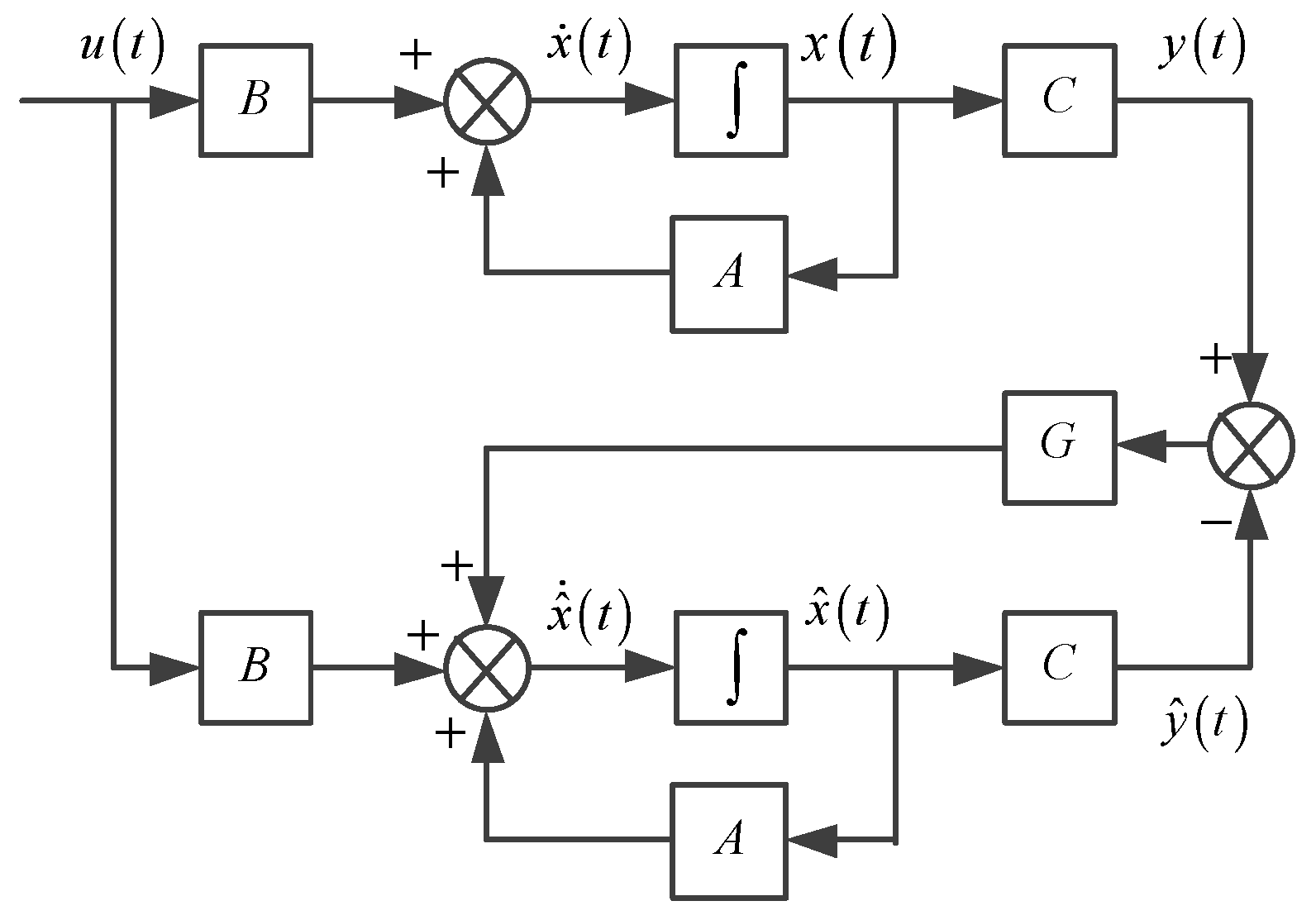
By multiplying the feedback matrix G with the difference between the actual system output y and the reconstructed output y ^ as a feedback term, a closed-loop system can be formed. With a properly selected feedback matrix, a full-order state observer for the given system can be constructed. The structure is shown in Figure 2, and its mathematical expression is
x ^ ˙ = A x ^ + B u + G y y ^ , x ^ 0 = x ^ 0

3.2. Full-Order State Observer for IM

From (4), the current-based model of the rotor flux linkage can be rewritten as follows:
d ψ r α d t = L m T r i s α 1 T r ψ r α ω r ψ r β d ψ r β d t = L m T r i s β + ω r ψ r α 1 T r ψ r β
From (7), the voltage-based model of the rotor flux linkage can be rewritten as follows:
d i s α d t = L m σ L s L r d ψ r α d t + 1 σ L s u s α R s σ L s i s α d i s β d t = L m σ L s L r d ψ r β d t + 1 σ L s u s β R s σ L s i s β
By substituting (10) into (11), the state equations of i and i can be expressed as
d i s α d t = 1 σ σ T r R s σ L s i s α + L m σ L s L r T r ψ r α + L m σ L s L r ω r ψ r β + 1 σ L s u s α d i s β d t = 1 σ σ T r R s σ L s i s β L m σ L s L r ω r ψ r α + L m σ L s L r T r ψ r β + 1 σ L s u s β
By combining (10) and (12) into a matrix form, the state-space equation of the IM can be obtained as follows:
d i s α d t d i s β d t d ψ r α d t d ψ r β d t = A i s α i s β ψ r α ψ r β + 1 σ L s 0 0 1 σ L s 0 0 0 0 u s α u s β y = 1 0 0 0 0 1 0 0 i s α i s β ψ r α ψ r β
where A is defined as
A = a 11 0 a 13 a 14 0 a 11 a 14 a 13 a 31 0 a 33 a 34 0 a 31 a 34 a 33 = a 11 I a 13 I a 14 J a 31 I a 33 I a 34 J       = 1 σ σ T r R s σ L s 0 L m σ L s L r T r L m σ L s L r ω r 0 1 σ σ T r R s σ L s L m σ L s L r ω r L m σ L s L r T r L m T r 0 1 T r ω r 0 L m T r ω r 1 T r
where I = 1 0 0 1 , J = 0 1 1 0 .
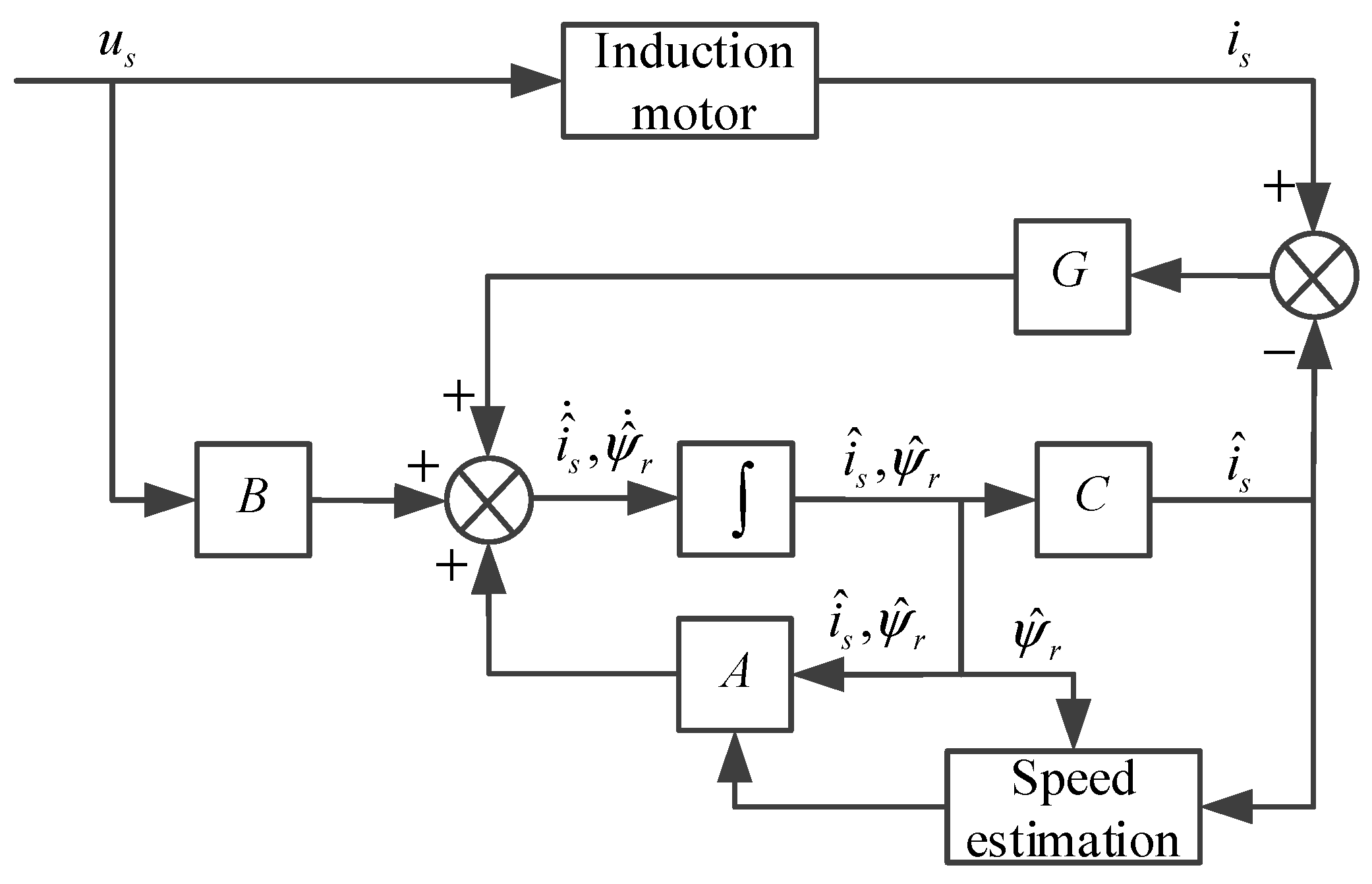
Furthermore, according to (9), the full-order state observer based on stator current error can be obtained, as shown in Figure 3. By adjusting the difference between the measured and estimated stator current, the rotor flux and rotor speed can be estimated. The variation in stator current indirectly reflects changes in rotor flux. When the measured and estimated stator currents are consistent, the estimated flux and speed can be considered equal to their actual values.

3.3. Solution for Feedback Matrix

Equation (9) can be modified as
x ^ ˙ = A G C x ^ + B u + G y
The differential of error e can be expressed as
d e d t = d d t x x ^ = A G C e
The convergence speed of e is determined by the pole positions of the matrix A G C . By designing the feedback matrix G reasonably, the matrix A G C can meet the dynamic requirements of the system, and the error is asymptotically stable and converges to zero as soon as possible. The feedback matrix G is usually set in the following form:
G = g 1 I + g 2 J g 3 I + g 4 J
At this time, the characteristic equation of the IM model is
f m s = s I A = s 2 I a 11 + a 33 I a 34 J s + a 11 a 33 a 31 a 13 I a 11 a 34 a 31 a 14 J
The characteristic equation of the observer model is
f o s = s I A G C = s 2 I a 11 g 1 + a 33 I a 34 + g 2 J s + a 11 g 1 a 33 g 2 a 34 a 13 a 31 g 3 + a 14 g 4 I a 11 g 1 a 34 + g 2 a 33 a 13 g 4 a 14 a 31 g 3 J
Due to the stability of the IM model, its poles are located in the left half of the plane. To ensure the stability of the observer, the poles of the observer can be placed to the left of the poles of the IM model. When a faster convergence speed can be obtained by the observer model, the ratio k between the poles of the observer and the poles of the motor model is set to k > 1. The following expression should be satisfied:
a 11 g 1 + a 33 I a 34 + g 2 J = k a 11 + a 33 I a 34 J a 11 g 1 a 33 g 2 a 34 a 13 a 31 g 3 + a 14 g 4 = k 2 a 11 a 33 a 31 a 13 a 11 g 1 a 34 + g 2 a 33 a 13 g 4 a 14 a 31 g 3 = k 2 a 11 a 34 a 31 a 14
By solving Equation (20), the values of g1, g2, g3, and g4 are obtained:
g 1 = k 1 1 σ T r + R s σ L s g 2 = 1 k ω r g 3 = k 2 1 1 σ L s T r + R s L r L m L m T r + 1 k L s T r + R s L r L m g 4 = k 1 σ L s L r L m ω r

4. Simplification for Feedback Matrix and Speed Estimation

4.1. Simplification for Feedback Matrix

According to (21), the expression of the feedback matrix is complex and contains rotor speed, requiring real-time updates at each sampling period, which increases the computational complexity of DSP. Moreover, at high speeds, the observer has a large imaginary pole, which may lead to the instability and poor dynamic performance of the observer. Therefore, this paper proposes a new method for solving the feedback matrix: shifting the poles of the observer by a constant distance b to the left relative to the poles of the IM, without changing the imaginary parts of the poles. Equation (20) is rewritten as
a 11 g 1 + a 33 I a 34 + g 2 J = a 11 + a 33 I a 34 J + 2 b a 11 g 1 a 33 g 2 a 34 a 13 a 31 g 3 + a 14 g 4 I a 11 g 1 a 34 + g 2 a 33 a 13 g 4 a 14 a 31 g 3 J = a 11 a 33 a 31 a 13 I a 11 a 34 a 31 a 14 J + b 2 b a 11 + a 33 I a 34 J
By solving Equation (22), the values of g1, g2, g3, and g4 are obtained:
g 1 = 2 b g 2 = 0 g 3 = σ L s L r 2 R r b + L m 2 R r 2 + L r 2 R r R s σ L s L r R r 2 σ L s L r 3 R r ω r 2 L m R r 2 + ω r 2 L r 2 b g 4 = σ L s L r 3 R r ω r b + L r L m 2 R r ω r + L r 3 R r R s ω r L m R r 2 + ω r 2 L r 2 b
It can be seen that Equation (23) still contains the rotational speed. If real-time updates are performed during operation, it will increase the computational burden. Here, a simplified method is proposed. Since the rotational speed is much greater than IM parameters, as ω r and simplifying (23), the values of g1, g2, g3, and g4 are obtained:
g 1 = 2 b g 2 = 0 g 3 = L s L r L m 2 R r L m b g 4 = 0
At this time, the feedback matrix is composed of constant values; it is easy to calculate and implement digitally.
Figure 4 shows the trajectory of the observer poles under different feedback matrices. When the feedback matrix is equal to zero, the main poles are very close to the imaginary axis. However, when the feedback matrix of (21) with k = 3 is introduced, the main poles are still close to the imaginary axis, and the imaginary part of the pole increases, which may lead to the instability and poor dynamic performance of the observer. When the poles of the observer shift to the left by 500 s−1, the imaginary part does not change, and the main poles are far from the imaginary axis, so the dynamic performance and the stability can be improved.
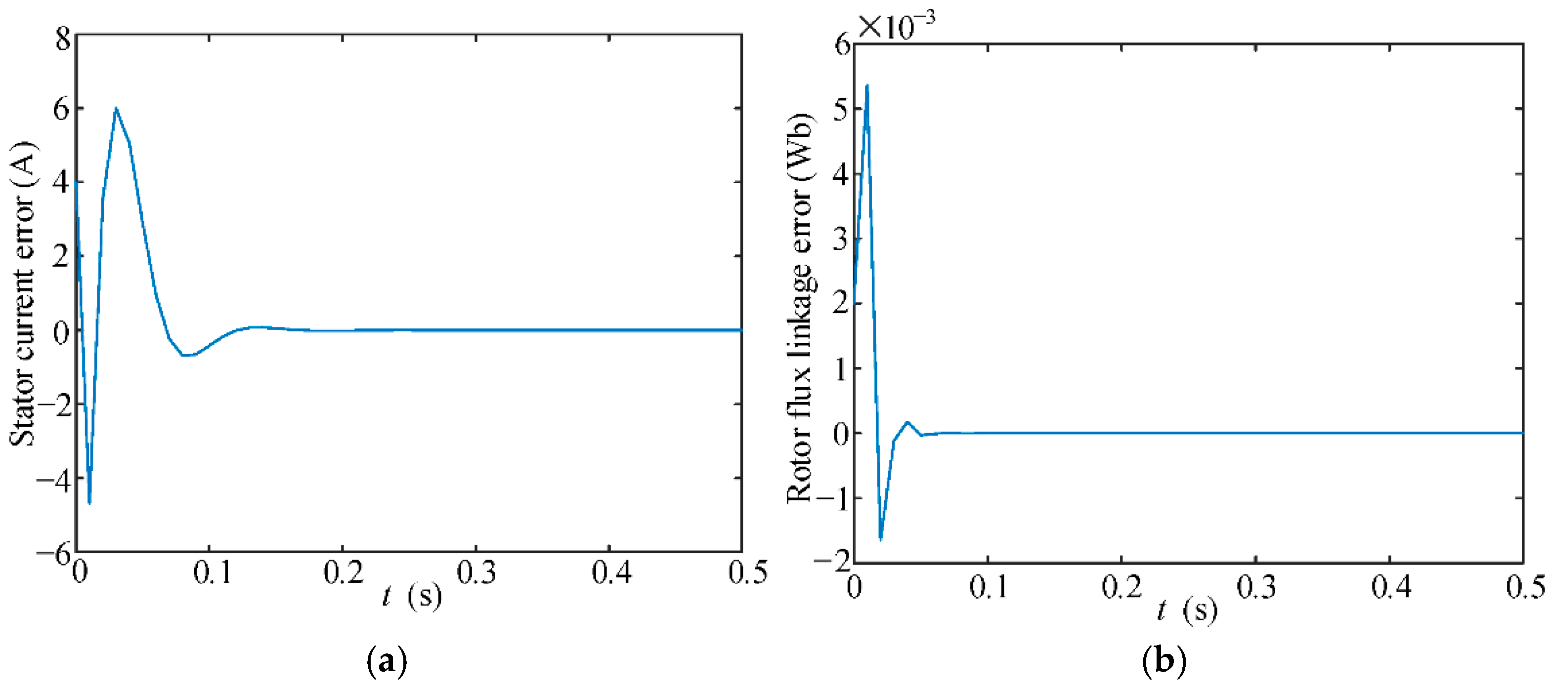
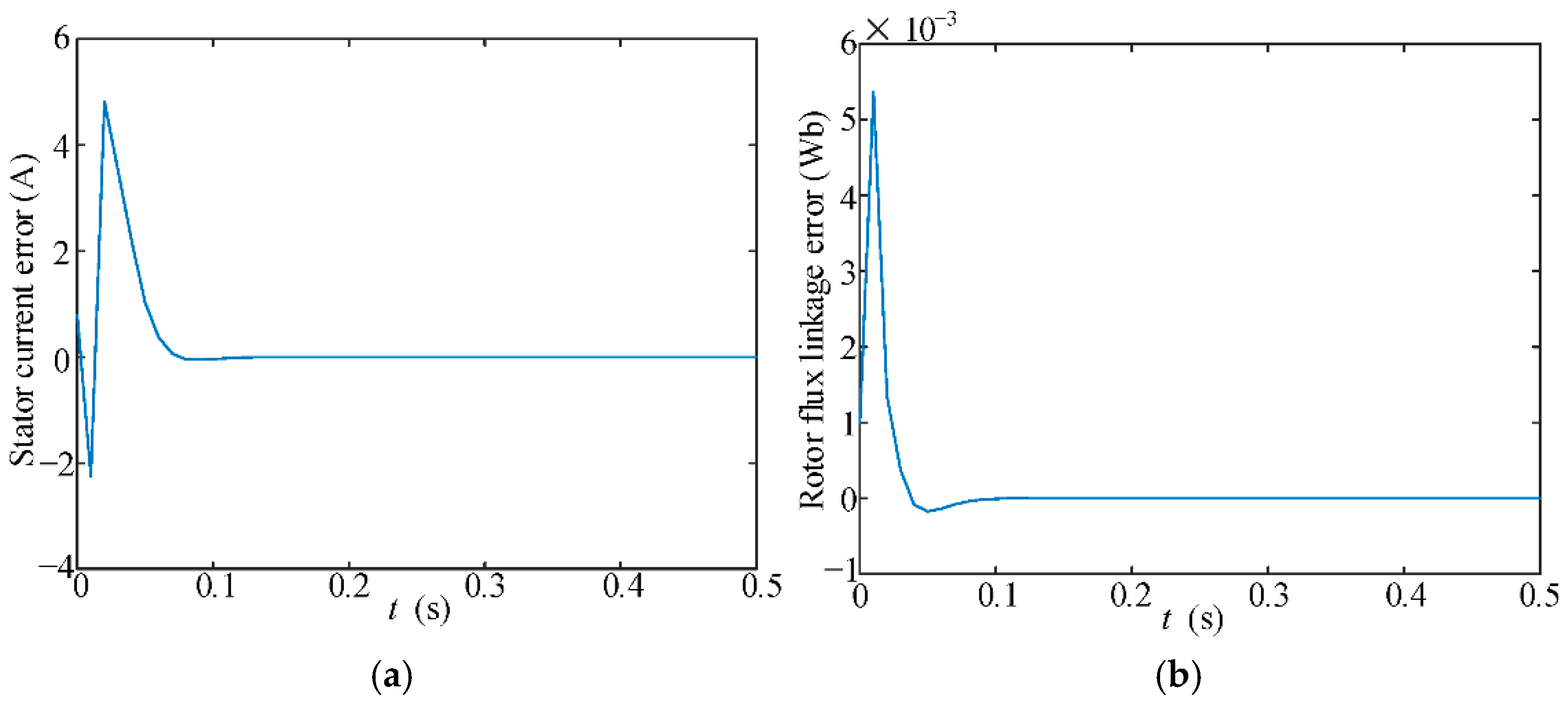
When the feedback matrix in (21) with k = 3 is introduced, the estimation errors of the stator current and rotor flux linkage are as shown in Figure 5. Meanwhile, when the feedback matrix in (24) with b = 500 is introduced, the estimation errors of the stator current and rotor flux linkage are as shown in Figure 6. Although the estimation errors of both methods tend to approach 0, the convergence time of the proposed method is less than that of the feedback matrix in (21). Meanwhile, the smaller oscillation amplitude can be obtained by the designed feedback matrix.

4.2. Speed Estimation Based on Current Error and Lyapunov Theory

Since the speed is unknown, Equation (9) needs to be rewritten as
d x ^ d t = A ^ x ^ + B u + G y y ^
By subtracting (9) from Equation (8), the following expression is obtained:
d e d t = A G C e Δ A x ^
where ΔA is the error state matrix and can be written as
Δ A = A ^ A = 0 ω ^ r ω r L m σ L s L r J 0 ω ^ r ω r J
Given that the speed estimation is a nonlinear system, according to Lyapunov stability theory, the sufficient condition for the asymptotic stability of a nonlinear system is that the Lyapunov function V(e) is positive definite and its first-order derivative dV/dt with respect to time is negative. The Lyapunov function is
V e = e T e + ω ^ r ω r 2 / λ
When A is a strictly positive constant, Equation (28) is always greater than or equal to zero and is equal to zero only when e = 0 and ω ^ r ω r = 0 . When dV/dt is negative, the error is a decreasing function, and the estimated value of the speed will gradually approach the actual value. The following equation can be obtained:
d V d t = e T d e d t + d e T d t e + 2 ω ^ r ω r λ d ω ^ r d t
Substituting (26) into (28), the following equation can be obtained:
d V d t = e T A G C T + A G C e e T Δ A x ^ + x ^ T Δ A T e + 2 ω ^ r ω r λ d ω ^ r d t
Since all eigenvalues of the observation matrix A G C have been configured to have negative real parts, A G C T + A G C is negative definite. Therefore, when the sum of the last two items of (30) is always zero, dV/dt can be always determined to be negative, that is,
e T Δ A x ^ + x ^ T Δ A T e + 2 ω ^ r ω r λ d ω ^ r d t = 0
Substituting (27) into (31), the following equation can be obtained:
2 L m σ L s L r ω ^ r ω r ψ ^ r T J i s i ^ s + 2 ω ^ r ω r ψ ^ r T J ψ r ψ ^ r + 2 ω ^ r ω r λ d ω ^ r d t = 0
When the estimated value and actual value of the rotor flux are equal, Equation (32) can be simplified as
d ω ^ r d t = K ψ ^ r T J ( i s i ^ s )
where K = λ L m σ L s L r .
By integrating (33), the following expression can be obtained:
ω ^ r = K ψ ^ r T J i s i ^ s d t
To achieve better performance, Equation (34) is rewritten as
ω ^ r = K p ψ ^ r T J i s i ^ s + K i ψ ^ r T J i s i ^ s d t = K p + K i p ψ ^ r T J i s i ^ s = K p + K i p ψ ^ r β i s α i ^ s α ψ ^ r α i s β i ^ s β
Thus, the rotor flux and speed of the IM can be estimated separately using a full-order state observer based on the stator current error.

5. Improvement in Low-Speed Performance of Full-Order State Observer

When the motor operates at low speed, the rotor flux leakage is prone to divergence, resulting in speed estimation error. This section improves the feedback matrix based on the stability conditions of d–q axis current error model, enhancing the low-speed operation capability of the full-order state observer.
Performing the Park transformation on Equation (15), the error equations of the observer in the rotating coordinate (d–q axis) can be obtained:
d e i s d t = ( A 11 G 1 ) e i s + A 12 e ψ r + L m σ L s L r Δ ω r J ψ r d e ψ r d t = ( A 21 G 2 ) e i s + A 22 e ψ r + Δ ω r J ψ r
where
G 1 = g 1 I g 2 J G 2 = g 3 I g 4 J A 11 = a 11 I ω e J A 22 = 1 T r I + ( ω r ω e ) J e i s = i s d i ^ s d i s q i ^ s q T e ψ r = ψ r d ψ ^ r d ψ r q ψ ^ r q T
The subscript symbols ‘d’ and ‘q’ denote the variables in d–q axes, respectively. Performing Laplace transform on the error in Equation (36), eis can be expressed as
e i s = G ω ( s ) J Δ ω r ψ ^ r = Δ ω r G ω ( s ) 0 ψ ^ r d
The expression of Gω(s) is shown as
G ω ( s ) = G 11 ( s ) G 12 ( s ) G 21 ( s ) G 22 ( s ) = L m σ L s L r ( s + j ω e ) [ ( s A 11 + G 1 ) ( s A 22 ) A 12 ( A 21 G 2 ) ] 1
The relationship between q-axis current error eisq and speed error Δωr can be described as
e i s q = G 22 ( s ) Δ ω r ψ ^ r d
The expression of G22(s) can be derived from Equations (36), (37) and (39); it is shown as
G 22 ( s ) = s 3 + m 2 s 2 + m 1 s + m 0 s 4 + n 3 s 3 + n 2 s 2 + n 1 s + n 0
where
m 0 = ( R s σ L s + L m σ L s L r T r + 1 T r + g 1 ) ω e 2 ω e [ ω r ( R s σ L s + g 1 + L m g 3 σ L s L r + g 2 T r + L m g 4 σ L s L r ) ] m 1 = ω e 2 + R s σ L s T r + g 1 T r g 2 ω r + L m g 3 σ L s L r L m g 4 σ L s L r m 2 = R s σ L s + L m σ L s L r T r + 1 T r + g 1
In order to achieve system stability within the full speed range, except for the poles of G22(s), the real parts of all zeros should be negative. The Routh table of the numerator of G22(s) is shown in Table 1.
The condition for observer stability is that all terms in the first row are greater than 0; the following conditions should be satisfied:
R s σ L s + L m 2 σ L s L r T r + 1 T r + g 1 > 0 R s σ L s T r + g 1 T r g 2 ω r + L m g 3 σ L s L r L m g 4 σ L s L r > 0 ω r ( R s σ L s + g 1 + L m g 3 σ L s L r ) + g 2 T r + L m g 4 σ L s L r = 0
When g4 is set to zero, the value range of the feedback matrix can be derived as
g 1 > ( R s σ L s + L m 2 σ L s L r T r + 1 T r ) g 2 = ω r ( R s σ L s T r + g 1 T r + L m g 3 σ L s L r ) g 3 > σ L s L r L m ( g 1 + R s σ L s )
The above feedback matrix only considers the q-axis current error. However, when the motor operates under low-speed load conditions, the influence of nonlinear voltage becomes prominent, resulting in a decrease in the d-axis current and an increase in the error between the estimated speed value and the actual value.
Decomposing Equation (36), the relationship between d-axis current error eisd and ωr can be obtained as
d e i s d d t = a 11 e i s d + a 12 e ψ r d ( ω e ω ^ e ) i s q + a 13 ω ^ r e ψ r d + ω ^ e e i s q + a 12 ( ω r ω ^ r ) ψ r q + g 1 e i s d g 2 e i s q
The Lyapunov function U of the d-axis current error is defined as
U = e i s d 2 2
Since rotor magnetic field orientation control is adopted in this paper, the following equation must be satisfied:
ψ r q = 0 ω e = ω ^ e ω r = ω ^ r ψ r d = L m i s d
According to (45) and (47), dU/dt can be simplified as
d U d t = e i s d d e i s d d t = e i s d 2 ( a 11 + a 12 L m + g 1 )
According to Lyapunov stability judgment criteria, the range of values for g1 can be obtained as
g 1 < ( a 11 + a 12 L m ) = R s σ L s
Let g3 be equal to zero. Substituting (46) into (44), the value of the feedback matrix under low speed conditions can be obtained as
g 1 = l R s σ L s g 2 = ( l + 1 ) ω r g 3 = 0 g 4 = 0
where l is less than 1. When the IM operates under a very low-speed condition, g2 can also be set to zero.

6. Simulation Verification

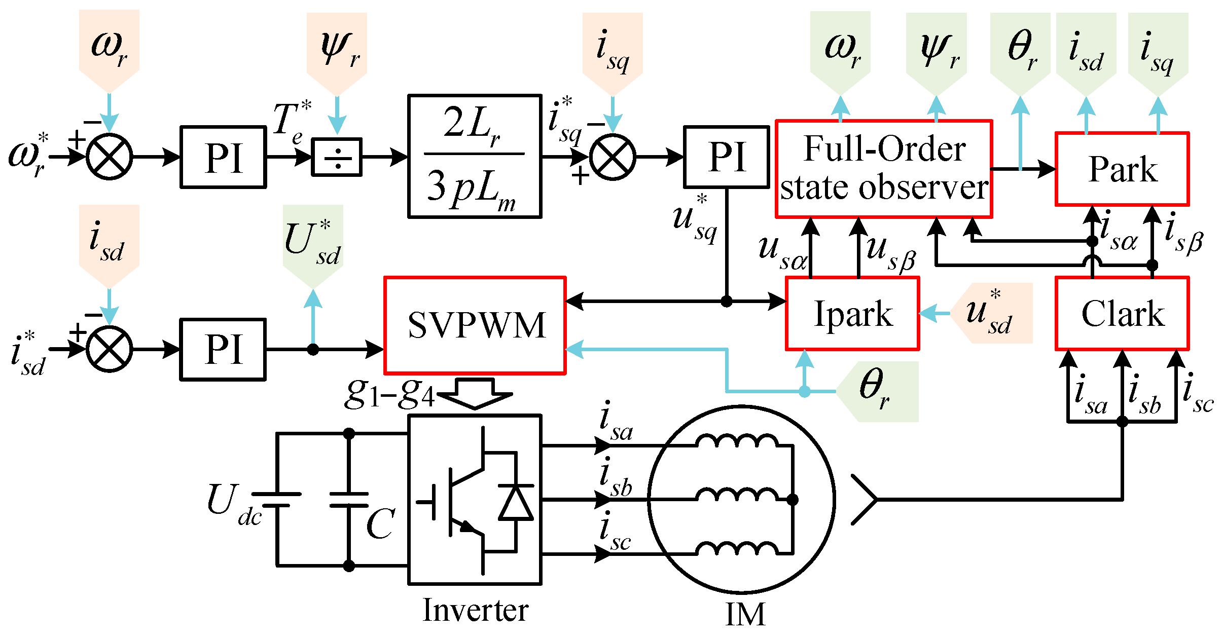
A closed-loop simulation model of the IM drive system fed by a voltage source inverter was established on the Simulink simulation platform in Matlab. On the basis of the vector control system shown in Figure 7, the effectiveness of the improved full-order state observer proposed in this paper is verified. The IM parameters are listed in Table 2.
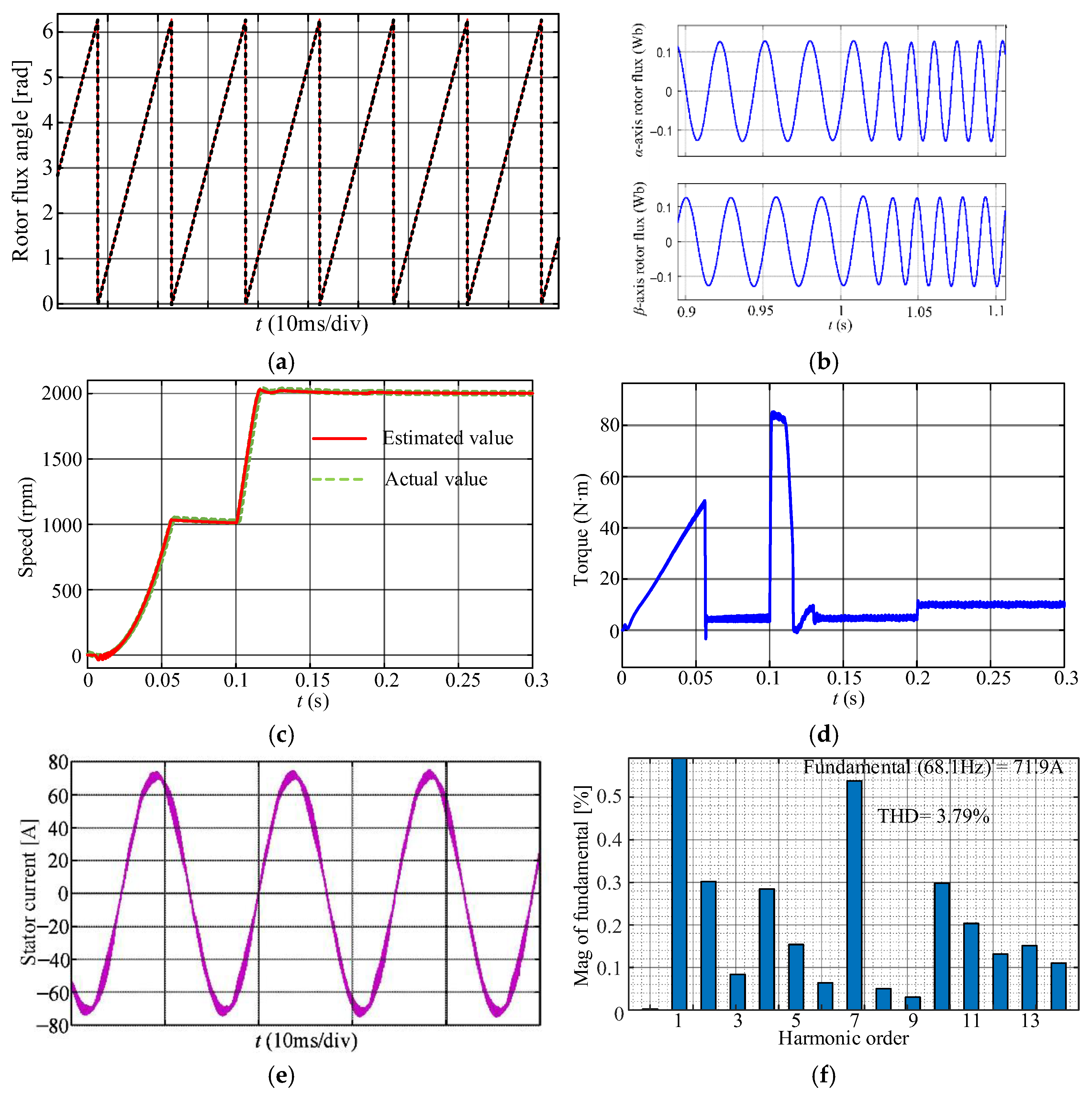
The simulation operating conditions are set as follows: the starting speed is set to 1000 rpm, and the load torque is set to 5 N·m. After the motor enters steady state, the speed reference increases to 2000 rpm at 0.1 s. Then, at 0.2 s, the load torque increases to 10 N·m. The simulation waveform of the entire process and current harmonic analysis results are shown in Figure 8. In Figure 8a, the black dashed line represents the rotor flux angle calculated by the actual speed and slip frequency, while the red solid line represents the rotor flux angle obtained by the improved full-order state observer proposed in this paper, where the actual speed is obtained by the physical model. It can be seen that the two methods obtain consistent results in the steady state. In Figure 8b, the waveforms of the rotor flux linkage in αβ axes are very smooth, and the rapid dynamic response is reflected in the stage of speed change. In Figure 8c, except for a slight error between the estimated speed and the actual speed during the start-up stage, the speed curve obtained by the improved full-order state observer proposed in this paper basically coincides with the actual speed curve output by the actual IM model. Since the improved full-order state observer can provide accurate speed feedback and rotor flux position for vector control systems, Figure 8d,e demonstrate good dynamic and steady-state performance. According to Figure 8f, the total harmonic distortion of the stator current is only 3.79%.

7. Experimental Verification

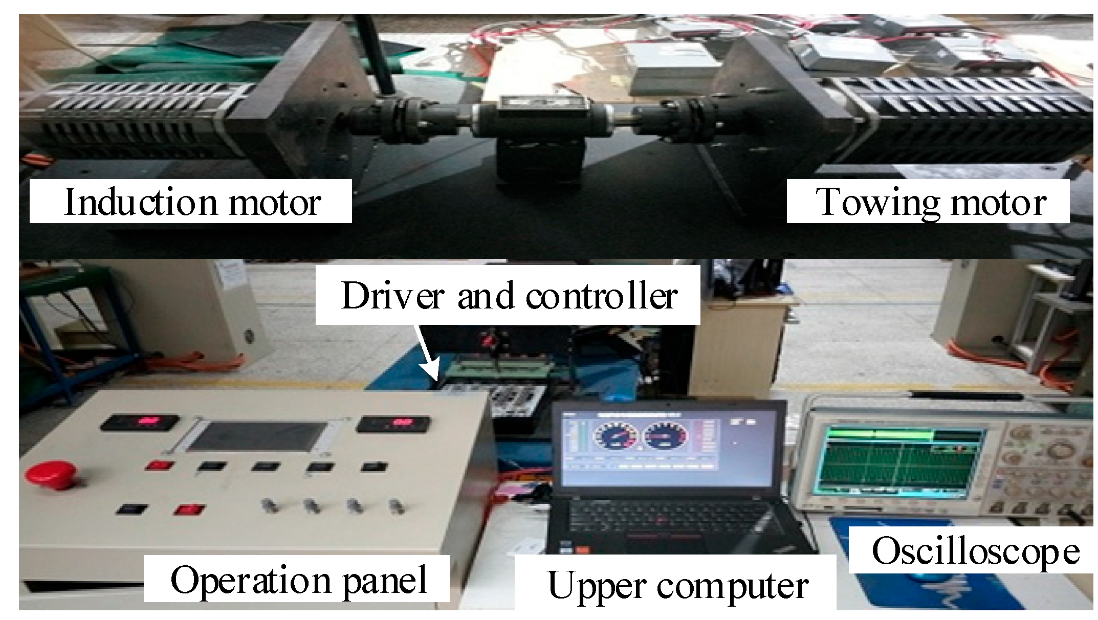
The experimental platform as shown in Figure 9 was established to verify the improved full-order state observer for IM; the modules and parameters of the experimental platform are listed in Table 3 [1]. The IM parameters were the same as in the simulation.
The sampling and control frequencies are both 15 kHz; the average execution time is 36.5 µs. A load torque of 5 N·m is provided by the towing motor; the speed reference increases step by step from 1000 rpm to 2000 rpm. The experimental waveforms of speed, torque, and current are shown in Figure 10a. The electromagnetic torque can increase rapidly, and the speed reaches 2000 rpm after 25 ms. There is no overshoot or oscillation in the entire dynamic process, and there is no steady-state error. The rotor flux position angle obtained based on the orthogonal encoder and IM flux linkage equation as well as the rotor flux position angle obtained using the improved full-order state observer proposed in this paper are shown in Figure 10b. The estimated and measured signals are output to the D/A module under the same clock frequency. The experimental waveforms of the rotor flux position obtained by the two methods is basically consistent, which is the same as the simulation result shown in Figure 8a.
Then the speed reference is set to 1500 rpm, and the load torque provided by the towing motor increases from 5 N·m to 10 N·m. The experimental waveforms of speed, torque, and current are shown in Figure 11a. Due to the observer’s ability to output accurate speed and rotor flux position angle for vector control systems, good steady-state and dynamic performance can be obtained. When the load torque suddenly increases, the electromagnetic torque can quickly follow, and the speed immediately returns to 1500 rpm with a slight decrease. There is no overshoot or oscillation in the dynamic process.
The harmonic analysis results of the stator current are shown in Figure 11b. Due to the addition of a dead time of 2 μs in the PWM signals, there is a seventh-order harmonic of 0.9% in the stator current. But the THD is only 5.38%, and the torque ripple is ±4%, exhibiting excellent power quality and performance.
The experimental results for low-speed operation under 50 rpm and 6 N·m are shown in Figure 12. Since the feedback matrix shown in (47) is adopted, the speed can still be accurately observed at low-speed operation, and good steady-state performance can be achieved. The THD of the stator current is 7.79%.
Under start-up operation, the proposed sensorless control scheme based on the full-order state observer is compared with the MRAS. The waveform of the speed is shown in Figure 13. Due to the pure integrators in adaptive structures, DC bias and initial integration values are introduced into flux linkage observations, resulting in errors in speed estimation during the start-up process. This paper improves the dynamic response speed by shifting the pole of the observer to the left by 500 s−1. After 10 ms, the estimated speed can follow the actual speed.

8. Conclusions

This paper proposes a sensorless induction motor control scheme based on an improved full-order state observer. The feasibility and effectiveness are verified by the simulation and experiment, and the following conclusions are formed:
(1) The full-order state observer for IM has a simple structure and low sensitivity to motor parameters, but the expression of the feedback matrix is complex and contains rotational speed, which may lead to the instability of the observer due to a large imaginary pole at high speed.
(2) By shifting the pole to the left and approaching infinity in rotational speed, a feedback matrix containing only constant terms is obtained. At this time, the stability of the observer is improved, and the digital implementation process is simplified.
(3) The speed estimation method based on the current error and Lyapunov theory is proposed, and the speed and rotor flux leakage can converge quickly without steady-state error. Since accurate speed feedback and rotor flux position can be obtained by the proposed observer, the IM drive system exhibits good steady-state and dynamic performance.

Author Contributions

Conceptualization, Q.X. (Qiuyue Xie); Methodology, Q.X. (Qiwei Xu) and L.L.; Software, Y.T.; Validation, Q.X. (Qiuyue Xie); Formal analysis, Y.T.; Resources, W.S.; Data curation, L.L.; Writing—original draft, Q.X. (Qiuyue Xie) and W.S.; Writing—review & editing, Q.X. (Qiwei Xu); Project administration, Q.X. (Qiwei Xu); Funding acquisition, W.S. All authors have read and agreed to the published version of the manuscript.

Funding

This research was funded by [National key research and development plan] grant number [2022YFB3403202], [Department of Education outstanding youth project of Hunan Provincial] grant number [23B0702], [ Chongqing City Natural Science Foundation Project] grant number [CSTB2022NSCQ-MSX0430], [Wenzhou basic scientific research project] grant number [S20240002] and [Wenzhou major scientific and technological innovation projects] grant number [ZG2024034].

Data Availability Statement

The original contributions presented in this study are included in the article. Further inquiries can be directed to the corresponding author.

Conflicts of Interest

The authors declare no conflict of interest.

References

  1. Xu, Q.; Yi, L.; Long, X.; Luo, L.; Miao, Y. Dead-Time Free Modulation Scheme for IM Drive System Fed by Voltage Source Inverter. Energies 2024, 17, 3845. [Google Scholar] [CrossRef]
  2. Park, D.-H.; Song, C.-H.; Won, Y.-J.; Park, J.-C.; Kim, H.-S.; Park, H.-R. Magnetizing Inductance Estimation Method of Induction Motor for EV Traction Considering Magnetic Saturation Changes According to Current and Slip Frequency. IEEE Trans. Magn. 2024, 60, 1–5. [Google Scholar] [CrossRef]
  3. Dong, Z.; Huang, R.; Liu, S.; Liu, C. Analysis of Winding-Connection Sequence in Multiphase Series-End Winding Motor Drives for Leg-Current Stress Reduction. IEEE Trans. Ind. Inform. 2025, 21, 1635–1644. [Google Scholar] [CrossRef]
  4. Zhang, Y.; Xu, X.; Song, Y.; Qi, W.; Guo, Q.; Li, X. Real-Time Global Optimal Energy Management Strategy for Connected PHEVs Based on Traffic Flow Information. IEEE Trans. Intell. Transp. Syst. 2024, 25, 20032–20042. [Google Scholar] [CrossRef]
  5. Hu, S.; Zhao, Z.; Bai, H.; Yuan, L. An Enhanced DC Preexcitation With Effective Flux-Linkage Control for the High-Power Induction Motor Drive System. IEEE Trans. Power Electron. 2011, 26, 2375–2380. [Google Scholar] [CrossRef]
  6. Qi, W.; Yang, J.; Zhang, Z.; Wu, J.; Lan, P.; Xiang, S. Investigation on thermal management of cylindrical lithium-ion batteries based on interwound cooling belt structure. Energy Convers. Manag. 2025, 340, 119962. [Google Scholar] [CrossRef]
  7. Chagam, V.S.R.; Devabhaktuni, S. An Isolation Transformer-less Single DC Source fed Dual 5-leg Inverter Controlled 5-Phase Induction Motor with Modified Direct Torque Control. IEEE Lat. Am. Trans. 2024, 22, 229–239. [Google Scholar] [CrossRef]
  8. Xu, Q.; Wang, Y.; Miao, Y.; Zhang, X. A Double Vector Model Predictive Torque Control Method Based on Geometrical Solution for SPMSM Drive in Full Modulation Range. IEEE Trans. Ind. Electron. 2025, 72, 5558–5568. [Google Scholar] [CrossRef]
  9. Mustafa, A.; Sasamura, T.; Morita, T. Sensorless Speed Control of Ultrasonic Motors Using Deep Reinforcement Learning. IEEE Sens. J. 2024, 24, 4023–4035. [Google Scholar] [CrossRef]
  10. Xu, C.; Liu, P.; Miao, Y. Overlap Time Compensation and Characteristic Analysis for Current Source Photovoltaic Grid-Connected Inverter. Energies 2024, 17, 1768. [Google Scholar] [CrossRef]
  11. Meira, M.; Bossio, G.R.; Verucchi, C.J.; Ruschetti, C.R.; Bossio, J.M. Speed Estimation During the Starting Transient of Induction Motors. IEEE Trans. Instrum. Meas. 2021, 70, 1–8. [Google Scholar] [CrossRef]
  12. Goel, R.; Roy, S.B. Closed-Loop Reference Model Based Distributed Model Reference Adaptive Control for Multi-Agent Systems. IEEE Control. Syst. Lett. 2021, 5, 1837–1842. [Google Scholar] [CrossRef]
  13. Liu, L.; Liu, D. Speed and flux observer based on adaptive linear neuron for induction motor. J. Power Electron. 2023, 23, 1379–1388. [Google Scholar] [CrossRef]
  14. Zerdali, E. Adaptive Extended Kalman Filter for Speed-Sensorless Control of Induction Motors. IEEE Trans. Energy Convers. 2019, 34, 789–800. [Google Scholar] [CrossRef]
  15. Mwasilu, F.; Jung, J.-W. Enhanced Fault-Tolerant Control of Interior PMSMs Based on an Adaptive EKF for EV Traction Applications. IEEE Trans. Power Electron. 2016, 31, 5746–5758. [Google Scholar] [CrossRef]
  16. Zhang, S.; Zhuang, W.; Li, B.; Li, K.; Xia, T.; Hu, B. Integration of Planning and Deep Reinforcement Learning in Speed and Lane Change Decision-Making for Highway Autonomous Driving. IEEE Trans. Transp. Electrif. 2025, 11, 521–535. [Google Scholar] [CrossRef]
  17. Komurcugil, H.; Zhang, Z.; Bayhan, S. Guest Editorial Special Section on Recent Advances on Sliding Mode Control and Its Applications in Modern Industrial Systems. IEEE Trans. Ind. Inform. 2020, 16, 1149–1152. [Google Scholar] [CrossRef]
  18. Yalavarthi, A.; Singh, B. Sensorless Speed Control of SRM Drive Using Optimized Neural Network Model for Rotor Position Estimation. IEEE Trans. Energy Convers. 2024, 39, 2158–2168. [Google Scholar] [CrossRef]
  19. Huang, Y.; Zhao, M.; Zhang, J.; Lu, M. The Hall Sensors Fault-Tolerant for PMSM Based on Switching Sensorless Control With PI Parameters Optimization. IEEE Access 2022, 10, 114048–114059. [Google Scholar] [CrossRef]
  20. Davari, S.A.; Khaburi, D.A.; Wang, F.; Kennel, R.M. Using Full Order and Reduced Order Observers for Robust Sensorless Predictive Torque Control of Induction Motors. IEEE Trans. Power Electron. 2012, 27, 3424–3433. [Google Scholar] [CrossRef]
  21. Sun, W.; Gao, J.; Yu, Y.; Wang, G.; Xu, D. Robustness Improvement of Speed Estimation in Speed-Sensorless Induction Motor Drives. IEEE Trans. Ind. Appl. 2016, 52, 2525–2536. [Google Scholar] [CrossRef]
  22. Xie, Q.; Xu, Q.; Yang, T.; Tu, Y. Internal Model Current Decoupling Control Strategy for Induction Motors. Energies 2025, 18, 2171. [Google Scholar] [CrossRef]
Figure 1. Topology of the induction motor drive system fed by VSI.
Energies 18 04374 g001
Figure 2. Structure diagram of full-order state observer.
Energies 18 04374 g002
Figure 3. Full-order state observer based on stator current error.
Energies 18 04374 g003
Figure 4. The trajectory of the observer poles under different feedback matrices.
Energies 18 04374 g004
Figure 5. The estimation errors under feedback matrix in (21) with k = 3. (a) Stator current. (b) Rotor flux linkage.
Energies 18 04374 g005
Figure 6. The estimation errors of feedback matrix designed in this paper. (a) Stator current. (b) Rotor flux linkage.
Energies 18 04374 g006
Figure 7. Sensorless control diagram for IM.
Energies 18 04374 g007
Figure 8. Simulation results of the sensorless control based on the improved full-order state observer for IM. (a) Rotor flux angle. (b) αβ axis rotor flux linkage. (c) Speed. (d) Torque. (e) Stator current. (f) Harmonic analysis results.
Energies 18 04374 g008
Figure 9. Experimental drag motor platform.
Energies 18 04374 g009
Figure 10. Experimental waveforms under the condition of increasing speed. (a) Speed, torque and current. (b) Rotor flux angle.
Energies 18 04374 g010
Figure 11. Experimental waveforms and harmonic analysis results under the condition of increasing load torque. (a) Waveforms. (b) Harmonic analysis results.
Energies 18 04374 g011
Figure 12. Experimental waveforms and harmonic analysis results under the conditions of 50 rpm and 6 N·m. (a) Waveforms. (b) Harmonic analysis results.
Energies 18 04374 g012
Figure 13. Experimental waveforms of estimated speed and actual speed. (a) MRAS. (b) Full-order state observer proposed in this paper.
Energies 18 04374 g013
Table 1. Routh table of the numerator of G22(s).
s3s2s1s0
1m2m1m0/m2m0
m1m000
Table 2. IM parameters.
ParametersValue
Rated voltage72 V
Rated frequency50 Hz
Rated power30 kW
Rated current200 A
Stator resistance0.052 Ω
Rotor resistance0.035 Ω
Stator leakage inductance16.3 μH
Rotor leakage inductance27.5 μH
Magnetic inductance1.43 mH
Number of pole pairs2
Table 3. Modules and parameters of the experimental platform.
CategoryPart NumberParameters
DC power supplyPR300-4 (YOKOGAWA, Tokyo, Japan)72 V
Switching tubes (IGBT)IPB042N10N (Infineon, Munich, Germany)100 V/100 A
Current sensorsMLX91205 (MELEXIS, Brussels, Belgium)/
Digital signal controllerTMS320F28035 (Texas Instruments, Dallas, TX, USA)/
EncoderOIH (Tamagawa, Tokyo, Japan)2500 C/T
Disclaimer/Publisher’s Note: The statements, opinions and data contained in all publications are solely those of the individual author(s) and contributor(s) and not of MDPI and/or the editor(s). MDPI and/or the editor(s) disclaim responsibility for any injury to people or property resulting from any ideas, methods, instructions or products referred to in the content.