Steel Hydrogen-Induced Degradation Diagnostics for Turbo Aggregated Rotor Shaft Repair Technologies
Abstract
1. Introduction
2. Materials and Methods
3. Results
3.1. Structural-Phase Approaches and Reflections
- new dislocations;
- new or displaced grain boundaries;
- substructures (subgrains);
- zones of local rearrangement;
- in some cases, heterogeneous formation of new grains (structure reformation).
3.2. Effect of Structural-Phase Composition Under Conditions of Gradual Hydrogen Charging on Machining
3.3. Electrochemical Investigation
4. Discussion
4.1. Common Provisions
4.2. The Main Reasons for the Movement of Carbides to the Grain Boundaries
4.2.1. Increased Diffusion Along Grain Boundaries
4.2.2. Dissolution of Intra-Grain Carbides
4.2.3. Redeposition of Carbides at Grain Boundaries
4.2.4. Growth and Coagulation of Carbides
4.2.5. The Effect of Thermal Aging
4.3. Influence of Alloying Elements and Microstructure Parameters on Diffusion and Hydrogen Embrittlement
4.4. Application of Screening Analyses and Computer Vision Methods
5. Conclusions
- −
- Regular chip analysis should be implemented as part of turbine maintenance protocols to monitor early-stage degradation and material instability.
- −
- Computer vision integration is recommended for the automated classification and morphometric evaluation of wear particles and cutting chips, enhancing diagnostic accuracy and consistency.
- −
- Machine learning algorithms should be developed and trained for intelligent classification of wear debris, utilizing shape, texture, and fractographic features as input parameters for failure prediction models.
- −
- In situ hydrogen detection techniques, including sensor-based or spectroscopic methods, should be investigated to enable real-time tracking of hydrogen transport and accumulation in rotor steel microstructures.
- −
- Comparative studies on alternative steel grades, such as Cr-Mo or Ni-based alloys, are needed to identify materials with superior resistance to hydrogen embrittlement under similar thermal and operational loads.
- −
- Microstructural evolution studies should focus on the role of secondary phases (e.g., σ-phase, Laves phase, intermetallics like Ni3Mo, Fe2Mo) in promoting localized embrittlement, especially at grain boundaries and carbide–matrix interfaces.
- −
- Finite element simulations and microstructure-based modeling can support the prediction of stress concentration zones, trap saturation effects, and critical hydrogen levels leading to mechanical failure.
Author Contributions
Funding
Data Availability Statement
Conflicts of Interest
Abbreviations
| TGV | turbogenerator with hydrogen cooling |
| TA | Turbo aggregate (turbine + turbogenerator) |
| TG | hydrogen-cooling turbogenerator |
| ppm | parts per million |
| Ecor | corrosion potential |
| Icor | corrosion current density |
| LCL | lubricating cooling liquid |
| LCLs | lubricating cooling liquid based on sunflower oils |
| LCLr | lubricating cooling liquid based on rapeseed oils |
| LCLp | lubricating cooling liquid based on petroleum oil |
| pH | indicator of the acidity or alkalinity of a solution |
| °C | degrees Celsius—Celsius temperature |
| Rz | roughness values (dry cutting) |
| Rzp | roughness values (after LCLp cutting) |
| Rzs | roughness values (after LCLs cutting) |
| CH | hydrogen concentration |
References
- Chernousenko, O.; Rindyuk, D.; Peshko, V.; Goryazhenko, V. Development of a Technological Approach to the Control of Turbine Casings Resource for Supercritical Steam Parameters. East. Eur. J. Enterp. Technol. 2018, 2, 51–56. [Google Scholar] [CrossRef]
- Gakal, P.; Ovsiannykova, O.; Przybysz, J.; Tretiak, O. Analysis of the temperature field of the rotor of 550-MW turbogenerator with direct hydrogen cooling. Prz. Elektrotechniczny 2017, 93, 43–47. Available online: http://pe.org.pl/articles/2017/2/11.pdf (accessed on 9 July 2025).
- Chernousenko, O.; Peshko, V.; Nikulenkova, T.; Rindyuk, D. Extension of the operating time of high-speed turbines of nuclear power plants. In Proceedings of the 2020 IEEE 7th International Conference on Energy Smart Systems (ESS), Kyiv, Ukraine, 2–4 November 2020; pp. 101–104. [Google Scholar] [CrossRef]
- Tretiak, O.; Kritskiy, D.; Kobzar, I.; Sokolova, V.; Arefieva, M.; Tretiak, I.; Denys, H.; Nazarenko, V. Modeling of the stress–strain of the suspensions of the stators of high-power turbogenerators. Computation 2022, 10, 191. [Google Scholar] [CrossRef]
- Kadhem, B.T.; Shuhati, H.W.; Alhasnawi, B.N.; Bureš, V. Account of Additional Factors for Damping Torsional Oscillations. Heliyon 2024, 10, e23995. [Google Scholar] [CrossRef] [PubMed]
- Manikandan, P.; Khan, F.A. Analysis of Multimode Oscillations Caused by Subsynchronous Resonance on Generator Shaft. Eur. J. Electr. Eng. 2018, 20, 455–468. [Google Scholar] [CrossRef]
- Dowson, D.; Bauer, D. Remaining Life Assessment of Steam Turbine and Hot Gas Expander Components. In Proceedings of the Asia Turbomachinery & Pump Symposium, Singapore, 22–25 February 2016. [Google Scholar] [CrossRef]
- Barella, S.; Bellogini, M.; Boniardi, M.; Cincera, S. Failure analysis of a steam turbine rotor. Eng. Fail. Anal. 2011, 18, 511–519. [Google Scholar] [CrossRef]
- Glotka, O.A. Distribution of Alloying Elements in Carbides of Refractory Nickel Alloys under the Conditions of Equiaxial Crystallization. Mater. Sci. 2021, 56, 714–721. [Google Scholar] [CrossRef]
- Ol’shanetskii, V.E.; Glotka, A.A.; Klochikhin, V.V. Prediction of carbide liquidus and carbide composition of the Ni-14Cr-9Co-5Ti-3AI-3Ta-3.5W-1.5Mo-0.15Hf-0.1C system. Functional Mater. 2021, 28, 359–365. [Google Scholar] [CrossRef]
- Glotka, A.A.; Moroz, A.N. Comparison of the effects of carbides and nonmetallic inclusions on formation of fatigue microcracks in steels. Metal Sci. Heat Treat. 2019, 61, 521–524. [Google Scholar] [CrossRef]
- Dmytrakh, I.M.; Leshchak, R.L.; Syrotyuk, A.M.; Barna, R.A. Effect of Hydrogen Concentration on Fatigue Crack Growth Behaviour in Pipeline Steel. Int. J. Hydrogen Energy 2017, 42, 6401–6408. [Google Scholar] [CrossRef]
- Dmytrakh, I.M.; Leshchak, R.L.; Syrotyuk, A.M. Effect of Hydrogen Concentration on Strain Behaviour of Pipeline Steel. Int. J. Hydrogen Energy 2015, 40, 4011–4018. [Google Scholar] [CrossRef]
- Ostash, O.P.; Vytvytskyi, V.I. Duality of the Action of Hydrogen on the Mechanical Behavior of Steels and Structural Optimization of Their Hydrogen Resistance. Mater. Sci. 2012, 47, 421–437. [Google Scholar] [CrossRef]
- Mohtadi-Bonab, M.A.; Szpunar, J.A.; Basu, R.; Eskandari, M. The Mechanism of Failure by Hydrogen Induced Cracking in an Acidic Environment for API 5L X70 Pipeline Steel. Int. J. Hydrogen Energy 2015, 40, 1096–1107. [Google Scholar] [CrossRef]
- Fan, Y.; Ma, C.; Li, S.; Ding, W.; Zhang, H. A Review on the Effect of Microstructure on Hydrogen Induced Cracking Behaviour in Pipeline and Pressure Vessel Steels. J. Phys. Conf. Ser. 2020, 1635, 012055. [Google Scholar] [CrossRef]
- Barrera, O.; Bombac, D.; Chen, Y.; Daff, T.D.; Galindo-Nava, E.; Gong, P.; Haley, D.; Horton, R.; Katzarov, I.; Kermode, J.R.; et al. Understanding and Mitigating Hydrogen Embrittlement of Steels: A Review of Experimental, Modelling and Design Progress from Atomistic to Continuum. J. Mater. Sci. 2018, 53, 6251–6290. [Google Scholar] [CrossRef] [PubMed]
- Martin, M.L.; Connolly, M.J.; DelRio, F.W.; Slifka, A.J. Hydrogen Embrittlement in Ferritic Steels. Appl. Phys. Rev. 2020, 7, 041302. [Google Scholar] [CrossRef] [PubMed]
- Khatib Zadeh Davani, R.; Mohtadi-Bonab, M.A.; Yadav, S.; Entezari, E.; Cabezas, J.F.A.; Szpunar, J. Effect of Quench Tempering on Hydrogen Embrittlement and Corrosion Behavior of X100 Pipeline Steel. Metals 2023, 13, 841. [Google Scholar] [CrossRef]
- International Atomic Energy Agency (IAEA). Mitigation of Hydrogen Hazards in Severe Accidents in Nuclear Power Plants; IAEA-TECDOC-1661; IAEA: Vienna, Austria, 2011; ISBN 978-92-0-116510-7. Available online: https://www-pub.iaea.org/mtcd/publications/pdf/te_1661_web.pdf (accessed on 5 May 2025).
- Park, B.; Kim, Y.; Hwang, I.-J. Risk Assessment of Explosion Accidents in Hydrogen Fuel-Cell Rooms Using Experimental Investigations and Computational Fluid Dynamics Simulations. Fire 2023, 6, 390. [Google Scholar] [CrossRef]
- International Atomic Energy Agency (IAEA). Hydrogen Phenomena During Severe Accidents in Water Cooled Reactors; IAEA-TCS-72; IAEA: Vienna, Austria, 2021; p. 90. ISSN 1018-551. Available online: https://www-pub.iaea.org/MTCD/publications/PDF/TCS-72web.pdf (accessed on 9 July 2025).
- Multinational Design Evaluation Programmer (MDEP). Design-Specific Technical Report TR-HPR1000WG-01: Hydrogen Control During Severe Accidents; OECD Nuclear Energy Agency: Paris, France, 2020; Available online: https://www.oecd-nea.org/mdep/documents/TR-HPR1000WG-01%20Hydrogen%20Control%20During%20Severe%20Accidents_clean%20copy_FINAL.pdf (accessed on 9 July 2025).
- Liu, F.; Sun, Z.; Ding, M.; Bian, H. Research Progress of Hydrogen Behaviors in Nuclear Power Plant Containment under Severe Accident Conditions. Int. J. Hydrogen Energy 2021, 46, 36477–36502. [Google Scholar] [CrossRef]
- Balitskii, A.I.; Syrotyuk, A.M.; Havrilyuk, M.R.; Balitska, V.O.; Kolesnikov, V.O.; Ivaskevych, L.M. Hydrogen Cooling of Turbo Aggregates and the Problem of Rotor Shafts Materials Degradation Evaluation. Energies 2023, 16, 7851. [Google Scholar] [CrossRef]
- Balitskii, A.I.; Havrilyuk, M.R.; Balitska, V.O.; Kolesnikov, V.O.; Ivaskevych, L.M. Increasing turbine hall safety by using fire-resistant, hydrogen-containing lubricant cooling liquid for rotor steel mechanical treatment. Energies 2023, 16, 535. [Google Scholar] [CrossRef]
- Jaworski, J.; Trzepiecínski, T. Research on durability of turning tools made of low-alloy high-speed steels. Kov. Mater. Met. Mater. 2016, 54, 17–25. [Google Scholar] [CrossRef]
- Jaworski, J.; Trzepieciński, T. Surface Layer Properties of Low-Alloy High-Speed Steel after Grinding. Acta Mech. Autom. 2016, 10, 275–279. [Google Scholar] [CrossRef][Green Version]
- Jaworski, J.; Trzepiecinski, T. Quality assurance of machine repair in production plants. Acta Metall. Slovaca 2017, 23, 387–393. [Google Scholar] [CrossRef]
- Korniy, S.A.; Zin, I.M.; Danyliak, M.-O.M.; Rizun, Y.Y. Eco-Friendly Metal Corrosion Inhibitors Based on Natural Polymers (A Review). Mater. Sci. 2023, 58, 567–578. [Google Scholar] [CrossRef]
- Korniy, S.A.; Zin, I.M.; Tymus, M.B.; Khlopyk, O.P.; Holovchuk, M.Y. Steel Corrosion Inhibition by Microbial Polysaccharide and Tartrate Mixture. J. Bio- Tribo-Corros. 2022, 8, 6. [Google Scholar] [CrossRef]
- Balyts’kyi, O.I.; Kolesnikov, V.O.; Havrylyuk, M.R. Influence of lubricating liquid on the formation of the products of cutting of 38KhN3MFA steel. Mater. Sci. 2019, 54, 722–727. [Google Scholar] [CrossRef]
- Balyts’kyi, O.I.; Kolesnikov, V.O.; Havrylyuk, M.R. Influence of modification of 38KhN3MFA steel on the structural-phase state and cutting products under variable technological conditions. Mater. Sci. 2020, 55, 915–920. [Google Scholar] [CrossRef]
- Balitskii, O.A.; Kolesnikov, V.O.; Balitskii, A.I.; Havrylyuk, M.R.; Eliasz, J. Hydrogen effect on the high-nickel surface steel properties during machining and wear with lubricants. Arch. Mater. Sci. Eng. 2020, 104, 49–57. [Google Scholar] [CrossRef]
- Atrens, A.; Liu, Q.; Tapia-Bastidas, C.; Gray, E.; Irwanto, B.; Venezuela, J.; Liu, Q. Influence of Hydrogen on Steel Components for Clean Energy. Corros. Mater. Degrad. 2020, 1, 3–26. [Google Scholar] [CrossRef]
- Smiyan, O.D. Hydrogen and Metal Fracture of Long-Term Operating Structures; Panasyuk, V.V., Ed.; E.O. Paton Electric Welding Institute of NAS of Ukraine, Naukova Dumka: Kyiv, Ukraine, 2018; 344p. [Google Scholar]
- Panait, C.; Bendick, W.; Fuchsmann, A.; Gourgues-Lorenzon, A.-F.; Besson, J. Study of the Microstructure of the Grade 91 Steel after More than 100,000 h of Creep Exposure at 600 °C. Preprint 2010. Available online: https://minesparis-psl.hal.science/hal-00509625/document (accessed on 6 May 2025).
- Dmytrakh, I.M.; Syrotyuk, A.M.; Leshchak, R.L. Fracture and Strength of Tubular Steels in Hydrogen-Containing Environments; Prostir-M: Lviv, Ukraine, 2020; 222p. [Google Scholar]
- Ostash, O.P.; Vol’demarov, O.V.; Hladysh, P.V. Cyclic crack Resistance of the Steels of Bends of Steam Pipelines After Long-Term Operation. Mater. Sci. 2013, 48, 427–437. [Google Scholar] [CrossRef]
- Ostash, O.P.; Vol’demarov, O.V.; Hladysh, P.V.; Ivasyshyn, A.D. Evaluation of the degradation of steels of steam pipelines according to their structural, mechanical, and electrochemical characteristics. Mater. Sci. 2011, 46, 431–439. [Google Scholar] [CrossRef]
- Anmark, N.; Karasev, A.; Jönsson, P.G. The Effect of Different Non-Metallic Inclusions on the Machinability of Steels. Materials 2015, 8, 751–783. [Google Scholar] [CrossRef]
- Hashimura, M.; Miyanishi, K.; Mizuno, A. Development of Low-Carbon Lead-Free Free-Cutting Steel Friendly to Environment. Nippon Steel Technical Report No. 96; 2007; pp. 45–49. Available online: https://www.nipponsteel.com/en/tech/report/nsc/pdf/n9608.pdf (accessed on 9 July 2025).
- Seo, D.; Toda, H.; Kobayashi, M.; Uesugi, K.; Takeuchi, A.; Suzuki, Y. In Situ Observation of Void Nucleation and Growth in a Steel Using X-ray Tomography. ISIJ Int. 2015, 55, 1474–1482. [Google Scholar] [CrossRef]
- Shinozuka, J.; Yachi, H.; Higashi, T.; Sando, M.; Maetani, T.; Unami, S.; Ozaki, Y. Effect of MnS on the Cutting Mechanism of Powder Metallurgy Steel in Cutting Speeds Ranging from 1 m/s to 150 m/s. Adv. Mater. Res. 2012, 565, 370–375. [Google Scholar] [CrossRef]
- Bruce, T.; Long, H.; Slatter, T.; Dwyer-Joyce, R.S. Formation of White Etching Cracks at Manganese Sulfide (MnS) Inclusions in Bearing Steel Due to Hammering Impact Loading. Wind Energy 2016, 19, 1903–1915. [Google Scholar] [CrossRef]
- Liu, S.; Yang, Z.; Wang, F. Behavior of MnS Inclusions during Homogenization Process in Low-Alloyed Steel FAS3420H. High Temp. Mater. Process 2021, 40, 66–76. [Google Scholar] [CrossRef]
- Xing, L.; Fan, X.; Wang, M.; Zhao, L.; Bao, Y. The Formation Mechanism of Proeutectoid Ferrite on Medium-Carbon Sulfur-Containing Bloom. Metall. Mater. Trans. B 2021, 52, 3208–3219. [Google Scholar] [CrossRef]
- Zhao, Y.; Li, T.; Tang, G.; Guo, H.; Yan, J.; Guo, X.; Zhu, Y. Characterization of the Morphological Evolution of MnS Inclusions in Free-Cutting Steel during Heating. J. Mater. Res. Technol. 2022, 17, 1427–1437. [Google Scholar] [CrossRef]
- Babei, Y.I. Mechanical Treatment as a Method of Increasing the Life of Construction Alloys in Active Media. Sov. Mater. Sci. 1975, 11, 129–138. [Google Scholar] [CrossRef]
- Nykyforchyn, H.M.; Lunarska, E.; Kyryliv, V.I.; Maksymiv, O.V. Hydrogen permeability of the surface nanocrystalline structures of carbon steel. Mater. Sci. 2014, 50, 67–73. [Google Scholar] [CrossRef]
- Nykyforchyn, H.; Lunarska, E.; Kyryliv, V.; Maksymiv, O. Influence of hydrogen on the mechanical properties of steels with the surface nanostructure. In Nanoplasmonics, Nano-Optics, Nanocomposites, and Surface Studies; Shpak, A.P., Ed.; Springer Proceedings in Physics; Springer: Cham, Switzerland, 2015; Volume 167, pp. 457–465. [Google Scholar]
- Balitskii, A.I.; Vytvytskyi, V.I.; Ivaskevich, L.M. The low-cycle fatigue of corrosion-resistant steels in high pressure hydrogen. Procedia Eng. 2010, 2, 2367–2371. [Google Scholar] [CrossRef]
- Tkachov, V.I.; Ivas’kevych, L.M.; Mochul’s’kyi, V.M. Temperature dependences of the mechanical properties of austenitic and martensitic steels in hydrogen. Mater. Sci. 2007, 43, 654–666. [Google Scholar] [CrossRef]
- Tkachov, V.I.; Ivas’kevych, L.M.; Vytvyts’kyi, V.I. Methodological aspects of determination of hydrogen resistance of steels. Methodological aspects of determination of hydrogen resistance of steels. Mater. Sci. 2002, 38, 484–493. [Google Scholar] [CrossRef]
- Maksimovich, G.G.; Tretyak, I.Y.; Ivas’kevich, L.M.; Slipchenko, T.V. Role of the martensite transformation in hydrogen embrittlement of unstable austenitic steels. Soviet Mater. Sci. 1986, 21, 320–323. [Google Scholar] [CrossRef]
- Tkachov, V.I.; Levina, I.M.; Ivas’kevych, L.M. Distinctive features of hydrogen degradation of heat-resistance alloys based on nickel. Mater. Sci. 1997, 33, 524–531. [Google Scholar] [CrossRef]
- Gu, Y.; Zhao, H.; Li, X.; Yan, W.; Xiong, L.; Chen, W.; Chen, D. Evolution of microstructure and changes in hydrogen embrittlement resistance of CLAM steel after long-term aging. Corros. Sci. 2024, 232, 112029. [Google Scholar] [CrossRef]
- Tang, L.; Liu, W.; Gao, B.-C.; Sha, J.-T.; Bai, R.-X.; Che, B.-H.; Xu, K.; Qiao, G.-Y.; Xiao, F.-R. Study on Hydrogen Embrittlement Behavior in Heat-Affected Zone of X80 Welded Pipe. Metals 2025, 15, 414. [Google Scholar] [CrossRef]
- Hai, C.; Zhu, Y.; Fan, E.; Du, C.; Cheng, X.; Li, X. Effects of the microstructure and reversed austenite on the hydrogen embrittlement susceptibility of Ni-Cr-Mo-V/Nb high-strength steel. Corros. Sci. 2023, 218, 111164. [Google Scholar] [CrossRef]
- Trautmann, A.; Mori, G.; Loder, B. Hydrogen Embrittlement of Steels in High Pressure H2 Gas and Acidified H2S-Saturated Aqueous Brine Solution. Berg. Hüttenmänn. Monatshefte 2021, 166, 450–457. [Google Scholar] [CrossRef]
- Rodoni, E.; Verbeken, K.; Depover, T.; Iannuzzi, M. Effect of Microstructure on the Hydrogen Embrittlement, Diffusion, and Uptake of Dual-Phase Low Alloy Steels with Varying Ferrite–Martensite Ratios. Int. J. Hydrogen Energy 2024, 50 Pt A, 53–65. [Google Scholar] [CrossRef]
- Balitska, V.; Filipecki, J.; Ingram, A.; Shpotyuk, O. Defect characterization methodology in sintered functional spinels with PALS technique. Phys. Status Solidi (C) 2007, 4, 1317–1320. [Google Scholar] [CrossRef]
- Balitska, V.; Shpotyuk, Y.; Filipecki, J.; Shpotyuk, O.; Iovu, M. Post-irradiation relaxation in vitreous arsenic/antimony trisulphides. J. Non-Cryst. Solids 2011, 357, 487–489. [Google Scholar] [CrossRef]
- Balitskii, O.I.; Kvasnytska, Y.H.; Ivaskevych, L.M.; Mialnitsa, H.P.; Kvasnytska, K.H. Fatigue fracture of the blades of gas-turbine engines made of a new refractory nickel alloy. Mater. Sci. 2022, 57, 475–483. [Google Scholar] [CrossRef]
- Balitskii, A.I.; Kvasnytska, Y.H.; Ivaskevych, L.M.; Kvasnytska, K.H.; Balitskii, O.A.; Shalevska, I.A.; Shynskii, O.Y.; Jaworski, J.M.; Dowejko, J.M. Hydrogen and Corrosion Resistance of Nickel Superalloys for Gas Turbines, Engines Cooled Blades. Energies 2023, 16, 1154. [Google Scholar] [CrossRef]
- Kvasnytska, Y.H.; Ivaskevich, L.M.; Balitskii, A.I.; Kvasnytska, K.H.; Mialnitsa, H.P. Structural and mechanical properties of the nickel alloy of gas-turbine engine blades. Mater. Sci. 2022, 57, 688–694. [Google Scholar] [CrossRef]
- Kawiak, M.; Balitskii, A. Embrittlement of welded joints of tram rails in city environments. Eng. Fail. Anal. 2018, 85, 97–103. [Google Scholar] [CrossRef]
- Ivas’kevych, L.M. Influence of Alloying with Cobalt and Hafnium on the Corrosion and Hydrogen Resistances of Refractory Nickel Alloy. Mater. Sci. 2020, 55, 730–736. [Google Scholar] [CrossRef]
- Godec, M.; Skobir Balantič, D. Coarsening Behaviour of M23C6 Carbides in Creep-Resistant Steel Exposed to High Temperatures. Sci. Rep. 2016, 6, 29734. [Google Scholar] [CrossRef]
- Li, Z.; Jia, P.; Liu, Y.; Qi, H. Carbide Precipitation, Dissolution, and Coarsening in G18CrMo2–6 Steel. Metals 2019, 9, 916. [Google Scholar] [CrossRef]
- Yu, X.F.; Zheng, D.Y.; Yang, X.F.; Wang, S.Y.; An, M.; Yan, G.B.; Xia, Y.Z.; Xing, F. Effect of Carbide Precipitation Behavior at High Temperatures on Microstructure and Mechanical Properties of M50 Steel. J. Mater. Res. Technol. 2022, 18, 1155–1165. [Google Scholar] [CrossRef]
- Lv, X.; Chen, S.; Rong, L. Evolution of Precipitate and Its Effect on the Degradation of Impact Toughness in a Carbon- and Nitrogen-Controlled 316 Stainless Steel during Thermal Aging at 650 °C. J. Mater. Res. Technol. 2024, 33, 3728–3742. [Google Scholar] [CrossRef]
- Han, Y.; Xue, X.; Zhang, T.; Hu, R.; Li, J. Grain Boundary Character Correlated Carbide Precipitation and Mechanical Propertiesof Ni-20Cr-18W-1Mo Superalloy. Mater. Sci. Eng. A 2016, 667, 391–401. [Google Scholar] [CrossRef]
- Liu, T.; Yang, M.; Han, F.; Dong, J. Influence Mechanism of Silicon on Carbide Phase Precipitation of a Corrosion Resistance Nickel Based Superalloy. Materials 2020, 13, 959. [Google Scholar] [CrossRef]
- Xia, S.; Ma, Y.; Bai, Q. Effects of the Primary Carbide Distribution on the Evolution of the Grain Boundary Character Distribution in a Nickel-Based Alloy. Metals 2024, 14, 960. [Google Scholar] [CrossRef]
- Specialty Steel Industry of North America. Intergranular Corrosion. Available online: https://www.ssina.com/education/corrosion/intergranular-corrosion (accessed on 9 July 2025).
- Tanaka, Y.; Pahlevani, F.; Moon, S.C.; Sahajwalla, V. In situ Characterisation of MnS Precipitation in High Carbon Steel. Sci. Rep. 2019, 9, 10096. [Google Scholar] [CrossRef] [PubMed]
- Duan, Z.; Man, C.; Cui, H.; Cui, Z.; Wang, X. Formation Mechanism of MnS Inclusion during Heat Treatments and Its Influence on the Pitting Behavior of 316L Stainless Steel Fabricated by Laser Powder Bed Fusion. Corros. Commun. 2022, 7, 12–22. [Google Scholar] [CrossRef]
- Liu, W.; Li, M.; Yang, S.; Xu, Z.; Huang, C.; Liu, T.; Li, J. Diffusion and Precipitation of MnS at Interface between Mn–Al–Si Oxides and Steel during Solidification. J. Mater. Res. Technol. 2022, 18, 990–997. [Google Scholar] [CrossRef]
- Sui, H.; Wang, L.; Wang, Q.; Wang, H.; Che, D.; Li, J.; Chou, K. The Formation and Growth of Sulfides in Free-Cutting Stainless Steel. Steel Res. Int. 2018, 89, 1800179. [Google Scholar] [CrossRef]
- Zhang, H.; Feng, G.; Liu, X.; Wang, B.; Liu, X. Effect of Sulfur Content on the Composition of Inclusions and MnS Precipitation Behavior in Bearing Steel. Metals 2020, 10, 570. [Google Scholar] [CrossRef]
- Wang, F.; Guo, H.; Liu, W.; Yang, S.; Zhang, S.; Li, J. Control of MnS Inclusions in High- and Low-Sulfur Steel by Tellurium Treatment. Materials 2019, 12, 1034. [Google Scholar] [CrossRef]
- Yu, Q.; Yang, X.; Lai, C.; Tong, Z. Study on MnS Inclusion Aggregation along Continuous Casting Slab Thickness of Medium Carbon Structural Steel. Metals 2022, 12, 56. [Google Scholar] [CrossRef]
- Lee, S.-H.; Na, H.-S.; Lee, K.-W.; Choe, Y.; Kang, C.Y. Microstructural Characteristics and M23C6 Precipitate Behavior of the Course-Grained Heat-Affected Zone of T23 Steel without Post-Weld Heat Treatment. Metals 2018, 8, 170. [Google Scholar] [CrossRef]
- Balyts’kyi, O.I.; Ivas’kevych, L.M.; Mochul’s’kyi, V.M. Mechanical properties of martensitic steels in gaseous hydrogen. Strength Mater. 2012, 44, 64–71. [Google Scholar] [CrossRef]
- Janovec, J.; Svoboda, M.; Kroupa, A.; Šob, M. Thermal-Induced Evolution of Secondary Phases in Cr–Mo–V Low Alloy Steels. J. Mater. Sci. 2006, 41, 3425–3433. [Google Scholar] [CrossRef]
- Kim, H.-P.; Park, Y.-M.; Jang, H.-M.; Lim, S.-Y.; Choi, M.-J.; Kim, S.-W.; Kim, D.-J.; Hwang, S.-S.; Lim, Y.-S. Early-Stage M23C6 Morphology at the Phase Boundary in Type 304L Austenitic Stainless Steel Containing δ Ferrite. Metals 2022, 12, 1794. [Google Scholar] [CrossRef]
- Oanh, N.T.H.; Viet, N.H. Precipitation of M23C6 Secondary Carbide Particles in Fe-Cr-Mn-C Alloy during Heat Treatment Process. Metals 2020, 10, 157. [Google Scholar] [CrossRef]
- Silva, F.J.G.; Santos, J.; Gouveia, R. Dissolution of Grain Boundary Carbides by the Effect of Solution Annealing Heat Treatment and Aging Treatment on Heat-Resistant Cast Steel HK30. Metals 2017, 7, 251. [Google Scholar] [CrossRef]
- Zheng, L.; Ding, Z. Characterization of M23C6 Carbides Precipitating at Grain Boundaries in 100Mn13 Steel. Metall. Mater. Trans. A 2016, 47, 4893–4901. [Google Scholar] [CrossRef]
- Zhang, Y.; Zhang, Z.; Wang, H.; Li, J.; Xu, X. The Effect of Precipitate Evolution on Austenite Grain Growth in Reduced Activation Ferritic/Martensitic Steel. Materials 2017, 10, 1017. [Google Scholar] [CrossRef]
- Yang, Z.; Jin, S.; Song, L.; Zhang, W.; You, L.; Guo, L. Dissolution of M23C6 and New Phase Re-Precipitation in Fe Ion-Irradiated RAFM Steel. Metals 2018, 8, 349. [Google Scholar] [CrossRef]
- Yang, Z.; Li, K.; Li, J.; Cheng, J.; Qian, C.; Cai, J.; Huo, X.; Liu, X.; Li, S.; Liu, Q.; et al. Effects of Heating Methods on Precipitation Behavior and Nucleation Activation Energy of γ′ Phase in Iron–Nickel-Based Alloy. Metals 2025, 15, 345. [Google Scholar] [CrossRef]
- Golański, G.; Zieliński, A.; Sroka, M.; Słania, J. The Effect of Service on Microstructure and Mechanical Properties of HR3C Heat-Resistant Austenitic Stainless Steel. Materials 2020, 13, 1297. [Google Scholar] [CrossRef] [PubMed]
- Meixner, F.; Ahmadi, M.R.; Sommitsch, C. Cavity Nucleation and Growth in Nickel-Based Alloys during Creep. Materials 2022, 15, 1495. [Google Scholar] [CrossRef]
- Elsevier. Grain Boundary Carbide—An Overview. ScienceDirect Topics. Available online: https://www.sciencedirect.com/topics/engineering/grain-boundary-carbide (accessed on 9 July 2025).
- Avila, D.D.S.; Offerman, S.E.; Santofimia, M.J. Modeling the Effect of Prior Austenite Grain Size on Bainite Formation Kinetics. Acta Mater. 2024, 266, 119656. [Google Scholar] [CrossRef]
- Long, X.; Zhang, F.; Yang, Z.; Zhang, M. Study on Bainitic Transformation by Dilatometer and In Situ LSCM. Materials 2019, 12, 1534. [Google Scholar] [CrossRef]
- Yao, X.; Huang, J.; Qiao, Y.; Sun, M.; Wang, B.; Xu, B. Precipitation Behavior of Carbides and Its Effect on the Microstructure and Mechanical Properties of 15CrNi3MoV Steel. Metals 2022, 12, 1758. [Google Scholar] [CrossRef]
- Sroka, M.; Zieliński, A.; Golański, G.; Pawlyta, M.; Purzyńska, H.; Novy, F. Evolution of the Microstructure and Mechanical Properties of Sanicro 25 Austenitic Stainless Steel after Long-Term Ageing. Arch. Civ. Mech. Eng. 2023, 23, 149. [Google Scholar] [CrossRef]
- Ma, Y.; Kuang, C.; Cheng, J.; Yang, C. Influence of the Evolution of 9CrMoCoB Steel Precipitates on the Microstructure and Mechanical Properties during High-Temperature Aging. J. Mater. Eng. Perform. 2021, 30, 9029–9037. [Google Scholar] [CrossRef]
- Zhou, Y.; Aust, K.T.; Erb, U.; Palumbo, G. Effects of Grain Boundary Structure on Carbide Precipitation in 304L Stainless Steel. Scripta Mater. 2001, 45, 49–54. [Google Scholar] [CrossRef]
- Wang, X.; Xu, L.; Jiao, L.; Mei, J.; Zhao, Y.; Qiao, L. Microstructure Evolution during Aging and Its Effect on Mechanical Properties of a Novel Nano-Carbide Dispersion Strengthened Steel. Mater. Sci. Eng. A 2025, 928, 148064. [Google Scholar] [CrossRef]
- Liu, D.; Ding, H.; Han, D.; Cai, M. Effect of Grain Interior and Grain Boundary κ-Carbides on the Strain Hardening Behavior of Medium-Mn Lightweight Steels. Mater. Sci. Eng. A 2023, 871, 144861. [Google Scholar] [CrossRef]
- Fang, K.; Luo, K.; Wang, L. Effect of Microstructure on Mechanical Properties of 316 LN Austenitic Stainless Steel. Coatings 2022, 12, 1461. [Google Scholar] [CrossRef]
- Huh, C.; An, S.; Kim, M.; Kim, C. Effect of Corrosion Characteristics on Long-Term Aging of Austenitic 304 Steel. Appl. Sci. 2019, 9, 5557. [Google Scholar] [CrossRef]
- Wang, Z.; Gao, F.; Tang, S.; Zhou, P.; Zhang, W.; Liu, Z. Effect of Twin-Related Boundaries Distribution on Carbide Precipitation and Intergranular Corrosion Behavior in Nuclear-Grade Higher Carbon Austenitic Stainless Steel. Corros. Sci. 2022, 209, 110791. [Google Scholar] [CrossRef]
- Aditya, D.M.; Ardy, H.; Lantang, Y.S.F.; Afrianti, Y.S.; Ilmi, N.F.F.; Pasaribu, U.S. The Study of Sigma and Carbide in Cast Austenitic Stainless-Steel Grade HH after 24 Years of High-Temperature Service. Heliyon 2023, 9, e14109. [Google Scholar] [CrossRef]
- Lin, M.; Gottstein, G.; Shvindlerman, L.S. Generalized Gibbs–Thomson Equation for Nanoparticles at Grain Boundaries. Acta Mater. 2017, 129, 361–365. [Google Scholar] [CrossRef]
- Banis, A.; Gomez, A.; Bliznuk, V.; Dutta, A.; Sabirov, I.; Petrov, R.H. Microstructure Evolution and Mechanical Behavior of Fe–Mn–Al–C Low-Density Steel upon Aging. arXiv 2023, arXiv:2305.00481. [Google Scholar] [CrossRef]
- Zhang, B.-G.; Zhang, X.-M.; Liu, H.-T. Precipitation Behavior of B2 and κ-Carbide during Aging and Its Effect on Mechanical Properties in Al-Containing High Strength Steel. Mater. Charact. 2021, 178, 111291. [Google Scholar] [CrossRef]
- Balyts’kyi, O.I.; Kostyuk, I.F. Strength of welded joints of Cr-Mn steels with elevated content of nitrogen in hydrogen-containing media. Mater. Sci. 2009, 1, 97–107. [Google Scholar] [CrossRef]
- Jürgensen, J.; Frehn, A.; Ohla, K.; Stolz, S.; Pohl, M. Effect of Hydrogen Charging on the Mechanical Properties of High-Strength Copper-Base Alloys, Austenitic Stainless Steel AISI 321, Inconel 625 and Ferritic Steel 1.4511. Metals 2024, 14, 588. [Google Scholar] [CrossRef]
- Nanninga, N.E. Effect of Microstructure and Alloying Elements on the Resistance of Fastener Grade Steels to Hydrogen Assisted Cracking. Master’s Thesis, Michigan Technological University, Houghton, MI, USA, 2005. Available online: https://digitalcommons.mtu.edu/cgi/viewcontent.cgi?article=1023&context=etds (accessed on 9 July 2025).
- Balyts’kyi, O.I.; Krokhmal’nyi, O.O. Pitting corrosion of 12Kh18AG18Sh steel in chloride solutions. Mater. Sci. 1999, 35, 389–394. [Google Scholar] [CrossRef]
- Zhang, S.; Wan, J.; Zhao, Q.; Liu, J.; Huang, F.; Huang, Y.; Li, X. Dual Role of Nanosized NbC Precipitates in Hydrogen Embrittlement Susceptibility of Lath Martensitic Steel. Corros. Sci. 2020, 164, 108345. [Google Scholar] [CrossRef]
- Fan, E.; Zhang, S.; Xie, D.; Zhao, Q.; Li, X.; Huang, Y. Effect of Nanosized NbC Precipitates on Hydrogen-Induced Cracking of High-Strength Low-Alloy Steel. Int. J. Miner. Metall. Mater. 2021, 28, 249–256. [Google Scholar] [CrossRef]
- Evers, S.; Hickel, T.; Koyama, M.; Nazarov, R.; Rohwerder, M.; Neugebauer, J.; Raabe, D.; Stratmann, M. Microstructure Effects on Hydrogen Embrittlement in Austenitic Steels: A Multidisciplinary Investigation. Max Planck Institute for Iron Research. Available online: https://www.mpie.de/3173155/Hydrogen-Embrittlement (accessed on 9 July 2025).
- Cho, L.; Kong, Y.; Speer, J.G.; Findley, K.O. Hydrogen Embrittlement of Medium Mn Steels. Metals 2021, 11, 358. [Google Scholar] [CrossRef]
- Nanninga, N.; Grochowsi, J.; Heldt, L.; Rundman, K. Role of Microstructure, Composition and Hardness in Resisting Hydrogen Embrittlement of Fastener Grade Steels. Corros. Sci. 2010, 52, 1237–1246. [Google Scholar] [CrossRef]
- Balyts’kyi, O.I.; Kolesnikov, V.O. Investigation of the Wear Products of Austenitic Manganese Cast Irons. Mater. Sci. 2004, 40, 78–82. [Google Scholar] [CrossRef]
- Balyts’kyi, O.I.; Kolesnikov, V.O.; Kubicki, E. Enhancement of the Crack Resistance of Manganese Cast Irons. Mater. Sci. 2005, 41, 67–73. [Google Scholar] [CrossRef]
- Balytskyi, O.I.; Kolesnikov, V.O.; Kaviak, P. Tribotechnical Properties of Austenitic Manganese Steels and Cast Irons under Sliding Friction Conditions. Fiz.-Khim. Mekh. Mater. 2005, 41, 55–60, ISSN 0430-6252. Available online: https://www.scopus.com/record/display.uri?eid=2-s2.0-33645644956&origin=resultslist&sort=plf-f&src=s&sid=4f73bdf9754dfdac7256947d377c3271&sot=autdocs&sdt=autdocs&sl=17&s=AU-ID%288918120300%29&relpos=5&citeCnt=0&searchTerm= (accessed on 9 July 2025).
- Balitskii, A.; Kolesnikov, V.; Abramek, K.F.; Balitskii, O.; Eliasz, J.; Marya, H.; Ivaskevych, L.; Kolesnikova, I. Influence of Hydrogen-Containing Fuels and Environmentally Friendly Lubricating Coolant on Nitrogen Steels’ Wear Resistance for Spark Ignition Engine Pistons and Rings Kit Gasket Set. Energies 2021, 14, 7583. [Google Scholar] [CrossRef]
- Balitskii, O.A.; Kolesnikov, V.O.; Balitskii, A.I. Wear resistance of hydrogenated high nitrogen steel at dry and solid state lubricants assistant friction. Arch. Mater. Sci. Eng. 2019, 2, 57–67. [Google Scholar] [CrossRef]
- Balyts’kyi, O.I.; Kolesnikov, V.O.; Eliasz, J. Study of the Wear Resistance of High-Nitrogen Steels under Dry Sliding Friction. Mater. Sci. 2013, 48, 642–646. [Google Scholar] [CrossRef]
- Balitskii, A.A.; Kolesnikov, V.A.; Vus, O.B. Tribotechnical properties of nitrogen manganese steels under rolling friction at addition of (GaSe)xIn1−x powders into contact zone. Metallofiz. I Noveishie Tekhnologii. 2010, 32, 685–695. Available online: http://scholar.google.com/scholar_lookup?title=Tribotechnical+properties+of+nitrogen+manganese+steels+under+rolling+friction+at+addition+of+(GaSe)xIn1%E2%88%92x+powders+into+contact+zone&author=Balitskii,+A.A.&author=Kolesnikov,+V.A.&author=Vus,+O.B.&publication_year=2010&journal=Metallofiz.+I+Noveishie+Tekhnologii.&volume=32&pages=685%E2%80%93695 (accessed on 9 July 2025).
- Balitskii, A.I.; Syrotyuk, A.M.; Ivaskevich, L.M.; Balitskii, O.A.; Kochmanski, P.; Kolesnikov, V.O. Hydrogen Accelerated Nanopore Nucleation, Crack Initiation and Propagation in the Ni–Co Superalloys. Int. J. Hydrogen Energy 2024, 82, 320–332. [Google Scholar] [CrossRef]
- Balitskii, O.I.; Kolesnikov, V.O.; Ivaskevych, L.M.; Havrylyuk, M.R. The Influence of Specific Features of Load and Hydrogen Charging on Steel Tribotechnical Properties. Mater. Sci. 2023, 58, 505–512. [Google Scholar] [CrossRef]
- Balyts’kyi, O.I.; Kolesnikov, V.O. Investigation of Wear Products of High-Nitrogen Manganese Steels. Mater. Sci. 2009, 45, 576–581. [Google Scholar] [CrossRef]
- Skalskyi, V.; Nazarchuk, Z.Z.; Stankevych, O.; Klym, B. Influence of Occluded Hydrogen on Magnetoacoustic Emission of Low-carbon Steels. Int. J. Hydrogen Energy 2023, 48, 6146–6156. [Google Scholar] [CrossRef]
- Balyts’kyi, O.I. Effect of Hydrogen on Structural Strength of High-nitrogen Chromium–manganese Steels. Mater. Sci. 2000, 36, 541–545. [Google Scholar] [CrossRef]
- Balitskii, A.; Kindrachuk, M.; Volchenko, D.; Abramek, K.F.; Balitskii, O.; Skrypnyk, V.; Zhuravlev, D.; Bekish, I.; Ostashuk, M.; Kolesnikov, V. Hydrogen Containing Nanofluids in the Spark Engine’s Cylinder Head Cooling System. Energies 2022, 15, 59. [Google Scholar] [CrossRef]
- Balyts’kyi, O.I.; Kolesnikov, V.O.; Kawiak, P. Triboengineering Properties of Austenitic Manganese Steels and Cast Irons under the Conditions of Sliding Friction. Mater. Sci. 2005, 41, 624–630. [Google Scholar] [CrossRef]
- Balitskii, A.I.; Syrotyuk, A.M.; Kolesnikov, V.O.; Balitska, V.O.; Ivaskevych, L.M.; Havrilyuk, M.R. The Effect of Absorbed Hydrogen on the Rotors of Steel Machining Products During Powerful Turbo Aggregate Repairs. Materials 2024, 17, 6257. [Google Scholar] [CrossRef]
- Laghari, M.; Hassan, A.; Haggag, M.; Wahyudie, A.; Tayfor, M.; Elsayed, A. Comparison of Recognition Techniques to Classify Wear Particle Texture. Eng 2025, 6, 107. [Google Scholar] [CrossRef]
- Habib, K.A.; Cano, D.L.; Heredia, J.A.; Serrano-Mira, J. Analysis of the Hardness Ratio Effect on the Tribological Performance of NiCrBSi Coating/Debris Particles Using the Stribeck Curve. Wear 2021, 486–487, 204081. [Google Scholar] [CrossRef]
- Zeng, L.; Zhang, H.; Wang, Q.; Zhang, X. Monitoring of Non-Ferrous Wear Debris in Hydraulic Oil by Detecting the Equivalent Resistance of Inductive Sensors. Micromachines 2018, 9, 117. [Google Scholar] [CrossRef] [PubMed]
- Goncalves, A.C.; Chavarette, F.R.; Outa, R.; Godoi, L.H.A. Assistance of Analytical Ferrography in the Interpretation of Wear Test Results Carried Out with Biolubricants. Tribol. Int. 2024, 197, 109758. [Google Scholar] [CrossRef]
- Yang, Z.; Zhao, M.; Wang, X.; Tian, X.; Hu, K.; Li, W.; Zhang, Y. Influence of the Surface Rolling Process on the Tribological and Electrical Behavior of T2 Copper Elastic Contact Pairs. Coatings 2025, 15, 615. [Google Scholar] [CrossRef]
- Haddad, F.; Lescalier, C.; Desaigues, J.-E.; Bomont-Arzur, A.; Bomont, O. Metallurgical Analysis of Chip Forming Process when Machining High Strength Bainitic Steels. J. Manuf. Mater. Process. 2019, 3, 10. [Google Scholar] [CrossRef]
- Guan, R.; Cheng, Y.; Xue, J.; Zhou, S.; Zhou, X.; Zhai, W. Analysis of Chip Morphology in Heavy Milling of 508III Steel Considering Different Tool Wear Conditions. Materials 2024, 17, 3948. [Google Scholar] [CrossRef]
- Qibiao, Y.; Zhanqiang, L.; Bing, W. Characterization of Chip Formation during Machining 1045 Steel. Int. J. Adv. Manuf. Technol. 2012, 63, 881–886. [Google Scholar] [CrossRef]
- Balitskii, O.; Kolesnikov, V. Identification of Wear Products in the Automotive Tribotechnical System Using Computer Vision Methods, Artificial Intelligence and Big Data. In Proceedings of the 2019 XIth International Scientific and Practical Conference on Electronics and Information Technologies (ELIT), Lviv, Ukraine, 16–18 September 2019; pp. 24–27. [Google Scholar] [CrossRef]
- Balitskii, A.I.; Kolesnikov, V.O.; Balitska, V.O.; Ivaskevych, L.M.; Dowejko, J.M.; Pilecki, B.J.; Havrilyuk, M.R. Computer-Integrated Surface Image Processing of Hydrogen-Saturated Steel Wear Products. Appl. Sci. 2024, 14, 11762. [Google Scholar] [CrossRef]
- Raadnui, S. Wear Particle Analysis—Utilization of Quantitative Computer Image Analysis: A Review. Tribol. Int. 2005, 38, 871–878. [Google Scholar] [CrossRef]
- Laghari, M.S. Recognition of Texture Types of Wear Particles. Neural Comp. Appl. 2003, 12, 18–25. [Google Scholar] [CrossRef]
- Laghari, M.S.; Hassan, A.; Noman, M. Classifying Wear Particles Based on Texture Analysis. In Congress on Smart Computing Technologies. CSCT 2022; Bansal, J.C., Sharma, H., Chakravorty, A., Eds.; Smart Innovation, Systems and Technologies; Springer: Singapore, 2023; Volume 351, pp. 161–171. [Google Scholar] [CrossRef]
- Roylance, B.J.; Albidewi, I.A.; Laghari, M.S.; Luxmoore, A.R.; Deravi, F. Computer Aided Vision Engineering (CAVE)—Quantification of Wear Particle Morphology. J. Soc. Tribol. Lubr. Eng. 1994, 50, 111–116. Available online: https://scholar.google.com/scholar_lookup?title=Computer+Aided+Vision+Engineering+(CAVE)%E2%80%94Quantification+of+Wear+Particle+Morphology&author=Roylance,+B.J.&author=Albidewi,+I.A.&author=Laghari,+M.S.&author=Luxmoore,+A.R.&author=Deravi,+F.&publication_year=1994&journal=J.+Soc.+Tribol.+Lubr.+Eng.&volume=50&pages=111%E2%80%93116 (accessed on 9 July 2025).
- Wu, T.; Wu, H.; Du, Y.; Kwok, N.; Peng, Z. Imaged Wear Debris Separation for On-Line Monitoring Using Gray Level and Integrated Morphological Features. Wear 2014, 316, 19–29. [Google Scholar] [CrossRef]
- Shah, R.; Sridharan, N.V.; Mahanta, T.K.; Muniyappa, A.; Vaithiyanathan, S.; Ramteke, S.M.; Marian, M. Ensemble Deep Learning for Wear Particle Image Analysis. Lubricants 2023, 11, 461. [Google Scholar] [CrossRef]
- He, L.; Wei, H.; Gao, W. Research on an Intelligent Classification Algorithm of Ferrography Wear Particles Based on Integrated ResNet50 and SepViT. Lubricants 2023, 11, 530. [Google Scholar] [CrossRef]
- He, L.; Wei, H.; Wang, Q. A New Target Detection Method of Ferrography Wear Particle Images Based on ECAM-YOLOv5-BiFPN Network. Sensors 2023, 23, 6477. [Google Scholar] [CrossRef]
- Xiao, X.; Zhang, W.; Wang, Q.; Liu, Y.; Wang, Y. Intelligent Recognition Method for Ferrography Wear Debris Images Using Improved Mask R-CNN Methods. Lubricants 2025, 13, 208. [Google Scholar] [CrossRef]
- Wang, S.; Wu, T.; Zheng, P.; Kwok, N. Optimized CNN Model for Identifying Similar 3D Wear Particles in Few Samples. Wear 2020, 460–461, 203477. [Google Scholar] [CrossRef]
- Sieberg, P.M.; Kurtulan, D.; Hanke, S. Wear Mechanism Classification Using Artificial Intelligence. Materials 2022, 15, 2358. [Google Scholar] [CrossRef]
- Herwig, N.; Peng, Z.; Borghesani, P. Bridging the Trust Gap: Evaluating Feature Relevance in Neural Network-Based Gear Wear Mechanism Analysis with Explainable AI. Tribol. Int. 2023, 187, 108670. [Google Scholar] [CrossRef]
- Li, Q.; Zhao, T.; Zhang, L.; Sun, W.; Zhao, X. Ferrography Wear Particles Image Recognition Based on Extreme Learning Machine. J. Electr. Comput. Eng. 2017, 2017, 3451358. [Google Scholar] [CrossRef]
- Balyts’kyi, O.O. Elastic characteristics of laminated gallium and indium chalcogenides. Mater. Sci. 2004, 40, 706–709. [Google Scholar] [CrossRef]
- Balitskii, A.I.; Dmytryk, V.V.; Ivaskevich, L.M.; Balitskii, O.A.; Glushko, A.V.; Medovar, L.B.; Abramek, K.F.; Stovpchenko, G.P.; Eliasz, J.J.; Krolikowski, M.A. Improvement of the Mechanical Characteristics, Hydrogen Crack Resistance and Durability of Turbine Rotor Steels Welded Joints. Energies 2022, 15, 6006. [Google Scholar] [CrossRef]
- Balyts’Kyi, O.I.; Chmiel, J.; Krause, P.; Niekrasz, J.; MacIag, M. Role of hydrogen in the cavitation fracture of 45 steel in lubricating media. Mater. Sci. 2009, 45, 651–654. [Google Scholar] [CrossRef]
- Balitskii, A.I.; Osipowicz, T.K.; Abramek, K.F.; Balitska, V.O.; Kochmański, P.; Królikowski, M.A. Hydrogen-Containing Fuel Influence on Compression-Ignition Engine Part Wear and Emissions of Toxic Substances. Energies 2025, 18, 1722. [Google Scholar] [CrossRef]
- Balitskii, A.; Vytvytskyii, V.; Ivaskevich, L.; Eliasz, J. The high- and low-cycle fatigue behaviour of Ni-contain steels and Ni-alloys in high pressure hydrogen. Int. J. Fatigue 2012, 39, 32–37. [Google Scholar] [CrossRef]
- Balitskii, A.; Krohmalny, O.; Ripey, I. Hydrogen cooling of turbogenerators and the problem of rotor retaining ring materials degradation. Int J Hydrogen Energy 2000, 25, 167–171. [Google Scholar] [CrossRef]
- Balyts’kyi, O.I.; Ripei, I.V.; Protsakh, K.A. Reliability of Steam Pipelines of Thermal Power Plants in the Course of Long-term Operation. Mater. Sci. 2006, 42, 461–465. [Google Scholar] [CrossRef]
- Krechkovs’ka, H.V.; Student, O.Z.; Nykyforchyn, H.M. Diagnostics of the engineering state of steam pipeline of thermal power plants by the hardness and crack resistance of steel. Mater. Sci. 2019, 54, 627–637. [Google Scholar] [CrossRef]
- Pokhmurs’kyi, V.I.; Kopylets’, V.I.; Kornii, S.A. Modeling of the corrosion-electrochemical processes on the metal–electrolyte interface. Mater. Sci. 2013, 49, 59–62. [Google Scholar] [CrossRef]
- Krechkovska, H.; Student, O.; Hredil, M.; Tsybailo, I.; Holovchuk, M.; Shtoyko, I. Visualization of fractographic signs of operational degradation of heat-resistant steel for estimating its actual structure-mechanical state. Procedia Struct. Integr. 2022, 42, 1398–1405. [Google Scholar] [CrossRef]
- Djukic, M.B.; Bakic, G.M.; Zeravcic, V.S.; Rajicic, B.; Sedmak, A.; Mitrovic, R.; Miskovic, Z. Towards a Unified and Practical Industrial Model for Prediction of Hydrogen Embrittlement and Damagein Steels. Procedia Struct. Integr. 2016, 2, 604–611. [Google Scholar] [CrossRef]
- Zvirko, O.; Dzioba, I.; Hredil, M.; Pała, R.; Oliynyk, O.; Furmańczyk, P. Specimen Size Effectonthe Tensile Properties of Rolled Steel of Long-Term-Operated Portal Crane. Materials 2023, 16, 3017. [Google Scholar] [CrossRef] [PubMed]
- Tkach, P.; Reviakina, O.; Kryvosheia, A.; Ustynenko, O.; Protasov, R. Meshing characteristics of profile shifted cylindrical quasi-involute arc-tooth-trace gears. Part 1. Theor. Base. Stroj. Casopis. 2022, 72, 201–210. [Google Scholar] [CrossRef]
- Andreikiv, O.Y.; Dolins’ka, I.Y.; Shtoiko, I.P.; Raiter, O.K.; Matviiv, Y.Y. Evaluation of the residual service life of main pipelines with regard for the action of media and degradation of materials. Mater. Sci. 2019, 54, 638–646. [Google Scholar] [CrossRef]
- Terniuk, M.E.; Kryvosheia, A.V.; Krasnoshtan, A.M.; Tkach, P.M.; Lutskii, S.V. Gear manufacturing accuracy prediction, control, and management. In Novikov/Conform. Gearing; Springer: Berlin/Heidelberg, Germany, 2023; pp. 215–323. [Google Scholar] [CrossRef]
- Onysko, O.; Kopei, V.; Vytvytskyi, V.; Vriukalo, V.; Lukan, T. Calculation of the accuracy of the drill-string nc13 thread profile turned from difficult-to-machine steel. In Advanced Manufacturing Processes V. InterPartner 2023. Lecture Notes in Mechanical Engineering; Springer: Cham, Switzerland, 2024; pp. 182–192. [Google Scholar] [CrossRef]
- Yasniy, P.V.; Okipnyi, I.B.; Maruschak, P.O.; Panin, S.V.; Konovalenko, I.V. Crack tip strain localisation on mechanics of fracture of heat resistant steel after hydrogenation. Theor. Appl. Fract. Mech. 2013, 63–64, 63–68. [Google Scholar] [CrossRef]
- Bovsunovsky, A.; Shtefan, E.; Peshko, V. Modeling of the circumferential crack growth under torsional vibrations of steam turbine shafting. Theor. Appl. Fract. Mech. 2023, 2023, 103881. [Google Scholar] [CrossRef]
- Hembara, O.V.; Chepil, O.Y.; Hembara, N.T.; Syrotyuk, A.M. Evaluation of the Influence of the Hydrogenation of Metal on the Durability of Heat-Exchanger Tubes of Steam Generators. Mater. Sci. 2022, 58, 325–330. [Google Scholar] [CrossRef]
- Pokhmurs’kyi, V.I.; Vasyliv, K.B. Influence of hydrogen on the friction and wear of metals (a survey). Mater. Sci. 2012, 48, 125–138. [Google Scholar] [CrossRef]
- Chernousenko, O.; Rindyuk, D.; Peshko, V.; Bednarska, I. Effect of Start-Up Operating Modes on the Cyclic Damage of Thermal Power Plant Units. In Proceedings of the 2022 IEEE 8th International Conference on Energy Smart Systems (ESS), Kyiv, Ukraine, 7–9 September 2022; pp. 233–238. [Google Scholar] [CrossRef]
- Khoma, M.S.; Korniy, S.A.; Vynar, V.A.; Datsko, B.M.; Maksishko, Y.; Dykha, O.V.; Bukliv, R.L. Influence of hydrogen sulfide on the carbon-dioxide corrosion and the mechanical characteristics of high-strength pipe steel. Mater. Sci. 2022, 1, 805–812. [Google Scholar] [CrossRef]
- Czapla, K.; Żaba, K.; Kot, M.; Nejman, I.; Madej, M.; Trzepieciński, T. Tribological Performance of Anti-Wear Coatings on Tools for Forming Aluminium Alloy Sheets Used for Producing Pull-Off Caps. Materials 2023, 16, 6465. [Google Scholar] [CrossRef] [PubMed]
- Trzepieciński, T.; Szwajka, K.; Szewczyk, M.; Barlak, M.; Zielińska-Szwajka, J. Effect of Countersample Coatings on the Friction Behaviour of DC01 Steel Sheets in Bending-under-Tension Friction Tests. Materials 2024, 17, 3631. [Google Scholar] [CrossRef] [PubMed]
- Kuprin, A.S.; Ovcharenko, V.D.; Gilewicz, A.; Tolmachova, G.N.; Kolodiy, I.V.; Vasilenko, R.L.; Kuznetsova, T.; Lapitskaya, V.; Warcholinski, B. Structural, mechanical and tribological properties of Cr-V-N coatings deposited by cathodic arc evaporation. Tribol. Int. 2022, 165, 107246. [Google Scholar] [CrossRef]
- Hladkyi, Y.M.; Bys’, S.S.; Myl’ko, V.V. Hydrogen-Diffusion Mechanical Treatment of Structural Materials. Mater. Sci. 2023, 55, 846–853. [Google Scholar] [CrossRef]
- Hrytsay, I.; Stupnytskyy, V.; Topchii, V. Improved method of gear hobbling computer aided simulation. Arch. Mech. Eng. 2019, 66, 475–494. [Google Scholar] [CrossRef]
- Wang, J.; Zhang, S.; Lv, Z.; Liu, B.; Zhang, H.; Du, S.; Liu, J. Microstructure evolution and properties comparation of industrial grade-maintained 7050-T7451 plate recycled from machining chips. J. Mater. Res. Technol. 2023, 25, 6011–6026. [Google Scholar] [CrossRef]
- Pylypenko, H.M.; Prokhorova, V.V.; Mrykhina, O.B.; Koleshchuk, O.Y.; Mushnykova, S.A. Cost Evaluation Models of R&D Products of Industrial Enterprises. Nauk. Visnyk Natsionalnoho Hirnychoho Universytetu 2020, 5, 163–170. Available online: http://nvngu.in.ua/jdownloads/pdf/2020/04/05_2020_Pylypenko.pdf (accessed on 9 July 2025). [CrossRef]
- Prokhorova, V.; Mrykhina, O.; Koleshchuk, O.; Slastianykova, K.; Harmatiy, M. The Holistic Evaluation System of R&D Results under the Circular Economy Conditions. East. Eur. J. Enterp. Technol. 2023, 6, 15–23. [Google Scholar] [CrossRef]
- Mysiuk, R.; Mysiuk, I.; Yuzevych, V.; Shuvar, R.; Tsyuh, S.; Pavlenchyk, N. Detection of Structure Changes in Lightweight Concrete with the Use of Machine Learning Technologies. In Proceedings of the Eighth International Congress on Information and Communication Technology (ICICT 2023), London, UK, 20–23 February 2023; Yang, X.-S., Sherratt, R.S., Dey, N., Joshi, A., Eds.; Lecture Notes in Networks and Systems. Springer: Singapore, 2023; Volume 694, pp. 359–367. [Google Scholar] [CrossRef]
- Shpotyuk, O.I.; Balitska, V.O.; Vakiv, M.M.; Shpotyuk, L.I. Sensors of high-energy radiation based on amorphous chalcogenides. Sens. Actuators A Phys. 1998, 68, 356–358. [Google Scholar] [CrossRef]
- Balitska, V.; Golovchak, R.; Kovalskiy, A.; Skordeva, E.; Shpotyuk, O.I. Effect of Co60 γ-irradiation on the optical properties of As–Ge–S glasses. J. Non-Cryst. Solids 2003, 326–327, 130–134. [Google Scholar] [CrossRef]
- Balitskii, O.; Sytnyk, M.; Heiss, W. Recent developments in halide perovskite nanocrystals for indirect X-ray detection. Adv. Mater. Technol. 2024, 9, 2400150. [Google Scholar] [CrossRef]
- Balyts’kyi, O.O. Degradation and fracture of crystals of gallium and indium selenides. Mater. Sci. 2003, 39, 561–565. [Google Scholar] [CrossRef]
- Balyts’kyi, O.I.; Ripei, I.V.; Onyshchak, O.Y. Variations of the Impact Toughness of 12Kh1MF Steel in Operating Steam Pipelines of Thermal Power Plants. Mater. Sci. 2009, 45, 826–830. [Google Scholar] [CrossRef]
- Xu, Y.; Liu, J.; Li, X.; Tang, C. An Investigation of Vibrations of a Flexible Rotor System with the Unbalanced Force and Time-Varying Bearing Force. Chin. J. Mech. Eng. 2025, 38, 25. [Google Scholar] [CrossRef]
- Mokhiamar, O.; Abe, M. Experimental Verification Using a Driving Simulator of the Effect of Simultaneous Optimal Distribution of Tyre Forces for Active Vehicle Handling Control. Proc. Inst. Mech. Eng. D 2005, 219, 135–149. [Google Scholar] [CrossRef]
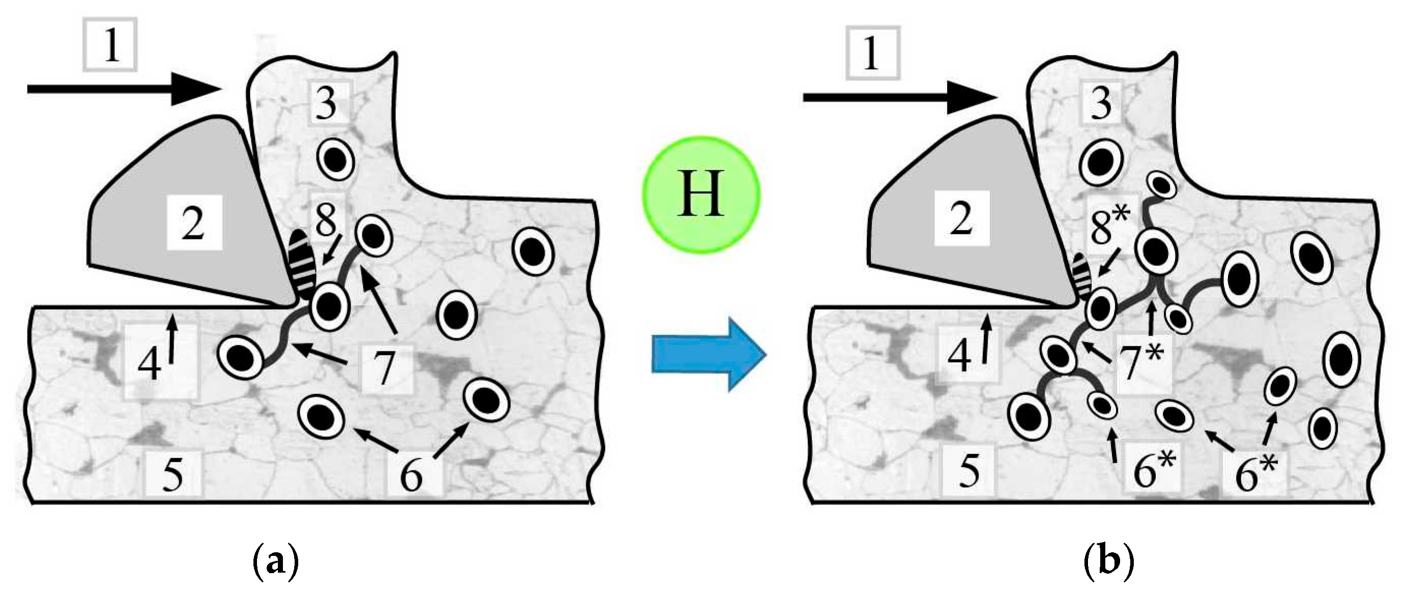


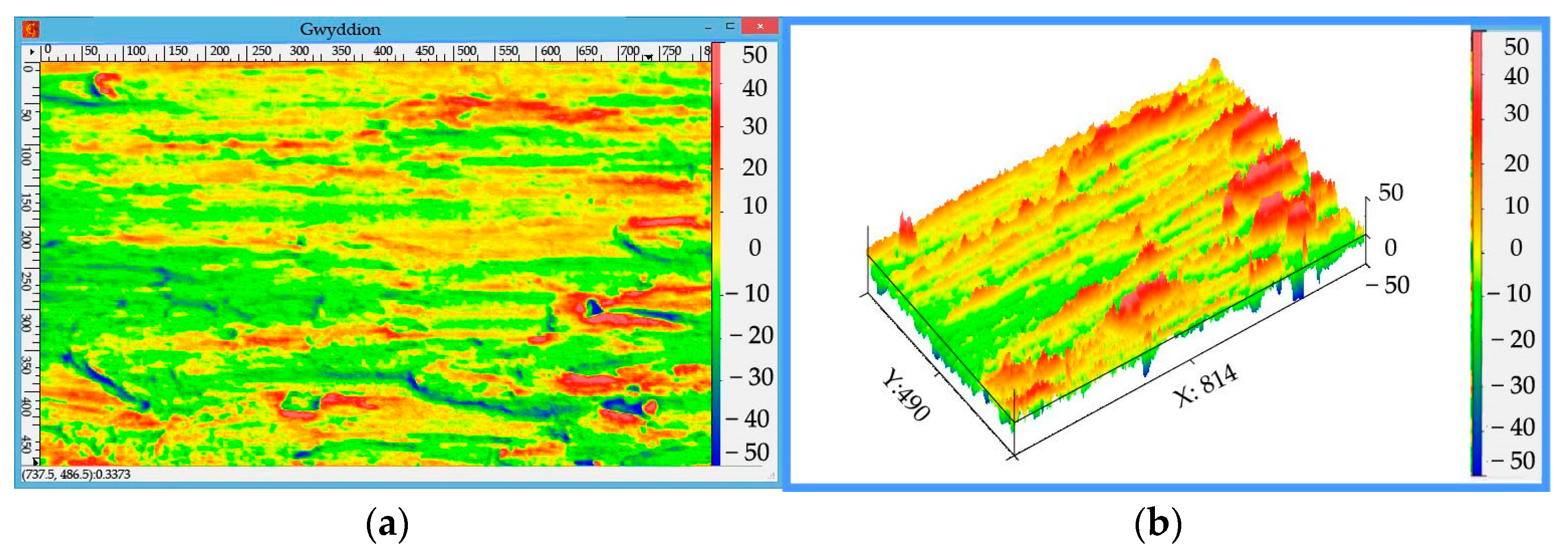
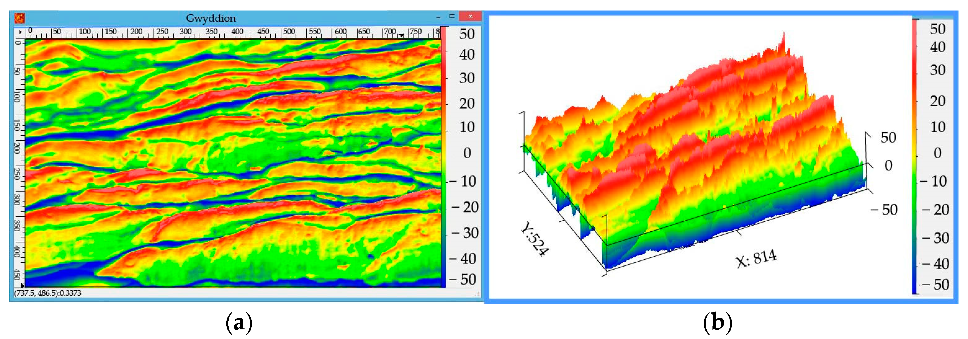
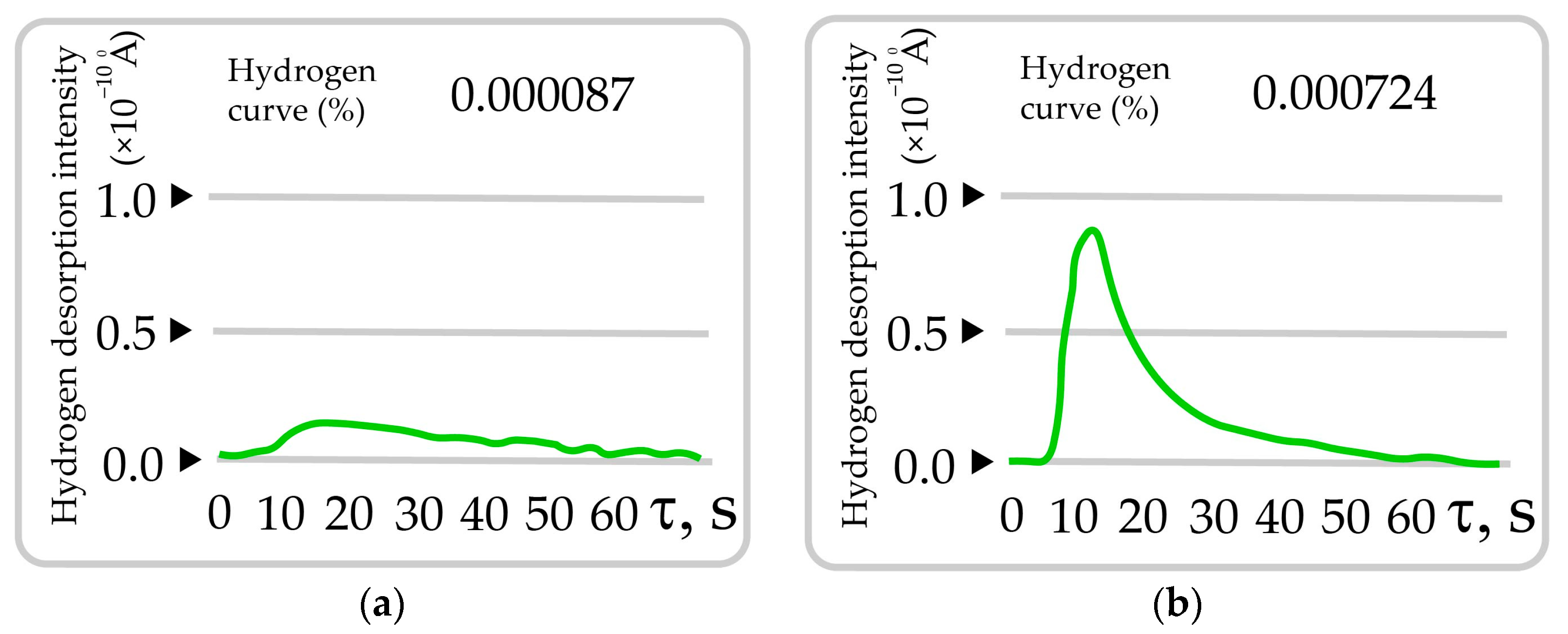

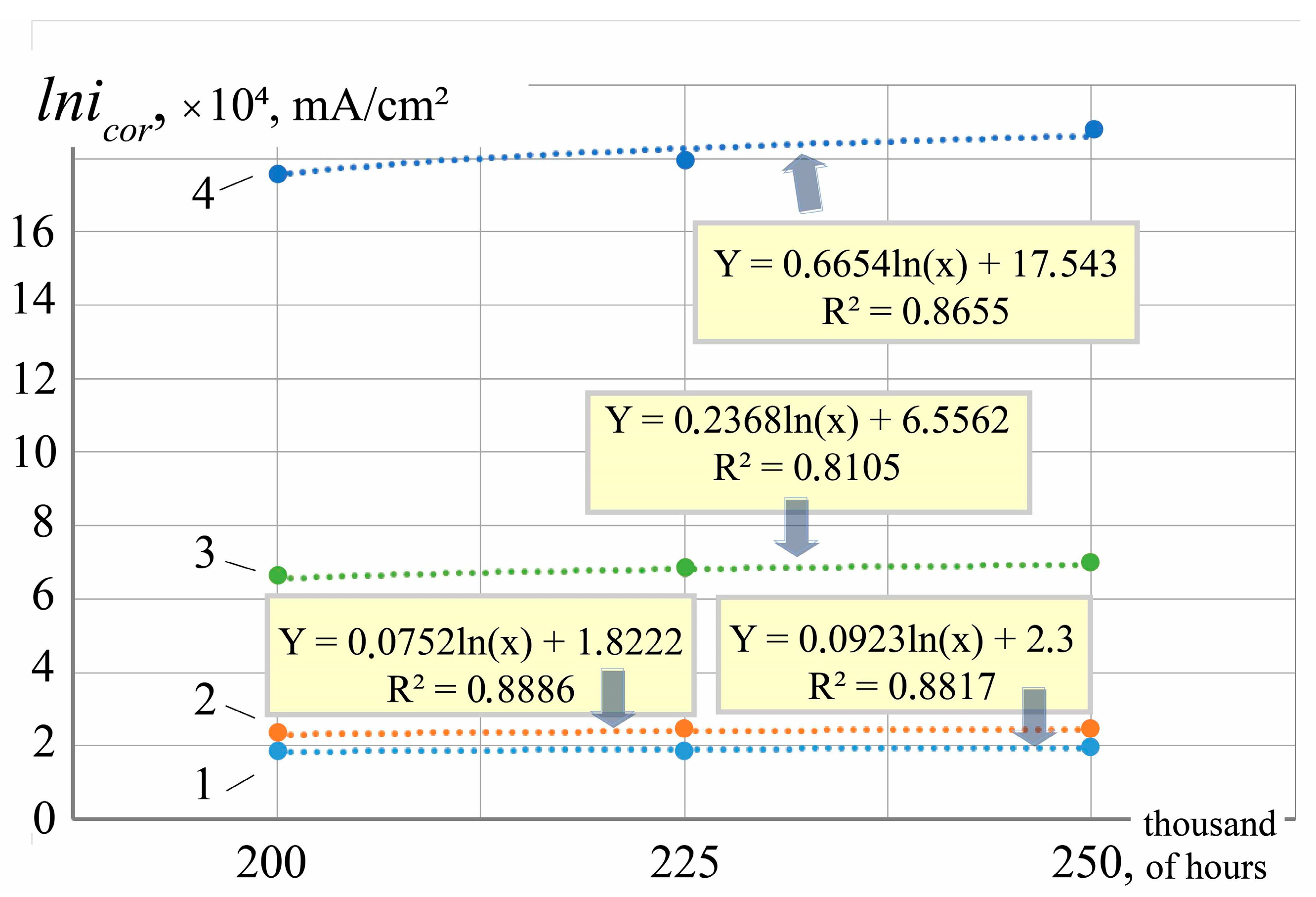
| Environment | icor,·104 mA/cm2 | Ecor, mV | icor,·104 mA/cm2 | Ecor, mV | icor,·104 mA/cm2 | Ecor, mV | icor,·104 mA/cm2 | Ecor, mV |
|---|---|---|---|---|---|---|---|---|
| 1 | 2 | 3 | 4 | 5 | 6 | 7 | 8 | 9 |
| LCLs | 1.70 (100%) | −175 | 1.83 (8.12%) | −174 | 1.88 (10.61%) | −172 | 1.96 (15.44%) | −169 |
| LCLr | 2.14 (100%) | −179 | 2.31 (8.27%) | −178 | 2.37 (10.94%) | −176 | 2.47 (15.77%) | −173 |
| LCLp | 6.03 (100%) | −187 | 6.59 (9.35%) | −186 | 6.71 (11.33%) | −184 | 7.01 (16.39%) | −181 |
| Water | 16.02 (100%) | −325 | 17.62 (10.0%) | −324 | 18.03 (12.57%) | −322 | 18.78 (17.28%) | −319 |
| Environment | a (Slope) | b (Intercept) | R2 | p-Value | CI (a) |
|---|---|---|---|---|---|
| LCLs | 0.0752 | 1.8222 | 0.8886 | 0.012 | (0.03–0.12) |
| LCLr | 0.0923 | 2.3 | 0.8817 | 0.015 | (0.04–0.14) |
| LCLp | 0.2368 | 6.5562 | 0.8105 | 0.030 | (0.09–0.39) |
| Water | 0.6654 | 17.543 | 0.8655 | 0.010 | (0.32–1.01) |
| Method | Sensitivity to Early Damage | Hydrogen Detection | Spatial Resolution | Application | Remarks |
|---|---|---|---|---|---|
| Metallography (SEM/OM) | High | Indirect | ~1 μm | Laboratory | Reveals microcracks, carbide redistribution, inclusions |
| Fractography of chips | Medium | Indirect | ~1 μm | Field and lab | Useful for real-time wear/degradation trends |
| Hydrogen content in chips | High | Direct (ppm-level) | Local bulk | Lab | Requires sample prep; correlates with structural degradation |
| Electrochemical testing | Medium | Indirect | Macro (~mm) | Lab | Good for coolant evaluation and general corrosion resistance |
| Magnetic/eddy current tests | Medium | No | ~0.1–1 mm | Field | Detects discontinuities; limited for internal damage |
| Computer vision (chip wear) | Medium–High | No | Image resolution-based | Field and lab | Promising for automation and continuous monitoring |
Disclaimer/Publisher’s Note: The statements, opinions and data contained in all publications are solely those of the individual author(s) and contributor(s) and not of MDPI and/or the editor(s). MDPI and/or the editor(s) disclaim responsibility for any injury to people or property resulting from any ideas, methods, instructions or products referred to in the content. |
© 2025 by the authors. Licensee MDPI, Basel, Switzerland. This article is an open access article distributed under the terms and conditions of the Creative Commons Attribution (CC BY) license (https://creativecommons.org/licenses/by/4.0/).
Share and Cite
Balitskii, A.I.; Kolesnikov, V.O.; Havrilyuk, M.R.; Balitska, V.O.; Ripey, I.V.; Królikowski, M.A.; Pudlo, T.K. Steel Hydrogen-Induced Degradation Diagnostics for Turbo Aggregated Rotor Shaft Repair Technologies. Energies 2025, 18, 4368. https://doi.org/10.3390/en18164368
Balitskii AI, Kolesnikov VO, Havrilyuk MR, Balitska VO, Ripey IV, Królikowski MA, Pudlo TK. Steel Hydrogen-Induced Degradation Diagnostics for Turbo Aggregated Rotor Shaft Repair Technologies. Energies. 2025; 18(16):4368. https://doi.org/10.3390/en18164368
Chicago/Turabian StyleBalitskii, Alexander I., Valerii O. Kolesnikov, Maria R. Havrilyuk, Valentina O. Balitska, Igor V. Ripey, Marcin A. Królikowski, and Tomasz K. Pudlo. 2025. "Steel Hydrogen-Induced Degradation Diagnostics for Turbo Aggregated Rotor Shaft Repair Technologies" Energies 18, no. 16: 4368. https://doi.org/10.3390/en18164368
APA StyleBalitskii, A. I., Kolesnikov, V. O., Havrilyuk, M. R., Balitska, V. O., Ripey, I. V., Królikowski, M. A., & Pudlo, T. K. (2025). Steel Hydrogen-Induced Degradation Diagnostics for Turbo Aggregated Rotor Shaft Repair Technologies. Energies, 18(16), 4368. https://doi.org/10.3390/en18164368


