Article

Structure/Aerodynamic Nonlinear Dynamic Simulation Analysis of Long, Flexible Blade of Wind Turbine

1
Key Laboratory of High-Efficiency and Clean Mechanical Manufacture of MOE, School of Mechanical Engineering, Shandong University, Jinan 250061, China
2
State Key Laboratory of Advanced Equipment and Technology for Metal Forming, Shandong University, Jinan 250061, China
3
College of Shipbuilding Engineering, Harbin Engineering University, Harbin 150006, China
4
Institute of Engineering Thermophysics, Chinese Academy of Sciences, Beijing 100190, China
5
Goldwind Technology Co., Ltd., Beijing 100176, China
6
Department of Mechanical Engineering, Kyung Hee University, Yongin 17104, Republic of Korea
*
Authors to whom correspondence should be addressed.
Energies 2025, 18(16), 4362; https://doi.org/10.3390/en18164362
Submission received: 15 July 2025 / Revised: 7 August 2025 / Accepted: 14 August 2025 / Published: 15 August 2025

Abstract

To meet the requirements of geometric nonlinear modeling and bending–torsion coupling analysis of long, flexible offshore blades, this paper develops a high-precision engineering simplified model based on the Absolute Nodal Coordinate Formulation (ANCF). The model considers nonlinear variations in linear density, stiffness, and aerodynamic center along the blade span and enables efficient computation of 3D nonlinear deformation using 1D beam elements. Material and structural function equations are established based on actual 2D airfoil sections, and the chord vector is obtained from leading and trailing edge coordinates to calculate the angle of attack and aerodynamic loads. Torsional stiffness data defined at the shear center is corrected to the mass center using the axis shift theorem, ensuring a unified principal axis model. The proposed model is employed to simulate the dynamic behavior of wind turbine blades under both shutdown and operating conditions, and the results are compared to those obtained from the commercial software Bladed. Under shutdown conditions, the blade tip deformation error in the y-direction remains within 5% when subjected only to gravity, and within 8% when wind loads are applied perpendicular to the rotor plane. Under operating conditions, although simplified aerodynamic calculations, structural nonlinearity, and material property deviations introduce greater discrepancies, the x-direction deformation error remains within 15% across different wind speeds. These results confirm that the model maintains reasonable accuracy in capturing blade deformation characteristics and can provide useful support for early-stage dynamic analysis.

1. Introduction

With the transformation of the global energy structure to low carbonization, wind power generation, as one of the renewable energy technologies with the greatest potential for large-scale development, has received extensive attention for its equipment design and operation optimization. As the core component of energy capture, the dynamic characteristics of wind turbine blades directly affect the power generation efficiency, structural safety, and operational life of the unit [1]. However, as composite material blades increase in size and aerodynamic, inertial, and elastic forces strongly couple on the blades within complex wind fields, they exhibit significant instability phenomena such as large deformations and nonlinear vibrations [2,3,4]. The existing dynamic modeling methods have deficiencies in terms of efficiency and accuracy. Consequently, establishing an efficient and high-fidelity blade dynamics model for accurately predicting the dynamic response of blades has become a critical challenge in advancing the reliability and design standards of wind turbines.
Currently, the dynamic modeling of wind turbine blades primarily relies on two approaches: high-fidelity three-dimensional finite element models employing solid or shell elements, and simplified beam models based on beam elements. Among them, the three-dimensional finite element model can accurately represent the complex blade geometry and deliver high-precision dynamic response analysis results [5,6,7,8,9]. However, its substantial computational cost and intricate modeling process significantly limit its practical application. In contrast, beam models strike a favorable balance between computational efficiency and accuracy, and thus have become the most widely adopted approach for dynamic analysis. Typical beam models include the Euler–Bernoulli beam [10,11,12], the Timoshenko beam [13,14,15,16], and the geometrically exact beam [17,18,19,20,21], among others. The Euler–Bernoulli beam model neglects both shear deformation and torsional degrees of freedom, resulting in limited accuracy and underestimated deformation magnitudes [22,23]. The Timoshenko beam model accounts for shear deformation and provides more realistic deformation predictions; however, it exhibits limitations when addressing large deformations and finite cross-sectional rotations, and is more appropriate for short, thick beams [24,25,26]. The geometrically exact beam model, developed on the basis of Timoshenko theory, introduces rotational degrees of freedom to accurately capture large displacements, finite rotations, and geometric nonlinearities. It has demonstrated clear advantages in analyzing the nonlinear behavior of slender and flexible structures [25]. At present, there are many scholars who study the dynamic characteristics of wind turbine blades based on the geometric exact beam theory [27,28,29,30,31]. For instance, Wang et al. [32] proposed a three-dimensional nonlinear elastic deformation method based on the geometrically exact beam theory and the Legendre spectral finite element method, and analyzed the dynamic characteristics of the NREL 5-MW wind turbine blade. Based on the geometrically exact beam theory and multibody dynamics, Leng et al. [33] conducted both modal and transient analyses of a vertical axis wind turbine. Similarly, Wang et al. [34] developed an aeroelastic coupling model to investigate the dynamic response of iced blades based on the geometrically exact beam theory. Table 1 presents an overview of the above-mentioned commonly used methods, together with their associated software and representative references previously cited in this part.
In addition to the structural modeling approaches mentioned above, full aeroelastic testing methods [35,36,37,38,39] and modal analysis techniques [40,41,42,43] also play a significant role in studying the dynamic characteristics of wind turbine blades. For instance, Wu et al. [44] proposed a design method for the aeroelastic model of three-dimensional wind turbine blades with variable cross-sections, effectively addressing the scaling challenges associated with such blades. Based on this, they developed an aeroelastic wind tunnel testing method capable of accurately capturing the wind-induced vibration characteristics of piezoelectric blades. Furthermore, Wu et al. [45] introduced an efficient computational framework for the nonlinear dynamic modeling of blades by integrating an improved blade element momentum (BEM) theory and geometrically exact beam theory with the harmonic balance method. The accuracy and reliability of this framework were validated through fully aeroelastic wind tunnel experiments. Jiang et al. [46] investigated the phenomenon of modal localization in wind turbine blades and analyzed the effects of various detuning patterns on its occurrence. Amna et al. [47] explored the relationship between the rotational speed and the modal characteristics of the blade system.
The geometrically exact beam theory assumes an orthonormal cross-sectional frame, requiring rotation interpolation, which increases computational complexity and can cause singularities [48]. In contrast, the Absolute Nodal Coordinate Formulation (ANCF) replaces the orthogonal frame with a gradient field, directly describing element deformation using nodal positions and gradients in global coordinates. This avoids singularities and results in a constant mass matrix, improving computational efficiency [49,50,51]. ANCF effectively captures bending, axial deformation, and their coupling in flexible slender structures, making it well-suited for large deformations and finite rotations. Nada et al. [52] introduced a method to map B-spline surfaces onto ANCF plate elements and used a fixed cantilever blade to verify the method’s efficiency and accuracy. Bayoumy et al. [53] developed a similar model using ANCF plate elements, analyzing blades with different NACA profiles, and validating results against ANSYS. However, generating plate element nodes is time-consuming, and each blade geometry requires a separate configuration, limiting scalability. Moreover, the models by Nada and Bayoumy are simplified. Nada’s model excludes aerodynamic loads, while Bayoumy’s model applies them simplistically at the element’s center of mass, overlooking deviations caused by structural and material nonlinearities—potentially reducing accuracy.
In this study, a dynamic model for wind turbine blades is constructed by incorporating the actual blade’s material characteristics and geometry into the Absolute Nodal Coordinate Formulation (ANCF) for slender beams. An aerodynamic force calculation method for the airfoil section is derived, and the blade’s dynamic responses under both wind and non-wind conditions are examined. Compared to full 3D finite element models, it offers better computational efficiency; compared to geometrically exact beam theory, it avoids interpolation-related singularities. Additionally, unlike the ANCF plate element approaches of Nada and Bayoumy, this method fully incorporates aerodynamic loads and removes the need for reconfiguring mesh nodes for different blade geometries, enhancing its adaptability. To verify the model’s performance, the simulation results are compared to those from the commercial software GH Bladed V4.11, which is based on Timoshenko beam theory. The comparison shows that the proposed method is both accurate and practical for engineering analysis of large-scale blades.
This paper is organized into five sections. Following the introduction, Section 2 introduces the Absolute Nodal Coordinate Formulation (ANCF), outlining its theoretical knowledge—key formulations for mass, elastic, and external forces in slender beam elements. Section 3 explains the approach used to compute aerodynamic forces at the airfoil section. Section 4 builds the dynamic model and presents simulation results under various operating scenarios. Finally, Section 5 summarizes the main contents of this study, highlighting the effectiveness of the proposed modeling and simulation approach in capturing the nonlinear dynamic behavior of flexible blades.

2. Absolute Nodal Coordinate Formulation

The Absolute Nodal Coordinate Formulation (ANCF) describes the motion and deformation of beams using nodal displacement and gradient vectors. It is derived based on the constitutive model of continuum mechanics, which allows for the representation of shear deformation. When high-order beam elements are employed, the method can also capture the torsional deformation of beams with non-circular cross-sections. Given that wind turbine blades are much longer than their cross-sectional dimensions, they can be treated as slender structures for modeling purposes. Moreover, since torsional deformation is present in such blades, high-order beam elements are adopted in this study for accurate representation. The specific formulation of ANCF for slender bodies is detailed as follows.
A slender beam of uniform material with length L, as shown in Figure 1, can describe the position of any point p at time t as
r p ( x , y , z , t ) = r ( x , t ) + y r y ( x , t ) + z r z ( x , t )
r ( x , t ) = s α ( x ) q α ( t ) r y ( x , t ) = y α ( x ) q α ( t ) r z ( x , t ) = z α ( x ) q α ( t ) α = 1 , 2 , 3 , 10
where r ( x , t ) represents the centroid line function related to x of the beam arc length coordinate; r y ( x , t ) and r z ( x , t ) denotes the two directional vectors of the beam section, which form a coordinate system; and the corresponding coordinates of point p in this frame is ( y , z ) . In Equation (2), s α ( x ) , y α ( x ) , z α ( x ) are the interpolation shape functions, and q α is the generalized coordinates of the element node.
q 1 = r ( x n 1 , t ) q 6 = r z ( x n 1 2 , t ) q 2 = r x ( x n 1 , t ) q 7 = r ( x n , t ) q 3 = r y ( x n 1 , t ) q 8 = r x ( x n , t ) q 4 = r z ( x n 1 , t ) q 9 = r y ( x n , t ) q 5 = r y ( x n 1 2 , t ) q 10 = r z ( x n , t )
s 1 = 1 3 ξ 2 + 2 ξ 3 s 2 = l n ( ξ 2 ξ 2 + ξ 3 ) y 3 = z 4 = 1 3 ξ + 2 ξ 2 y 5 = z 6 = 4 ξ ( 1 ξ ) s 7 = 3 ξ 2 2 ξ 3 s 8 = l n ( ξ 3 ξ 2 ) y 9 = z 10 = ξ ( 2 ξ 1 )
In Equation (3), x n 1 2 = ( x n 1 + x n ) / 2 represents the midpoint coordinate of element n, x n 1 is the left endpoint coordinate of element n, and x n is the right. In Equation (4), ξ is the normalized arc length coordinate in the element, and ξ = ( x x n 1 ) / l n , l n is the length of the beam element; here, only the nonzero terms of the shape function are listed.
When the beam material is uniform, the centroid line passes through the center of each cross-section. According to the kinetic energy theorem, the kinetic energy of the nth element is given by
K n = x n 1 x n ρ A r ˙ r ˙ + J y y r ˙ y r ˙ y + J z z r ˙ z r ˙ z + J y z r ˙ y r ˙ z d r d r = G ^ d x   ,   G = r x , r y , r z T
where G is the frame field of the center of gravity of the beam section. The superscript symbol ^ denotes the reference configuration, and the superscript · denotes the derivative of the function with respect to time t. ρ A denotes the linear density distribution of the beam element along the centroid-line arc-length coordinate x , while J y y , J z z , J y z represents the sectional mass moment of inertia function along the same coordinate.
For Equation (2), the first derivative with respect to time t can be obtained:
r ˙ = s α q ˙ α , r ˙ y = y α q ˙ α , r ˙ z = z α q ˙ α
Then bring it into Equation (5) to obtain the kinetic energy:
K n = 1 2 m n α β q ˙ α T q ˙ β
The mass matrix at this element is m n α β I 3 , I 3 is a 3-order unit matrix [50], and α , β = 1 , 2 , 3 , , 10 .
m n α β = x n 1 x n ρ A s α s β + J y y y α y β J y z y α z β + z α y β + J z z z α z β d r
The variation in elastic potential energy at the nth element of a slender beam can be expressed by the virtual work of elastic force:
δ U n = δ q α q β k n α β μ ν 1 2 q μ q ν + c q μ q ˙ ν k ^ n α β
According to Equation (9), the generalized elastic force of this blade element can be obtained:
F e α = k n α β μ ν 1 2 q μ q ν + c q μ q ˙ ν k ^ n α β q β
The corresponding generalized elastic force Jacobian matrix is
F e α q β = k n α β μ ν 1 2 q μ q ν + c q μ q ˙ ν k ^ n α β I 3 + k n α β μ ν q μ q ν + c q ˙ ν T F e α q ˙ β = c k n α β μ ν q μ ( q ν ) T
where k n α β μ ν is the constant coefficient tensor, k ^ n α β = 1 / 2 k n α β μ ν q ^ μ q ^ ν , c is the viscoelastic damping coefficient.
k n α β μ ν = x n 1 x n E b α β T C E b μ ν + E c α β T C W E c μ ν + K y α β T C y y K y μ ν + K z α β T C z z K z μ ν d r
where C , C W , C y y , C z z is the stiffness parameter function of the beam element along the arc length coordinate x of the centroid line.
K y α β = s x α y β + y α s x β y α y β + y α y β z α y β + y α z β K z α β = s x α z β + z α s x β y α z β + z α y β z α z β + z α z β E b α β = s x α s x β s x α y β + y α s x β s x α z β + z α s x β E c α β = y α y β z α z β y α z β + y β z α
In Equation (13), the subscript x represents the partial derivative of the shape function with respect to x . y α and z α are defined as shown in Equation (14), and k y and k z are curvature-like vectors related to bending and torsion.
y α = y x α s x α y α z α k ^ y , z α = z x α s x α y α z α k ^ z
k y = r x y ( r y × r z ) r x ( r y × r z ) , r x y ( r z × r x ) r y ( r z × r x ) , r x y ( r x × r y ) r z ( r x × r y ) T k z = r x z ( r y × r z ) r x ( r y × r z ) , r x z ( r z × r x ) r y ( r z × r x ) , r x z ( r x × r y ) r z ( r x × r y ) T
Along the centroid line of the beam element, there are often distributed forces and distributed moments. According to the principle of virtual work, the virtual work performed by the distributed force and distributed moment at the nth element is
δ W n = x n 1 x n δ r ( x , t ) f ( x , t ) + δ Π ( x , t ) t ( x , t ) d r δ Π ( x , t ) = 1 2 s x α s x β + y α y β + z α z β q α ( t ) × δ q β ( t ) δ r ( x , t ) = s α δ q α ( t )
where f ( x , t ) and t ( x , t ) are the distributed force and distributed moment of the beam element along the arc length coordinate x of the centroid line. δ r ( x , t ) is virtual displacement, and δ Π ( x , t ) is an infinitesimal change in orientation. Therefore, according to Equation (16), the generalized external force at the element can be solved:
F f α = x n 1 x n s α f ( x , t ) d r 1 2 x n 1 x n s x α s x β + y α y β + z α z β t ( x , t ) d r × q β
By assembling the mass matrix, generalized elastic force matrix, and generalized external force matrix of each element, the global mass matrix and generalized force matrix of the entire slender beam model can be obtained. After applying the constraint equations Φ , the motion equation of the slender beam model in the ANCF is given by
M q ¨ + Φ q T λ = Q ( q , q ˙ , t ) Φ ( q , t ) = 0
where λ is the Lagrange multiplier, Q is the sum of the generalized elastic force and the generalized external force, and Φ q represents the constrained Jacobian matrix.

3. Aerodynamic Characteristics of Wind Turbine Blades

To account for energy losses within the flow tube and the modeling inaccuracies associated with classical blade element momentum (BEM) theory, appropriate corrections to the aerodynamic forces are required.
Assuming an incoming wind speed of V at infinity and neglecting loss effects, the relative velocity between the freestream and the leading edge of the blade airfoil can be expressed as
V ¯ r e l = V r ˙ l e
Building on the previous derivation, the relative velocity is projected onto the axial and tangential directions. The resulting components are used to determine the induced velocity, thereby yielding the corrected expression for the relative velocity:
V N = V ¯ r e l T e N , V T = V ¯ r e l T e ω V i n d u c e = a V N e N + a V T e ω V r e l = V ¯ r e l + V i n d u c e
where V i n d u c e is the induced velocity and V r e l is the corrected three-dimensional relative velocity; substituting V r e l into Equation (21) yields the relative velocity on the two-dimensional airfoil section. The parameters a and a denote the axial and tangential induction factors, respectively [54]. Meanwhile, e N = 1 , 0 , 0 T , P T = I 3 e N e N T , r = P T r l e , and e ω = ( r × e N ) / r .
To determine the angle of attack, the relative velocity must be projected onto the local airfoil section. The angle of attack is evaluated within a two-dimensional coordinate frame r y , r z T defined at the airfoil section, so the incoming flow velocity in this frame can be expressed as
V b e = G E 3 G 1 V r e l
where E 3 = d i a g ( 0 , 1 , 1 ) .
The chord length vector on the airfoil section extends from the leading edge to the trailing edge, and its vector expression in the frame G is
c x = y t e y l e r y + z t e z l e r z
where y t e , y l e , z t e , z l e denote the coordinates of the leading and trailing edge of the airfoil section in the section’s local coordinate system.
To address the inaccuracies introduced by the assumptions in classical blade element momentum (BEM) theory, Prandtl’s tip and hub loss factors are applied to account for three-dimensional flow effects near the blade root and tip. Furthermore, since BEM theory is no longer valid under high axial induction conditions, the Glauert correction—formulated by Spera for wind turbine applications—is incorporated to improve the accuracy of thrust and torque predictions for blade elements [55].
d T = B p N d r = 4 π r ρ V N 2 a 1 a F d r a a c 4 π r ρ V N 2 a c 2 + 1 2 a c a F d r a > a c
d M = r B p T d r = 4 π r 2 ρ V N V T 1 a a F d r
where T denotes the thrust, M the torque, B the number of blades, F the Prandtl tip/hub loss factor, r the radial position of the blade element measured from the hub center, and p N and p T the thrust and tangential force per unit length acting on the blade element, respectively. The constant threshold of the axial induction factor is a c = 0.2 .
F = F t i p F r o o t F t i p = 2 π a r c c o s e x p B R t i p r 2 r s i n φ F r o o t = 2 π a r c c o s e x p B r R h u b 2 r s i n φ
where R t i p is the blade length, R h u b is the hub radius, and F t i p and F r o o t correspond to the tip loss factor and hub loss factor, respectively. The angle φ , known as the inflow angle, is defined as the angle between the relative velocity vector and the rotational plane of the impeller.
Based on the corrected relative velocity, the angle of attack for the blade section is calculated, as presented in Equation (26):
α = arctan 2 V b e × c e b e , V b e e b e
The corresponding aerodynamic coefficients are obtained by interpolating the airfoil aerodynamic database based on it. Subsequently, the aerodynamic coefficients at this section are used in the force calculation formulas to determine the aerodynamic loads.
f a e r o = 1 2 ρ c C L D V b e V b e τ = 1 2 ρ c 2 C M x , α V b e 2 e b e + τ f
where C L D = e ˜ b e + e b e e b e T C L + I 3 C D ,   e b e = r × r y / r z × r y , c is the norm of the chord vector. τ f is the translational moment generated when the aerodynamic force is translated to the center of mass. C L , C D , and C M are, respectively, the drag coefficient, lift coefficient, and moment coefficient.
The axial and tangential components of the aerodynamic force are calculated based on the above formula:
p N = f a e r o e N ,   p T = f a e r o e T
Substituting Equation (28) into Equations (23) and (24) yields the following result:
( B c / 2 π r ) C L D V b e V b e e N = 4 V N 2 a 1 a F a a c 4 V N 2 a c 2 + 1 2 a c a F a > a c ( B c / 2 π r ) C L D V b e V b e e T = 4 V N V T 1 a a F
Within each time step of the aeroelastic solution for each blade element, the induction factors ( a and a ) are obtained through an iterative procedure, and the corresponding aerodynamic force and torque are continuously updated accordingly.

4. Simulation and Results

Based on the Absolute Nodal Coordinate Formulation (ANCF) and the aerodynamic load model, a blade dynamic model was established, and a MATLAB 2024b program was developed to analyze the blade’s dynamic characteristics. The blade model used in this study has a total length of 78.3 m and a root diameter of 2.9 m. The complete model data was provided by a cooperator who developed the blade using the GH Bladed software. As the information about this blade is not made public for the time being, the blade’s partial parameter information is presented in Table 2.
Since in GH Bladed the material property parameters of the blade, such as axial stiffness and torsional stiffness, are defined based on local coordinate systems at each cross-section, which differs from the ANCF beam element formulation where all material properties are concentrated along the centerline reference frame, it is necessary to perform appropriate parameter equivalence processing when converting these data for use in the ANCF model.
In the material properties, the bending stiffness (EI) and shear stiffness (GA) are defined along the material principal axes, with the origin located at the center of mass, and no coupling terms are included. The torsional stiffness (GJ) is defined at the shear center and must be corrected to the centroid using the parallel axis theorem:
G J c m = G J s c + G A y y e z 2 + G A z z e y 2
In Equation (30), G represents the shear modulus; J c m and J s c denote the polar moments of inertia about the center of mass and the shear center, respectively, with respect to the torsional axis; and G J c m represents the torsional stiffness relative to the center of mass. A y y and A z z are the projection areas of the blade airfoil onto the y-axis and z-axis, respectively. e y and e z represent the eccentricities of the shear center relative to the center of mass along the y-direction and z-direction.
Using the radius of gyration ratio k, the torsional stiffness along the two principal axes can be estimated as follows:
G J y y = G J c m 1 + k 2 ,   G J z z = k 2 G J c m 1 + k 2
Similarly, for the inertial parameters, the sectional moments of inertia along the two principal axes can be calculated from the polar moment of inertia and the radius of gyration ratio:
J y y = J c m 1 + k 2 ,   J z z = k 2 J c m 1 + k 2
It is worth noting that, since the blade’s material properties are defined with respect to the local coordinate system at each cross-section, the simplified application of the axis-shift theorem used here mainly aims to account for the effect of the offset between the shear center and the centroid of the cross-section. However, this will bring certain material property errors, which will be specifically discussed in the actual simulation results later.

4.1. Model Simulation Settings

4.1.1. Construction of Constraint Equations

Each wind turbine blade is modeled as a cantilever beam mounted on the central rotating shaft. An additional rotational degree of freedom, θ, is introduced, and each blade is subject to a corresponding constraint equation:
Φ = r A r 0 r x A r x 0 r y A r y 0 r z A r z 0 ,   A = 1 0 0 0 cos θ sin θ 0 sin θ cos θ
When the turbine is stationary, the constraint equation θ = 0 is applied; when a rotational speed is specified, the constraint is defined as θ = ω t .
After introducing the additional rotational degrees of freedom, the final form of the generalized coordinates is
q = q 1 , q 2 , q 3 , θ
where q i , i = 1 , 2 , 3 represents the generalized coordinate vector associated with the ith blade.

4.1.2. Working Condition Settings and Model Simulation Parameters

The simulation parameters of the model were set as follows: hub radius of 1.792 m and air density of 1.225 kg/m3. To ensure consistency in the subsequent comparison with the GH Bladed simulation results, the blade was discretized into 80 elements, matching the configuration used in Bladed. The model was validated under both parked and operational conditions, where the parked condition included two scenarios: with wind load and without wind load. The detailed description of the simulation conditions is provided below.
(1) Under shutdown conditions, no wind load is applied to the wind turbine blade. One of the blades is positioned horizontally. In this state, the blade is subjected only to gravitational loading. By varying the pitch angle at intervals of 10°, the deformation of the blade tip under different pitch angles was simulated and analyzed.
(2) The blades are exposed to a uniform incoming wind velocity of 10 m/s, and various pitch angles are applied. Figure 2 illustrates the force distribution acting on the blade when the pitch angle is set to 0°.
(3) The operating conditions of the wind turbine are defined as follows: the pitch angle is set to 0°, and the rotational speed is 13 revolutions per minute (rpm). The wind speed and other relevant parameters are listed in Table 3. Additionally, the wind speed and the initial spatial configuration of the wind turbine are illustrated in Figure 3. At the initial state, Blade 1 is positioned horizontally, while Blades 2 and 3 are arranged in a clockwise orientation relative to Blade 1.

4.2. Comparison of Simulation Results of Blade Operating Conditions

4.2.1. Condition 1: Horizontal Shutdown Condition Under Self-Weight

The displacement of the tip and the midpoint of the blade is presented in Figure 4. In this figure, the displacement in the x-direction represents the deformation perpendicular to the blade’s rotational plane, while the displacements in the y- and z-directions lie within the rotational plane, with the z-direction aligned with the blade’s spanwise (axial) extension.
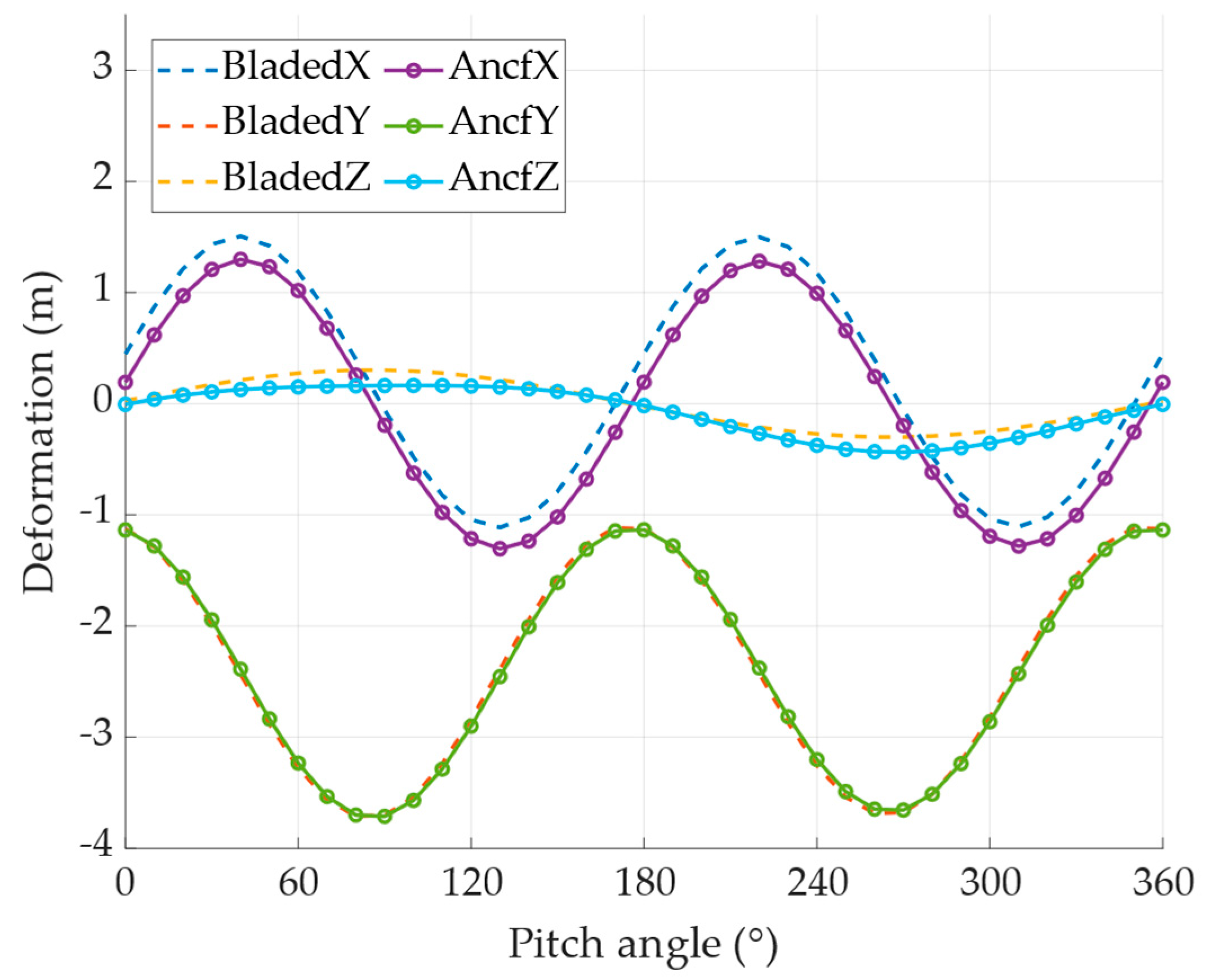
Figure 5 compares the blade tip deformations in the x- and y-directions under different pitch angles. The dotted line represents the simulation results from Bladed, while the line with circular markers corresponds to those from the ANCF-based dynamic model. Due to the modification of torsional stiffness, certain discrepancies arise. However, under shutdown conditions, the deformations in the x- and z-directions are relatively small compared to the y-direction, and thus the analysis primarily focuses on the y-direction deformation. Figure 6 provides a comparative visualization of the blade’s geometry before and after deformation along the y-axis. The initial undeformed shape is indicated by the solid line, whereas the deformed configuration is depicted using a dotted line, and the pitch angle here is 0.
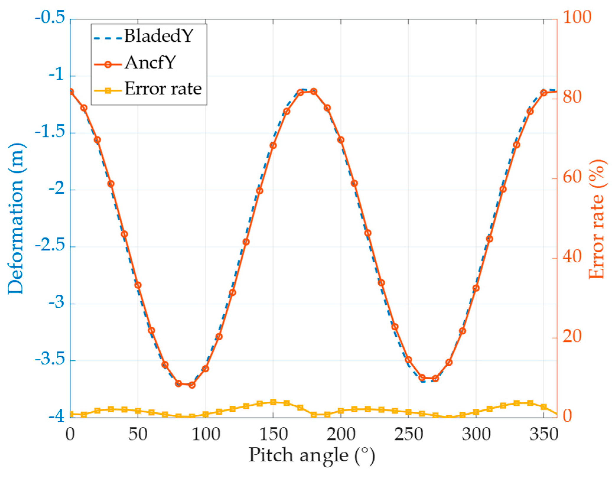
The y-direction deformation predicted by the dynamic model is slightly smaller than that of the Bladed simulation, but the values are very close. The deformation errors in the y-direction across various pitch angles are illustrated in Figure 7, further confirming the good agreement between the dynamic model and the commercial simulation results.

4.2.2. Condition 2: Horizontal Shutdown Condition Under Wind Load and Gravity

When the blade is stationary, under this wind loading, the blade experiences increased deformation primarily in the x-direction. As shown in Figure 8, the x-direction deformation predicted by the dynamic model exhibits a noticeable discrepancy compared to the results from Bladed. This difference is primarily attributed to the correction of torsional stiffness in the dynamic model, which was implemented through axis shifting, leading to deviations in the material properties. Similarly, Figure 9 provides a comparative visualization of the blade’s geometry before and after deformation along the y-axis.
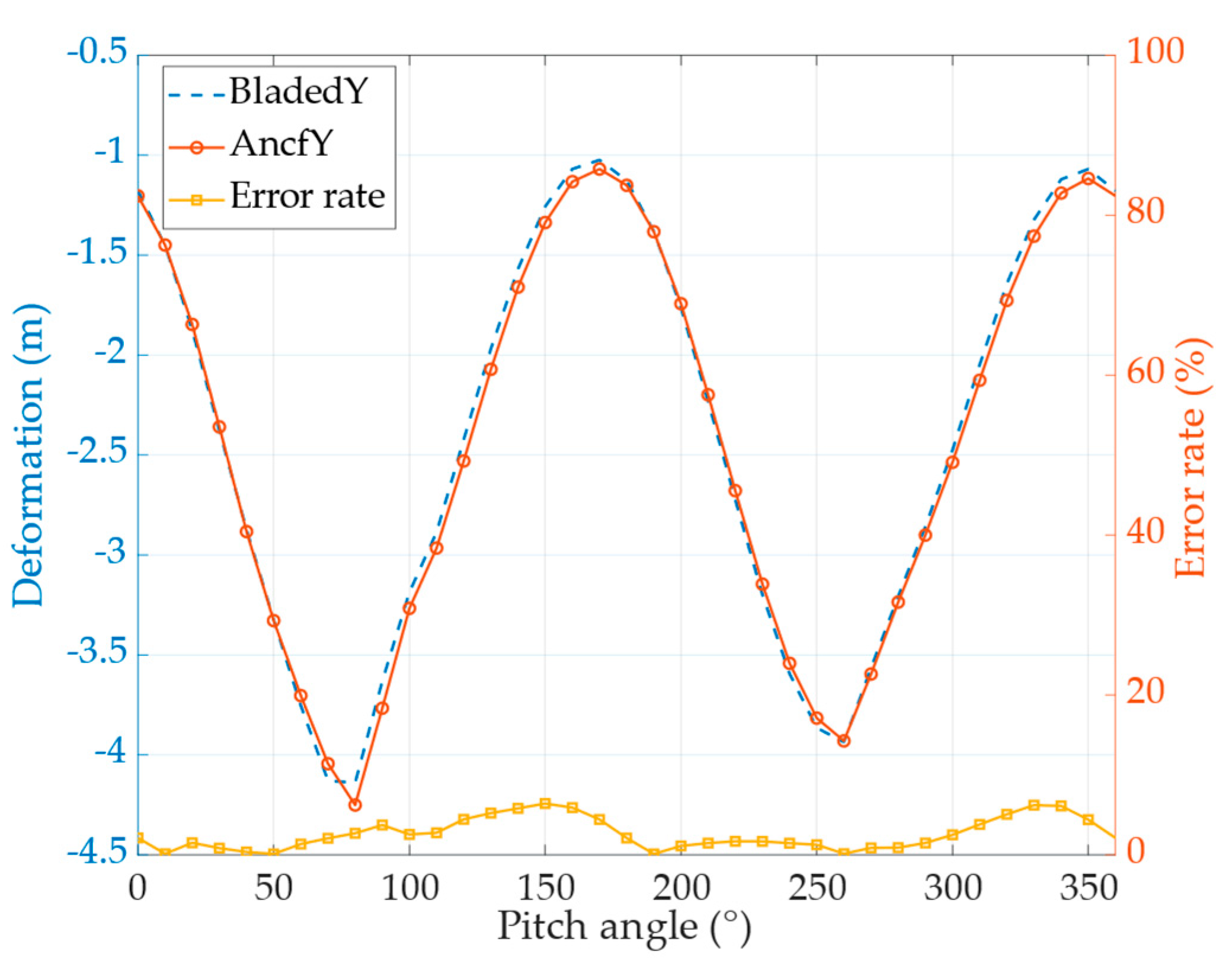
Meanwhile, a slight difference in y-direction deformation is also observed under wind loading, as illustrated in Figure 10. Due to the modified material properties, the error between the two models under wind loading is larger than that observed under windless conditions. Nevertheless, the deviations between the simulation results obtained from the ANCF-based blade model and those from Bladed remain within 8%, indicating a generally good agreement between the two approaches.

4.2.3. Condition 3: Operation Condition Under Wind Load and Gravity

Under operational conditions, the blade undergoes an initial acceleration phase, during which its rotational speed increases from zero to a steady-state value. The dynamic response of a single blade at a wind speed of 10 m/s is presented in Figure 11. The corresponding time histories of rotational speed, angular velocity, and angular acceleration are illustrated in Figure 12. The deformation of the blade under operating conditions is periodic. According to the provisions of the blade deformation in Bladed, the deformation at the position where the blade is vertically upward, that is, opposite to the direction of gravity, is the blade deformation.
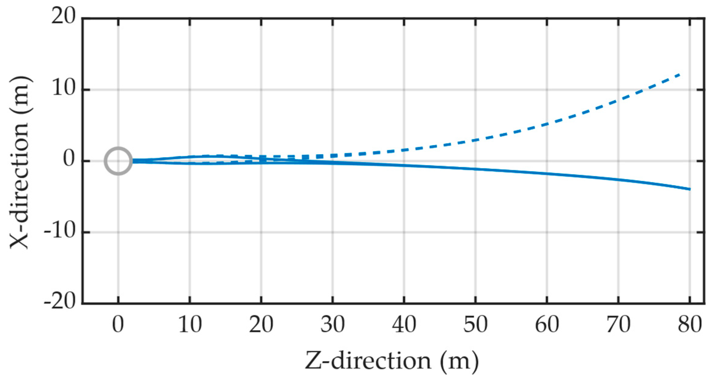
Figure 13 illustrates the comparative analysis of blade deformation in multiple directions, as computed by the proposed dynamic model under varying wind speeds, against the results obtained from the software Bladed. Figure 14 presents a comparison of the blade’s shape before and after deformation along the x-direction. Notably, the deformed shape corresponds to the blade’s configuration during its final passage through this position in the simulation timeframe. In Figure 13, the blade deformations in each direction predicted by the dynamic model exhibit noticeable discrepancies compared to the simulation results obtained from the Bladed software. This deviation primarily arises from simplifications made during the solution process of the dynamic model. Specifically, a constant initial-state induction factor was used throughout the aerodynamic calculations, resulting in reduced accuracy of the computed aerodynamic forces and, consequently, the deformation responses. Furthermore, the significant geometric nonlinearity of the blade structure and the axial-shift correction applied to the material properties lead to substantial variations in deformation under different wind speeds. Notably, under operating conditions, the deformation in the x-direction is greater than that in the other two directions. A comparison of the deformation magnitudes and the corresponding error rates is presented in Figure 15, where the deviation between the dynamic model and the Bladed simulation results remains within 15%. Despite the aforementioned influencing factors, the dynamic blade model developed in this study demonstrates good overall agreement with the results generated by the commercial Bladed software.

5. Discussion

This study verifies and discusses the modeling and aerodynamic response analysis of wind turbine blades under three typical working conditions: parked without wind, parked with wind, and operational. Under the parked without wind condition, where only gravitational loads are considered, the simulation results primarily reflect the accuracy of the structural modeling itself. The blade model used in this study was provided by a partner organization and designed based on GH Bladed. Its material parameters, such as axial and torsional stiffness, are defined with respect to different sectional coordinate systems, unlike the ANCF beam element, which assumes a centerline-based reference frame. To incorporate these parameters into the ANCF model, this study applies the parallel axis theorem to equivalently convert the torsional stiffness, accounting for the effect of the offset between the shear center and the centroid of the cross-section. Although this conversion inevitably introduces some material-related errors, under the parked without wind condition, the maximum discrepancy between the simulation results and Bladed, as shown in Figure 7, is within 5%, demonstrating high accuracy of the structural model under this condition. Under the parked with wind and operational conditions, aerodynamic loads have a significant influence on blade response. In this study, a simplified aerodynamic load computation is adopted, using a fixed initial induction factor without iterative correction. While this approach improves computational efficiency, it compromises the accuracy of aerodynamic force prediction, thereby affecting the precision of deformation results. As shown in Figure 10, the deformation error at the blade tip is relatively large, highlighting the dominant role of aerodynamic force accuracy in determining the overall structural response. In particular, under the operational condition, the blade undergoes significant aeroelastic responses under complex loading, and nonlinear effects become more pronounced, further increasing the deviation between simulation results and reference values. At typical wind speeds, the maximum deformation error reaches up to 15%, as shown in Figure 15. This indicates that although the current ANCF model demonstrates good consistency in structural modeling, the accuracy of aerodynamic modeling under wind loading remains a critical limiting factor for the overall simulation accuracy.

6. Conclusions

In this paper, a high-precision engineering simplified model that accounts for the geometric nonlinearity of wind turbine blades is developed based on the Absolute Nodal Coordinate Formulation (ANCF). The proposed method comprehensively considers structural and material nonlinearities along the spanwise direction of the blade and enables efficient computation of the three-dimensional nonlinear deformation of long and flexible blades using one-dimensional beam elements. Finally, the proposed dynamic model is applied to simulate representative operating conditions for validation and analysis.
(1)
The results under shutdown conditions demonstrate that the dynamic model and aerodynamic load calculation method based on the Absolute Nodal Coordinate Formulation (ANCF) can accurately capture the nonlinear deformation behavior of wind turbine blades. (a). In the absence of wind load, the horizontally positioned shutdown blade is subjected solely to gravitational forces. The tip displacements computed at various pitch angles show good agreement with the results from the commercial software Bladed, with errors remaining within 5%. (b). Under wind loading, the correction of torsional stiffness through axis shifting introduces local errors whose influence becomes significant, resulting in a slightly larger discrepancy in the x-direction deformation compared to the Bladed results. The y-direction deformation error remains within 8%, indicating acceptable accuracy of the proposed model.
(2)
Under operating conditions, the aerodynamic force computed by the dynamic model is subject to reduced accuracy due to the use of simplified methods in the aerodynamic solution process. Additionally, the strong geometric nonlinearity of the blade structure, combined with the axial-shift correction of material properties, introduces multiple sources of deviation. These factors collectively contribute to notable differences in blade deformation predicted by the dynamic model across various wind speeds when compared to the results generated by the Bladed software. Nevertheless, the error in the x-direction—where the blade experiences the largest deformation compared to the other two directions—remains within 15%.
(3)
The proposed method proves to be both accurate and practical for the engineering-level analysis of large-scale wind turbine blades, providing a novel approach to blade dynamic modeling.
The blade dynamics model established in this study has demonstrated its rationality and effectiveness under standard working conditions. Compared to models based on plate elements, it avoids the need to reconstruct element configurations for different blade geometries. This significantly improves modeling flexibility. In addition, thanks to the inherent advantages of the Absolute Nodal Coordinate Formulation (ANCF) in handling large deformations, large rotations, and strong nonlinear coupling, the model is particularly well-suited for analyzing the nonlinear deformation responses of ultra-long, flexible offshore blades under complex loading conditions such as wind, gravity, and centrifugal forces. Future research will aim to improve the accuracy of the aerodynamic calculation module in order to enhance the model’s ability to predict blade responses under complex and variable loading conditions. Meanwhile, the number of blade elements is further changed, and the variation trend of blade response with the number of elements is analyzed and compared to the results of the finite element software, thereby further improving the accuracy and convergence of the model. In addition, experimental data will be incorporated to validate the simulation results, further verifying the model’s engineering applicability and improving its reliability and practical value for real-world applications.

Author Contributions

Conceptualization, X.Z. and S.Y.; methodology, S.Y.; visualization, S.Y., Z.Y., and C.C.; writing—original draft, Z.Y.; writing—review and editing, X.Z. and S.Y.; validation, C.C. and Z.Y.; formal analysis, Z.Y.; supervision, X.Z.; investigation, J.-H.C. and L.Z.; project administration, L.Z. and Q.L.; resources, X.Z. and Q.L.; funding acquisition, X.Z., Q.L., and J.-H.C. All authors have read and agreed to the published version of the manuscript.

Funding

This research was funded by the National Key Research and Development Program of China (No. 2022YFE0207000), the Key Research and Development Program of Shandong Province (No. 2025CXGC010301), the National Natural Science Foundation of China (No. 1247020732), and the Fundamental Research funds for the Central Universities (No. 3072025CFJ0113).

Data Availability Statement

The original contributions presented in the study are included in this article, and further inquiries can be directed to the corresponding author.

Conflicts of Interest

Author Lei Zhang was employed by the Goldwind Technology Co., Ltd. The remaining authors declare that the research was conducted in the absence of any commercial or financial relationships that could be construed as a potential conflict of interest.

References

  1. Della Posta, G.; Leonardi, S.; Bernardini, M. A two-way coupling method for the study of aeroelastic effects in large wind turbines. Renew. Energy 2022, 190, 971–992. [Google Scholar] [CrossRef]
  2. Liu, T.; Cui, Q.; Xu, D. Wind Turbine Composite Blades: A Critical Review of Aeroelastic Modeling and Vibration Control. FDMP-Fluid Dyn. Mater. Process 2025, 21, 1–36. [Google Scholar] [CrossRef]
  3. Wang, Y.; Cai, C.; Liao, C.; Hu, Z.; Zhang, L.; Sun, X.; Zhong, X.; Li, Q. Aeroelastic stability analysis of large-scale wind turbine blades under different operating conditions based on system identification and Floquet theory. Energy 2025, 326, 136279. [Google Scholar] [CrossRef]
  4. Xu, J.; Zhang, L.; Li, X.; Li, S.; Yang, K. A study of dynamic response of a wind turbine blade based on the multi-body dynamics method. Renew. Energy 2020, 155, 358–368. [Google Scholar] [CrossRef]
  5. Navadeh, N.; Goroshko, I.O.; Zhuk, Y.A.; Etminan Moghadam, F.; Soleiman Fallah, A. Finite Element Analysis of Wind Turbine Blade Vibrations. Vibration 2021, 4, 310–322. [Google Scholar] [CrossRef]
  6. Chen, Y.; Zhou, S.; Cai, C.; Wang, W.; Hao, Y.; Zhou, T.; Wang, X.; Li, Q. Study on the Rotation Effect on the Modal Performance of Wind Turbine Blades. Energies 2023, 16, 1036. [Google Scholar] [CrossRef]
  7. Guo, S.X.; Li, Y.L.; Chen, W.M. Analysis on dynamic interaction between flexible bodies of large-sized wind turbine and its response to random wind loads. Renew. Energy 2021, 163, 123–137. [Google Scholar] [CrossRef]
  8. Abdullah, O.I.; Rakisheva, Z.B.; Jameel Al-Tamimi, A.N.; Majeed, M.H.; Khazem, E.A.; Schlattmann, J.; Mohammed, M.N.; Alfiras, M.; Alani, Z.N. Finite Element Analysis of Dynamic Behavior of NREL 5-MW Horizontal Axis Wind Turbine Blade. In Proceedings of the 2023 IEEE 8th International Conference on Engineering Technologies and Applied Sciences (ICETAS), Manama, Bahrain, 25–27 October 2023; pp. 1–6. [Google Scholar]
  9. Huang, H.S. Simulations of 10MW wind turbine under seismic loadings. Compos. Struct. 2022, 279, 114686. [Google Scholar] [CrossRef]
  10. Wang, Z.; Lu, Z.; Yi, W.; Hao, J.; Chen, Y. A study of nonlinear aeroelastic response of a long flexible blade for the horizontal axis wind turbine. Ocean Eng. 2023, 279, 113660. [Google Scholar] [CrossRef]
  11. Jiang, B.; Hui, Y.; Yang, Q.; Hua, X. Nonlinear dynamic analysis of parked large wind turbine blade considering harmonic inertial excitation using continuum mathematical model. Thin-Walled Struct. 2022, 181, 110128. [Google Scholar] [CrossRef]
  12. Arany, L.; Bhattacharya, S.; Adhikari, S.; Hogan, S.J.; Macdonald, J.H.G. An analytical model to predict the natural frequency of offshore wind turbines on three-spring flexible foundations using two different beam models. Soil Dyn. Earthq. Eng. 2015, 74, 40–45. [Google Scholar] [CrossRef]
  13. Yin, Y.; Liao, M.; Lyu, P. Analysis of Transient Response of Wind Turbine Blade Based Timoshenko Beam. Taiyangneng Xuebao/Acta Energiae Solaris Sin. 2017, 38, 2552–2558. [Google Scholar]
  14. Ma, H.; Lu, Y.; Wu, Z.; Tai, X.; Li, H.; Wen, B. A new dynamic model of rotor-blade systems. J. Sound Vib. 2015, 357, 168–194. [Google Scholar] [CrossRef]
  15. Otero, A.D.; Ponta, F.L. Structural Analysis of Wind-Turbine Blades by a Generalized Timoshenko Beam Model. J. Sol. Energy Eng. 2010, 132, 011015. [Google Scholar] [CrossRef]
  16. Zhou, X.; Huang, K.; Li, Z. Geometrically nonlinear beam analysis of composite wind turbine blades based on quadrature element method. Int. J. Non-Linear Mech. 2018, 104, 87–99. [Google Scholar] [CrossRef]
  17. Wang, Q.; Zhang, P.; Li, Y. Structural dynamic analysis of a tidal current turbine using geometrically exact beam theory. J. Offshore Mech. Arct. Eng. 2018, 140, 021903. [Google Scholar] [CrossRef]
  18. Leng, J.; Zhang, L.; Li, Y. Structural dynamic characteristics of vertical axis wind and tidal current turbines. Proc. R. Soc. A Math. Phys. Eng. Sci. 2024, 480, 20240234. [Google Scholar] [CrossRef]
  19. Rezaei, M.M.; Behzad, M.; Haddadpour, H.; Moradi, H. Aeroelastic analysis of a rotating wind turbine blade using a geometrically exact formulation. Nonlinear Dyn. 2017, 89, 2367–2392. [Google Scholar] [CrossRef]
  20. Saravia, C.M.; Gatti, C.D.; Ramirez, J.M. On the determination of the mechanical properties of wind turbine blades: Geometrical aspects of line based algorithms. Renew. Energy 2017, 105, 55–65. [Google Scholar] [CrossRef]
  21. Chen, J.; Shen, X.; Zhu, X.; Du, Z. Study on composite bend-twist coupled wind turbine blade for passive load mitigation. Compos. Struct. 2019, 213, 173–189. [Google Scholar] [CrossRef]
  22. Ma, X.; Peng, X.; Sun, J.; Chen, Y.; Huang, Z. A Comprehensive Investigation of Linear and Nonlinear Beam Models on Flexible Wind Turbine Blade Load Calculations. J. Mar. Sci. Eng. 2024, 12, 548. [Google Scholar] [CrossRef]
  23. Wan, C.; Hou, J.; Xue, S.; Zhang, G.; Xie, L.; Huang, G. Forced vibration of a novel beam model considering the shear deformation induced rotary inertia. Structures 2023, 47, 2541–2556. [Google Scholar] [CrossRef]
  24. Rangari, A.S.; Elishakoff, I.; Sarkar, K.; Amer Soc Mechanical, E. Slope-Inertia Model For Rotating Timoshenko-Ehrenfest Beams. In Proceedings of the ASME Aerospace Structures, Structural Dynamics, and Materials Conference (SSDM), San Diego, CA, USA, 19–21 June 2023. [Google Scholar]
  25. Panteli, A.N.; Manolas, D.I.; Riziotis, V.A.; Spiliopoulos, K.V. Comparative study of two geometrically non-linear beam approaches for the coupled wind turbine system. J. Wind Eng. Ind. Aerodyn. 2022, 231, 105231. [Google Scholar] [CrossRef]
  26. Tang, S.; Sweetman, B.; Gao, J. Nonlinear effects and dynamic coupling of floating offshore wind turbines using geometrically-exact blades and momentum-based methods. Ocean Eng. 2021, 229, 108866. [Google Scholar] [CrossRef]
  27. Wu, X.; Feng, K.; Li, Q. A Numerical Method for the Dynamics Analysis of Blade Fracture Faults in Wind Turbines Using Geometrically Exact Beam Theory and Its Validation. Energies 2024, 17, 824. [Google Scholar] [CrossRef]
  28. Lü, P.; Liao, M.; Xu, Y.; Yin, Y. Beam Finite Element for Wind Turbine Bladebased on Geometrically Exact Beam Theory. Acta Energiae Solaris Sin. 2015, 36, 2422–2428. [Google Scholar]
  29. Xiaohang, Q.; Zhiteng, G.; Tongguang, W.; Long, W.; Shitang, K. Nonlinear aeroelastic response analysis of 100-meter-scale flexible wind turbine blades. Acta Aerodyn. Sin. 2022, 40, 220–230. [Google Scholar]
  30. Chen, J.; Shen, X.; Liu, P.; Zhu, X.; Du, Z. Design tool for aeroelastic analysis of wind turbine blades based on geometrically exact beam theory and lifting surface method. In Proceedings of the 35th Wind Energy Symposium, Shanghai, China, 9–13 January 2017; p. 0450. [Google Scholar]
  31. Wang, L.; Liu, X.; Renevier, N.; Stables, M.; Hall, G.M. Nonlinear aeroelastic modelling for wind turbine blades based on blade element momentum theory and geometrically exact beam theory. Energy 2014, 76, 487–501. [Google Scholar] [CrossRef]
  32. Wang, Q.; Sprague, M.A.; Jonkman, J.; Johnson, N.; Jonkman, B. BeamDyn: A high-fidelity wind turbine blade solver in the FAST modular framework. Wind Energy 2017, 20, 1439–1462. [Google Scholar] [CrossRef]
  33. Leng, J.; Wang, Q.; Li, Y. A geometrically nonlinear analysis method for offshore renewable energy systems-Examples of offshore wind and wave devices. Ocean Eng. 2022, 250, 110930. [Google Scholar] [CrossRef]
  34. Wang, F.; Yang, Y.; Zeng, J.; Yang, Y. Research on dynamics of icing wind turbine blade based on geometrically exact beam theory. J. Sound Vib. 2025, 601, 118927. [Google Scholar] [CrossRef]
  35. Ren, H.; Weng, S.; Ke, S.; Zhao, K.; Tian, W. Investigation of wind-induced vibration evolution mechanisms in long-span flexible photovoltaic structures using three-dimensional digital image correlation method in aeroelastic wind tunnel tests. Phys. Fluids 2025, 37, 047126. [Google Scholar] [CrossRef]
  36. Lu, M.-m.; Ke, S.-t.; Wu, H.-x.; Tian, W.-x.; Wang, H.; Gao, M.-e. A novel forecasting method of flutter critical wind speed for the 15 MW wind turbine blade based on aeroelastic wind tunnel test. J. Wind. Eng. Ind. Aerodyn. 2022, 230, 105195. [Google Scholar] [CrossRef]
  37. Neunaber, I.; Danbon, F.; Soulier, A.; Voisin, D.; Guilmineau, E.; Delpech, P.; Courtine, S.; Taymans, C.; Braud, C. Wind tunnel study on natural instability of the normal force on a full-scale wind turbine blade section at Reynolds number 4.7 106. Wind Energy 2022, 25, 1332–1342. [Google Scholar] [CrossRef]
  38. Gao, R.; Yang, J.; Yang, H.; Wang, X. Wind-tunnel experimental study on aeroelastic response of flexible wind turbine blades under different wind conditions. Renew. Energy 2023, 219, 119539. [Google Scholar] [CrossRef]
  39. Wang, X.; Jiang, L.; Amjad, A.; Yang, H.; Yang, J. Experimental investigation on Aeroelastic response of long flexible blades in turbulent flow. Appl. Energy 2024, 375, 124109. [Google Scholar] [CrossRef]
  40. Maktouf, R.; Yangui, M.; Fakhfekh, T.; Nasri, R.; Haddar, M.A. Non-linear dynamic analysis of a wind turbine blade. J. Chin. Inst. Eng. 2019, 42, 727–737. [Google Scholar] [CrossRef]
  41. Zhao, X.; Jiang, X.; Zhu, W.; Li, J. Semi-analytical solutions for steady-state bending-bending coupled forced vibrations of a rotating wind turbine blade by means of Green’s functions. J. Sound Vib. 2025, 596, 118714. [Google Scholar] [CrossRef]
  42. Jokar, H.; Mahzoon, M.; Vatankhah, R. Nonlinear dynamic characteristics of horizontal-axis wind turbine blades including pre-twist. Ocean Eng. 2022, 256, 111441. [Google Scholar] [CrossRef]
  43. Jokar, H.; Vatankhah, R.; Mahzoon, M. Nonlinear super-harmonic and sub-harmonic resonance analysis of the horizontal-axis wind turbine blades using multiple scale method including the pre-twist effects. Ocean Eng. 2022, 265, 112610. [Google Scholar] [CrossRef]
  44. Wu, H.; Ke, S.; Lu, M.; Gao, M.; Tian, W.; Liu, D.; Li, Y.; Wang, T. Research on vibration suppression effect and energy dissipation mechanism of wind turbine piezoelectric blade. J. Fluids Struct. 2023, 117, 103814. [Google Scholar] [CrossRef]
  45. Wu, H.; Ke, S.; Ren, H.; Tian, W.; Wang, H.; Zhu, S.; Wang, T. An efficient reduced-order modeling framework for spatiotemporal aerodynamic damping in flexible wind turbine blades. Phys. Fluids 2025, 37, 055149. [Google Scholar] [CrossRef]
  46. Jiang, T.; Guo, X.; Zhang, Y.; Li, D. Study and Quantitative Analysis of Mode Localization in Wind Turbine Blades. J. Mar. Sci. Eng. 2024, 12, 67. [Google Scholar] [CrossRef]
  47. Algolfat, A.; Wang, W.; Albarbar, A. Study of Centrifugal Stiffening on the Free Vibrations and Dynamic Response of Offshore Wind Turbine Blades. Energies 2022, 15, 6120. [Google Scholar] [CrossRef]
  48. Fan, W.; Zhu, W.D. An accurate singularity-free geometrically exact beam formulation using Euler parameters. Nonlinear Dyn. 2018, 91, 1095–1112. [Google Scholar] [CrossRef]
  49. Shabana, A.A. An Absolute Nodal Coordinate Formulation for the Large Rotation and Deformation Analysis of Flexible Bodies; UIC Dynamic Simulation Laboratory: Chicago, IL, USA, 1996. [Google Scholar]
  50. Ren, H. A Simple Absolute Nodal Coordinate Formulation for Thin Beams With Large Deformations and Large Rotations. J. Comput. Nonlinear Dyn. 2015, 10, 061005. [Google Scholar] [CrossRef]
  51. Otsuka, K.; Makihara, K.; Sugiyama, H. Recent Advances in the Absolute Nodal Coordinate Formulation: Literature Review From 2012 to 2020. J. Comput. Nonlinear Dyn. 2022, 17, 080803. [Google Scholar] [CrossRef]
  52. Nada, A.A. Use of B-spline surface to model large-deformation continuum plates: Procedure and applications. Nonlinear Dyn. 2013, 72, 243–263. [Google Scholar] [CrossRef]
  53. Bayoumy, A.H.; Nada, A.A.; Megahed, S.M. A Continuum Based Three-Dimensional Modeling of Wind Turbine Blades. J. Comput. Nonlinear Dyn. 2013, 8, 031004. [Google Scholar] [CrossRef]
  54. Hansen, M. Aerodynamics of Wind Turbines; Routledge: London, UK, 2015. [Google Scholar]
  55. Ponta, F.L.; Otero, A.D.; Lago, L.I.; Rajan, A. Effects of rotor deformation in wind-turbine performance: The Dynamic Rotor Deformation Blade Element Momentum model (DRD-BEM). Renew. Energy 2016, 92, 157–170. [Google Scholar] [CrossRef]
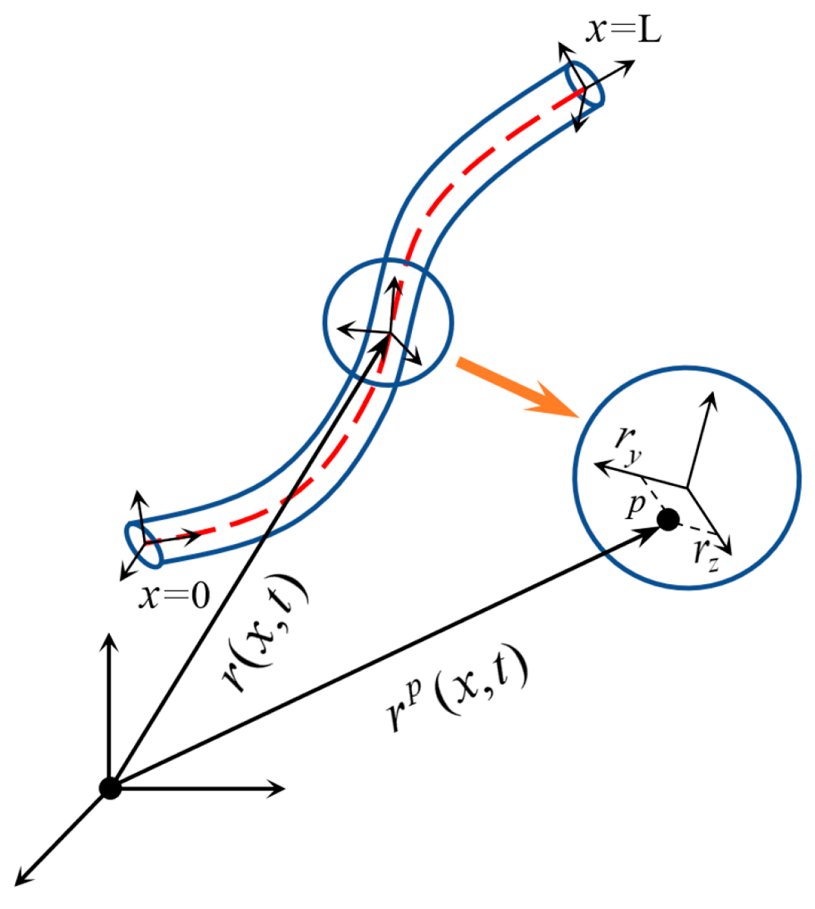
Figure 1. Slender beam absolute nodal coordinate frame diagram, the short red line is the center line of the beam.
Energies 18 04362 g001
Figure 2. Wind flow orientation around the wind turbine blade.
Energies 18 04362 g002
Figure 3. Wind flow orientation around the wind turbine [55].
Energies 18 04362 g003
Figure 4. The displacement of the blade tip and midpoint. (a) The displacement of the blade midpoint. (b) The displacement of the blade tip.
Energies 18 04362 g004
Figure 5. Tip displacements in x- and y-directions under various pitch angles.
Energies 18 04362 g005
Figure 6. Comparison of the undeformed and deformed blade configurations along the y-direction.
Energies 18 04362 g006
Figure 7. Comparison of y-direction deformation and error at the blade tip for different pitch angles.
Energies 18 04362 g007
Figure 8. Tip displacements in x- and y-directions at various pitch angles under the wind speed of 10 m/s.
Energies 18 04362 g008
Figure 9. Comparison of the undeformed and deformed blade configurations along the y-direction under the wind speed of 10 m/s.
Energies 18 04362 g009
Figure 10. Comparison of y-direction deformation and error at the blade tip for different pitch angles under the wind speed of 10 m/s.
Energies 18 04362 g010
Figure 11. The displacement of the blade tip and midpoint under a wind velocity of 10 m/s. (a) The displacement of the blade midpoint. (b) The displacement of the blade tip.
Energies 18 04362 g011
Figure 12. The speed variation in the wind turbine under a wind velocity of 10 m/s.
Energies 18 04362 g012
Figure 13. Blade deformation comparison under various operating conditions.
Energies 18 04362 g013
Figure 14. Comparison of the undeformed and deformed blade configurations along the x-direction.
Energies 18 04362 g014
Figure 15. Blade x-deformation comparison and error under various wind speeds.
Energies 18 04362 g015
Table 1. Summary of the characteristics of four methods.
MethodAccuracyEfficiencyRelevant LiteratureRelevant Software or Code
Solid or shell elements (FEM)HighLow [5,6,7,8,9]Ansys, Abaqus
Euler–Bernoulli beamLowHigh [10,11,12,22,23]OpenFAST, Bladed, Modelica
Timoshenko beamMediumHigh [13,14,15,16,24,25,26]OpenFAST, Bladed
Geometrically exact beamHighMedium [17,18,19,20,21,27,28,29,30,31,32,33,34]BEAMDyn
Table 2. Part of the sectional parameters of the blade.
NumberMass per Unit Length
kg/m
Polar Inertia per Unit Length
kgm
Bending Stiffness About z
Nm2
Bending Stiffness About y
Nm2
13338.7453717.804331,868 × 1053,306,347 × 104
2855.87891724.2391,646,356 × 1041,631,844 × 104
3529.81531038.6849,198,995 × 1038,925,694 × 103
4464.9871891.65667,225,307 × 1037,075,645 × 103
45151.579765.825339,218,432 × 1021,888,861 × 102
46159.88565.045218,620,131 × 1021,691,846 × 102
47142.21955.306138,088,488 × 1021,547,374 × 102
48135.428150.048847,424,591 × 1021,349,393 × 102
795.6883075.5037 × 10−2277,481.22839.561
800.25542825.632 × 10−627.607850.165301
Table 3. Operating parameters.
NumberHub Wind Speed [m/s]Rotor Speed [rpm]Pitch Angle [deg]
15.0130
25.5130
36.0130
46.5130
99.0130
109.5130
1411.5130
1512.0130
1612.5130
1713130
Disclaimer/Publisher’s Note: The statements, opinions and data contained in all publications are solely those of the individual author(s) and contributor(s) and not of MDPI and/or the editor(s). MDPI and/or the editor(s) disclaim responsibility for any injury to people or property resulting from any ideas, methods, instructions or products referred to in the content.