Article

DNS Study of Freely Propagating Turbulent Lean-Premixed Flames with Low-Temperature Chemistry in the Broken Reaction Zone Regime

1
Key Laboratory of Low-Grade Energy Utilization Technologies and Systems, Chongqing University, Ministry of Education of China, Chongqing 400044, China
2
School of Civil Engineering, Chongqing University, Chongqing 400044, China
3
School of Civil Engineering and Architecture, Anhui University of Technology, Ma’anshan 243032, China
4
College of Mechanical and Vehicle Engineering, Chongqing University, Chongqing 400044, China
*
Author to whom correspondence should be addressed.
Energies 2025, 18(16), 4357; https://doi.org/10.3390/en18164357
Submission received: 14 July 2025 / Revised: 8 August 2025 / Accepted: 13 August 2025 / Published: 15 August 2025
(This article belongs to the Section I2: Energy and Combustion Science)

Abstract

The novel engines nowadays with high efficiency are operated under the superpressure, supercritical, and supersonic extreme conditions that are situated in the broken reaction zone regime. In this article, the propagation and heat/radical diffusion physics of a high-pressure dimethyl ether (DME)/air turbulent lean-premixed flame are investigated numerically by direct numerical simulation (DNS). A wide range of statistical and diagnostic methods, including Lagrangian fluid tracking, Joint Probability Density Distribution (JPDF), and chemical explosive mode analysis (CEMA), are applied to reveal the local combustion modes and dynamics evolution, as well as the roles of heat/mass transport and cool/hot flame interaction in the turbulent combustion, which would be beneficial to the design of novel engines with high performances. It is found that the three-staged combustion, including cool-flame, warm-flame, and hot-flame fronts, is a unique behavior of DME flame under the elevated-pressure, lean-premixed condition. In the broken reaction zone regime, the reaction zone thickness increases remarkably, and the heat release rate (HRR) and fuel consumption rate in the cool-flame zone are increased by 16% and 19%, respectively. The diffusion effect not only enhances flame propagation, but also suppresses the local HRR or fuel consumption. The strong turbulence interplaying with diffusive transports is the underlying physics for the enhancements in cool- and hot-flame fronts. The dominating diffusive sub-processes are revealed by the aid of the diffusion index.

1. Introduction

Turbulent premixed combustion is the most important process inside a variety of industrial power facilities, such as internal engines, gas turbines, and aero-propellers, etc., so it is of great fundamental and practical significance in the combustion science community. In the turbulent condition, chemical reactions, mixing transport, and heat/mass diffusions are interplaying with each other, making the flame exhibit sophisticated combustion dynamics on multi-scales. With respect to the engine fuels with strong low-temperature chemistry, the leading cool-flame front situated within the chemically inert preheating zone is more susceptible to turbulent mixing and exhibits remarkable interactions with transports. For instance, the flame thickening effect as a result of turbulence/preheating zone interaction will intensify the detachment of the leading cool-flame front from the hot-flame front and yield more complexity in the front structure, flame dynamics, and propagation mode.
To quantitatively describe the premixed front behavior, various combustion modes, including the laminar flamelet, wrinkled flamelet, corrugated flamelet, thin reaction zone, and broken reaction zone, were distinguished via the Peters’ regime diagram [1] that is defined based on a series of normalized characteristic flame/turbulence thicknesses and speeds. To obtain increasingly higher efficiency and thermal load, the novel engines nowadays featured with superpressure, supercritical, and supersonic extreme conditions are approaching the broken reaction zone regime. The broken reaction zone regime is formed at intensely turbulent conditions, where the turbulence Kolmogorov length is shorter than the reaction zone thickness and the fluctuating RMS velocity is higher than the propagating speed (i.e., the turbulent Reynolds number Ret > 1, and the Karlovitz number Ka > 100). In this circumstance, the small-scale vortex consisting of fresh mixtures or products could tear up the continuous front surface, penetrating into the burned or unburned side and thus forming abundant isolated reacting pockets. As such, no apparent reaction surface partitioning the reactant and product zones as that of the laminar or wrinkling flamelet exists, while instead the combustion is dispersedly distributed and the local flame propagation speed may experience significant pulsations. The flame structure and propagation mechanism in the broken reaction zone regime with strong turbulence are highly different from the flamelet assumption, so the relevant studies would provide some guiding implications for the refinement of turbulent premixed combustion models under the extreme conditions.
Many experimental efforts have been made to study the turbulent premixed combustion characteristics, which are mostly situated in the corrugated or wrinkled flamelet regime at the lower to moderate turbulence intensities [2,3,4,5,6,7]. Skiba et al. employed the Rayleigh scattering [2] and planar laser-induced fluorescence (PLIF) [3] imaging techniques to measure the high-fidelity structures of premixed CH4/air flames subject to turbulence. Yuen et al. [4] investigated the surface dynamics and structures of CH4 and C3H8 premixed flames on the Bunsen burner at a wide range of turbulence intensities, using the planar Rayleigh scattering and particle imaging velocimetry (PIV) methods. Tamadonfar et al. [5] experimentally examined the flame front thickness of a turbulent CH4/air premixed Bunsen flame in the thin reaction zone regime. Seffrin et al. [6] proposed a new burner design for the lean-premixed stratified combustion experiments, and measured the mean/fluctuating velocity components, turbulent kinetic energy, and integral length scale by the laser Doppler velocimetry (LDV) and PIV methods. Schneider et al. [7] studied a series of unconfined swirling premixed CH4/air flames with the Re number ranging in the span of 10,000–42,300. Statistical moments, Reynolds stresses, temporal time scales, spatial length scales, and power spectral densities were deduced from the LDV experiment data.
However, the experiments under intense turbulence conditions have not been available until recent years due to the rigorous requirements in spatial and temporal resolutions by the measuring instruments. Based on the Lund University Piloted Jet (LUPJ) burner facility, Li et al. [8] were the first to investigate the methane/air premixed flames under a wide range of parameters (Ka = 1~131), analyzing the flame morphology change under varying jet velocities by the PLIF imaging. It is reported that the preheating zone was significantly thickened with the increase in the Ka number, but the CH-PLIF signal, which is responsible for the reaction zone thickness, was always concentrated inside a fairly thin layer, even in the broken reaction zone regime. However, the maximum Ka number in the experiments was 131, that is near the upper limit of the thin reaction zone regime, so the validity of this conclusive remark is still controversial. In addition, Zhou et al. [9,10,11] carried out CH4/air premixed flame experiments on the LUPJ burner in a wider range of parameters (Ka = 10~1470 which covers the laminar flamelet regime, thin reaction zone regime, and distributed reaction zone regime; normalized fluctuating velocity U′/SL = 8~196; normalized turbulence integral length scale lt/δL = 3.4~15.3; equivalence ratio ϕ = 0.4~1.0). The markings of the preheating zone, inner reaction layer, and oxidation zone can be well-calibrated by the CH2O-, CH/HCO-, and OH-PLIF signals, respectively [9]. They observed the coexistence of CH/HCO with OH or CH2O in the broken reaction zone regime, as a result of strong interaction between the fast vortex eddy and reaction fronts, which is quite different from radical distributions in the laminar flamelet and thin reaction zone regimes [10]. In the broken reaction zone regime with Ka = 286, the mean CH layer thickness, more than 10 times larger than that in the laminar condition, was observed, providing clear evidence of a distributed reaction zone owing to strong turbulence/flame interaction [11]. Wang et al. [12] studied the turbulent premixed CH4/air LUPJ flames by PLIF experiments, with Ka ranging from 25 to 1500 that covers from the thin reaction zone regime to the distributed reaction zone regime. The turbulent burning velocity is shown to monotonically increase with increasing Ka, which is mainly due to the enhanced turbulent heat/mass transfers inside the flame sheet, while the contribution of flame front wrinkling is rather minor. Fan et al. [13] made ammonia/air LUPJ experiments in the conditions Ka = 247~4720, U′/SL = 50~332, lt/δL = 1.7, observing the evolutions of preheating and reaction zones by means of temperature and NH-PLIF imaging, which also confirmed the thickening of the reaction zone layer (by 3–4 times) in the broken reaction zone mode.
Compared with the experimental methods with poor temporal/spatial resolutions and fairly limited scalars in measurements, the direct numerical simulations, which solve turbulent reacting flows on the smallest Kolmogorov length scale and temporal scale without any assumption or closure model, can provide the most detailed information for an in-depth diagnosis of the combustion process [14,15,16,17,18]. Chen et al. [14] developed the Sandia DNS code (S3D), which solved the fully compressible Navier–Stokes, species continuity, and total energy equations with high-order numerical schemes and massively parallel computations. Thereafter, the S3D code was frequently used in DNS simulations of three-dimensional turbulent combustion, such as the turbulent lifted H2 jet flame in heated coflow [15] and auto-ignition of n-heptane/air [16] and primary reference fuel/air [17] lean mixtures with temperature inhomogeneity, etc. Besides, Lecoustre et al. [18] studied the local extinction criterion in non-premixed C2H4/air flames by DNS simulations. Krisman et al. [19,20] studied the cool-flame evolution dynamics as well as its impact on the hot-flame ignition in non-premixed jet flame at the diesel engine-relevant conditions.
More recently, there are some high-fidelity simulation studies in the broken reaction zone regime. Aspden et al. [21] studied the H2/air lean-premixed flames in homogeneous isotropic turbulence by DNS, particularly emphasizing the roles of molecular and turbulent mixing processes on the combustion regime transition with increasing Ka number. Aspden et al. [22] also carried out DNS to explore the turbulent combustion of lean premixed H2, CH4, and C3H8 flames, showing that the turbulence/flame interaction in H2 flame is more pronounced than the other fuels. Xu et al. [23] simulated the n-dodecane/air premixed flames in intense turbulence (Ka = 104) and revealed the combustion modes by a criterial indicator [24] that derives from CEMA. It was found that the local quenching mode was more important to fuel destruction and HRR than the auto-ignition and diffusion-assisted combustion modes. Poludnenko et al. [25,26] simulated the propagating process of a stoichiometric H2/air planar premixed flame front that is superimposed on an isotropic turbulence domain (Ka = 58, U′/SL = 18.5, lt/δL = 1.9). It was found that at Ka ≳ 20, flame collisions provide an important mechanism controlling the turbulent flame velocity, in addition to the increase in surface area by large-scale motions and the potential enhancement of diffusive transport by small-scale turbulence [25]. The preheating zone was expanded to twice that of the laminar counterpart, while the reaction zone remained essentially unaffected, which indicates that the premixed flame is composed of closely folded continuous front segments that form the normal notion of a thin reaction zone regime. Meanwhile, the turbulent propagation speed was about fourfold that of the laminar flame speed, while the wrinkled flame surface area was increased by only 14%. The presence of occasional, random protrusions in the propagating surface with much faster speed than the laminar flame speed was responsible for the incremental speed of the turbulent flame [26].
Although the existing studies have deepened our understandings about the turbulent flame dynamics in the broken or fragmented reaction zone mode, there are few studies by far regarding the role of cool-flame front, which is more susceptible to turbulence or dissipative losses and thus would probably exhibit much more complex dynamic evolution in the intensely turbulent condition, especially in the lean-premixed condition, which is characterized by strong multi-stage ignition and complex cool/hot flame interaction. In this paper, DME/air turbulent premixed combustion mechanism in the broken reaction zone will be studied by DNS with detailed chemistry and transport models. A wide range of statistical and diagnostic methods, including the Lagrangian fluids tracking, JPDF and CEMA analyses will be applied to reveal the deflagration front structure, the local combustion modes, and the dynamics of evolution, as well as the roles of heat/mass transports and cool/hot flame interaction in the turbulent combustion regime. Many critical observations, including the three-staged combustion featured by cool-flame, warm-flame, and hot-flame structure under the elevated-pressure and lean-premixed condition, as well as isolated self-sustaining cool-flame propagation and hot-flame thickening phenomena, are reported in this article, which is meaningful for the design of novel engines with high performances.

2. Flame Configuration and Numerical Methods for the DNSs

DNS is a simulation approach that solves for turbulent flows on the smallest scale (i.e., the Kolmogorov length), so it does not necessitate any subgrid-scale closure model for the unknown turbulence terms, and thus can provide the most detailed information in turbulent reacting flows. An in-house DNS code enabling massively parallel computations, with a chemical mechanism consisting of 39 species and 175 elementary reactions for DME oxidation [27], was employed for the simulations of freely propagating turbulent premixed DME/air flames in the fragmented reaction zone regime. The present chemical mechanism is skeletal, which derives from Zhao’s detailed DME chemical mechanism (consisting of 55 species and 290 reversible elementary reactions [28]) by the direct relation graph (DRG) reduction method [29]. The accuracy of this skeletal chemical mechanism had been verified against the experimental data of burner-stabilized flame speciation, ignition delay time, and laminar flame speed [27,30,31]. The detailed features of the DNS code are discussed in our previous publication [32]. It utilizes high-order, non-dissipative numerical difference scheme to keep the simulation accuracy. The spatial terms in the governing equations are discretized by an 8th-order central difference format, and the temporal terms by an explicit three-stage, third-order, Strong Stability Preserving Runge-Kutta (SSPRK) method. A 10th-order numerical filtering procedure is performed every 10-time step to eliminate unphysical high-frequency oscillations in the solutions.
As shown in Figure 1a,b, a product sheet of 1 mm in width with two planar premixed laminar flamelets at its boundary is arranged in the center of a two-dimensional rectangle domain (Lx × Ly = 7.0 mm × 3.5 mm) for the initialization. The upper and lower sides of the domain are periodic boundaries, and the left and right sides are Navier–Stokes characteristic boundary conditions (NSCBC). In this configuration, the two flame fronts will propagate statistically reversely and symmetrically in the x-direction, with flames easily stabilized inside the computational domain, thus avoiding the need for an adaptive velocity at the inlet boundary as that in the asymmetric configuration. The computational domain was discretized by quadrangle grids with a uniform step size of 2.5 μm, which is smaller than the Kolmogorov length scale (2.53 μm) and can also render 55 grid points within the laminar flame thermal thickness, so this grid spacing satisfies the requirements for sufficient resolutions of turbulence as well as scalar structures inside the flame sheet.
The initial pressure, unburned mixture temperature, equivalence ratio, and turbulence integral scale (lt) and velocity (U′) are, respectively, 30 atm, 530 K, 0.45, 0.5 mm, and 3.098 m/s, with the resulting Ka number 200 that is indicative of the fragmented reaction zone regime. At the beginning of simulations, the energy and species transport equations were frozen, then the flow equations were integrated by twice the eddy turnover time (τt = lt/U′) until full development of the turbulence field (to eliminate the initial artificial effect). Thereafter, the frozen equations were turned on to begin the flame front propagation process in response to the decaying turbulence. During this process, the state of the combustion can be monitored by the turbulent propagation speed (STF), i.e., it evolves to the full development state once STF reaches the statistical equilibrium.
In this article, the fuel consumption rate method [1,2,3,33] is used to estimate STF, which was found rather sensitive to the specific value of the progress variable (c = (T/T0)/(TmaxT0) where T0 = 530 K is the initial unburned mixture temperature and Tmax is the maximum flame temperature; c ranges within [0, 1], which can act as a marker for the propagating front). For the regimes other than the fragmented reaction zone, STF is independent of the progress variable (c), since the flame surface is always continuous with different c values corresponding to parallel iso-surfaces. However, in the fragmented reaction zone regime with distributed combustion and disconnected topology, different c values correspond to unequal wrinkling degrees, flame areas, and thus the final statistic STF. From another point of view, we can utilize this velocity difference to assist in determining whether the flame has really entered the fragmented reaction zone regime. Figure 1c shows STF corresponding to five different c that are defined based on five different temperatures, i.e., 830 K representing the first low-temperature HRR peak in laminar flamelet (as shown in Figure 2b), 930 K for the ignition temperature with a 400 K increase from the initial temperature 530K, 975 K for the minimum HRR, and 1300 K and 1550 K for the second and third HRR peaks, respectively. It can be seen that STF became statistically constant after about 1 ms, and those at different c were remarkably deviated, especially for the high-temperature front surfaces. Therefore, it can be assumed that the current turbulent premixed flame was in the broken reaction zone regime, and the subsequent data after 1 ms were extracted for the flame diagnostics and statistics.

3. Results and Discussion

3.1. Flame Structure and Local Combustion Modes in the Laminar Premixed Flamelet

At the commencement of the turbulent combustion discussion, the structures and combustion modes inside the laminar premixed flamelet will be analyzed, playing as a reference. Here, the local combustion modes (LCMs) of premixed propagating flame are identified by CEMA proposed by Xu et al. [24]. It uses the local combustion mode indicator (α), defined as follows, to distinguish the LCMs.
α = ϕ s / ϕ ω
ϕ ω = b e ω ,   ϕ s = b e s
The folded symbols ω and s designate the chemical and diffusive source term vectors in the energy and species transport equations. be is the left eigenvector of the chemical Jacobian matrix corresponding to the chemical explosive mode (CEM) that has the largest positive eigenvalue (which is denoted as λe), and ϕω and ϕs are, respectively, the projected chemical and diffusion source terms onto the CEM direction. As such, the value of α is exactly indicative of the relative importance of chemistry and diffusion for ignition, and thus can identify the LCMs using the following criteria: (i) α > 1 for the diffusion-assisted ignition mode (DIFF), where diffusion overwhelming the chemistry promotes ignition; (ii) |α| < 1 for the auto-ignition mode (AUTO), where chemistry plays the leading role in ignition while diffusion is less important; (iii) α < −1 for the local extinction mode (EXTC), where diffusion dominates chemistry but suppresses the ignition process. It should be noted that the mode projection procedure is applicable to the region with λe > 0 only (λe is the eigenvalue corresponding to the dominated chemical modes that has the largest real-part eigenvalue), since λe < 0 represents the post-ignition region (POST) where the CEM mode becomes defective. Moreover, the real parts of λe and be are used in the case of complex eigenvalues and eigenvectors. CEMA is a systematical and rigorous tool for the LCM detection, which is applicable for not only premixed flame but also non-premixed flame.
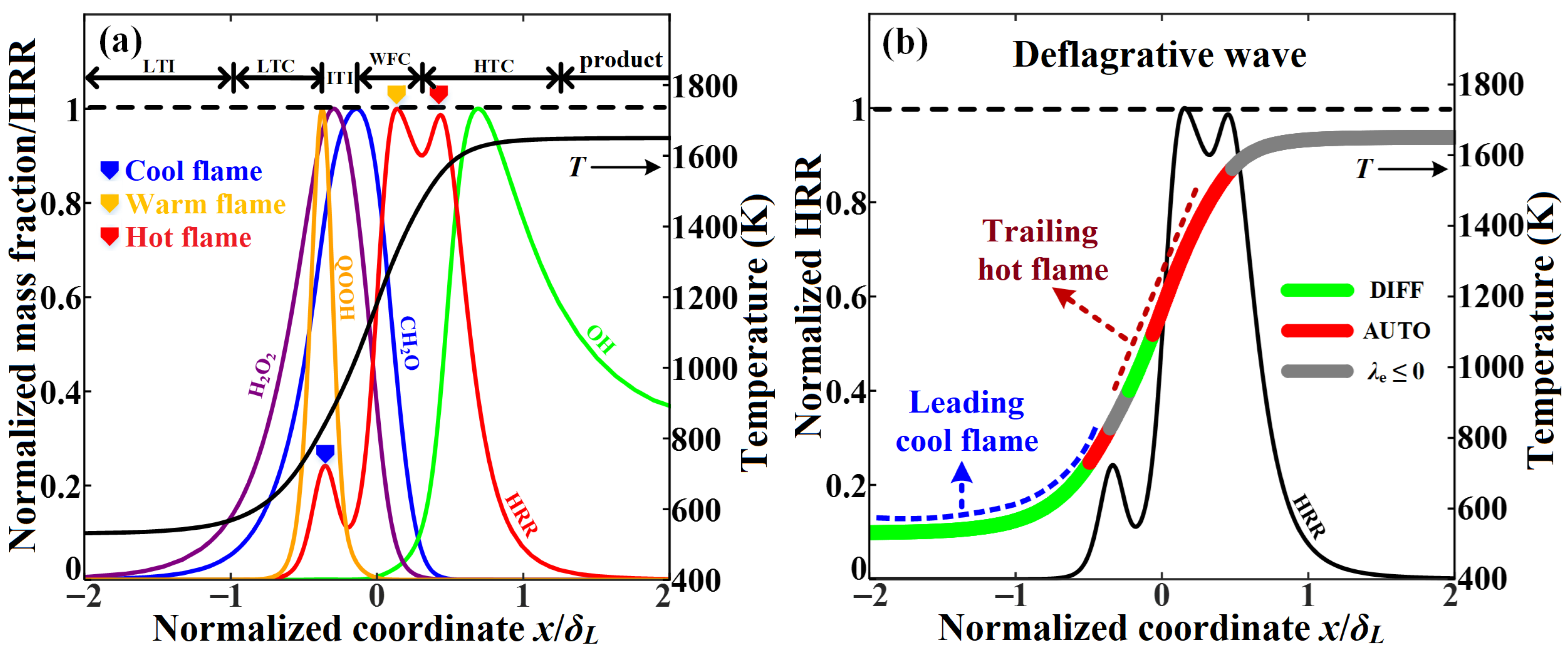
Figure 2a,b display the structure and LCMs in the laminar premixed flame with its parameters nominally identical to the statistic means of the turbulent flame (i.e., p = 30 atm, T0 = 530 K, equivalence ratio ϕ = 0.45). The spatial coordinate is normalized by the laminar flame thermal thickness δL (δL = (TbTu)/(dT/dx)max, where Tu and Tb are the unburned- and burned-side temperatures, respectively).
Due to the low-temperature behavior of DME, its HRR curve at high pressure is featured with three peaks, based on which the combustion process is divided into five stages, including the low-temperature induction (LTI), low-temperature combustion (LTC), intermediate-temperature induction (ITI), warm-flame combustion (WFC), high-temperature combustion (HTC), and combustion-depleted stage, from the incoming inlet to the product outlet. In the LTC stage, the normalized HRR is enhanced with increasing temperature, but not exceeding 0.3. The variation of low-temperature component QOOH (CH2OCH2OOH, Q denotes the radical formed via two dehydrogenations of the DME molecule) keeps in consistence with HRR; the intermediate-temperature precursors, H2O2 and CH2O, gradually accumulate. When crossing over the first HRR peak (i.e., the cool-flame front), it enters the ITI stage. In this stage, HRR turns to decrease with increasing temperature as a result of the negative temperature coefficient (NTC) effect. At the end of the HRR decreasing process, it enters the WFC and HTC stages, where HRR increases rapidly with a dominance of thermal runaway. At the same time, H2O2 and CH2O were gradually consumed, followed by the generation of hydroxyl OH. Two adjacent local peaks of HRR appear in this stage, noted as the warm-flame front and hot-flame front in sequence. The WFC front is governed by the “R + HO2 → RO + OH” and “CH2O → HCO → HO2 → H2O2 → 2 OH” reaction branches, which agrees well with the review about warm-flame combustion kinetics in Ju’s article [34]. It is noteworthy that with a continuous decrement in ϕ, the warm-flame front will be intensified and the hot-flame front will be inhibited, while the warm-flame front will disappear quickly if ϕ is increased, demonstrating that the triple peaks of HRR in the LTC/WFC/HTC structure are a unique characteristic of DME/air flame under the high-pressure lean-premixed condition. More discussion about the chemical kinetics analysis of the HRR peaks is available in the supplements.
The previous studies [35] have shown that the low-temperature reactivity of DME will be activated if the initial temperature exceeds the threshold of 530 K, and the auto-ignition tendency will become obvious until exceeding 600 K. Therefore, it is inferred that the premixed DME flame in this study is dominated by the deflagrative propagation mode with the dominance of diffusion-assisted ignition. As a verification, the LCM distribution in Figure 2b reveals that for either the leading cool flame or the trailing hot flame front, it was composed of “DIFF+AUTO” structure, where the heat/radical diffusions back from the downstream post-ignition zone played the leading role in ignition of the upstream preheating zone, thus supporting the notion of deflagration propagation mode. Nevertheless, the DIFF branch of the cool-flame front was longer, while the AUTO branch was longer for the hot-flame front, suggesting that the leading cool flame was more susceptible to diffusive transports, whereas the hot flame was controlled mainly by the auto-ignition reactions. Besides, we did not observe the existence of EXTC mode in the freely propagating laminar premixed flame structure.

3.2. Flame Surface Topology and Development in the Broken Reaction Zone Regime

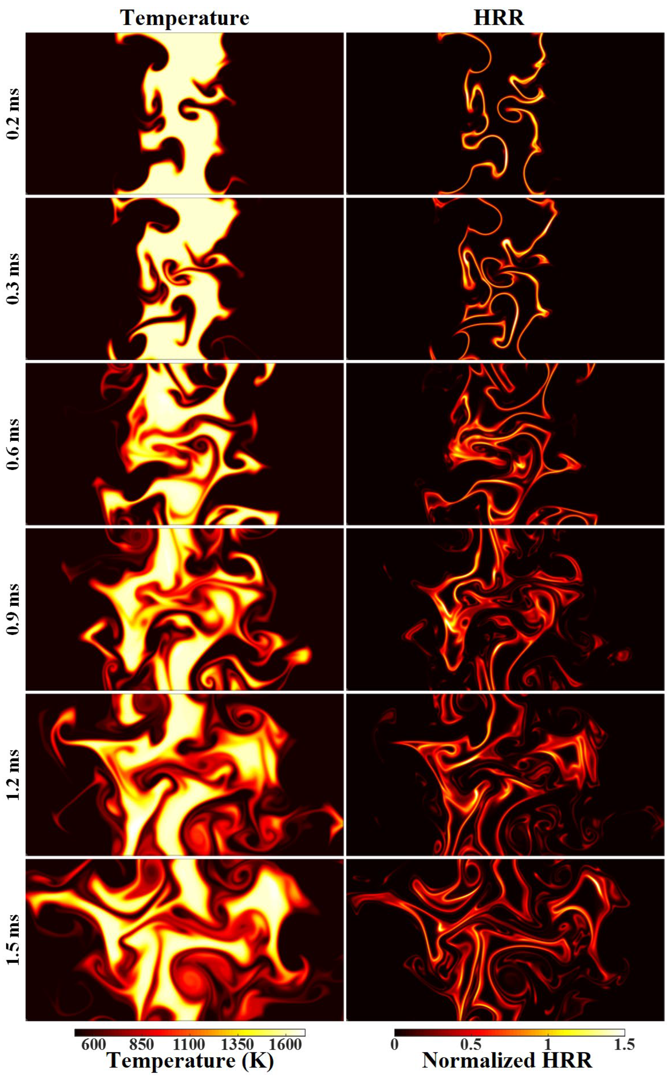
An important feature of the broken reaction zone regime with extreme turbulence is the defection of the flamelet assumption, where the continuous flame surfaces are torn up (as verified by STF statistics in Figure 1c), and thus the statistical means of scalar variables deviate significantly from the laminar flamelet state. Figure 3 depicts the evolutionary history of flame temperature and HRR, which involves three combustion stages:
(1)
Continuous flamelet mode stage (0~0.6 ms): the flame surface kept still connected and retained the basic behaviors of laminar premixed flamelet, although partial segments of the flame surfaces had shown a tendency to be thickened. By 0.3 ms, flame wrinkling/folding generated a few isolated hot pockets that propagated independently in the domain.
(2)
Combustion mode transition stage (0.6~0.9 ms): the flame changed from the laminar flamelet structure to the segmented reaction zone regime, and the phenomena of flame folding and surface thickening with generations of isolated propagating pockets became more ubiquitous.
(3)
Broken reaction zone mode stage (after 0.9 ms): the flame completely entered the broken reaction zone regime, with distributed flame segments, a remarkably thickened reaction zone, and obvious separation of the cool- and hot-flame fronts, especially at the instances of 1.2 and 1.5 ms.

3.3. Local Combustion Modes and Conditional Statistics in the Broken Reaction Zone Regime

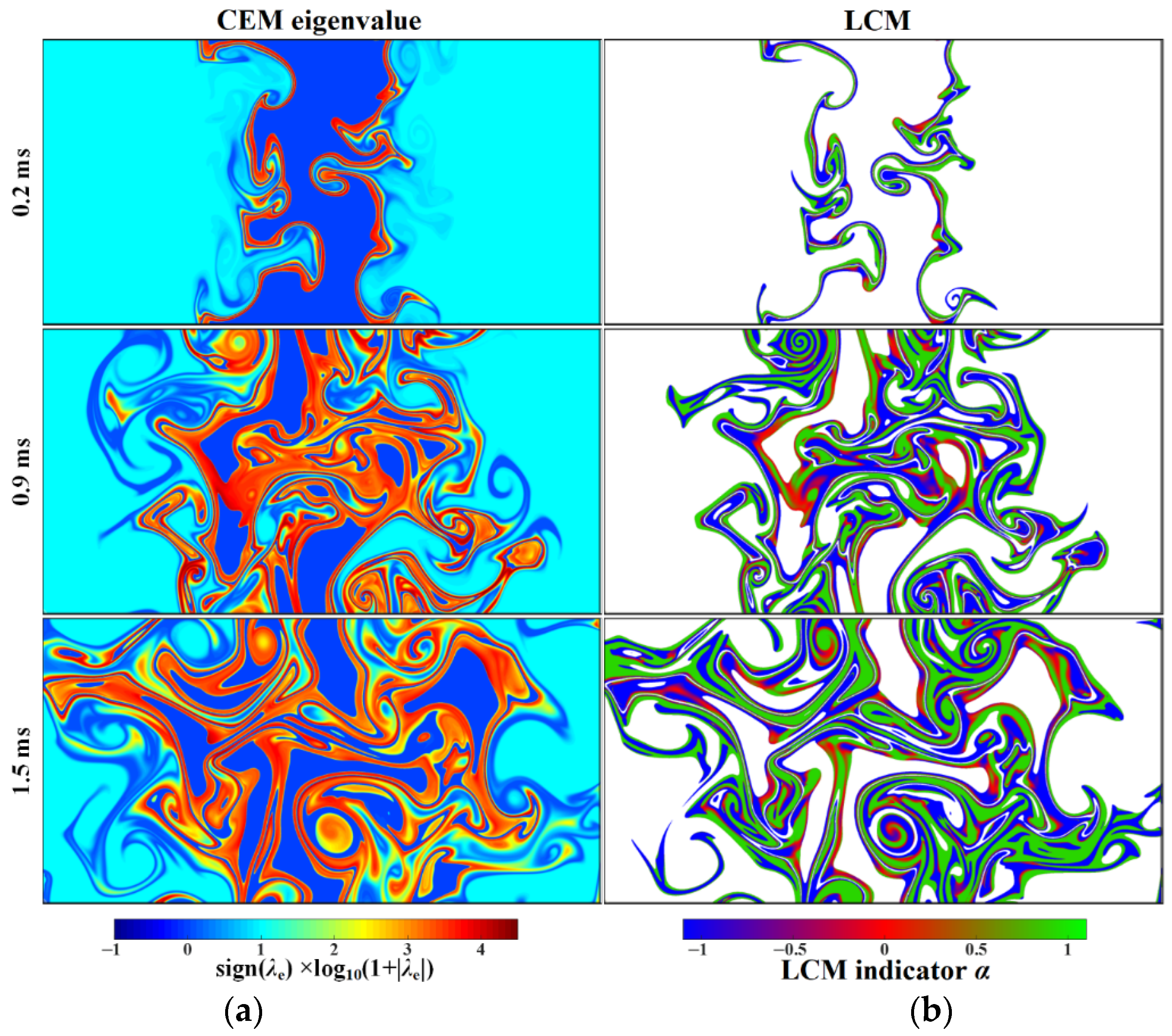
In the following, LCMs and conditional statistics will be performed to reveal the combustion mechanism in the broken reaction zone mode that commenced at t = 0.9 ms. For the post-processing, 51 datasets in the span of 1.0~1.5 ms with an equal interval of 10 μs are used for the statistical diagnostics. To examine the inner flame structure, the statistics were applied to the reaction front zone only, and the unburned fresh zone with T < 550 K and the product zone with T > 1630 K, λe < 0.1 were exclusive and thus filtered out. Figure 4 illustrates the profiles of CEM eigenvalue (sign(λe) × log10(1 + |λe|)) at t = 0.2, 0.9, and 1.5 ms, respectively, as well as the LCM distributions inside the reactive front. Blue, red, and green pixels in Figure 4b denote the EXTC, AUTO, and DIFF modes. It is noted that the DIFF and EXTC modes represent the dominance of heat/mass diffusions, but with opposite contributions to the local ignition reactions, while the AUTO mode indicates the dominant role of chemical reactions over diffusions. Therefore, the roles of diffusion and chemistry in combustion can be quantified by the LCMs. As Figure 2b shows, three local propagation modes coexisted in the turbulence field, including the deflagration wave, spontaneous ignition wave, and mixing wave.
Unlike the laminar flamelet LCM structures as shown in Figure 2b, the EXTC mode existed extensively in the turbulent flame sheet [23] (Figure 4b), which suggests that the dissipative diffusion processes that play an inhibiting role in fuel ignition are a distinctive feature in the extreme turbulence condition. Additionally, with the overall conservation property in the reacting flow, the dissipated diffusion losses may likely facilitate ignition in the vicinity area, which may explain the presence of DIFF mode by EXTC. Hence, the chemical state depends strongly on the progress variable as well as on the local dissipation condition. Besides, it is seen that when developed into the segmented reaction zone regime, more complex structures were generated, say thickened reaction sheets with “DIFF+EXTC” LCMs in the morphology of a spiraling vortex, implicating that the statistical mean state may deviate remarkably off the laminar premixed flamelet. In the following, the normalized temperature is defined as the flame progress variable, and the turbulent statistical data, including HRR, fuel consumption rate, and diffusive sources, are normalized by their maxima in the laminar flamelet counterpart to depict the deviation degree.
Figure 5 shows the probability density functions (PDFs) with a statistical means of HRR and fuel consumption rate conditioned in temperature space, as well as the shares of HRR and fuel consumption rate at different combustion ranges. It indicates that for the cool-flame front (about 800 K), the mean HRR and fuel consumption rate were almost the same as those of the laminar flamelet; however, for the hot-flame front, its absolute averages were considerably lower than the latter counterpart. Hence, it is concluded that the hot-flame front was much more sensitive to extreme turbulence compared with the cool-flame front. This goes exactly against the existing theory [1,36], which suggests that turbulence would probably affect the leading preheating zone rather than the trailing high-temperature reaction sheet layer. As verified in Figure 5c, the shares of HRR and fuel consumption rate in the turbulent case shifted to the low-temperature region by 0.16 and 0.19, respectively, in comparison with the laminar counterpart, demonstrating that the cool-flame intensity was amplified under the extreme turbulence condition. Considering that PDF actually corresponds to grid number and thus the volume fraction, the high PDF of the low-temperature zone also indicates the enlargement of the cool-flame front, which indeed surpasses the hot-flame front in the segmented reaction zone regime with strong turbulence. In contrast, in the laminar flamelet (Figure 2b), the thickness of the cool-flame zone is about half that of the hot-flame zone. Additionally, the average statistics of HRR indicate that the turbulent flame in the broken reaction zone regime basically retained the three-staged behavior of that in the laminar flamelet, and the warm-flame front in the turbulent case had a lower HRR peak versus the hot-flame front. However, the contribution of the warm-flame front (corresponding to the temperature range 975~1450 K) to the overall heat production was increased slightly by 0.04, remarkably surpassing that of the hot-flame front (T > 1450 K). As a result, the extreme turbulence extended not only the low-temperature preheating zone, but also the warm-flame front with intermediate temperatures.
The change in heat/mass diffusions in the segmented reaction zone regime was also significant. As displayed in Figure 6, for either heat or DME/O2 diffusions, the high probability was centered at zero, with basically equal disparities in the positive and negative source regions. The statistically averaged intensity was lower than that of the laminar flamelet, especially in the range T = 700–1300 K, which corresponds to the reaction layer with the most intense mixing rates. The phenomenon of reduction in statistical means of diffusion is essentially due to the fact that scalar gradients and thus their diffusion sources were mitigated in the intense turbulence mixing condition. In overall, the PDF of the heat conduction source decreased with temperature, while the fuel and oxidant diffusion sources increased instead, suggesting that heat and fuel/oxidizer diffusive transports in the extreme turbulent premixed flame brush were still unidirectional, but in opposite directions. The high probabilities of intense positive/negative diffusive transports imply the presence of DIFF and EXTC modes in the strong turbulence condition. To verify this inference, the proportion of each LCM mode was estimated by statistics conditioned on the positive/negative diffusive fluxes. As shown in Figure 6, in the region with positive heat conduction flux and negative diffusion fluxes of DME/O2, which corresponds to the low-temperature preheating zone that gains sources from the trailing hot-flame brash, the DIFF mode with a probability of more than 70% was dominant. Conversely, in the region with opposite transport fluxes that was situated in the hot-flame zone, the EXTC mode became dominant, with its probability accounting for over 60%. The AUTO mode was comparatively negligible in either region.
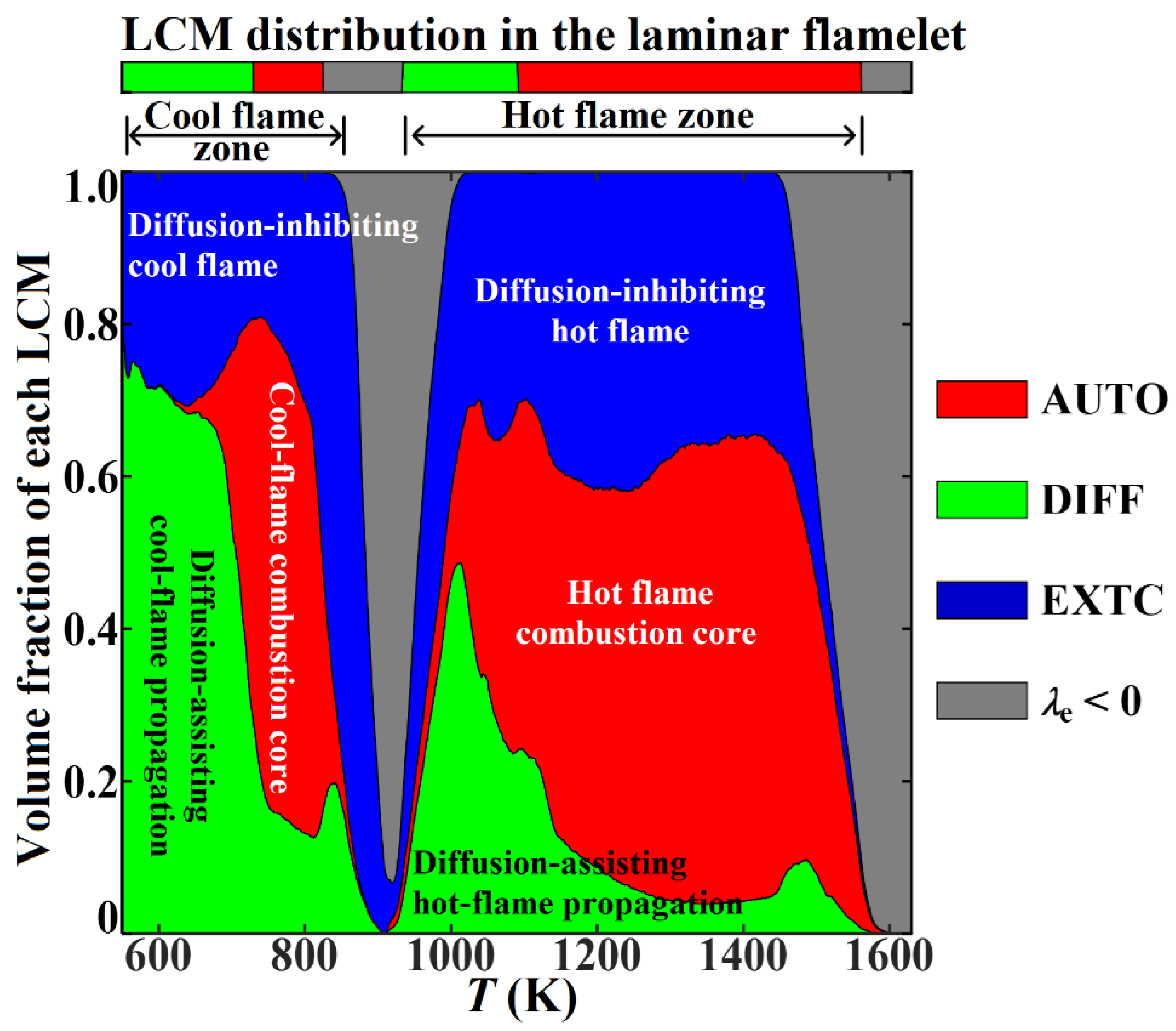
The significant variations in diffusion structure will inevitably affect the LCM distribution. Figure 7 shows the statistics of LCM modes conditioned in temperature space, which indicates the validity of cool- and hot-flame fronts in the strongly turbulent premixed brash. In the cool-flame region, the low-temperature combustion core (AUTO) had been expanded, but still remained around 800 K; the DIFF mode was dominant, indicating the leading role of diffusivity in assisting the cool-flame propagation as well as the formation of its combustion core. In the hot-flame region, the EXTC mode was dominant, indicating the inhibiting role of diffusive transports in the high-temperature combustion. Moreover, the local quenching phenomenon in the EXTC mode was also significant in the cool-flame front. It is analyzed that the initial mixtures of 530 K or so do not have sufficient radicals and heat pockets to generate notable diffusion sources, and thus support the EXTC mode. Such a high portion of EXTC mode in the low-temperature region is attributed to the local quenching events, essentially due to the rapid loss of heat when the post-ignition mixture was thereafter subjected to intense dissipative processes. We also observed similar LCM behavior in the hot-flame front, even though the AUTO area was expanded and the DIFF mode was less important than EXTC. Therefore, in the segmented reaction zone regime, the dominance of heat/mass diffusions had occupied the entire temperature domain, compared with the limited influence domain in the laminar flamelet.
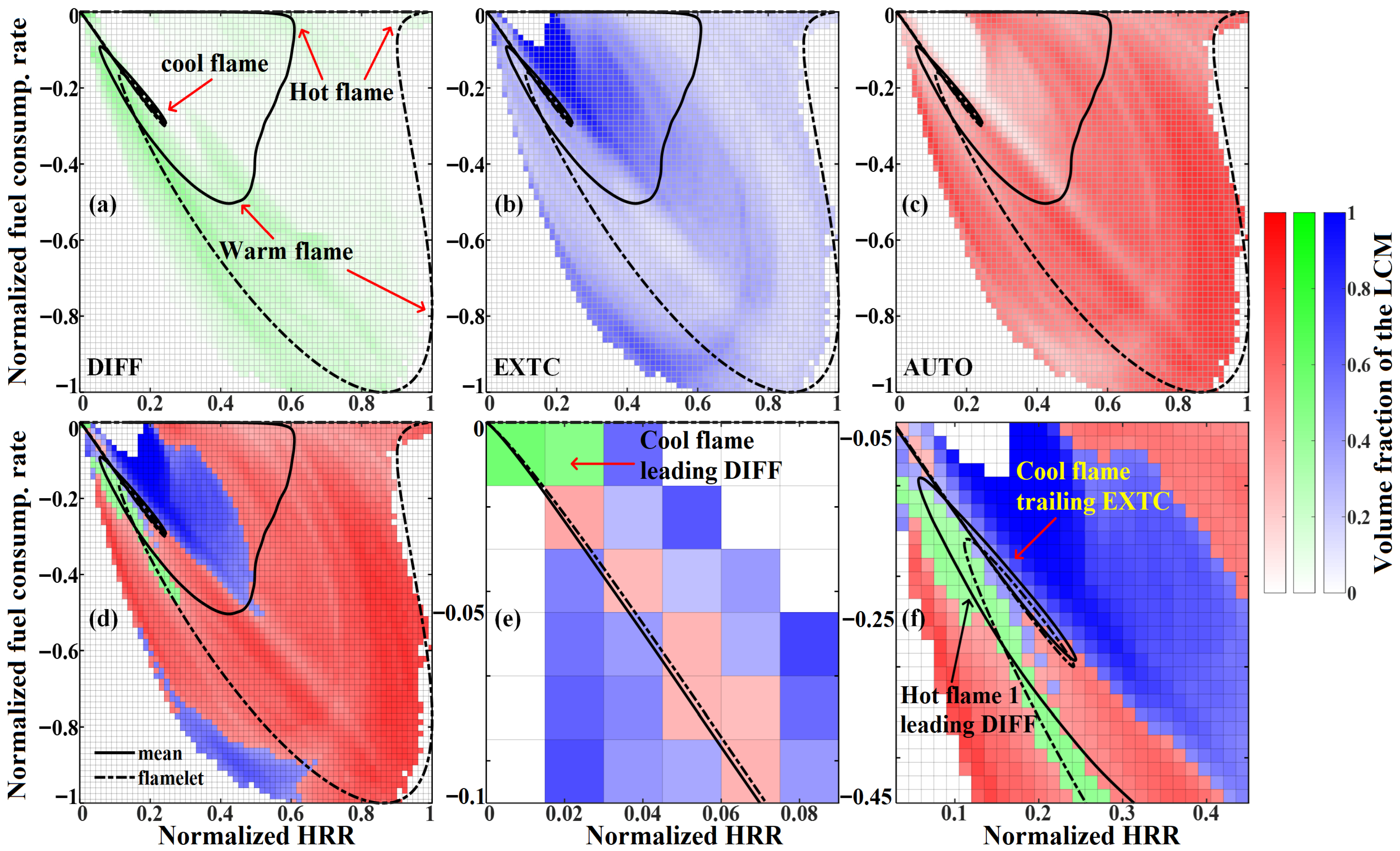
The JPDF, as displayed in Figure 8, can reveal the probability preference of each LCM mode in the HRR/fuel consumption rate joint space. It is seen that the DIFF mode was mainly concentrated within the region between the cool-flame front and warm-flame front, which is consistent with the typical structure of a laminar deflagration wave (Figure 2b). In addition, the DIFF points in Figure 8a were basically clustered around a fitting line with the slope −1, suggesting that the local heat/mass diffusions can enhance HRR and fuel consumption rate at the same time. The EXTC points prevailed in two zones, including one that is located within the statistical mean closed curve, and the other that is outside the closed curve corresponding to the laminar flamelet. This suggests that combustion inhabitation due to the local diffusive losses existed in two zones: in zone I at the vicinity of the cool-flame reactive front, both HRR and fuel consumption were suppressed; in zone II of the hot-flame front, HRR was suppressed only. The AUTO mode was mainly distributed outside the statistical mean curve of the turbulent flame, suggesting that the enhancements of the local HRR and fuel consumption were governed by chemical reactions.
In summary, the conditional statistics and LCM analysis suggest that in the segmented reaction zone regime, the turbulent reaction front and heat/mass diffusion structure were significantly changed. Specifically, the reaction zone was thickened, especially for the cool-flame front, which played as the most important contributor to HRR, fuel consumption, and reaction enhancement. Furthermore, the interplay of heat/mass diffusions resulted in the prevalence of DIFF and, especially, EXTC modes within the flame brash.

3.4. Dynamical Processes and Diffusive Transport Mechanism in the Broken Reaction Zone Regime

The typical local phenomena, such as cool flame enhancement and hot flame thickening, are still unclear, so in this section, the localized features and heat/mass diffusion physics are examined with deeper insights.

3.4.1. Cool Flame Reaction Enhancement in the Turbulence

As Figure 5c shows, in the broken reaction zone regime, HRR of the cool-flame front was intensified, which in the following part will be explained by investigating the flame dynamical evolution process. In Figure 9, HRR is normalized by its maxima in the laminar flamelet, and at the same time, the flame structure is indicated by three temperature iso-contours, i.e., 725 K that corresponds to the demarcation point between the DIFF and AUTO branches in the leading cool flame front (Figure 2b), 975 K that corresponds to the minimal-HRR point, and 1100 K that corresponds to the demarcation point between the DIFF and AUTO branches in the trailing hot flame. As illustrated in Figure 9, the cool-flame enhancement by vortex evolution is formed via two stages: (I) with the strong turbulence interaction, unburned flammable mixtures penetrating the torn-up flame surfaces are sucked into the interior reaction zone (for instance, the penetrating path 2), resulting in the “spiral corridor” flow structure that is filled by unburned mixtures surrounded by corrugated cool flame fronts. (II) Then cool flames in the spiral structure propagate in acceleration towards the unburned side with the aid of heat/mass diffusions, leading to the cool-flame enhancement phenomenon with its normalized HRR far exceeding the reference level (above 0.5). Figure 10a lists the dominating reaction exothermicities at t = 1.35 ms compared with the laminar flamelet, which indicates that the relative importances of the major endothermic/exothermic reactions were basically identical to that in the laminar flamelet. Therefore, it is assumed that the cool-flame enhancement arose from the intensification of all relevant chemical pathways by the strong vortex interaction in turbulence, rather than by a few specific reactions. Meanwhile, Figure 10b–d show that the low-temperature chemical reactions were enhanced by at least 2.5 times versus the laminar flamelet counterpart, which is consistent with the statistics in the previous section.
Figure 9. The normalized HRR evolution process of a local cool-flame reaction front in the turbulence domain. The cyan, green, and yellow solid lines depict the iso-surfaces T = 725, 975, and 1100 K, respectively. The dot-dashed line represents the Lagrangian trajectories of massless fluid parcels that are initially sampled at t = 1.2 ms along the lines L1 and L2.
Energies 18 04357 g009
Figure 10. (a) Comparisons of the key reactions’ HRRs between the turbulent and laminar flamelet at t = 1.35 ms in the temperature range T < 975 K (HRRs are normalized by the corresponding maxima of R151, and only the reactions with their normalized HRR above 0.1 are presented). (bd) HRRs of R9, R151, and R160 that are normalized by the corresponding maxima in the laminar flamelet as a function of temperature. The chemical equations corresponding to the reaction indexes are shown in Table 1.
Energies 18 04357 g010
Table 1. Chemical equations corresponding to the reaction indexes in Figure 10.
Reaction IndexChemical EquationNote
R9H + O2 (+M) = HO2 (+M)
R14HO2 + HO2 = H2O2 + O2Duplicate reaction
R15HO2 + HO2 = H2O2 + O2Duplicate reaction
R27HCO + O2 = CO + HO2
R40CH2O + OH = HCO + H2O
R132CH3OCH3 + OH = CH3OCH2 + H2O
R151CH3OCH2 + O2 = CH3OCH2O2
R156CH3OCH2O2 = CH2OCH2O2H
R157CH2OCH2O2H = OH + CH2O + CH2O
R158CH2OCH2O2H + O2 = O2CH2OCH2O2H
R159O2CH2OCH2O2H = HO2CH2OCHO + OH
R160HO2CH2OCHO = OCH2OCHO + OH
R162HOCH2OCO = HOCH2O + CO
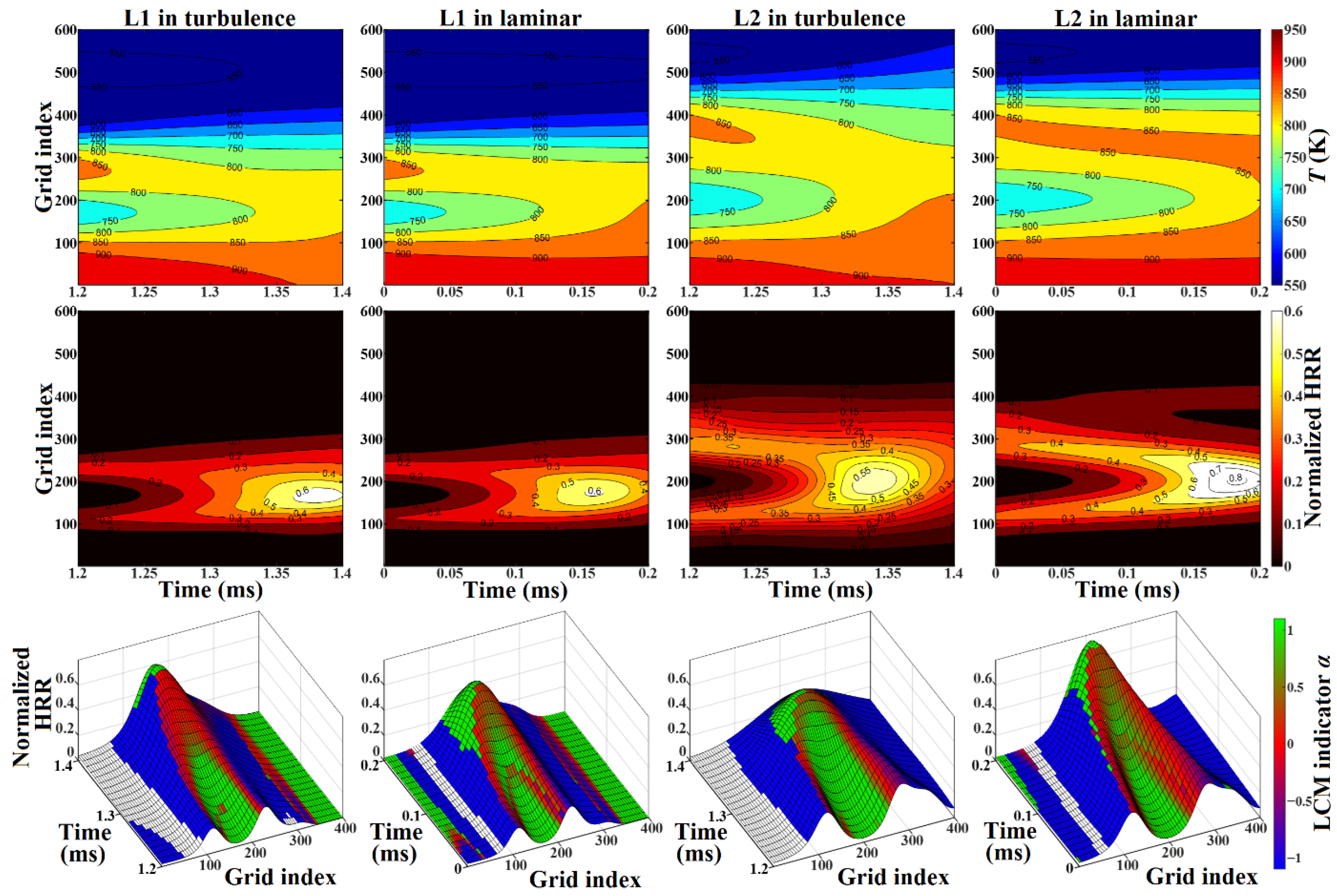
The cool flame propagation in turbulence is dramatically different from the laminar premixed propagation. In the following part, the Lagrangian tracking technique with analyses by LCM and diffusion index (DI) will be conducted to further reveal the role of heat/mass diffusions in turbulent cool-flame propagation. In order to investigate the cool-flame propagation in the spiral corridor, 600 × 2 massless fluid particles (white dotted lines L1 and L2 at t = 1.20 ms as shown in Figure 9) are sampled for the Lagrangian tracking computations, with its detailed algorithm available in [37]. The reason for performing Lagrangian tracking is that the time scale of turbulence in the broken reaction zone regime is comparatively small versus the characteristic flamelet time scale, so if examining the flame evolution dynamics in the Eulerian coordinate system, it may probably induce remarkable errors due to the intense turbulence transports. Besides, the solution data on lines L1 and L2 were also fed as initiation inputs to launch the transient simulations in the laminar unstretched planar premixed flame configuration, and its comparison with the turbulent results can indicate the effectiveness of turbulence on flame propagation. The detailed descriptions about the laminar flame models and methods can be referred to in our previous publication [38].
Figure 11 shows time evolutions of temperature, HRR, and LCMs for the samples L1 and L2 in turbulent and laminar conditions, respectively, which depicts that temperature and HRR evolution behaviors were basically the same in the turbulent and laminar conditions. After approximately 0.1 ms, HRR between the two cool-flame fronts was enhanced (the normalized intensity exceeding 0.3), which is due to the formation of a spiral corridor structure where mixtures with different progress variables interplay with each other, as well as the subsequent energization of cool flames by diffusive transports. This observation can be also verified by the LCM analysis, as displayed in the third row of Figure 11. Taking line L1 in turbulence as an example, at the initial moment t = 1.2 ms it shows two cool flames propagating in the opposite directions, with each flame front denoted by an EXTC-AUTO-DIFF profile pattern. Between the dual fronts was the DIFF mode, where heat/mass diffusions assisted the fuel ignition; as these two flame fronts got closer, HRR in the DIFF mode increased significantly, and the DIFF mode gradually disappeared and evolved to AUTO, indicating that the cool flame combustion developed into the chemistry-dominating phase. As a result, the mapping accordance between laminar flamelet and turbulent combustion in the broken reaction zone regime, and thus the flamelet consumption, would become defective in the intense turbulence condition. At last, with further increment in the low-temperature HRR, the AUTO mode changed to DIFF mode again, and the transition to the intermediate-temperature combustion phase commenced.
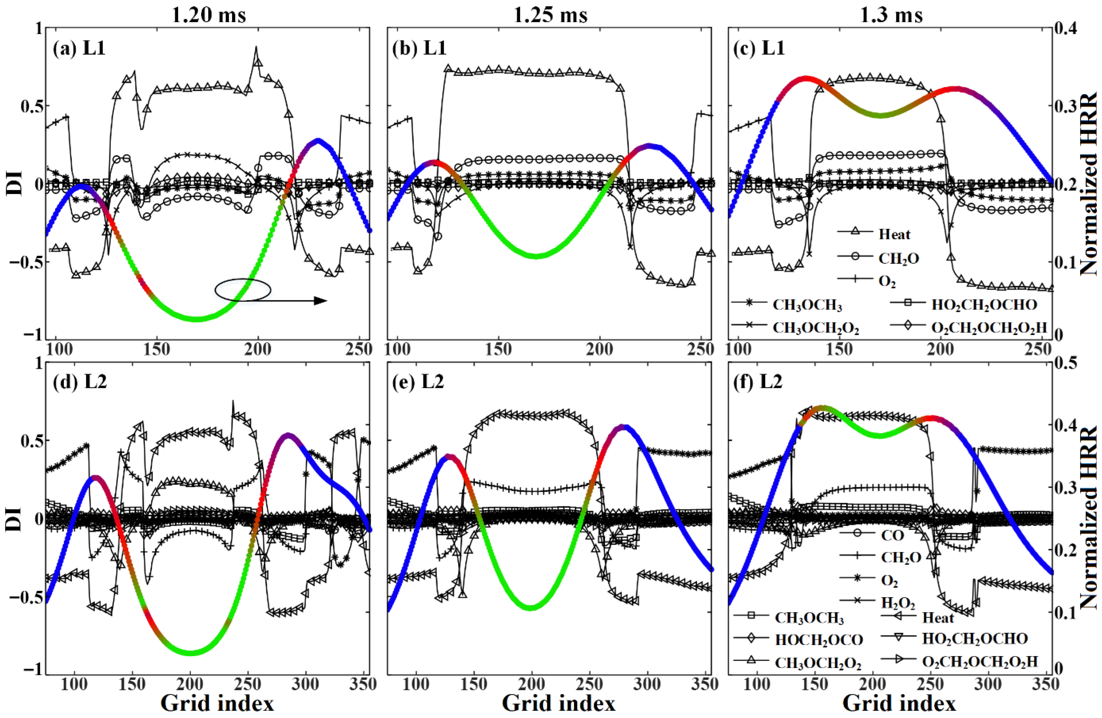
In this part, DI will be employed to clarify the dominating diffusive subprocesses in the cool flame enhancement. As indicated in Formula (2), ϕs =be·s stands for the projected contribution of diffusion sources to CEM along its eigenvector direction. Hence, we propose the DI index, as defined in Formula (3), to describe the contribution and thus relative importance of each diffusion subprocess to LCM. n = 1~K designates mass diffusion with K the total number of diffusive species, and n = K+1 designates the heat conduction. Furthermore, in combination with the sign of the LCM indicator α, DIn can also reveal the impact of nth diffusive process on ignition.
D I n = b e n s n n = 1 K + 1 b e n s n
As shown in Figure 12, heat conduction played as the most important diffusivity throughout the cool flame enhancement process (t = 1.20–1.30 ms), with the peaking DIheat > 0.5 in the DIFF zone and DIheat < −0.4 in the EXTC zone. CH2O diffusion with |DICH2O|≈0.2 was of secondary importance, and it changed from a negative effectiveness (DICH2O < 0) at t = 1.20 ms to positive (DICH2O > 0) at t = 1.25 and 1.30 ms. CH3OCH2O2 diffusion also assisted the local ignition (DICH3OCH2O2≈0.15) in the early stage t = 1.2 ms, but its assisting effect was depressed with enhancing HRR. The significance of fuel CH3OCH3 appeared only in the later stage when fuel was basically consumed. For the remaining species, say HOCH2OCO, HO2CH2OCHO, and O2CH2OCH2O2H, etc., the role of its diffusion on the low-temperature reactivity was ignorable. Additionally, it is noteworthy that in the EXTC zone at the periphery of the dual cool-flame fronts, DIheat and DIO2 have a comparable absolute value but opposite signs, indicating their inhibiting and enhancing impacts on the local ignition.
In summary, in the fragmented reaction zone regime, turbulence folding/stretching creates the spiral flow structure that is filled with mixtures of varying progress variables, and the low-temperature reactivity of which is thereafter intensified by heat/radical diffusions, which is responsible for the cool-flame enhancement phenomenon. The formation mechanism of isolated, self-sustaining cool flame propagation in the intense turbulence as well as its evolution dynamics is further discussed in the Supplement Materials.

3.4.2. Hot Flame Zone Thickening in Turbulence

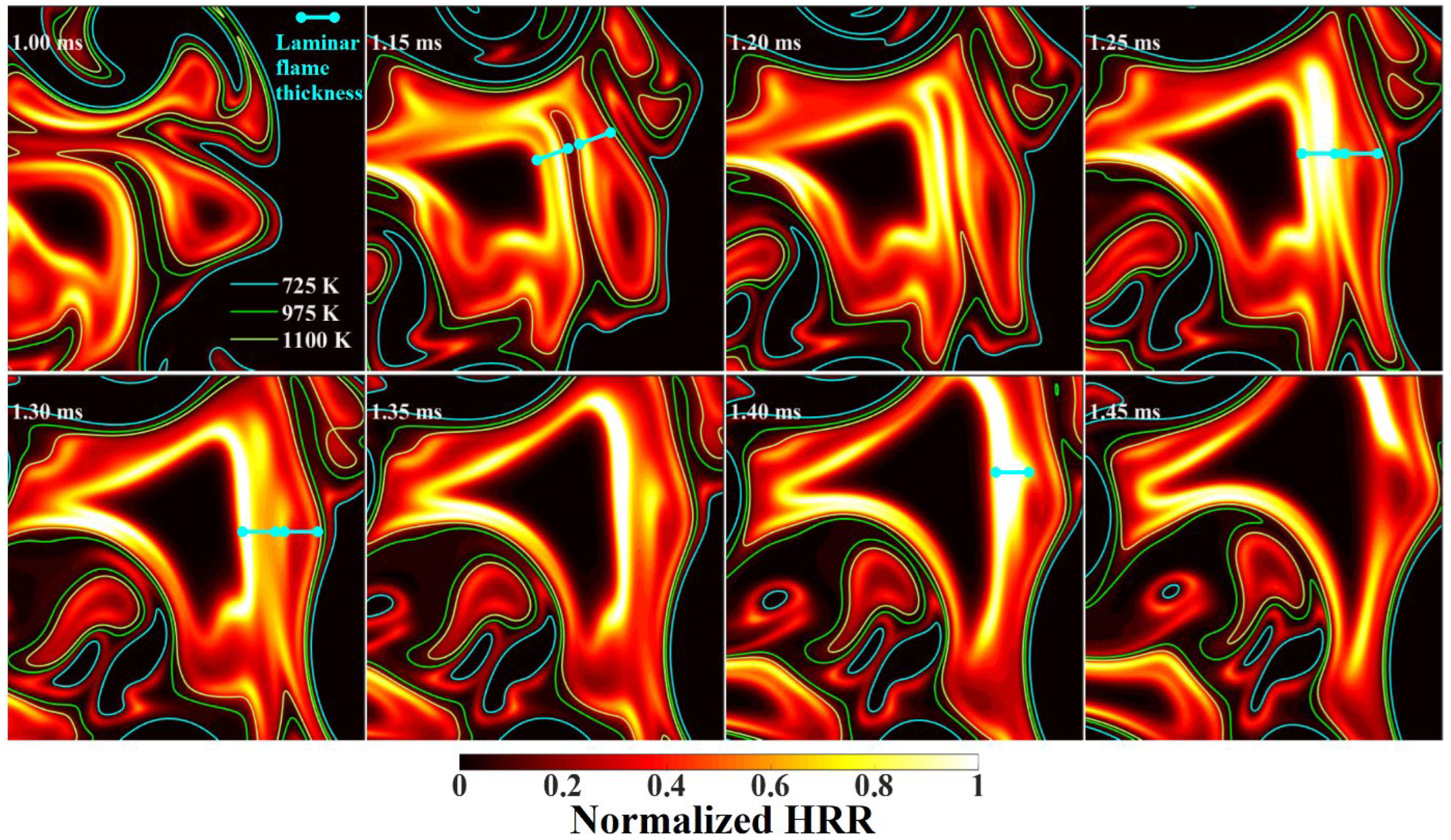
Apart from the cool-flame thickening, we also observed frequent surface merging/thickening phenomenon in the hot flame zone. It is shown in Figure 13 that, being similar to the cool-flame evolution dynamics, high-temperature fluids with varying progress variables were generated by turbulence mixing, which propagated in opposite directions. In this reactive structure, the lower progress variable mixtures will catch fire quickly and then merge with the nearby hot flames, resulting in hot flame thickening. If the contour T = 1100 K (yellow line in Figure 13) is chosen as a simple definition criterion of the hot flame zone, the dynamical process described above creates a hot-flame front that is about twice the laminar flamelet thickness (t = 1.25 ms in Figure 13). Hot-flame front thickening is one of the most remarkable features in the broken reaction zone regime against the thin reaction zone regime, i.e., extreme eddies intrude into the core reaction zone and destroy the continuous flame surface, thus changing the fundamental structures of the flame reaction zone. In the following, HRR in the hot branches will be emphasized.
Figure 14 shows the normalized HRR evolution in the hot flame thickening process, which shows that overall, the HRR level of the turbulent flame brush was lower than that of the laminar flamelet before the hot flame merging (t < 1.2 ms). However, after complete coalescence of hot-flame fronts, the secondary HRR peak commenced to increase significantly and eventually reached approximately 2. It is noted that this phenomenon differs from the HRR enhancement solely by the turbulent stretching effect [39]. The former arises from the formation of spiral flow structures in extreme turbulence with positive flame propagation and thus may occur in the broken reaction zone regime only, while the latter is due to a wrinkled continuous flame front subjected to the stretch rate. Besides, in the hot-flame zone of the laminar flamelet, as shown in Figure 2b, the DIFF mode was dominant below 1100 K, while the hot-flame thickening process occurred above 1100 K, which belongs to the AUTO mode by the flamelet results. The role of heat/radical diffusions in hot-flame thickening/enhancement will be examined as follows.
Figure 15 demonstrates LCM evolution during the hot flame thickening process, which shows that for the two freely propagating fronts A and B, the LCMs at the beginning (t = 1.1 ms) were AUTO, whereas mixtures between them with less progress variables were in the DIFF mode. With the collision of these two propagating fronts (t = 1.2 ms), temperatures in the DIFF zone kept increasing and exceeded 1100 K, and the DIFF mode still occupied a considerable area. This suggests that diffusions still dominate the ignition, even though the local mixture temperature exceeds 1100 K, which is the threshold of AUTO mode for the laminar flamelet. When the two hot fronts were completely merged (t > 1.3 ms), the AUTO mode became dominant, and HRR was remarkably enhanced. Therefore, it is concluded that the heat/radical diffusions were significant in the early phase of hot flame thickening only. To clarify the key diffusive scalars with their impact on flame brush thickening, the cutline L4 at t = 1.2 ms is sampled for the next DI detection.
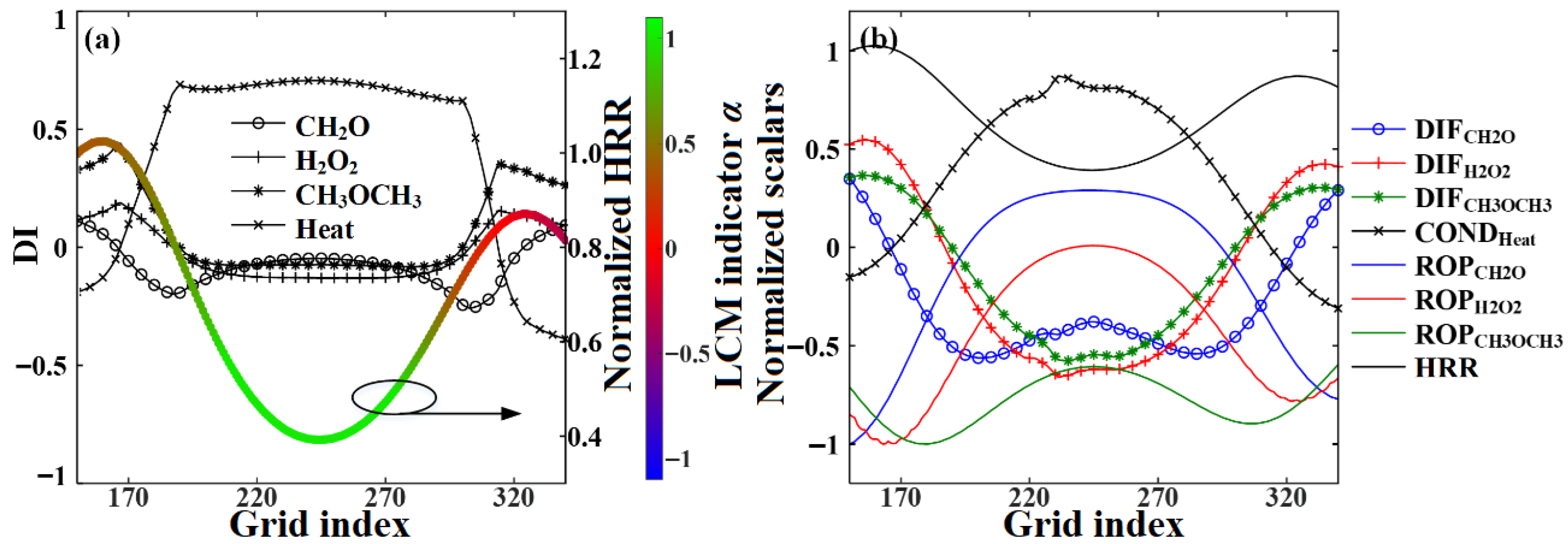
Figure 16 illustrates DI distributions of the most important diffusive processes along the cutline L4 at t = 1.2 ms, as well as the corresponding transport budget analysis results. It is seen that the most important diffusive sub-process in the core region of DIFF mode (color in green, grid indexed within 220–270) was heat conduction (DI > 0.6), and the heat conduction flux with a positive contribution was significantly stronger than HRR. Therefore, heat conduction played a crucial role in the hot-flame HRR enhancement. In contrast to the cool-flame enhancement process, the diffusive process with secondary importance in the DIFF zone was CH2O, which has negative DI and diffusive flux values. Since CH2O is an important precursor in the high-temperature chemistry, a negative diffusive source tends to inhibit the hot-flame reactivity and thus leads to the negative DI. In the hot-flame branches A and B (grid indexed below 170 or above 320), CH2O with positive diffusion flux and DI values turned to favor reactivity. However, since it was already transitioned into the AUTO mode, the importance of CH2O became unimportant. Similar changes in DI are also observed for species H2O2 and CH3OCH3. As depicted in Figure 16, the net rate of production (ROP) for H2O2 was close to zero in the DIFF core zone and remained negative in A/B flame zone, indicating that the diffusive transport of H2O2 from the DIFF core zone to A/B fronts was responsible for the depletion of H2O2 stocks that were created during the early-stage low-temperature reactions in the DIFF core. This would be the underlying reason for the subsequent hot-flame HRR enhancement during t = 1.3–1.4 ms, as shown in Figure 14.
In summary, the hot flame thickening phenomenon in the broken reaction zone regime is the result of strong turbulence transport interplaying with the heat/mass diffusions. The strong turbulent transport creates spiral eddies consisting of intermixed mixtures with varying progress variables. Then, the hot-flame fronts merge together quickly under the effects of flame folding and diffusive transports, forming the significantly thickened hot reacting fronts with the HRR enhancement of low-progress-variable mixtures.

4. Conclusions

In this paper, the propagation and heat/radical diffusion physics of a high-pressure DME/air turbulent lean-premixed flame with Ka = 200 are investigated numerically by DNS with detections by means of LCM/DI analyses and conditional statistics. The main conclusions are as follows:
(1)
The three-staged combustion, including cool-flame, warm-flame, and hot-flame fronts, is a unique behavior of DME flame under the elevated-pressure, lean-premixed condition. Compared with the laminar flamelet, in the broken reaction zone regime the reacting front structure as well as its inner diffusion processes has changed significantly. The reaction zone thickness increases remarkably, and the HRR and fuel consumption rate in the cool-flame zone are increased by 16% and 19%, respectively. The diffusion effect not only enhances flame propagation, but also suppresses local HRR and fuel consumption.
(2)
The strong turbulence interplaying with diffusive transports is the underlying physics for the enhancements in cool- and hot-flame fronts. In the turbulence field with strong flame folding and eddy mixing, it created intermixed reacting fronts with varying progress variables; the heat/radical diffusions, on the other hand, are the intrinsic mechanisms for the formation of flame intensification and thickening phenomenon.
(3)
For the cool-flame front, diffusive transports of heat, CH2O, CH3OCH2O2, and CH3OCH3 are of the governing significances for the flame thickening and combustion enhancement. For the hot-flame front, heat conductivity is most dominant, and the diffusions of CH2O, H2O2, and CH3OCH3 are of less importance with an inhabitation impact.
(4)
The extreme turbulence transport would induce the separation of cool and hot flame fronts, and evolve to independent freely propagating cool-flame fronts. The strong low-temperature chemistry of DME is responsible for the formation of self-sustaining cool flames, which is supported by diffusions of low-temperature species and heat.

Supplementary Materials

The following supporting information can be downloaded at: https://www.mdpi.com/article/10.3390/en18164357/s1.

Author Contributions

Conceptualization, Y.Z. and Y.K.; methodology, Y.K.; software, Y.K.; validation, P.Z.; formal analysis, Y.Z.; investigation, Y.Z. and Y.K.; resources, Y.K.; data curation, Y.Z. and X.T.; writing—original draft preparation, Y.Z.; writing—review and editing, Y.Z.; visualization, Y.Z.; supervision, X.H.; project administration, X.H. and X.T.; funding acquisition, Y.K. All authors have read and agreed to the published version of the manuscript.

Funding

This research was funded by the National Natural Science Foundation of China (Grant: 22178032), the Natural Science Foundation of Chongqing (Grant: CSTB2023NSCQ-MSX1045), the National Key Research and Development Program of China (Grant: 2022YFB4004404), and the University Natural Science Research Project of Anhui Department of Education (Grant: RZ2300002984). And The APC was funded by National Natural Science Foundation of China (Grant: 22178032).

Data Availability Statement

The data can be available by contacting with the corresponding author (Y.H. Kang).

Acknowledgments

The present research was supported by the National Natural Science Foundation of China (Grant: 22178032), the Natural Science Foundation of Chongqing (Grant: CSTB2023NSCQ-MSX1045), the National Key Research and Development Program of China (Grant: 2022YFB4004404), and the University Natural Science Research Project of Anhui Department of Education (Grant: RZ2300002984).

Conflicts of Interest

The authors declare no conflict of interest.

References

  1. Steinberg, A.M.; Hamlington, P.E.; Zhao, X.Y. Structure and dynamics of highly turbulent premixed combustion. Prog. Energy Combust. Sci. 2021, 85, 100900. [Google Scholar] [CrossRef]
  2. Skiba, A.W.; Carter, C.D.; Hammack, S.D.; Driscoll, J.F. Premixed flames subjected to extreme levels of turbulence part II: Surface characteristics and scalar dissipation rates. Combust. Flame 2022, 239, 111703. [Google Scholar] [CrossRef]
  3. Skiba, A.W.; Wabel, T.M.; Carter, C.D.; Hammack, S.D.; Temme, J.E.; Driscoll, J.F. Premixed flames subjected to extreme levels of turbulence part I: Flame structure and a new measured regime diagram. Combust. Flame 2018, 189, 407–432. [Google Scholar] [CrossRef]
  4. Yuen, F.T.C.; Gülder Ö, L. Turbulent premixed flame front dynamics and implications for limits of flamelet hypothesis. Proc. Combust. Inst. 2013, 34, 1393–1400. [Google Scholar] [CrossRef]
  5. Tamadonfar, P.; Gülder Ö, L. Experimental investigation of the inner structure of premixed turbulent methane/air flames in the thin reaction zones regime. Combust. Flame 2015, 162, 115–128. [Google Scholar] [CrossRef]
  6. Seffrin, F.; Fuest, F.; Geyer, D.; Dreizler, A. Flow field studies of a new series of turbulent premixed stratified flames. Combust. Flame 2010, 157, 384–396. [Google Scholar] [CrossRef]
  7. Schneider, C.; Dreizler, A.; Janicka, J. Fluid dynamical analysis of atmospheric reacting and isothermal swirling flows. Flow Turbul. Combust. 2005, 74, 103–127. [Google Scholar] [CrossRef]
  8. Li, Z.S.; Li, B.; Sun, Z.W.; Bai, X.S.; Aldén, M. Turbulence and combustion interaction: High resolution local flame front structure visualization using simultaneous single-shot PLIF imaging of CH, OH, and CH2O in a piloted premixed jet flame. Combust. Flame 2010, 157, 1087–1096. [Google Scholar] [CrossRef]
  9. Zhou, B.; Brackmann, C.; Wang, Z.; Li, Z.; Richter, M.; Aldén, M.; Bai, X.S. Thin reaction zone and distributed reaction zone regimes in turbulent premixed methane/air flames: Scalar distributions and correlations. Combust. Flame 2017, 175, 220–236. [Google Scholar] [CrossRef]
  10. Zhou, B.; Brackmann, C.; Li, Q.; Wang, Z.; Petersson, P.; Li, Z.; Aldén, M.; Bai, X.S. Distributed reactions in highly turbulent premixed methane/air flames: Part, I. Flame structure characterization. Combust. Flame 2015, 162, 2937–2953. [Google Scholar] [CrossRef]
  11. Zhou, B.; Brackmann, C.; Li, Z.; Aldén, M.; Bai, X.S. Simultaneous multi-species and temperature visualization of premixed flames in the distributed reaction zone regime. Proc. Combust. Inst. 2015, 35, 1409–1416. [Google Scholar] [CrossRef]
  12. Wang, Z.; Zhou, B.; Yu, S.; Brackmann, C.; Li, Z.; Richter, M.; Aldén, M.; Bai, X.S. Structure and burning velocity of turbulent premixed methane/air jet flames in thin-reaction zone and distributed reaction zone regimes. Proc. Combust. Inst. 2019, 37, 2537–2544. [Google Scholar] [CrossRef]
  13. Fan, Q.; Liu, X.; Cai, X.; Brackmann, C.; Alden, M.; Bai, X.S.; Li, Z. Structure and scalar correlation of ammonia/air turbulent premixed flames in the distributed reaction zone regime. Combust. Flame 2022, 241, 112090. [Google Scholar] [CrossRef]
  14. Chen, J.H.; Choudhary, A.; De Supinski, B.; DeVries, M.; Hawkes, E.R.; Klasky, S.; Liao, W.K.; Ma, K.L.; Mellor-Crummey, J.; Podhorszki, N.; et al. Terascale direct numerical simulations of turbulent combustion using S3D. Comput. Sci. Discov. 2009, 2, 015001. [Google Scholar] [CrossRef]
  15. Lu, T.F.; Yoo, C.S.; Chen, J.H.; Law, C.K. Three-dimensional direct numerical simulation of a turbulent lifted hydrogen jet flame in heated coflow: A chemical explosive mode analysis. J. Fluid Mech. 2010, 652, 45–64. [Google Scholar] [CrossRef]
  16. Yoo, C.S.; Lu, T.; Chen, J.H.; Law, C.K. Direct numerical simulations of ignition of a lean n-heptane/air mixture with temperature inhomogeneities at constant volume: Parametric study. Combust. Flame 2011, 158, 1727–1741. [Google Scholar] [CrossRef]
  17. Luong, M.B.; Luo, Z.; Lu, T.; Chung, S.H.; Yoo, C.S. Direct numerical simulations of the ignition of lean primary reference fuel/air mixtures with temperature inhomogeneities. Combust. Flame 2013, 160, 2038–2047. [Google Scholar] [CrossRef]
  18. Lecoustre, V.R.; Arias, P.G.; Roy, S.P.; Luo, Z.; Haworth, D.C.; Im, H.G.; Lu, T.F.; Trouvé, A. Direct numerical simulations of non-premixed ethylene–air flames: Local flame extinction criterion. Combust. Flame 2014, 161, 2933–2950. [Google Scholar] [CrossRef][Green Version]
  19. Krisman, A.; Hawkes, E.R.; Talei, M.; Bhagatwala, A.; Chen, J.H. Characterisation of twostage ignition in diesel engine-relevant thermochemical conditions using direct numerical simulation. Combust. Flame 2016, 172, 326–341. [Google Scholar] [CrossRef]
  20. Krisman, A.; Hawkes, E.R.; Talei, M.; Bhagatwala, A.; Chen, J.H. A direct numerical simulation of cool-flame affected autoignition in diesel engine-relevant conditions. Proc. Combust. Inst. 2017, 36, 3567–3575. [Google Scholar] [CrossRef]
  21. Aspden, A.J.; Day, M.S.; Bell, J.B. Turbulence-flame interactions in lean premixed hydrogen: Transition to the distributed burning regime. J. Fluid Mech. 2011, 680, 287–320. [Google Scholar] [CrossRef]
  22. Aspden, A.J.; Day, M.S.; Bell, J.B. Lewis number effects in distributed flames. Proc. Combust. Inst. 2011, 33, 1473–1480. [Google Scholar] [CrossRef]
  23. Xu, C.; Poludnenko, A.Y.; Zhao, X.; Wang, H.; Lu, T. Structure of strongly turbulent premixed n-dodecane–air flames: Direct numerical simulations and chemical explosive mode analysis. Combust. Flame 2019, 209, 27–40. [Google Scholar] [CrossRef]
  24. Xu, C.; Park, J.W.; Yoo, C.S.; Chen, J.H.; Lu, T. Identification of premixed flame propagation modes using chemical explosive mode analysis. Proc. Combust. Inst. 2019, 37, 2407–2415. [Google Scholar] [CrossRef]
  25. Poludnenko, A.Y.; Oran, E.S. The interaction of high-speed turbulence with flames: Turbulent flame speed. Combust. Flame 2011, 158, 301–326. [Google Scholar] [CrossRef]
  26. Poludnenko, A.Y.; Oran, E.S. The interaction of high-speed turbulence with flames: Global properties and internal flame structure. Combust. Flame 2010, 157, 995–1011. [Google Scholar] [CrossRef]
  27. Bhagatwala, A.; Luo, Z.; Shen, H.; Sutton, J.A.; Lu, T.; Chen, J.H. Numerical and experimental investigation of turbulent DME jet flames. Proc. Combust. Inst. 2015, 35, 1157–1166. [Google Scholar] [CrossRef]
  28. Zhao, Z.; Chaos, M.; Kazakov, A.; Dryer, F.L. Thermal decomposition reaction and a comprehensive kinetic model of dimethyl ether. Int. J. Chem. Kinet. 2008, 40, 1–18. [Google Scholar] [CrossRef]
  29. Lu, T.F.; Law, C.K. On the applicability of directed relation graphs to the reduction of reaction mechanisms. Combust. Flame 2006, 146, 472–483. [Google Scholar] [CrossRef]
  30. Su, L.; Zhang, M.; Wang, J.; Huang, Z. Direct numerical simulation of DME auto-ignition with temperature and composition stratification under HCCI engine conditions. Fuel 2021, 285, 119073. [Google Scholar] [CrossRef]
  31. Minamoto, Y.; Chen, J.H. DNS of a turbulent lifted DME jet flame. Combust. Flame 2016, 169, 38–50. [Google Scholar] [CrossRef]
  32. Kang, Y.; Xu, X.; Tan, L.; Huang, X.; Zhang, Y.; Zeng, T.; Luo, J.; Lu, X. Combustion mechanism of ammonia and ammonia-hydrogen mixtures in the intensely turbulent jet mixing layer under the spontaneous ignition condition. Int. J. Hydrogen Energy 2024, 59, 1335–1351. [Google Scholar] [CrossRef]
  33. Driscoll, J.F.; Chen, J.H.; Skiba, A.W.; Carter, C.D.; Hawkes, E.R.; Wang, H. Premixed flames subjected to extreme turbulence: Some questions and recent answers. Prog. Energy Combust. Sci. 2020, 76, 100802. [Google Scholar] [CrossRef]
  34. Ju, Y.G. Understanding cool flames and warm flames. Proc. Combust. Inst. 2021, 38, 83–119. [Google Scholar] [CrossRef]
  35. Ju, Y.; Reuter, C.B.; Yehia, O.R.; Farouk, T.I.; Won, S.H. Dynamics of cool flames. Prog. Energy Combust. Sci. 2019, 75, 100787. [Google Scholar] [CrossRef]
  36. Cheatham, S.; Matalon, M. A general asymptotic theory of diffusion flames with application to cellular instability. J. Fluid Mech. 2000, 414, 105–144. [Google Scholar] [CrossRef]
  37. Hamlington, P.E.; Darragh, R.; Briner, C.A.; Towery, C.A.; Taylor, B.D.; Poludnenko, A.Y. Lagrangian analysis of high-speed turbulent premixed reacting flows: Thermochemical trajectories in hydrogen–air flames. Combust. Flame 2017, 186, 193–207. [Google Scholar] [CrossRef]
  38. Zhang, Y.; Kang, Y.H.; Lu, X.F.; Wang, Q.H. Numerical study on oscillatory propagation dynamics and physics near the limits of planar freely propagating premixed flames. Phys. Fluids 2021, 33, 083602. [Google Scholar] [CrossRef]
  39. Pitz, R.W.; Hu, S.; Wang, P. Tubular premixed and diffusion flames: Effect of stretch and curvature. Prog. Energy Combust. Sci. 2014, 42, 1–34. [Google Scholar] [CrossRef]
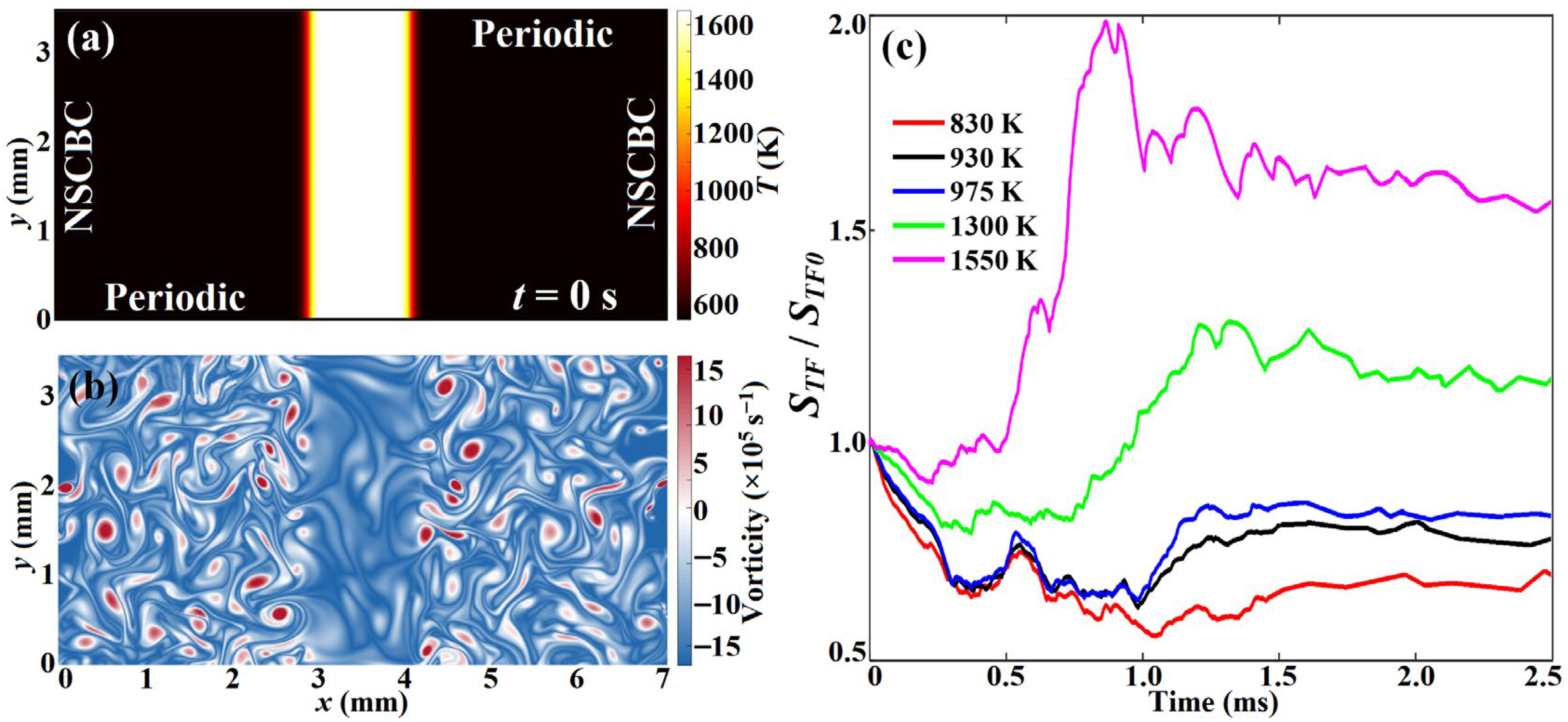
Figure 1. Sketch of the 2D computational domain with the initial temperature (a) and vorticity (b) profiles. The evolutionary development of normalized STF defined based on the progress variable iso-surface with different temperatures (c).
Energies 18 04357 g001
Figure 2. Flame structure of the laminar premixed flamelet (p = 30 atm, T0 = 530 K, ϕ = 0.45) (a), with the local combustion mode distributions shown in (b). The red, green, and gray in (b) depict AUTO, DIFF, and λe ≤ 0, respectively. Species mass fractions and HRR are normalized by their corresponding maxima.
Energies 18 04357 g002
Figure 3. Evolution of flame temperature and HRR in the turbulent combustion condition (t = 0.2~1.5 ms). HRR is normalized by its maxima in the laminar premixed flamelet.
Energies 18 04357 g003
Figure 4. Profiles of the CEM mode eigenvalue (a) and LCMs (b) at t = 0.2, 0.9, and 1.5 ms (from top to bottom). sign(∙) returns the input sign. In the right figures, red, green, and blue represent AUTO, DIFF, and EXTC modes, respectively, with the white pixels satisfying {λe < 0.1} ∩ {(T ≥ 1630 K) ∪ (T ≤ 550 K)}.
Energies 18 04357 g004
Figure 5. PDFs of the normalized HRR (a) and normalized fuel consumption rate (b) conditioned in temperature space. (c) Contributory fractions of HRR and fuel consumption in different temperature ranges in the turbulent and laminar flamelet cases. The black solid and dashed lines represent the conditional mean and flamelet curves, respectively.
Energies 18 04357 g005
Figure 6. PDFs of the normalized heat conduction source (a), and normalized DME (b) and O2 (c) diffusion sources conditioned in temperature space. The black solid and dashed lines represent the conditional mean and laminar flamelet, respectively.
Energies 18 04357 g006
Figure 7. The volume fraction of each LCM conditioned in temperature space. Red, green, blue, and gray represent AUTO, DIFF, EXTC, and POST (λe < 0) modes, respectively.
Energies 18 04357 g007
Figure 8. The JPDF of each LCM conditioned on normalized HRR and normalized fuel consumption rate: (a) DIFF, (b) EXTC, (c) AUTO. (d) Volume fraction of the local dominating LCMs, and the enlarged views of the cool flame subzone (e) and hot flame subzone (f), respectively. Red, green, and blue represent AUTO, DIFF, and EXTC modes, respectively. The black solid and dashed lines represent the conditional mean and laminar flamelet, respectively.
Energies 18 04357 g008
Figure 11. Variations of temperature (row 1), HRR (row 2), and LCMs (row 3) of the sampled propagating cool flames. Columns 1–4 represent line L1 in turbulence, L1 in laminar flamelet, L2 in turbulence, and L2 in the laminar flamelet, respectively. HRRs are normalized by their maxima in the laminar flamelet.
Energies 18 04357 g011
Figure 12. Variations in DIs of the most important diffusion subprocesses (DI > 0.1) along the sampling lines L1 (ac) and L2 (df), respectively. The HRR line color weights the LCM indicator α valuing in the span [−1 1]. Black arrow points to the right vertical coordinate (i.e. Normalized HRR). The meaning of different colored curve are explained in the figure caption.
Energies 18 04357 g012
Figure 13. The thickening process of hot-flame fronts. The cyan, green, and yellow solid lines depict the iso-surfaces of T = 725, 975, and 1100 K, respectively.
Energies 18 04357 g013
Figure 14. Scatters of the normalized HRR during the hot flame thickening process: (a) 1.1 ms, (b) 1.2 ms, (c) 1.3 ms, and (d) 1.4 ms. HRR is normalized by its maxima in the laminar flamelet. The red solid line depicts the laminar flamelet HRR as a function of temperature.
Energies 18 04357 g014
Figure 15. The evolution of LCM during the thickening process of hot-flame fronts.
Energies 18 04357 g015
Figure 16. (a) Variations in DIs for the most important diffusive processes (DI > 0.1), and (b) transport budget analyses in terms of CH2O, H2O2, CH3OCH3, and heat along the cutline L4 at t = 1.2 ms. HRR and heat conduction (CONDHeat) are normalized by the maximum HRR in the laminar flamelet. The ROP and diffusion flux (DIF) for a specific species are normalized by its maximum absolute ROP. The black arrow points to the right vertical coordinate (i.e. Normalized HRR).
Energies 18 04357 g016
Disclaimer/Publisher’s Note: The statements, opinions and data contained in all publications are solely those of the individual author(s) and contributor(s) and not of MDPI and/or the editor(s). MDPI and/or the editor(s) disclaim responsibility for any injury to people or property resulting from any ideas, methods, instructions or products referred to in the content.