1. Introduction
Transmission network planning is essential for ensuring grid reliability and meeting future demand. It involves optimizing line capacities and network layout while balancing reliability and economic performance. Considering the high costs associated with constructing new substations, well-planned network development can significantly reduce investment and enhance overall system efficiency [
1]. Artificial intelligence algorithms have found successful applications in various fields, including power system planning and operation, where they can enhance decision-making accuracy and computational efficiency [
2,
3].
In the current global economic climate, which is characterized by slow economic growth and mounting domestic challenges, the transformation and upgrading of the electric power system must consider economic factors more comprehensively. The uncertainties associated with these factors create significant challenges in the renovation and planning of power transmission networks. Traditional approaches, such as building new substations, are increasingly unfeasible due to escalating costs. As a result, more advanced and flexible planning strategies are required to adapt to the evolving demands of the energy sector and industry, especially considering the popularization and construction of new energy access and smart grids [
4,
5,
6,
7].
Historically, the renovation of transmission networks involved constructing substations at higher or equivalent voltage levels and linking them to form a meshed network, thereby enhancing reliability. However, this approach incurs high costs, particularly for non-critical loads, and offers limited flexibility to accommodate new power sources. Given the rising need for adaptable and efficient power systems, there is an increasing demand to explore innovative methods for transmission network transformation [
8,
9,
10,
11,
12,
13].
A promising approach involves integrating voltage regulation techniques from distribution networks into transmission planning models. This integration can enhance the flexibility and adaptability of the planning process, making it easier to manage peak load conditions and improve overall system reliability. For instance, during periods of high air-conditioning demand in summer, the power-side capacity of existing 110 kV transmission lines—specifically, the outgoing feeders on the low-voltage side of upstream substations—may become insufficient. In such cases, adding standby transmission lines becomes critical to ensuring a reliable power supply [
14].
As the development of microgrids and active distribution networks progresses, optimizing the placement and operation of distributed energy resources (DERs) becomes increasingly important for enhancing the efficiency and sustainability of modern power systems [
15,
16,
17,
18,
19,
20]. The growing integration of DERs into smart microgrids presents new challenges, particularly in optimizing the placement of battery storage systems (BSSs). Recent work has proposed hybrid optimization strategies that combine multiple approaches to address these challenges, improving both technical performance and operational costs [
21].
Recent studies emphasize the importance of network observability for effective grid management, particularly with the rise of distributed generation. Novel methodologies for the optimal placement of Phasor Measurement Units (PMUs) have been proposed, utilizing centrality measures and contingency analysis to improve monitoring while reducing the number of PMUs required for full observability [
22]. Moreover, mobile energy storage systems (MESSs) have been proposed as an effective solution to address the operational challenges posed by offline-controlled (without SCADA) photovoltaic (PV) systems, by enabling optimized power flow coordination and curtailment minimization through mixed-integer linear programming (MILP) techniques [
23]. Efforts to minimize power losses and enhance voltage stability in distribution networks have also focused on optimizing the operation of devices such as DSTATCOMs and integrating renewable sources like PVs [
24]. Furthermore, as renewable energy sources introduce variability, advanced optimization models, including those utilizing machine learning techniques like Long Short-Term Memory (LSTM) and Particle Swarm Optimization (PSO), have been developed to improve the operational flexibility of traditional power plants [
25].
The integration of solar and wind power into hybrid systems, along with strategies for optimal reconfiguration and power flow management, is also a growing area of research. These methods aim to reduce energy curtailment and improve the overall stability and efficiency of power systems with high renewable penetration [
26,
27,
28,
29,
30,
31]. Additionally, addressing voltage unbalance and enhancing transient stability in the face of distributed generation have led to the development of new multi-objective optimization models and control strategies [
32,
33].
This study contributes to the ongoing research by proposing a flexible transmission network planning model that integrates economic and technical considerations. The model incorporates voltage regulation techniques from distribution networks to improve the adaptability of high-voltage transmission networks. We focus on key metrics such as power losses, voltage amplitude deviations, and voltage imbalances to assess the model’s effectiveness in enhancing voltage stability. Moreover, this study discusses operational and backup strategies for high-voltage lines, particularly for critical load-side substations, to mitigate the risk of load loss during periods of high demand. By selecting appropriate backup power sources, we aim to improve the reliability of power supply while minimizing construction costs. This approach presents a significant advancement for power system planning, offering a more flexible, cost-effective solution to the challenges posed by increasing demand and integration of renewable energy sources.
2. Methodology
2.1. Transmission Line Module
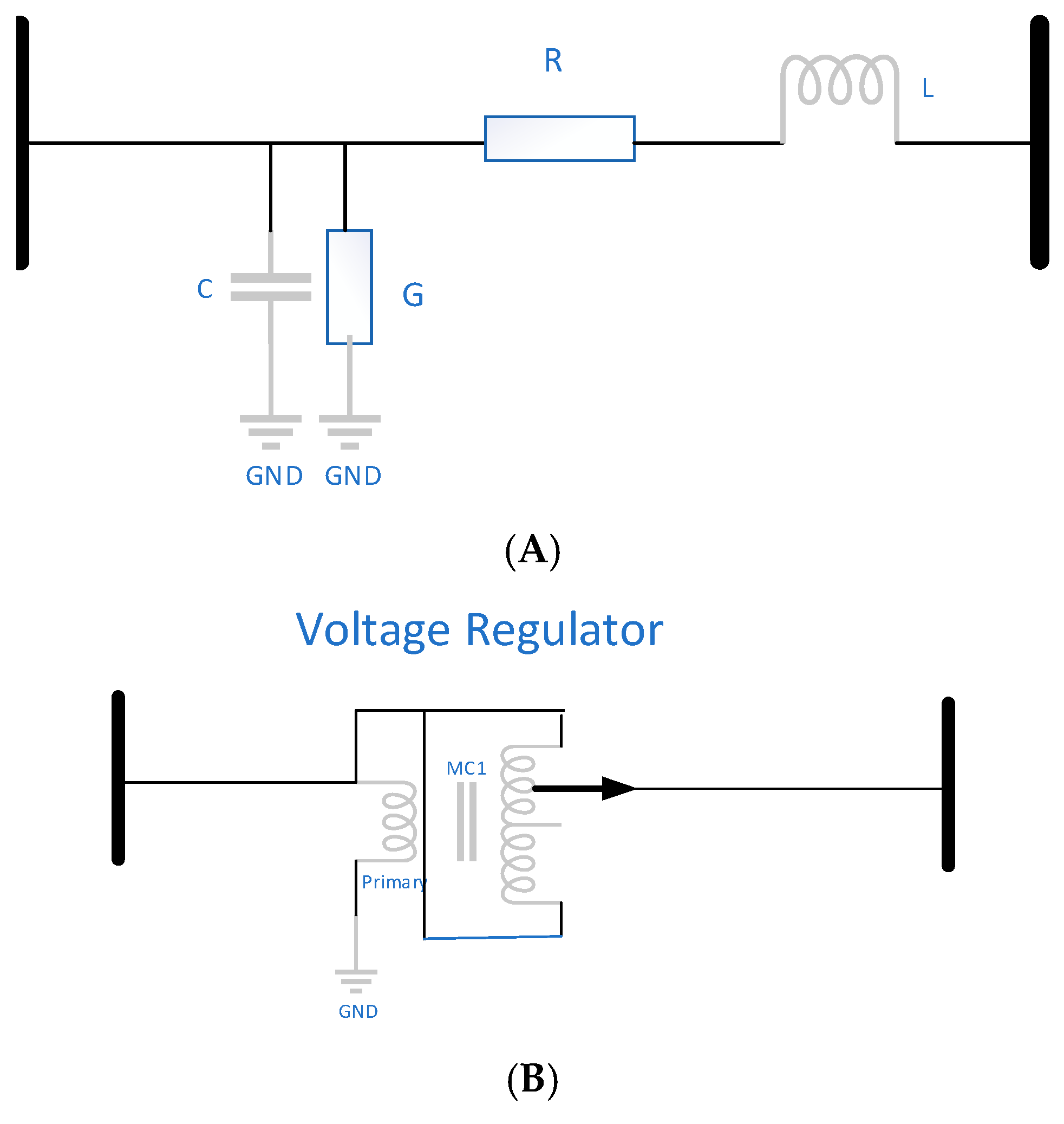
Transmission lines are typically characterized by their resistance and inductance per unit length, as well as their capacitance and conductance to ground per unit length. According to the regulations set by the State Grid Corporation of China, transmission lines shorter than 500 km are generally analyzed using lumped parameters. Therefore, the transmission line model presented in
Figure 1A adheres to these standards [
34,
35].
For the newly added backup transmission line, its extended length requires the consideration of a voltage regulator placed at the midpoint of the line. A model of this setup is shown in
Figure 1B [
36].
2.2. Multi-Objective Optimisation Model
When formulating the Optimal Power Flow (OPF) problems for distribution network grids, five distinct objective functions (OFs) are considered. Due to the unbalanced nature of the system, each phase must be addressed with its own set of objective functions. In the following equations, the variable “p” represents the phase. The notation for both node number and phase is used to specify a node . Specifically, indicates node i of phase A, refers to node i of phase B, denotes node i of phase C. Here, Fn represents the objective function, where n is the number of the OF.
2.2.1. Active Power Loss
Equation (1) can be used to calculate the power losses in the transmission lines:
2.2.2. Load-Side Voltage Magnitude Deviation
According to the execution standard of the State Grid Corporation of China, “Allowable Deviations in Voltage Supply for Electric Energy Quality” (GB12325-2003) [
37], the cumulative absolute value of the positive and negative deviations in supply voltage at 35 kV and above must not exceed 10% of the nominal system voltage. Consequently, the three-phase voltage entering the 110 kV substation at the terminal end of this transmission line must comply with this standard to ensure the 110 kV bus voltage at the substation remains within permissible limits. This is crucial to prevent the voltage from being excessively high or low, which could adversely affect the power transmission capabilities of the main transformers and subsequent distribution lines.
can receive one of the following values:
2.2.3. Voltage Unbalance Factor
Three-phase voltage unbalance occurs when there are differences in voltage magnitudes or phase angles across the phases, often due to uneven load distribution. This imbalance can have significant negative effects on the power system. It typically results from voltage asymmetry in each phase of the three-phase supply, which is mainly caused by imbalanced load distribution. The degree of imbalance depends on factors such as the configuration of the load, the characteristics of user loads, and how the system’s loads are planned and distributed. According to the “Permissible Unbalance of Three-Phase Voltage in Power Quality” standard (GB/T15543-1995) by the State Grid Corporation of China, voltage imbalance at the point of common coupling (PCC) is mainly attributed to the negative sequence component during normal system operation [
38]. This standard sets the maximum allowable voltage unbalance at the PCC to 2% under normal conditions, up to 4% for short durations. Negative sequence voltage and current contribute to additional losses in transformers, including no-load and load losses, which can significantly damage the equipment. Transformer operation guidelines specify that the neutral current should not exceed 25% of the rated current on the transformer’s low-voltage side. Additionally, unbalanced operation of three-phase loads can lead to excessive zero-sequence currents, increasing the temperature of localized metal parts and potentially causing transformer failures. The voltage unbalance factor can be calculated using the following formula:
To improve the voltage profile and make it more balanced,
is defined in (5):
where
is the permissible value of the VUF.
2.2.4. Construction Cost of Substation or Transmission Line
Substation construction requires significant investment. A 220 kV substation costs around CNY 0.8–1 billion (approximately USD 0.11–0.14 billion), while a 110 kV substation costs about CNY 500 million (approximately USD 69.4 million). The construction of 220 kV substations takes at least three years, with costs often exceeding CNY one billion (approximately USD 0.14 billion). In contrast, building or upgrading overhead transmission lines is less expensive, at about CNY 150 thousand (approximately USD 20.83 thousand) per kilometer and can be completed in around three months. Therefore, both cost and construction time are key factors in evaluation.
2.2.5. Economic Losses Caused by the Loss of Critical Loads
With rising demand for power reliability, extreme scenarios must be considered where a single 110 kV transmission line feeds two buses, all main transformers, and their loads. Substation transitions should be completed within an hour to prevent complaints. When reliability is low and critical users’ power cannot be quickly restored, emergency power generation vehicles must be deployed, leading to significant losses for the power company. The cost of using these vehicles is as follows
2.2.6. Multi-Objective Function
In summary, the multi-objective optimization objective function can be formulated as follows:
where
represents the fundamental scale, aiming to equalize the values of each objective function.
Concurrently, Equation (10) transforms the optimization objective into a convex optimization problem [
39].
2.2.7. Equality Constraint
For power flow in electrical systems, it is necessary to satisfy the balance conditions of active power and reactive power:
2.2.8. Voltage Inequality Constraint
For nodes at the power source and load ends within the system, their voltage magnitude must fall within the specified range. Particularly, strict control is necessary for the voltage at the power source end. If it is arbitrarily increased, there is a high probability of causing excessively high voltages when shorter transmission lines on the medium-voltage side reach their load-side substations:
2.2.9. Apparent Power Magnitude Range Constraint
From the perspective of the power source-side substation, the loads and losses of multiple lines must be within the apparent power capacity range of the main transformer on this side:
2.2.10. The Constraint on Maximum Current Flow Through the Line
Each transmission line is subject to material constraints, with an upper limit on the current it can carry; otherwise, fire accidents may occur.
2.3. Deep Q-Learning
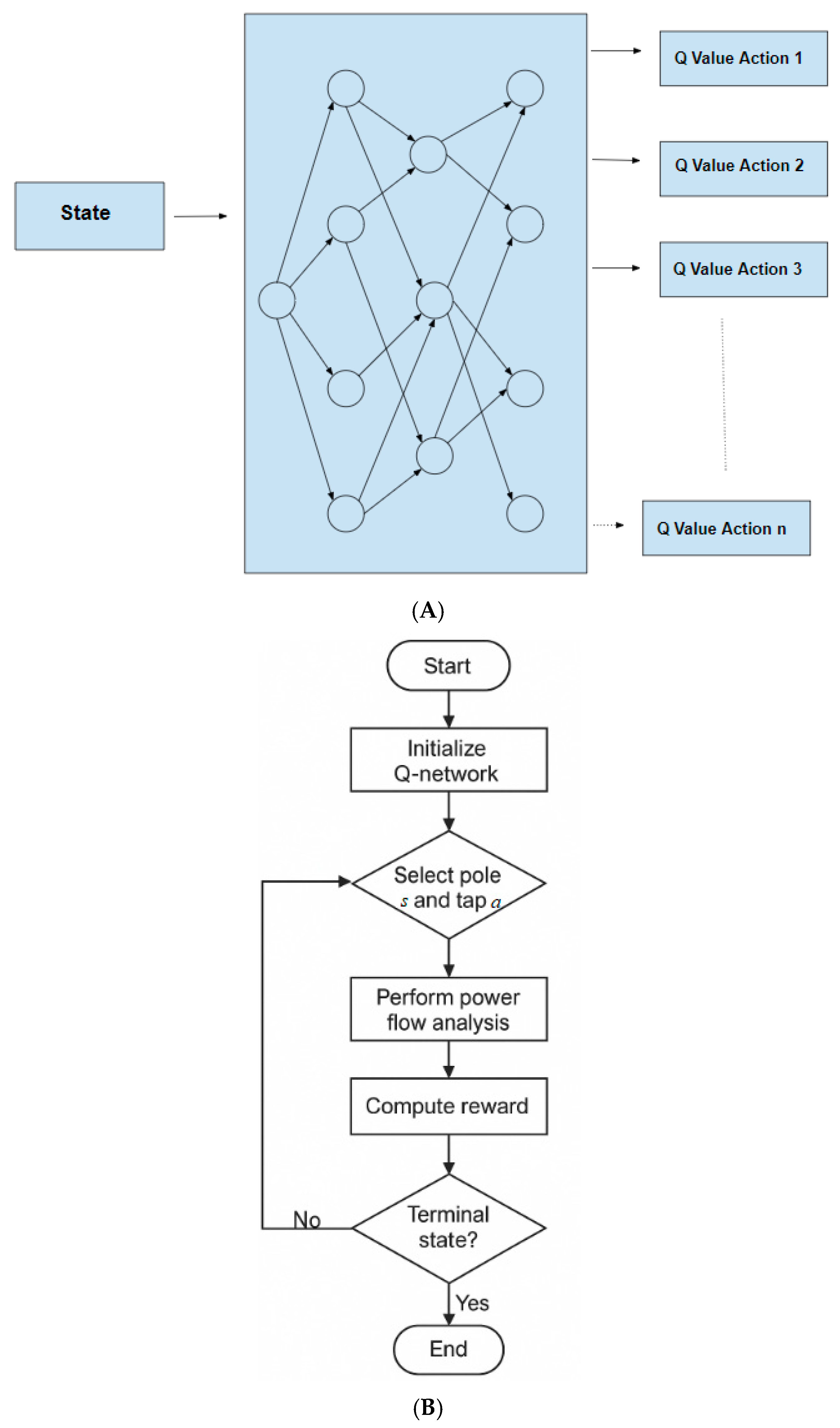
Deep Q-Learning (DQL) is a reinforcement learning technique that employs a deep neural network to approximate the Q-function, which represents the expected cumulative reward obtained by taking a particular action in a given state under a specific policy. Unlike traditional tabular Q-Learning methods, DQL enables the handling of high-dimensional and continuous state-action spaces, making it well suited for complex engineering problems such as voltage regulator deployment in transmission networks [
40].
In the context of this study, a DQL-based framework is developed to determine the optimal placement and tap setting of voltage regulators along long-distance transmission lines. The associated decision-making process is illustrated in the proposed flowchart, where the state variable s represents the index of the transmission tower under consideration for regulator installation, and the action variable a corresponds to the tap position selected for that regulator. The algorithm interacts iteratively with a simulated environment, updating the Q-function based on observed rewards, which are designed to reflect reductions in power loss, voltage deviation, and imbalance.
The Q-function is updated using the following target formulation:
It is important to note that the term γ max_{a’}Q_{k}(s’,a’) is variable.
In contrast to traditional methods with fixed-target values, this process uses a dynamic target. Two models are used: one updates parameters iteratively, while the other, with the same structure but fixed parameters, computes the target. Unlike conventional fixed-target approaches, this formulation employs a dynamic target using two neural networks: one that continuously updates parameters through training, and another that temporarily holds fixed parameters to stabilize target estimation. After a specified number of iterations, the parameters of the primary Q-network are copied to the target network.
In engineering terms, this learning mechanism parallels the real-world constraints of power system planning. Voltage regulators must be installed only at existing tower locations, and substations must avoid sensitive urban or agricultural zones. This setup constitutes a Mixed-Integer Nonlinear Programming (MINLP) problem, where discrete variables (e.g., regulator locations) and continuous variables (e.g., tap settings) are jointly optimized. By formulating tower indices and tap positions as control variables within the DQL framework, the proposed method enables a data-driven and highly adaptable strategy for improving system-wide voltage quality and minimizing energy loss with superior computational efficiency (
Figure 2).
3. Results
3.1. Substantiation and Transmission Lines
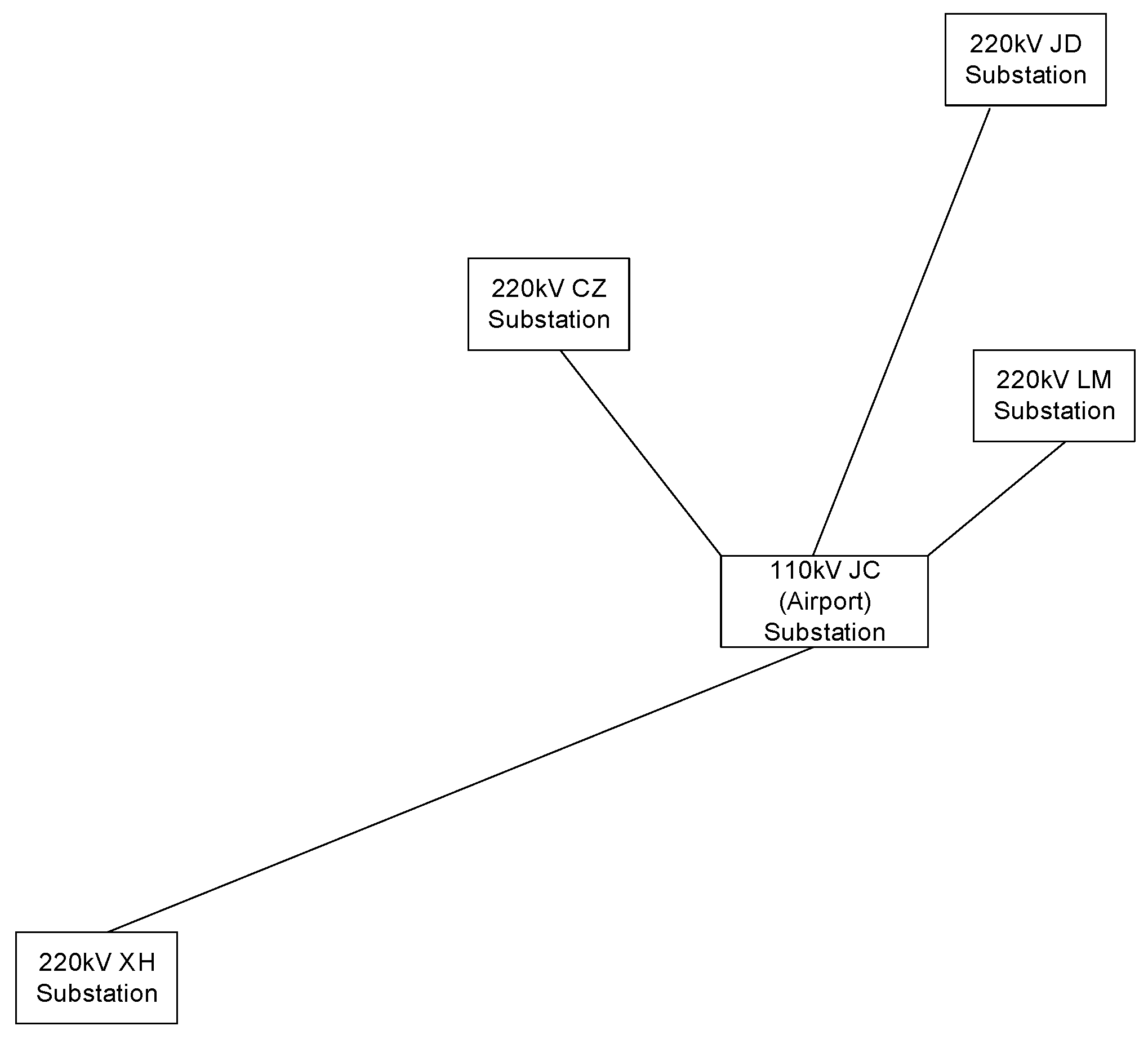
This study examines two 110 kV transmission lines owned by the State Grid Zhengzhou Power Supply Company, located in the southwestern region of Zhengzhou. The analysis focuses on four 220 kV substations and one 110 kV substation. The CZ Substation, situated on the southeastern outskirts of Zhengzhou, operates at 220 kV. The LM Substation, recently constructed in Xinzheng County, is approximately 10 km from the Airport Substation. The XH Substation lies within Dengfeng County, in the southwestern part of the Zhengzhou region. Additionally, the JD Substation, about 60 km from the Airport Substation, is located on the city’s outskirts and relies on long-distance transmission lines (
Figure 3).
All these substations are categorized as 220 kV high-voltage centralized substations. The Airport Substation is pivotal as the primary power source for Zhengzhou Xinzheng International Airport, serving as a critical 110 kV electrical substation. Classified as a medium-voltage substation, it plays a significant role in high-voltage power distribution in the vicinity of Zhengzhou Xinzheng International Airport. Furthermore, its 110 kV bus supplies power to industrial high-voltage users with their own 110 kV substations in the surrounding area.
3.1.1. Two 110 kV Backup Power Supply Lines
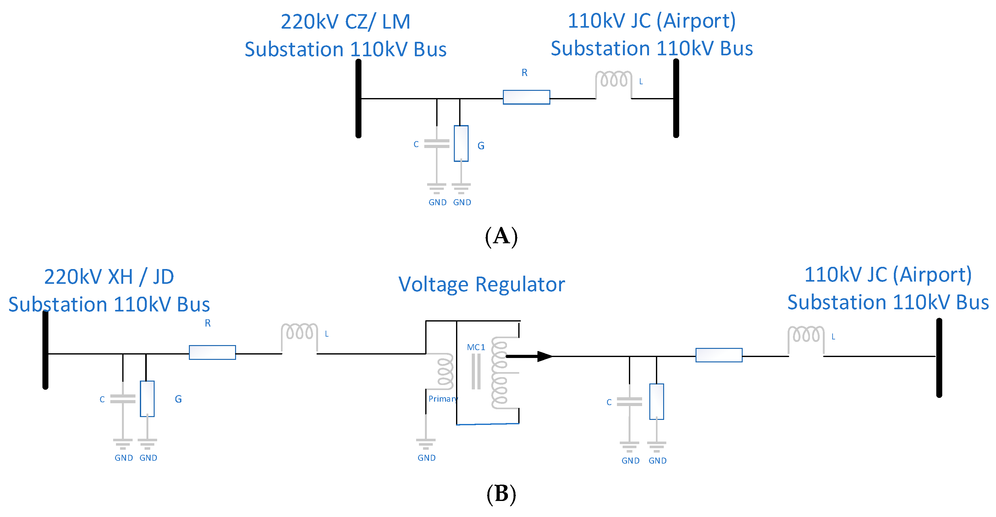
The C-J transmission line, a 22 km 110 kV line, starts at CZ Substation and ends at JC (Airport) Substation. It is connected to the 220 kV system and carries significant load, with two 110 kV transformers, resulting in notable transmission losses. The X-J and J-J lines are hypothetical, assumed to connect the XH or JD Substation directly to the JC Substation with a voltage regulator for reactive power control. We aim to calculate the voltage level at the JC Substation and transmission losses. New lines of 65 km and 30 km are needed, but due to terrain features, the actual distances are assumed to be 70 km and 40 km. The 110 kV XJ and JJ lines can be modified using sections of existing lines, with modification lengths of 35 km and 15 km, respectively. The modification cost is estimated at CNY 100,000 per kilometer (
Figure 4,
Figure 5 and
Figure 6).
This study will focus on analyzing the electrical energy losses, terminal voltage levels, voltage imbalance, and other key power quality indicators under two extreme scenarios: each of the two farther substations individually connecting to one bus of the Airport Substation and the farthest XH Substation connecting to all three main transformers of the 110 kV JC (Airport) Substation. The scenarios considered include the JJ Line (with voltage regulator), the XJ Line (with voltage regulator), and the XJ Line (with voltage regulator) supplying the entire Airport Substation. The objective is to identify the optimal location for installing voltage regulators or constructing new substations and subsequently determine the best construction plan, taking into account the construction costs of the 220 kV substations or the 110 kV transmission lines.
3.1.2. A Split Operation Mode Approaching the Normal Operation Mode
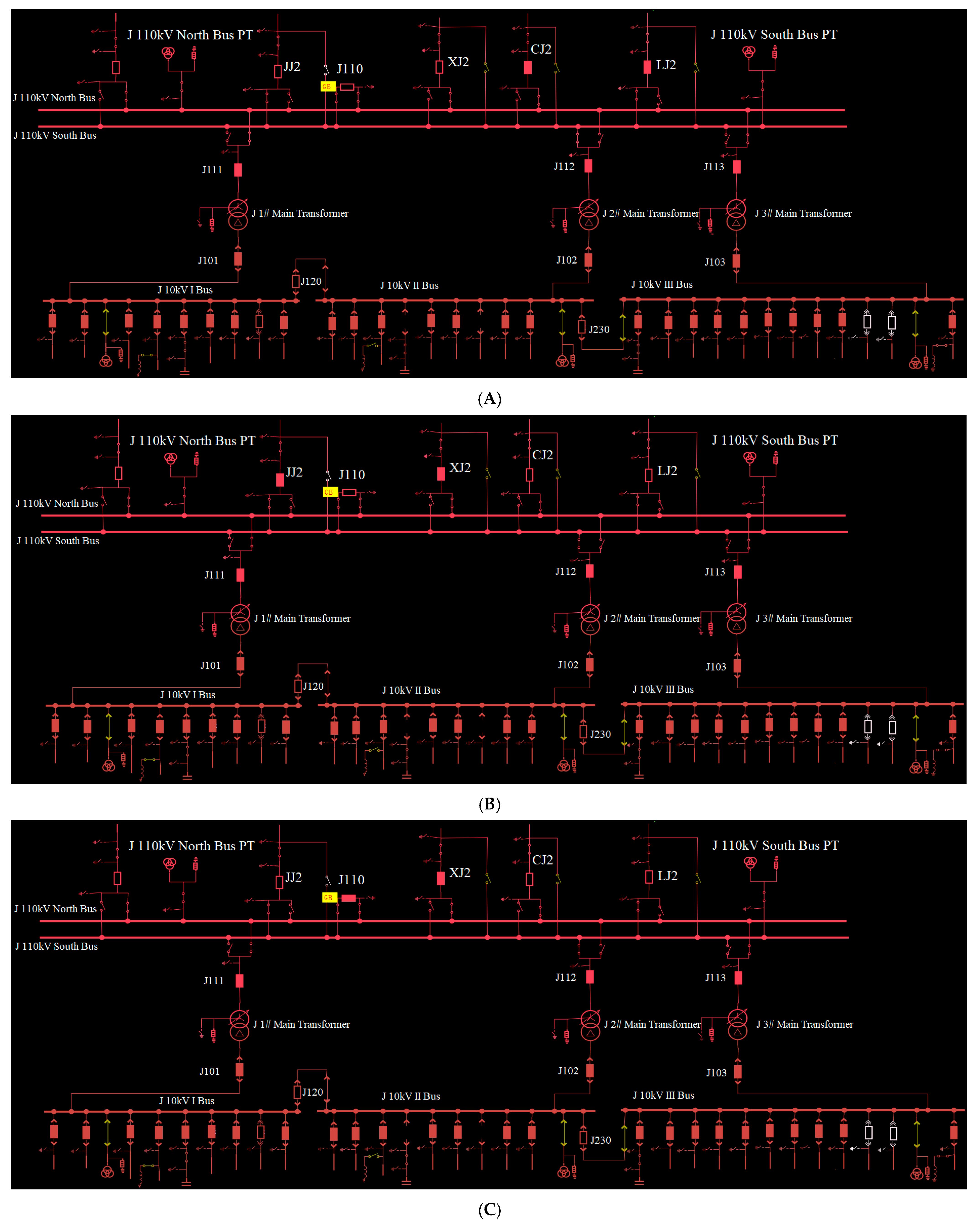
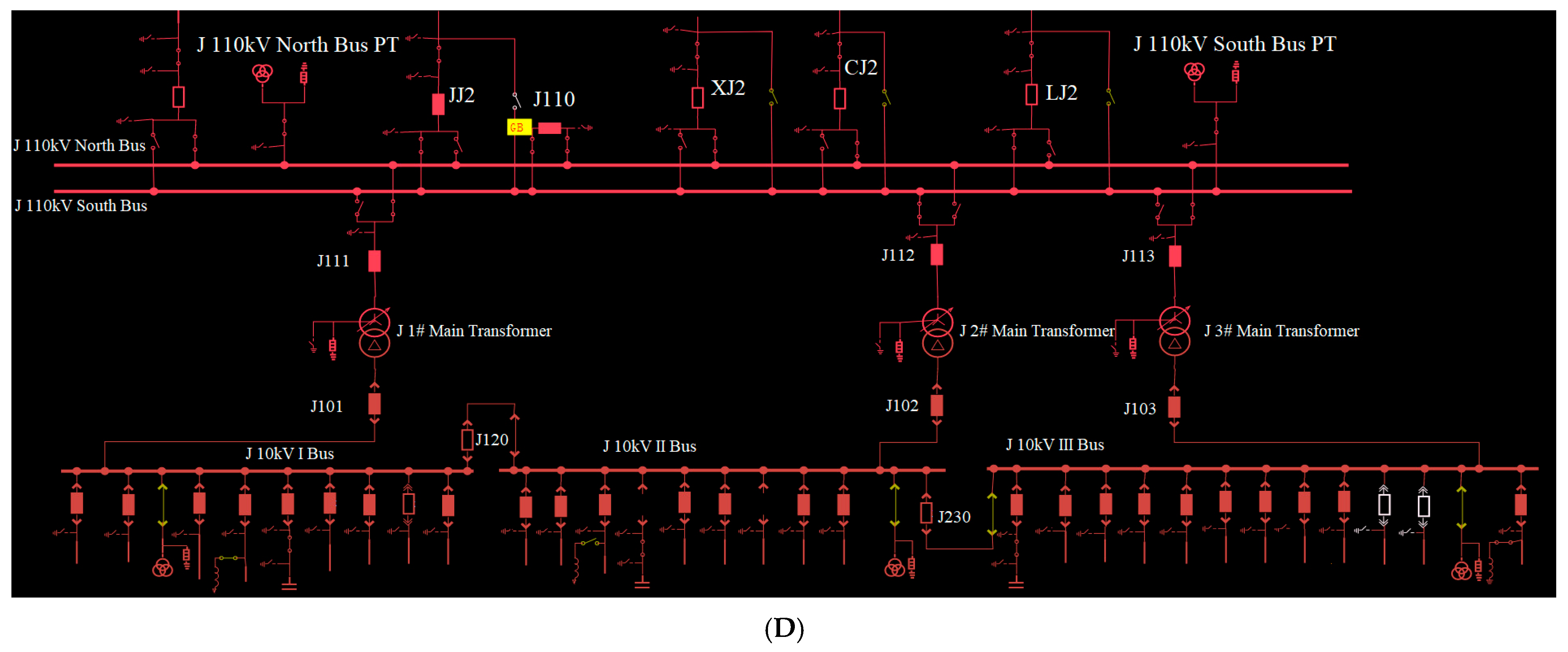
In normal operating conditions, the 110 kV CJ transmission line feeds the J 110 kV north bus, while the 110 kV LJ transmission line powers the JC (Airport) 110 kV south bus. The JC (Airport) 110 kV north bus supplies the 110 kV JC (Airport) 1# and 3# main transformers, while the 110 kV JC (Airport) south bus provides power to the 110 kV JC (Airport) 2# main transformer. The 110 kV bus-tie circuit breaker J110 is open, causing the two bus sections to operate independently. It is important to note that the red rectangles in
Figure 7A–D represent circuit breakers, not resistors.
It should be noted that both the 220 kV XH Substation and the 220 kV JD Substation are equipped with two main transformers, each with a capacity of 240 MVA. These transformers are capable of supplying all 110 kV and 10 kV loads within their respective substations. As a result, the 110 kV JC (Airport) Substation is effectively connected to an infinite system, without any limitations on the active and reactive power it can supply.
3.1.3. Scenario 1: A Split Operation Mode Approaching the Normal Operation Mode
In this case, the 110 kV northern bus at the JC (Airport) Substation is powered by the 110 kV outgoing line from the 220 kV XH Substation, while the 220 kV JD Substation provides power to the northern bus through its own 110 kV outgoing line. Both supply lines cover long distances. To ensure voltage remains within acceptable limits at both the source and load ends, voltage regulators need to be installed on the transmission line towers. Optimization calculations will help identify the most effective locations for these regulators and evaluate the voltage and power conditions at both ends.
3.1.4. Scenario 2: The Operational Mode in Which the Entire 110 kV JC (Airport) Substation Is Powered by the 220 kV XH Substation
In this operational setup, the 110 kV Airport Substation is supplied by a single power source from the 110 kV XJ line. The 110 kV JC (Airport) circuit breaker is closed, and the 110 kV south and north buses are interconnected. The 220 kV XH Substation serves as the only power supply for the 110 kV JC (Airport) Substation.
3.1.5. Scenario 3: The Operational Mode in Which the Entire 110 kV JC (Airport) Substation Is Powered by the 220 kV JD Substation
In this operating mode, the 220 kV JD Substation provides the only power supply to the 110 kV JC Substation. The 110 kV JJ transmission line delivers power to the 110 kV JC Substation. The J110 circuit breaker connects the two buses for coordinated operation.
3.1.6. Weight Selection for Sub-Objective Optimization Functions
Given the current economic climate, the growing influence of online public opinion, and the increasing demand for reliable power supply, all five sub-objectives are of critical importance. As a result, each has been assigned a weight of 0.2 (
Table 1).
3.2. Optimal Placement of the Voltage Regulators
The distance between towers on the 110 kV transmission lines is approximately 100 m. With this assumption, the 110 kV XJ line contains a total of 751 towers along its entire length, while the 110 kV JJ transmission line has 401 towers.
The current conditions, including line losses, voltage deviations, and imbalance, are used as benchmarks. Additionally, the construction cost of a new substation and the operating costs of generation units, which are impacted by the need to shut down part of the load during peak summer demand, are also taken into account. By optimizing the objective function, the best solution is identified by determining the optimal locations for installing voltage regulators on backup lines, ultimately guiding the best course of action.
Through computational analysis, optimal performance is achieved when voltage regulators are positioned at approximately 45% of the total length of the transmission lines. In this configuration, only two transmission lines need modification, eliminating the need for new substations. If a system operational adjustment is required, a complete scheme can be developed, and the system can be reconfigured within 60 min.
In a scenario where two long-distance 110 kV transmission lines supply power to the 110 kV Airport Substation in parallel, the optimal position for voltage regulators differs by about 5 km compared to a scenario where a single line supplies power to the entire substation. Given the increased risk of relying on a single-source power supply, which is not sustainable over extended periods, the optimal installation position from the parallel operation of the two long lines should be adopted as the final installation point.
When a single line is required to supply power to the entire 110 kV JC (Airport) Substation, the voltage regulator tap position must be adjusted accordingly. Details of the adjustment units are provided in
Table 2 and
Table 3.
3.3. Power Loss
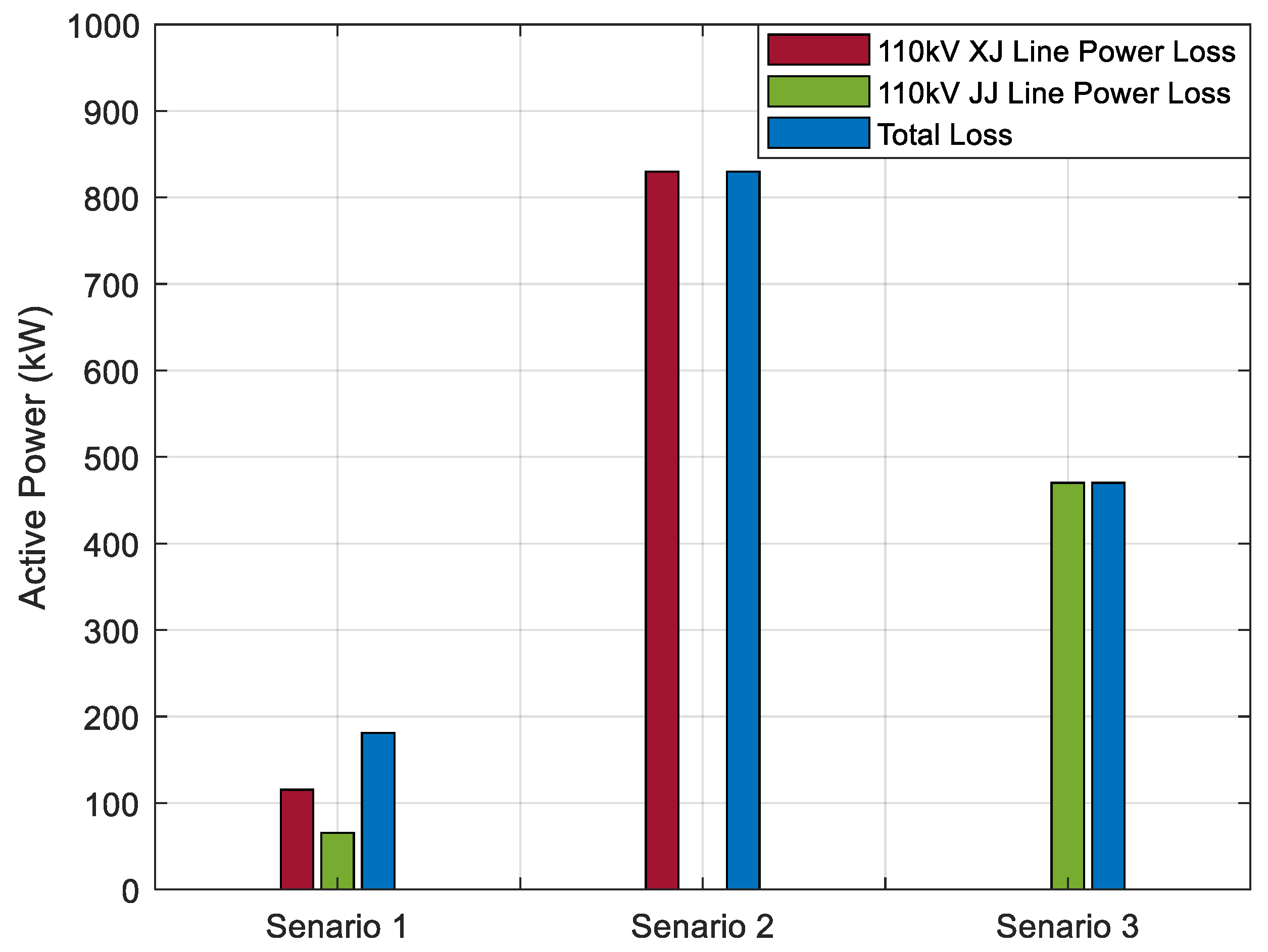
As illustrated in
Figure 8, when the 110 kV JC (Airport) Substation is fed via a single long-distance transmission line, the system experiences a marked increase in line losses. The integration of a voltage regulator effectively limits these losses to below 1000 kW, a level considered economically justifiable relative to the associated capital investment. Furthermore, when two 110 kV long-distance lines operate in parallel, the resulting transmission losses are considerably reduced compared to the single-line configuration.
3.4. Voltage Quality
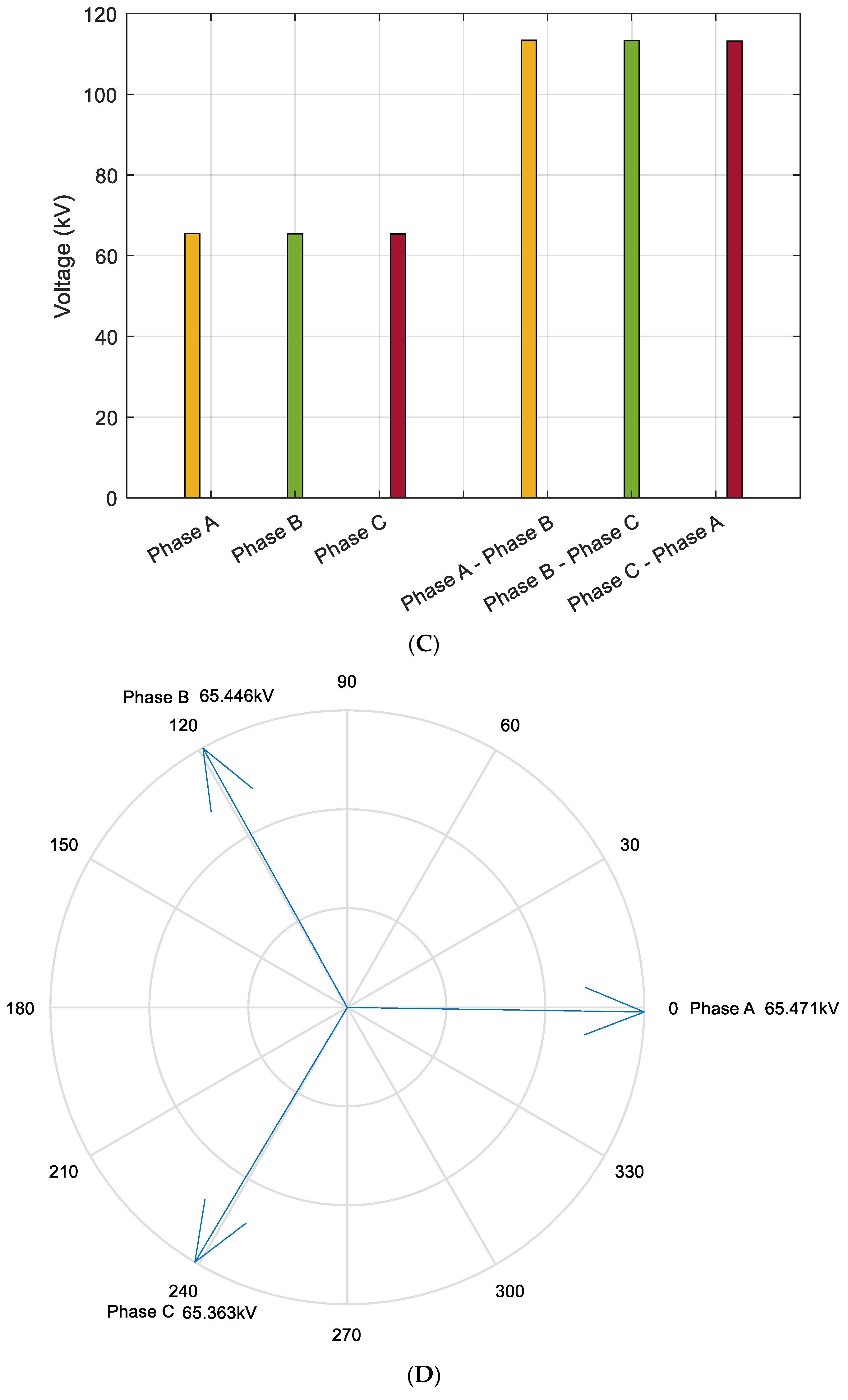
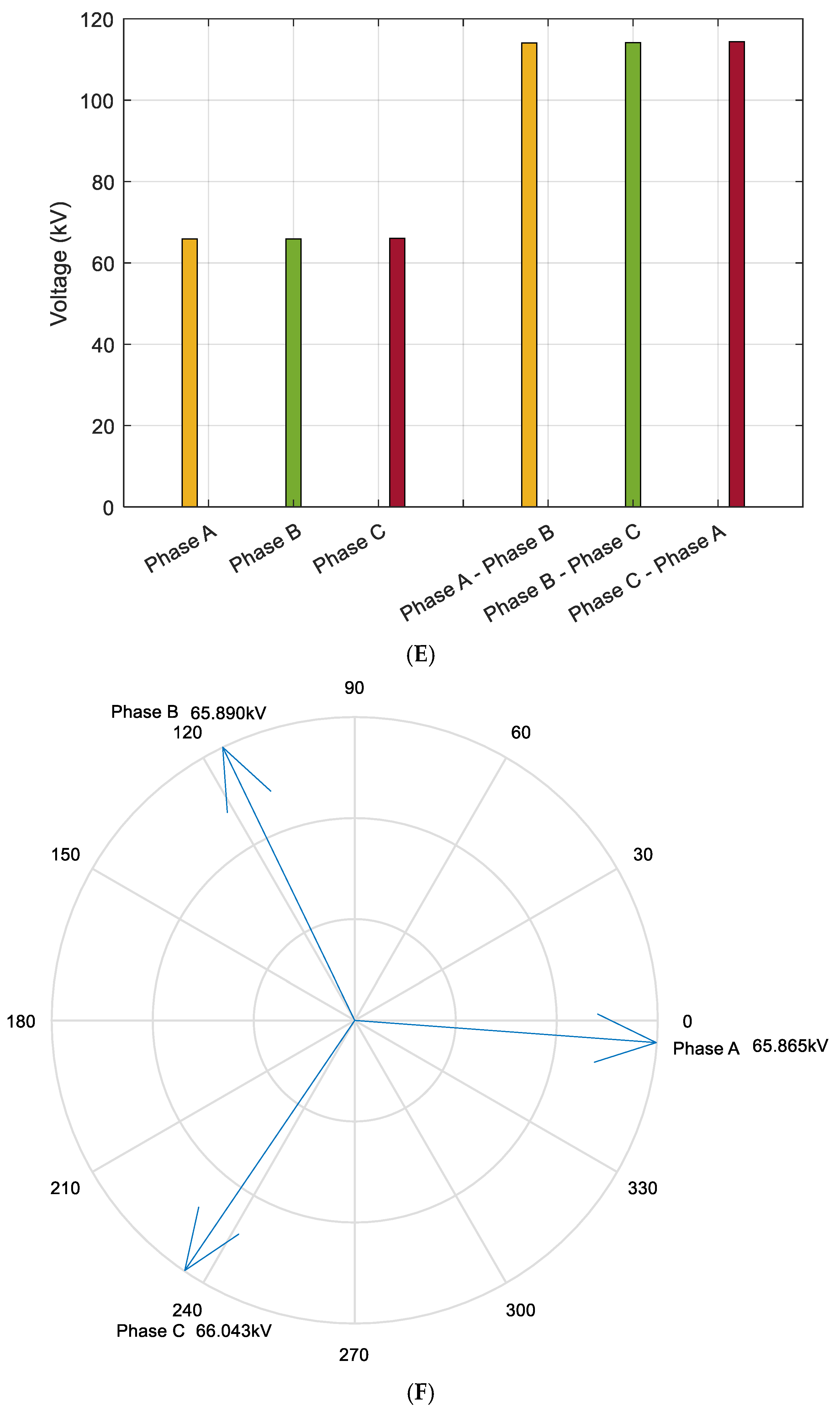
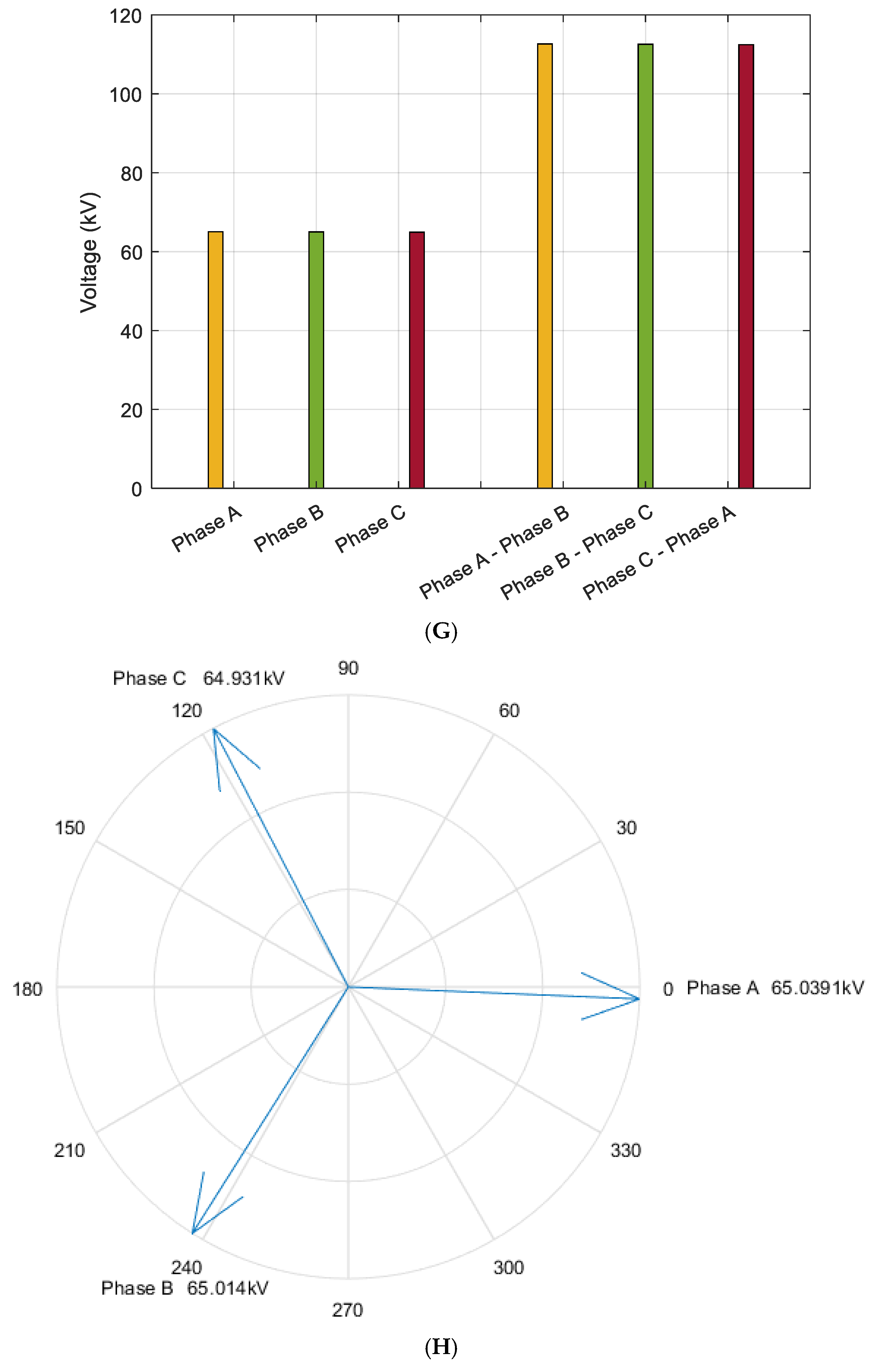
As illustrated in
Figure 9A–H, the voltage magnitude at the 110 kV busbar on the source side of the 220 kV XH and JD Substations shows minimal deviation from that of the load-side 110 kV busbar at the JC (Airport) Substation. This voltage stability is primarily attributed to the regulating function of the on-load tap-changing (OLTC) voltage regulator.
By maintaining a stable voltage profile, the regulator effectively reduces the load current, thereby suppressing active power losses along the transmission corridor. The reduction in voltage differential between the sending and receiving ends not only minimizes line losses but also improves voltage quality at the receiving terminal. The siting of the voltage regulator and the determination of its tap settings are guided by the principle of voltage drop compensation.
With increasing transmission distance, the required tap adjustment range must be widened to offset larger voltage drops, which consequently induces greater variation in the voltage phase angle at the load side. Under high-load operating conditions, this effect is further amplified, necessitating deeper tap operations and resulting in more significant phase angle deviations at the terminal busbar.
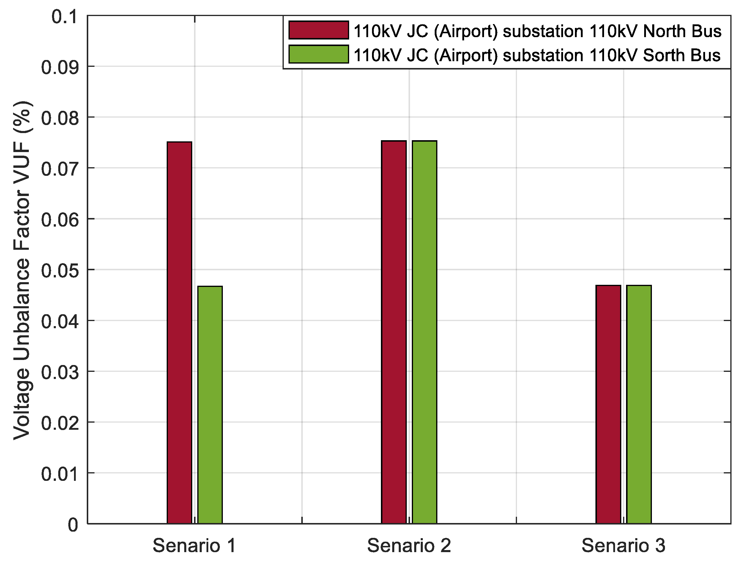
Figure 10 illustrates that, although voltage imbalance exists at the 110 kV bus on the supply side of the 220 kV XH and JD Substations—primarily due to system asymmetry and unbalanced loads—the voltage regulator installed along the transmission line effectively suppresses this issue. The voltage unbalance at the 110 kV bus of the JC (Airport) Substation remains well below the maximum allowable threshold of 2%, confirming the regulator’s significant contribution to power quality improvement, particularly in maintaining voltage symmetry and stability at the load end.
3.5. Power Delivery
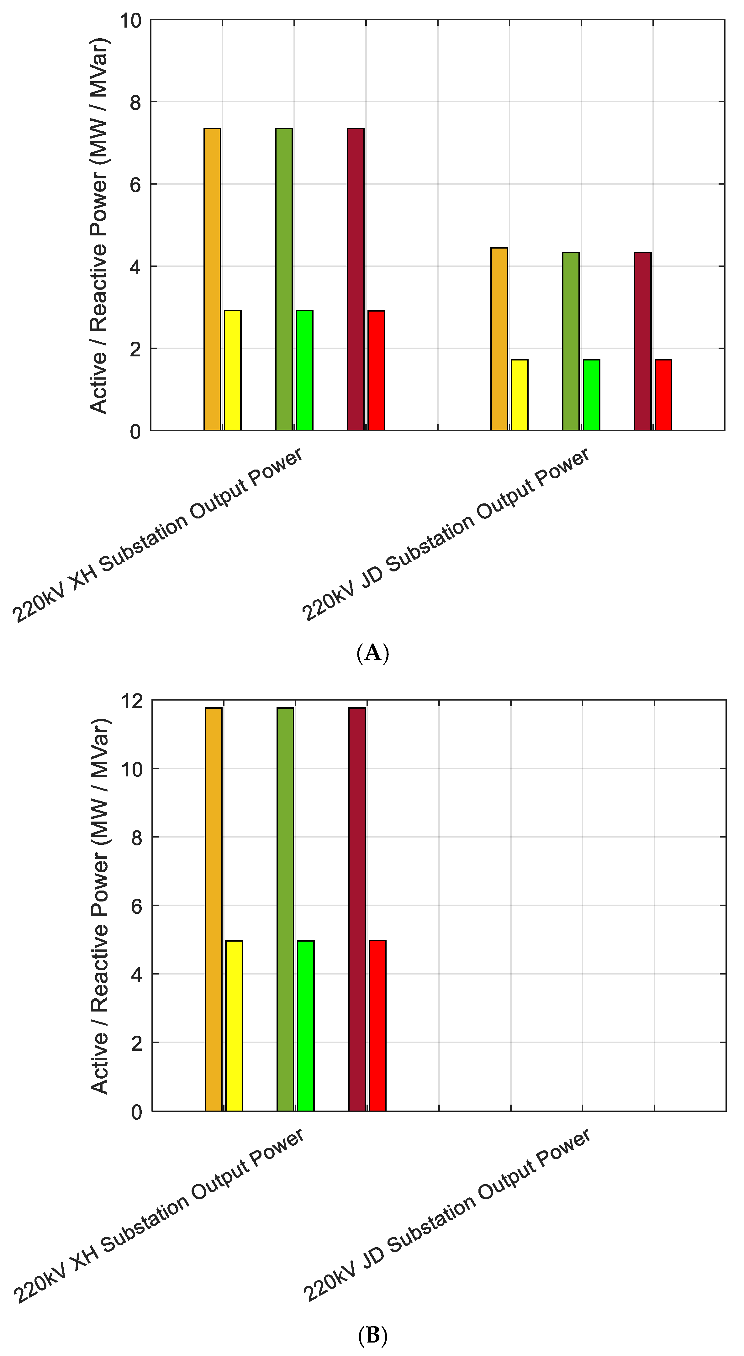
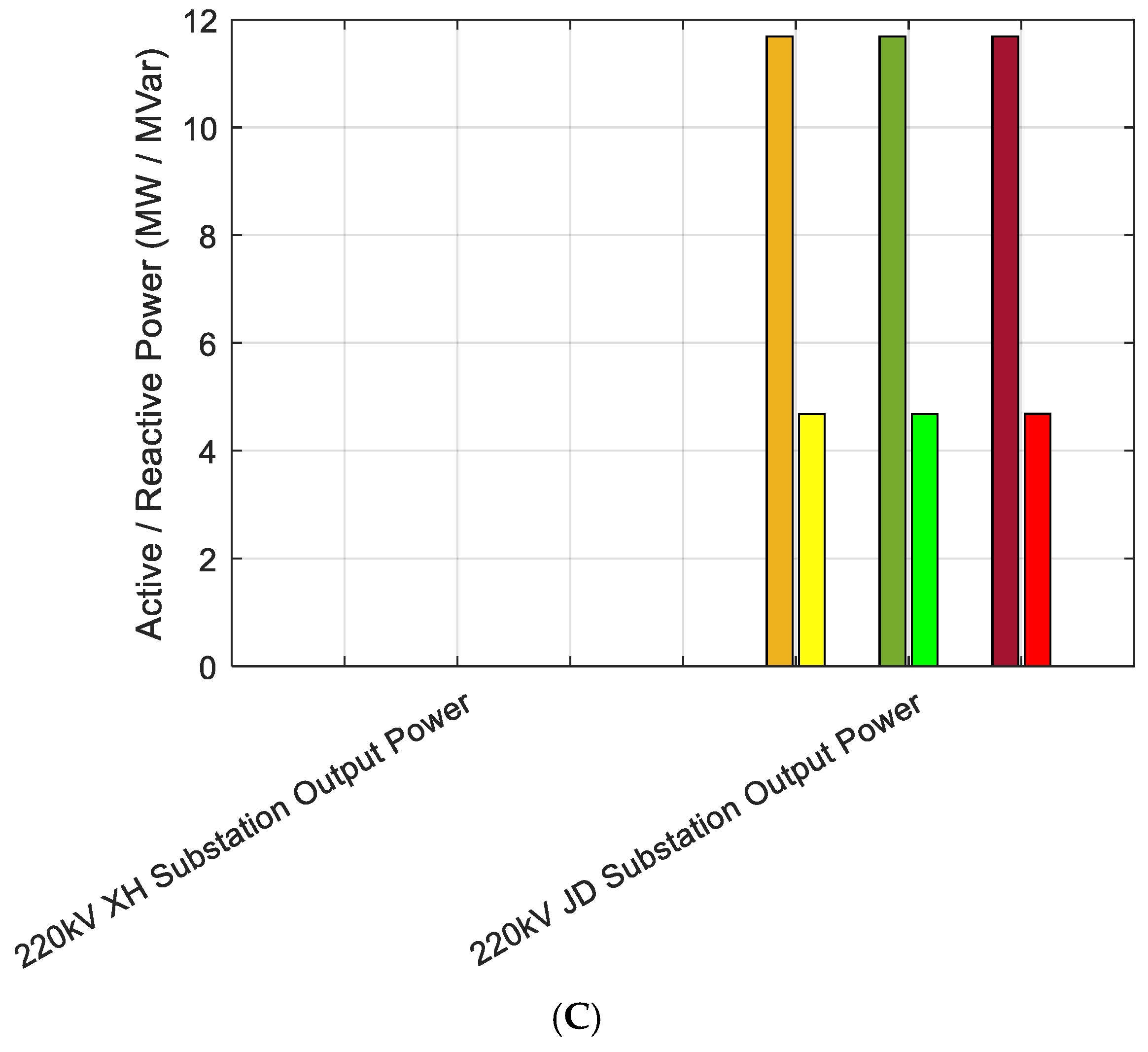
Figure 11A–C demonstrate that, although transmission losses exhibit noticeable variation with changes in line length, the deployment of voltage regulators ensures that these losses remain relatively constrained in proportion to the terminal load demand. This containment effect helps maintain power output deviations at the sending end within an acceptable operational margin. Voltage regulators themselves do not inject active or reactive power into the system; rather, they modify the voltage profile along the transmission corridor, thereby influencing the spatial distribution of both active and reactive power flows. This facilitates localized power flow control and enhances system voltage stability without requiring an additional power injection.
Furthermore, across various network configurations and operating conditions, the total active and reactive power supplied by the sending-end substations remains nearly constant. The slight differences observed stem mainly from transmission losses associated with varying line lengths. However, given the relatively small magnitude of these losses compared to the total load at the receiving end, their impact is not visually significant in the presented figures. This further validates the effectiveness of voltage regulation in mitigating distance-induced power transfer inefficiencies while preserving source-side power balance.
3.6. Economic Factor
3.6.1. Economic Comparison Between Transmission Line Relocation and New Substation Construction
The 110 kV XJ and JJ lines are scheduled for modification and relocation by repurposing segments of the existing transmission infrastructure. The planned adjustments span approximately 35 km for the XJ line and 15 km for the JJ line. Based on an estimated average cost of CNY 0.1 million (approximately USD 0.0139 million) per kilometer for the modification and construction of 110 kV transmission lines, the total investment amounts to CNY 3.5 million (approximately USD 0.486 million) for the XJ line and CNY 1.5 million (approximately USD 0.208 million) for the JJ line, yielding a combined cost of CNY 5.0 million (approximately USD 0.694 million).
In contrast, constructing a new 220 kV substation would require an investment of approximately CNY 1000 million (approximately USD 139 million). The proposed modification plan, therefore, achieves a drastic reduction in capital expenditure, representing a highly cost-effective alternative from a power system planning perspective.
Beyond the significant savings in upfront capital investment, the proposed scheme also contributes to a lower lifecycle cost (LCC), as it minimizes land acquisition, civil works, and environmental impact. The unit capital cost per kilometer is substantially reduced, and the internal rate of return (IRR) for the project is expected to improve given the minimal infrastructure redundancy and optimal utilization of existing assets. This solution not only enhances economic efficiency but also aligns with sustainable grid development principles by prioritizing asset reuse over large-scale greenfield construction, which is shown in
Table 4.
3.6.2. Emergency Generator Demand and Cost Comparison Under Extreme Weather Conditions
In June 2024, Zhengzhou faced extreme high temperatures that pushed the 110 kV JC (Airport) Substation beyond full load, resulting in approximately 40 h of load shedding on 13–14 June. Mobile power generation units supplied two critical users during this time, causing economic losses of about CNY 200 million (≈USD 27.8 million).
If a backup transmission line had been in place, remote switching could have restored power within one hour, avoiding on-site maintenance delays. This rapid restoration capability significantly reduces outage time and economic impact. Moreover, the substantial capacity of upstream 220 kV XH and JD Substations would ensure sufficient supply without heavy reliance on costly emergency generators. Such redundancy not only improves supply reliability but also lowers operational costs by minimizing emergency generator use. This approach enables faster recovery during extreme events, effectively reducing losses and enhancing public confidence (
Table 5).
In summary, retrofitting the existing 110 kV transmission lines with voltage regulators is a highly cost-effective equipment modification method.
3.7. Error Analysis
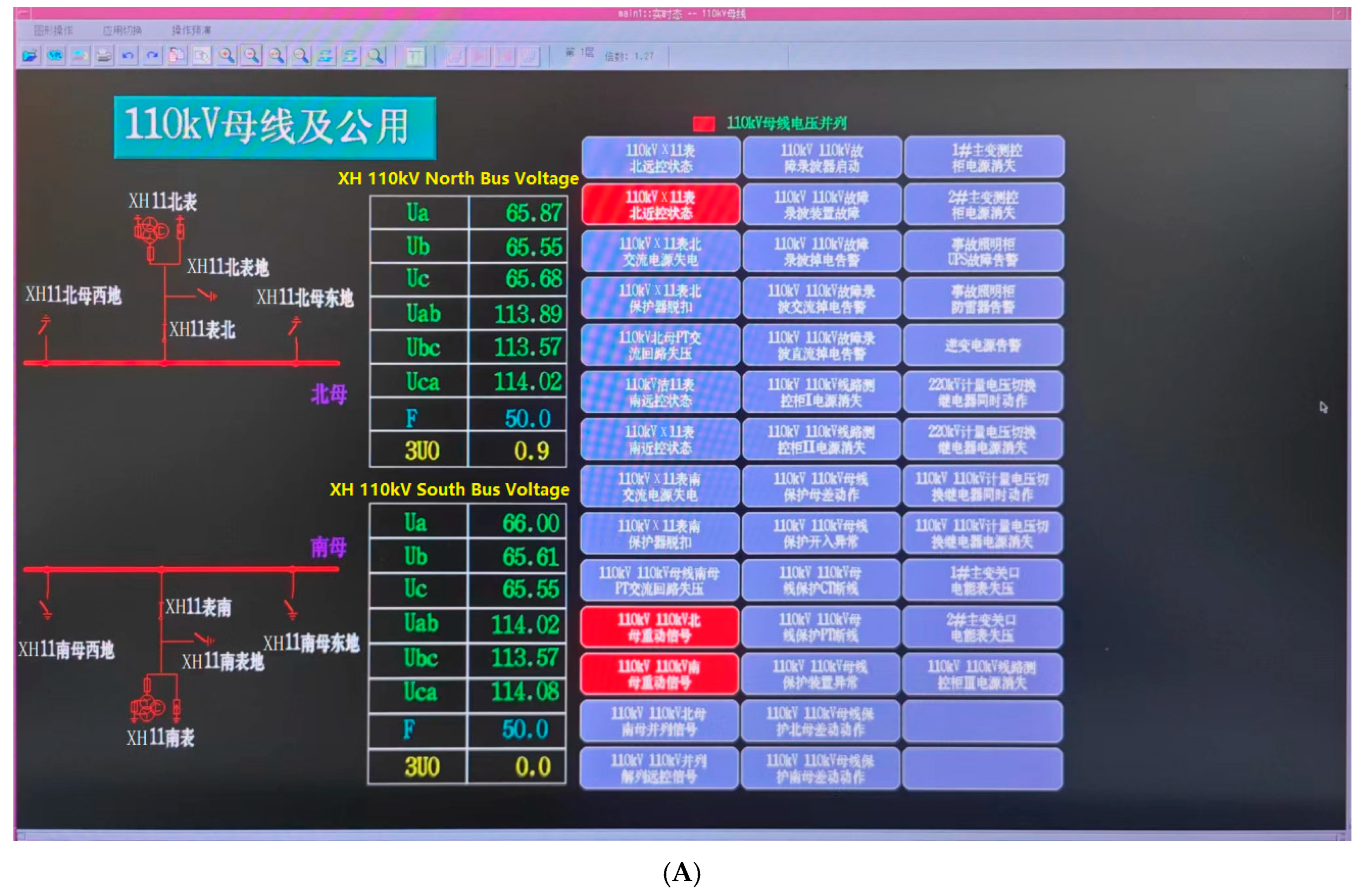
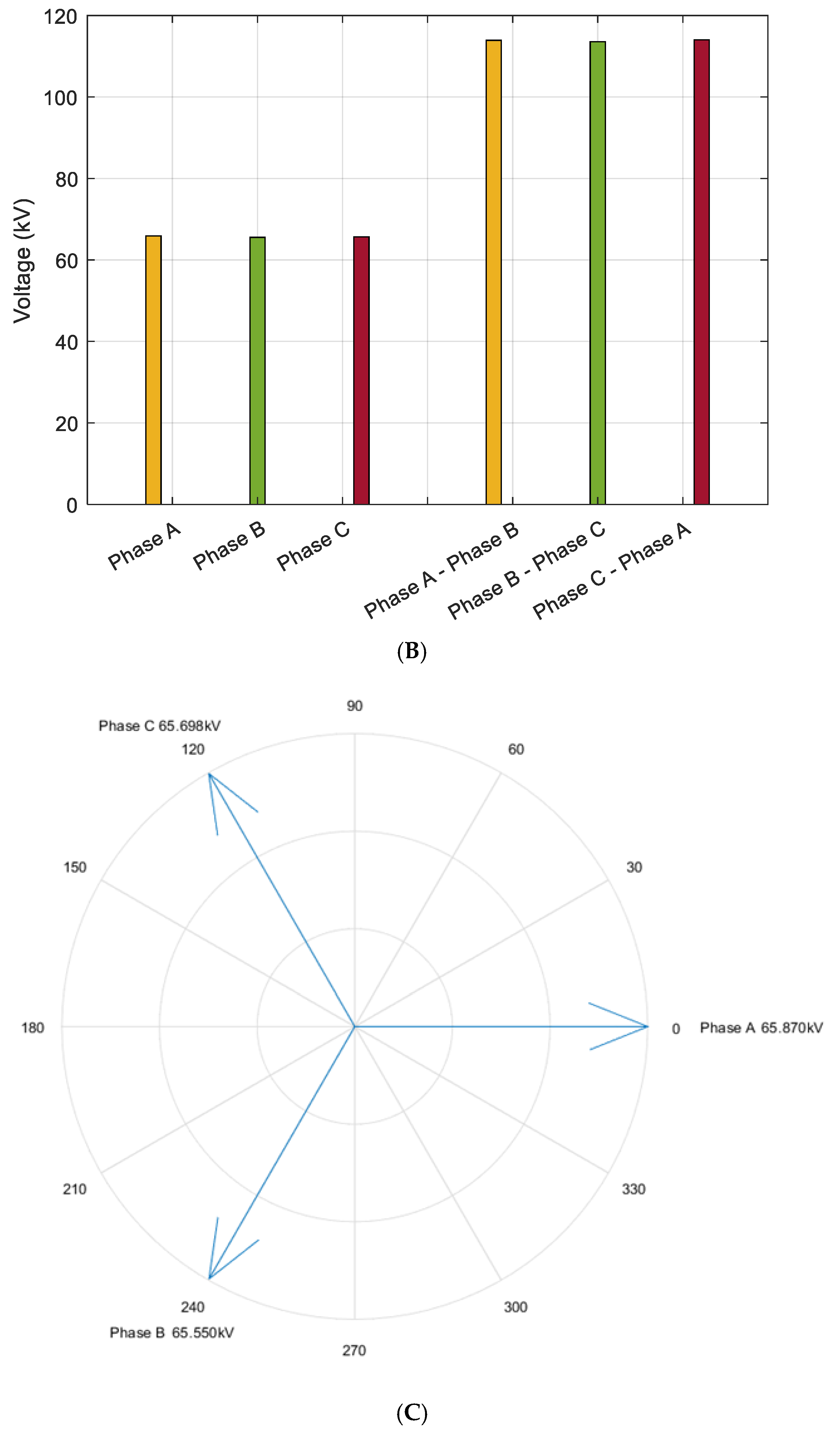
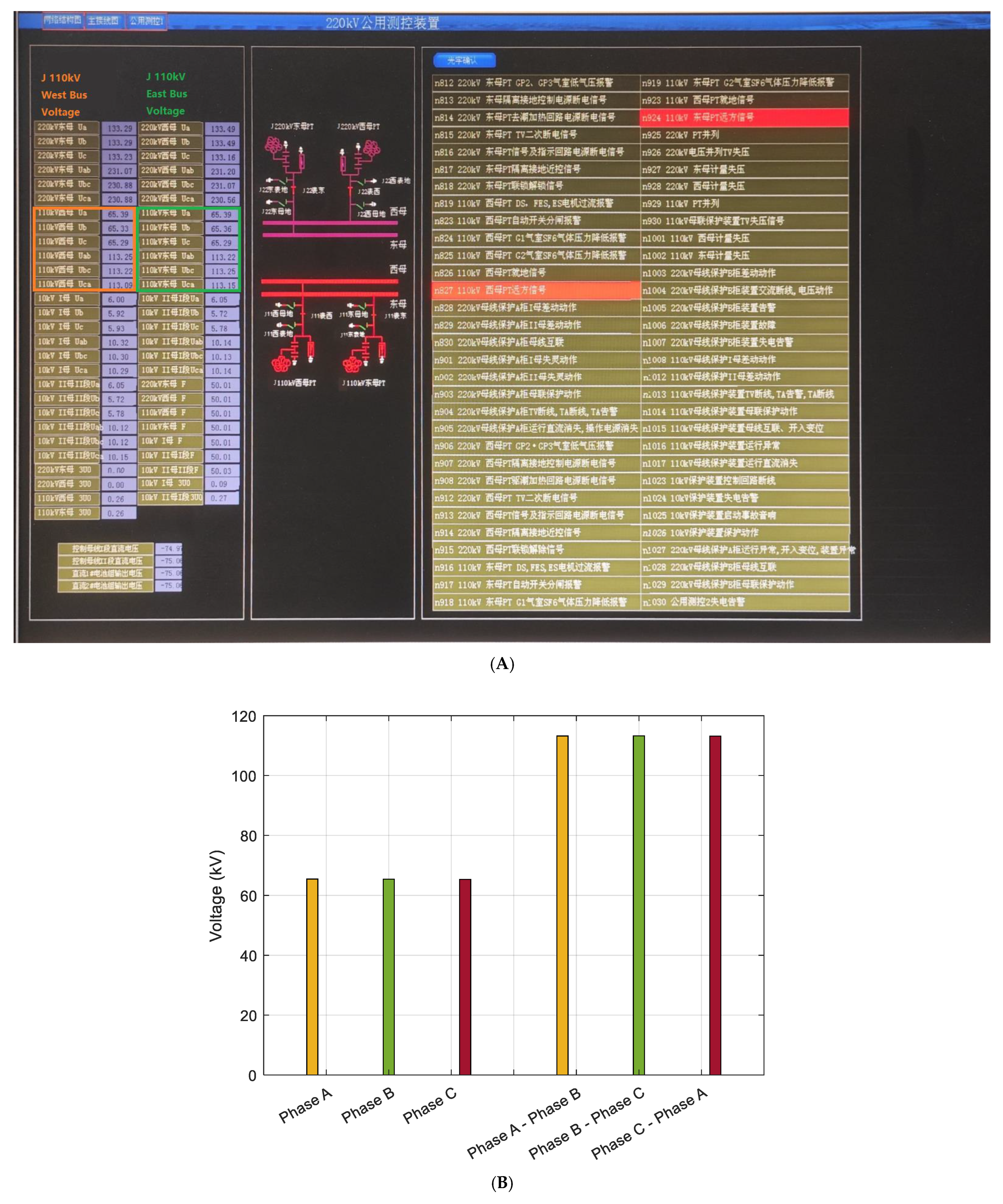
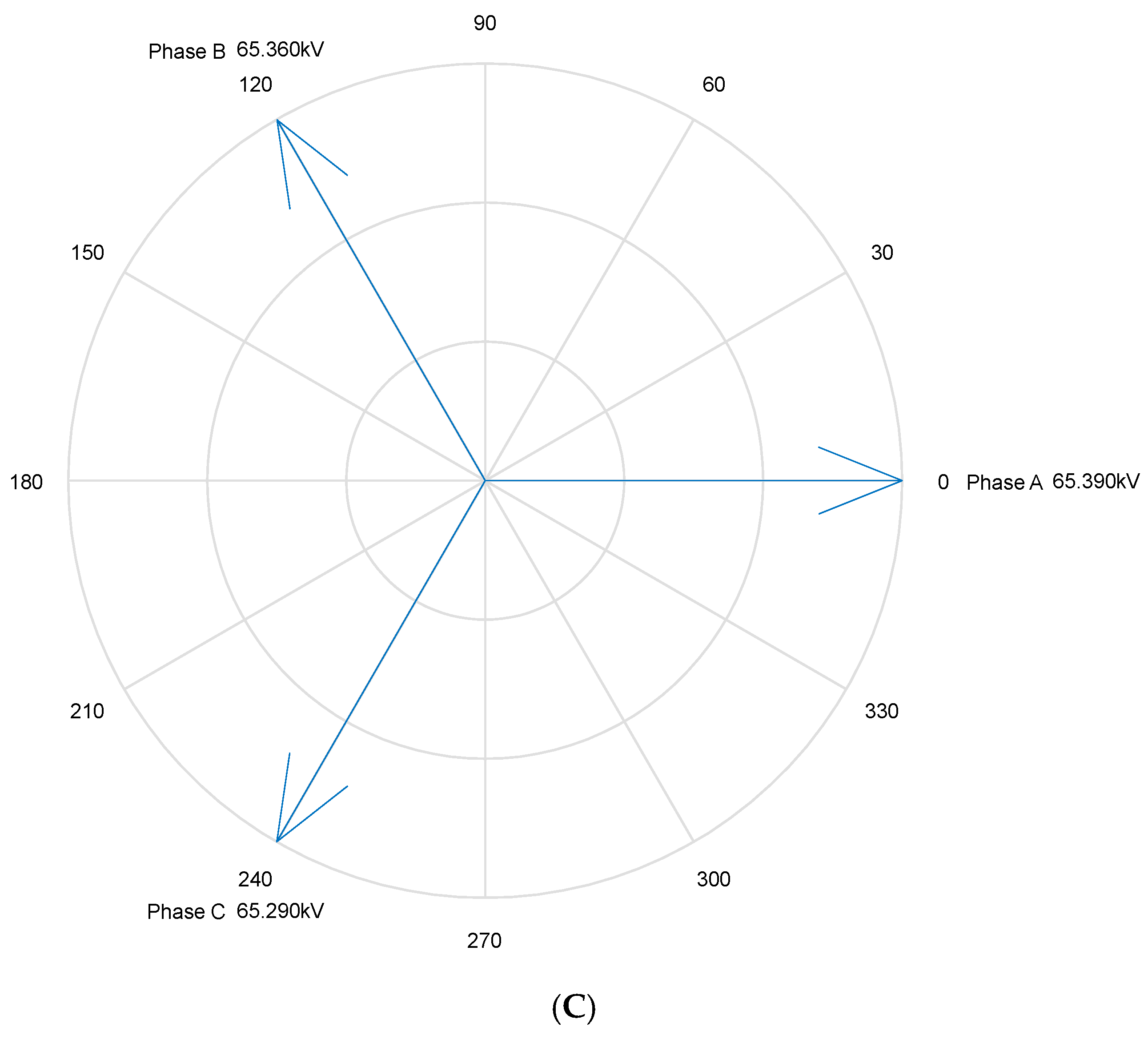
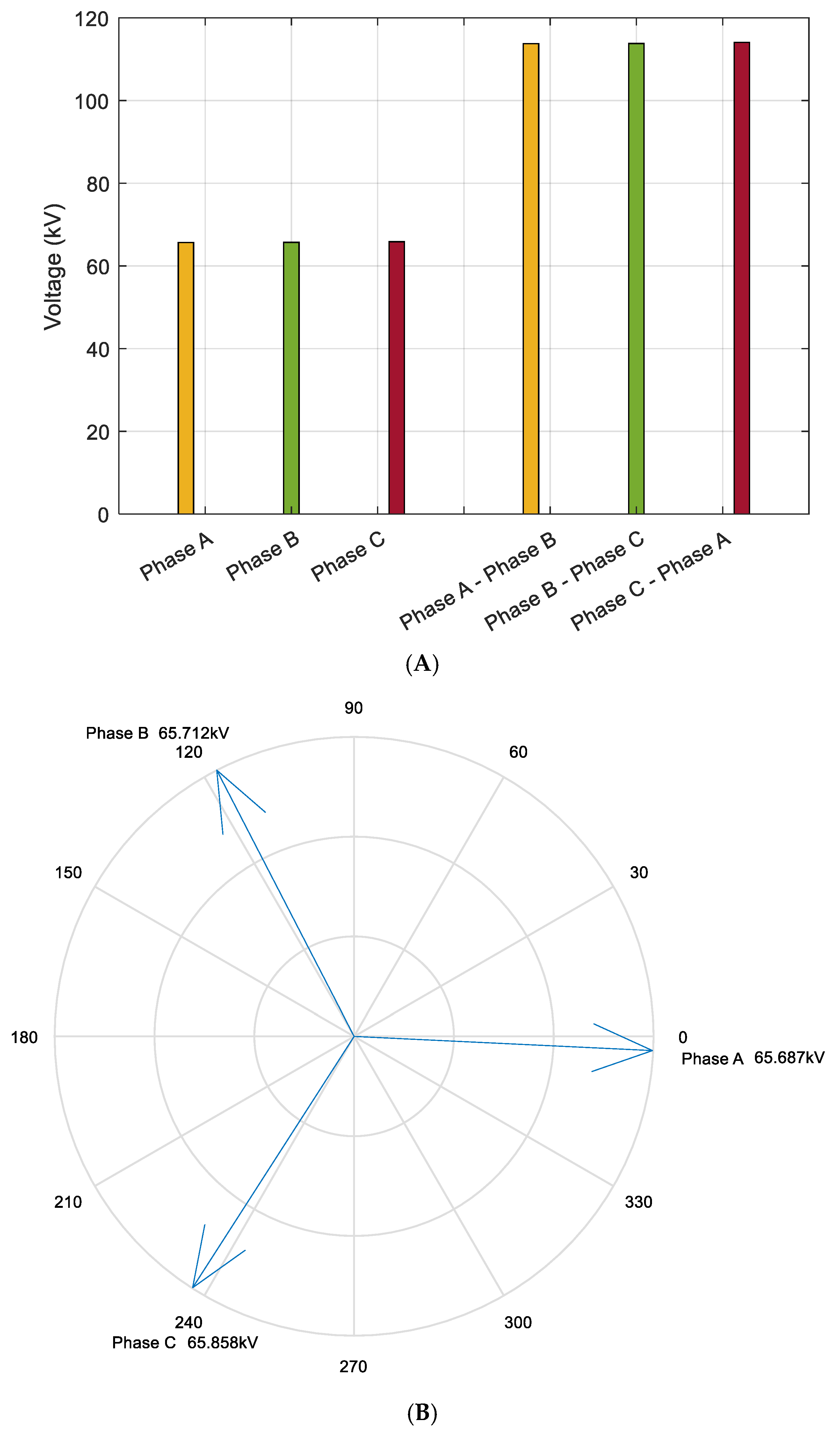
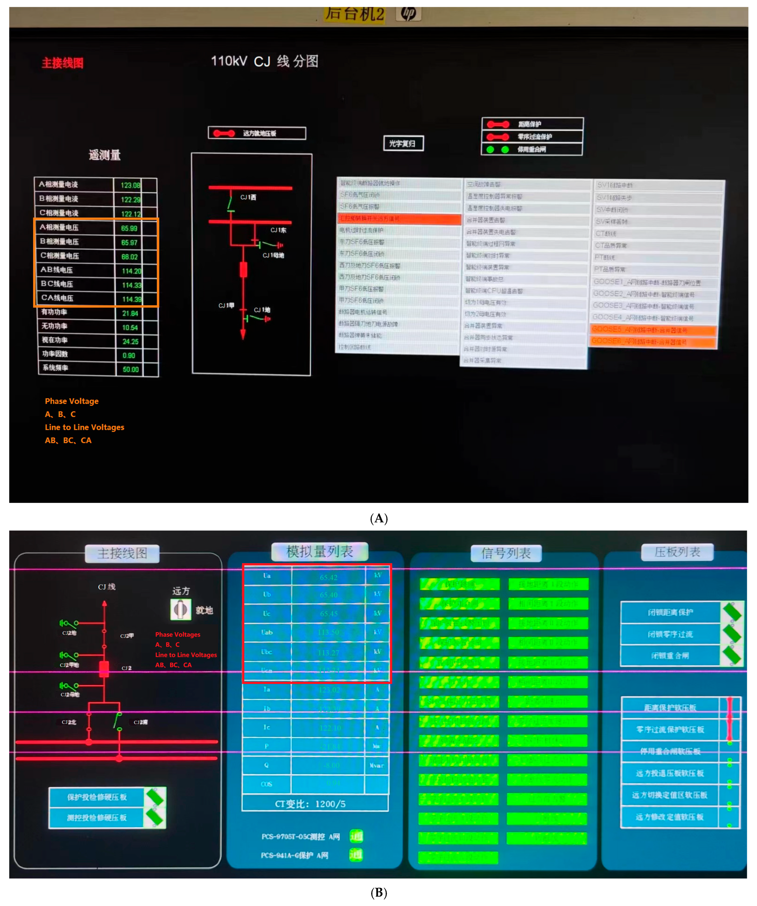
To validate the effectiveness and practical significance of the proposed method and model, a detailed comparative analysis was performed using actual voltage and power measurements from both ends of the existing transmission lines. Specifically, the three-phase voltage of the 110 kV CJ line was directly measured at the power source terminal, while the load-side data were collected from the 110 kV JC (Airport) Substation (
Figure 12). The comparison between measured and calculated values revealed a maximum phase voltage deviation of approximately 10 V and a maximum line voltage deviation within 20 V. Considering the nominal voltage level of 110 kV, which corresponds to a phase voltage around 64 kV (
kV), these deviations are extremely small—on the order of 0.015% to 0.03%. Such minimal error margins, derived directly from raw line data without simplifications, demonstrate that the proposed modeling and calculation approach achieves exceptionally high accuracy and can be regarded as highly reliable for practical engineering applications (
Table 6 and
Table 7).
3.8. Computing Time and Convergence Analysis
To verify the effectiveness of the proposed optimization model and its newly introduced constraints, it was confirmed that all sub-objective functions remain convex across the full range of control variables. Although the addition of constraints and variables increases the problem’s dimensionality, the model exhibits strong robustness and reliable convergence characteristics. The inclusion of additional variables leads to only a minor reduction in iteration speed, with the optimal solution obtained in just 9.45 s. This computation was performed on a standard laptop equipped with an Intel Core i7 2.5 GHz processor (Intel, Santa Clara, CA, USA), without the need for any specialized hardware or high-performance computing resources. In contrast, achieving comparable solution accuracy and speed using bio-inspired algorithms such as Genetic Algorithms (GAs) or Particle Swarm Optimization (PSO) typically requires server-grade computational platforms due to their higher iteration count, stochastic search behavior, and sensitivity to parameter tuning.
Therefore, the proposed method offers significant advantages in computational efficiency and hardware independence. It is highly practical for real-time power system optimization tasks, where fast, accurate solutions are essential for improving system reliability, reducing energy losses, and supporting dynamic decision making under operational constraints.
4. Conclusions
This study presents a practical method for addressing energy loss and voltage drop in long-distance transmission lines by incorporating voltage regulation strategies, originally applied in distribution systems, into transmission line design. The approach effectively enhances voltage quality, improves supply reliability, and reduces overall construction costs. Case studies, including actual high-load scenarios during the summer of 2024, demonstrate that the method can significantly reduce transmission losses and maintain voltage levels within acceptable limits. It also minimizes the need for additional infrastructure, offering clear technical and economic benefits. The method is well suited for engineering applications in industrial power systems, particularly in scenarios requiring high reliability and cost control. Its compatibility with existing assets, combined with low computational demands, supports efficient deployment and operation. These advantages make it a valuable option for strengthening grid performance and ensuring stable, high-quality power supply in industrial and large-scale utility environments.
