Article

Parameter Tuning of Barrier Lyapunov Function-Based Controllers in Electric Drive Systems

by
Marcin Jastrzębski
* and
Jacek Kabziński
Institute of Automatic Control, Lodz University of Technology, Stefanowskiego 18, 90-537 Lodz, Poland
*
Author to whom correspondence should be addressed.
Energies 2025, 18(16), 4301; https://doi.org/10.3390/en18164301
Submission received: 10 July 2025 / Revised: 5 August 2025 / Accepted: 7 August 2025 / Published: 12 August 2025
(This article belongs to the Section F: Electrical Engineering)

Abstract

This paper refers to fast and accurate electric servo control in the presence of position and velocity constraints. This problem, one of the most common nowadays in industrial automation, is often addressed by controllers derived using barrier Lyapunov functions (BLFs). This popular and effective technique is burdened with several difficulties, such as complex feasibility conditions and the inapplicability of the derived controller because of control constraints. In this contribution, we propose a novel, BLF-based, adaptive controller for an electric servo (linear or rotational) with modeling uncertainties, solving a tracking problem. The controller derivation is completed by the tuning procedure, which enables safe system operation in the presence of active control constraints, measurement errors, and noise. The selection of the best combination of BLFs is a part of this procedure. Also, all feasibility issues are solved by the proposed approach. The derivation is completed by extensive numerical simulations and real-life implementation using two different servo systems—the first with a linear permanent magnet motor and the second with a rotational PMSM.

1. Introduction

Over the past decades, electric servo drives have become one of the most popular devices. They are widely used in robotics [1], space technologies [2], machine processing automation, and production process automation [3]. They can be found in all branches of the manufacturing industry, working in cutting [4], welding [5], packaging, renewable energy [6], and many, many other machines [7]. Electric servo drives are found in numerous common devices, from home appliances to building automation devices to applications in diagnostic and medical equipment [8]. They are used in all modern means of transport [9], construction machines, and mining industry machines [10]. Aircraft, naval, and military technology are other extensive fields of servo application [11]. Simply put—precise control of the motion of various devices is a common, basic challenge of modern civilization, and this is exactly what servo drives are designed for. Moreover, due to the widespread use of such drives, their quality of operation and energy efficiency have a huge impact on global electricity consumption and the energy balance.
The main aim of an electric servo is to follow the desired trajectory of motion—position and velocity evolving in time. The servo trajectory must converge to the desired trajectory sufficiently fast, and the quasi-steady-state tracking error must be sufficiently small. From the perspective of control theory, these features are assured by the stability of the closed-loop system. An equally important goal is safe operation. It means that the hard constraints imposed on the position and velocity during motion must be observed under all circumstances: during the transient from arbitrary initial conditions, in the steady state, under external disturbances, in the presence of measurement noise and control constraints, and for any specific features of the hardware.
The well-known control technique that unifies stability and safe operation requirements is the design based on barrier Lyapunov functions (BLFs). The concept of barrier functions dates back to the 1940s (see set invariance research, Nagumo’s results [12]), and the name can be connected with barrier functions used in optimization—components added to a cost function to prevent decision variables from entering a forbidden area. The modern concept of BLFs originated in the first decade of the 21st century, when the concepts of the control Lyapunov function (CLF) and the barrier function were connected [13,14]. A BLF is a CLF that grows to infinity when its arguments approach some limits. By ensuring the boundedness of the barrier Lyapunov function in the closed loop, we ensure that those limits are not transgressed. And as a BLF remains a Lyapunov function (positive definite with a negative definite system derivative), it is also used to prove the closed-loop system’s stability. Since then, BLFs have become a common tool used to derive controllers for numerous applications. Just one popular database reports more than 1500 references using the term “BLF” in the past three years. Variants of motion control are widely represented among them.
Most of the early works on BLFs used the logarithmic BLF for control design [14]. Over time, other types of BLFs were introduced, such as the square of a tangent [15], the tangent of a squared variable [16], or an inverse hyperbolic tangent [17]. Currently, several types of BLFs are in use. Although some comparisons are available [16], the problem of systematically selecting a specific BLF for a particular application remains worth investigating. A recent literature review indicates that the BLF approach continues to be popular. Several new applications are listed in Table 1. In addition to the application area, the table provides information on the type of BLF used, whether the control signal and measurement noise constraints are taken into account, and whether the implementation in a real system is described.
None of the mentioned works justified the choice of a specific BLF, nor did they consider control algorithms using different BLF types in subsystems. Therefore, the shape of the BLF was assumed a priori, without justification, and the same type of BLF was used in all control loops.
Although the BLF-based approach is so popular, it is also known to have several structural drawbacks:
  • As the constraints are imposed on the error system rather than on the original state variables, and the controller is designed recursively so that the acceptable constraint range in the actual loop depends on the controller parameters selected for the previous loop, complex feasibility conditions arise and must be solved or removed [27,28].
  • As the value of a BLF increases rapidly when the barrier is approached and is transformed into the control input, the control amplitude grows rapidly, and a BLF-based controller may become inapplicable because of control constraints.
  • Standard stability proofs and controller derivations do not take into account control constraints and measurement inaccuracies.
Especially, references concerning BLFs together with input constraints are scarce, although the problem is recognized [25,29]. Some approaches assume the transformation of the control input into an additional state variable [30], while others combine BLFs with neural modeling and optimal control [25]. However, it is mostly assumed that control constraints can be practically inactive due to parameter selection.
In this contribution, we propose a novel BLF-based adaptive controller for an electric servo (either linear or rotational) with modeling uncertainties, addressing a tracking problem. The novelty of the proposed controller lies in the fact that it is designed for implementation in the presence of control saturation, measurement noise, and errors. Therefore, the proposed algorithm is equipped with additional parameters that shape the control action and enable the calculation of threshold values of tracking errors that trigger maximum control efforts. The controller derivation is complemented by a tuning procedure that ensures safe system operation under active control constraints, measurement errors, and noise.
Unlike in most references, the maximum values of the saturated control input are effectively used to ‘push’ the tracking error away from the barrier. It is also emphasized that the choice of BLFs (from among several popular types described in the literature) is important for system operation under control constraints. It is demonstrated that using the same type of BLFs for both position and velocity constraints—a typical assumption in previous studies—is not an optimal choice. Selecting the best combination of BLFs is part of the proposed tuning procedure.
Furthermore, all feasibility issues—stemming from the dependence of the achievable limits of the speed tracking error on position constraints and the parameters of the position control loop—are addressed by the proposed approach. The structure of the BLF-based controller with nested loops is preserved, while the feasibility conditions are handled through the tuning procedure. This is in contrast to more complex approaches, where feasibility is ensured via nonlinear state transformations [27,28].
Most references merely acknowledge the existence of feasibility conditions constraining the general algorithm, leaving their resolution to specific applications. Finally, the proposed approach is successfully implemented as DSP-based control of two real servo systems, which proves its practical applicability despite the simplified servo model used in the control design.
We concentrate on time-independent, popular BLFs. We are aware that several other concepts of BLFs can be used. For example, time-varying BLFs were successfully applied to motion control in [31,32], integral BLFs [33], asymmetric BLFs [34], and zone BLFs [35] are promising. However, these approaches are much more complex, while the aim of this paper is to develop a simple but efficient approach, which can be an attractive alternative and widely used in practical applications.
In Section 2, basic facts about BLFs are recollected. The servo model, control objectives, and the derivation of the controller are presented in Section 3. Section 4 is devoted to the tuning procedure, ensuring safe operation. In Section 5, examples, simulations, and real servo implementations are reported. Finally, conclusions are presented in Section 6.

2. Barrier Lyapunov Functions

The concept of barrier Lyapunov functions (BLFs) was introduced 20 years ago, first regarding systems in Brunovsky canonical form [13]. In [14] basic definitions and properties of BLFs were derived. For the sake of completeness, we repeat them here.
Definition 1.
Let V : R n R  be a continuously differentiable, proper, and positive definite function defined over the state-space of the nonlinear system x ˙ = f ( x , u ) . Let us denote the Lyapunov function system derivative by V ˙ ( x , u ) = V x T f ( x , u ) . V(x) is called a control Lyapunov function (CLF) for the system x ˙ = f ( x , u )  if, for any x 0 , there exists such u that V ˙ x , u < 0 . If V x = x T P x  for some positive definite P, it is called a quadratic Lyapunov function (QLF).
Definition 2.
A barrier Lyapunov function (BLF) is a scalar function V ( x ) , described by the following:
  • It is defined on an open region D containing the origin of the state-space of the system x ˙ = f ( x ) .
  • It is continuous, positive definite.
  • It possesses continuous first-order partial derivatives at every point of D,
  • V ( x )  as x approaches the boundary of D,
  • M ,   t > 0   V x t < M  along any system trajectory starting inside D.
Usually, it is assumed that D is a hyper-rectangle defined by D = x : x i Δ x i .
Lemma 1.
([14]). Consider a smooth dynamical system z ˙ = f ( t , x , w ) , with the state variables z = x , w T . Let V i ( x i )  be a BLF satisfying V i x i   i f   x i ± Δ x i . Let Q ( w )  be a QLF. Let V = i = 1 d i m ( x ) V i x i + Q ( w ) . If the inequality V ˙ = V T z f 0  holds throughout the set S = x , w : x i < Δ x i , then any system trajectory that fulfils the initial constraints i   x i 0 < Δ x i  remains within S  for any t 0 .
In Lemma 1, the state is split into the constrained variables x and the unconstrained variables w. For each x i , a BLF is constructed, while a QLF may be used for w . For tracking problems, the state variables considered are the tracking errors, and, in the case of motion control, these are position- and velocity-tracking errors. BLFs are separately designed for each of these errors.
Let us consider a scalar tracking error e i and a corresponding BLF V i ( e i ) .
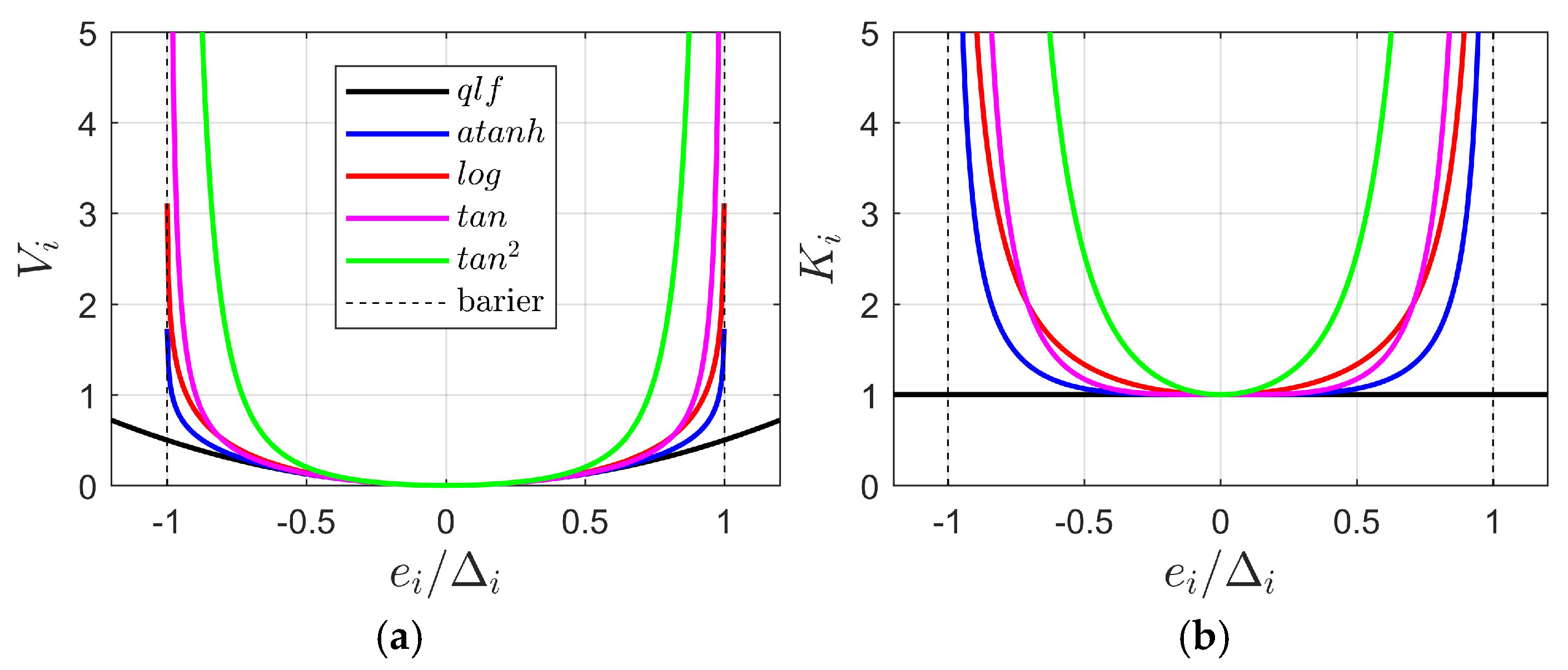
We can choose among several types of BLFs. It is well known that the features of the obtained closed-loop system strongly depend on the selected BLF type. The main differences among them lie in their behavior near the constraint boundary—some grow faster, others slower. It is strictly connected with the values of BLF’s derivative d V i d e i , which can be represented as d V i d e i = K i ( e i )   e i . Moreover, as it will become clear from the derivation presented in the next section, K i ( e i ) acts as a gain transmitting the tracking error into the control law and the adaptive laws. The formulas describing a QLF and four selected BLFs according to this notation are presented in Table 2, and the plots of V i e i and K i ( e i ) are presented in Figure 1, assuming that the constraint e i i holds.
The contents of Table 2 do not exhaust all possible forms of BLF construction. In fact, any smooth function that approaches zero as the variable nears the barrier can be inverted to obtain a BLF. For example, the function cos π 2 e i Δ i provides a secant-type BLF [36]. Recently, the most frequently used BLFs have been logarithmic functions [18,19], and control algorithms based on them have been most commonly implemented in real systems [20,21]. Papers describing controllers that use BLFs with a squared variable [22] are less common. No publications employing BLFs based on the inverse hyperbolic tangent or the squared tangent were found among last year’s papers.
The set of functions presented in Table 2 includes both the most popular and less frequently used types. The criterion for their selection was to present the greatest possible variety in terms of functional shape. Naturally, this set can be expanded to include other Lyapunov-based functions.
Considering practical implementation of the BLF-based controller, we have to take into account that the measured value e i can incidentally go outside the constraint (for example, as a result of a single measurement outlier). The l o g -BLF is undefined in this situation, tan-BLF changes the sign, and atanh-BLF and tan2-BLF are symmetric with respect to the barrier, but the gains they generate are changing the sign. All this can be catastrophic for the proper system operation and should be avoided.
To summarize:
  • The choice of used BLFs is an important decision and should be considered carefully.
  • The shape of a BLF and of the gain it introduces is crucial for real system implementation, especially in the presence of control constraints and measurement noise, and hence, the BLF should be equipped with additional parameters able to change it near the barrier for safe operation.
In the Section 3, an adaptive motion controller corresponding to these postulates will be derived.

3. BLF-Based Motion Adaptive Controller

Let us consider a universal, nonlinear model of an electric servo given by two differential equations:
x ˙ 1 = x 2 I x ˙ 2 = k u u F x 1 , x 2 u = s a t ± u M u d .
The same Equations (1) are used to model both a servo generating linear motion and a rotational servo. While we acknowledge that this is a simplified, second-order model, we are confident—based on real servo applications reported in Section 5—that this modeling approach is sufficiently accurate and well justified. It captures the main sources of control difficulty, such as nonlinear external forces or torques, including friction or nonlinear loads.
The proposed approach accounts for modeling uncertainties related to parameter inaccuracies as well as unstructured modeling errors and external disturbances. In modern electric servo drives, current regulation is performed by a fast controller integrated with a PWM converter. The switching frequencies of modern power electronic converters are much higher than the sampling rates used in speed and position control loops. As a result, the time constant of the current response is significantly shorter than the time constants associated with mechanical transients (see Section 5).
Numerous experiments and real-world servo applications, as reported in Section 5, demonstrate that the derived controller is typically robust to unmodeled current-loop dynamics. More critical factors affecting system performance include current constraints and the imprecisely known torque (or force)-to-current constant k u , both of which are taken into account in the proposed model. Thus, the current control loop dynamics are neglected, and the desired motor current u d is treated as the servo control input.
The state and control variables, as well as model parameters, are summarized in Table 3.
The term k u u represents the propelling force or torque. The constant k u > 0 is usually provided by the motor manufacturer, but, in some applications, it may be inaccurate or vary with external conditions, such as the motor temperature, etc. If k u is known exactly, assume that k u = 1 does not limit the generality of the analysis. However, if this constant is unknown, a slightly modified version of Equation (1) should be considered.
For the formal derivation of the controller, we also assume that the saturation affecting the motor current is inactive, although it must be taken into account at the implementation stage.
Finally, the simplified servo model is formalized as follows:
x ˙ 1 = x 2 I u x ˙ 2 = u F u x 1 , x 2   I u = I k u > 0 ,         F u x 1 , x 2 = F x 1 , x 2 k u   .
and the motor current is the control input.
The component F x 1 , x 2 is intended to model all other forces/torques affecting the motion. It includes the impact of motor and load friction, as well as any external forces acting on the system. For instance, if the servo works against gravity while lifting or lowering a load, or against elastic forces when stretching or compressing a spring, these forces or torques should be included in the component F x 1 , x 2 . The decision of which forces or torques to include in this model is application-specific and depends on the actual system. Sometimes, the function F x 1 , x 2 can be naturally interpreted as a linear combination of known functions (see examples in Section 5). More often, this component is unknown, but it can be represented by data obtained from some identification experiments [37] and then approximated by a linear combination of known functions. This form can also be interpreted as the result of fuzzy modeling or modeling by artificial neural networks [38]. However, it is assumed that F u x 1 , x 2 can be modeled by a linear-in-parameters model g T ψ x 1 , x 2 :
F u x 1 , x 2 = g T ψ x 1 , x 2 + ε .
The vector ψ x 1 , x 2 consists of known functions of motor position and velocity, while the parameters g are constant and unknown. The actual number and form of the known functions ψ x 1 , x 2 should be determined for each application. However, it is assumed that such a model with constant, bounded, unknown parameters g exists, and that the modeling error ε is bounded at any moment during system operation:
ε ( t ) ε m < .
The motor and load inertia I (and therefore also I u ) is constant, but unknown. The constraints ± u M imposed on the motor current are known an inviolable.
The control aim is to follow a smooth, constrained, desired position trajectory
x 1 d x 1 m < ,          x ˙ 1 d x 2 m <
and it is required that the tracking error:
e 1 = x 1 d x 1
remains constrained within the imposed bounds Δ 1 :
| e 1 ( t ) | < Δ 1 .
As an intermediate stage of the controller design, the desired velocity trajectory x 2 d will be proposed:
x 2 d = x ˙ 1 d + k 1 e 1 ,
where k 1 > 0 is a design parameter. Hence, if a steady state e 1 0 is achieved, then x 2 d x ˙ 1 d . The velocity tracking error is defined as follows:
e 2 = x 2 d x 2 .
A constraint is imposed on the velocity tracking error is as follows:
| e 2 ( t ) | < Δ 2 .
Therefore, taking into account the constrained desired trajectory (5), the selected parameter k 1 , and the error constraints (7) and (10), the state variables are also bounded:
x 1 d Δ 1 x 1 x 1 d + Δ 1 , x 2 d Δ 2 x 2 x 2 d + Δ 2 | x 1 ( t ) | < Δ x 1 , | x 2 ( t ) | < Δ x 2 .
The constraints in (11) depend on the selected desired trajectory x 1 d (and x ˙ 1 d ), design parameter k 1 , and the imposed error constraints (7) and (10). The proper selection of these design components to match predefined global constraints (11), considering the servo dynamics (2), creates the feasibility problem, which must be addressed in any BLF-based design.
Because of (2), (3), (6), (8), and (9), the tracking errors are described by the following:
e ˙ 1 = x ˙ 1 d x 2 = k 1 e 1 + e 2 ,
I u e ˙ 2 = I u x ˙ 2 d I u x ˙ 2 = I u x ˙ 2 d u + F u x 1 , x 2 = I u x ˙ 2 d u + g T ψ x 1 , x 2 + ε = f T φ x 1 , x 2 u + ε ,
where
f T = I u g T = f 1 f p ,    φ x 1 , x 2 = x ˙ 2 d ψ x 1 , x 2 .
Note that x ˙ 2 d = x ¨ 1 d + k 1 e ˙ 1 = x ¨ 1 d + k 1 ( k 1 e 1 + e 2 ) is available for the controller.
The unknown parameters f will be replaced by adaptive parameters f ^ , which will be updated using an adaptive law to be derived. The adaptation error is denoted by the following:
f ~ = f f ^ .
The controller derivation is based on proper shaping of error dynamics. Constraints (7) and (10) will be assured by two BLFs V 1 ( e 1 ) and V 2 ( e 2 ) . Let us denote the following:
1 e i δ V i δ e i = K i e i > 0 .
Let us consider Lyapunov function:
V e 1 , e 2 , f ~ = κ 1 V 1 e 1 + I u V 2 e 2 + 1 2 f ~ T Γ 1 f ~ .
where κ 1 > 0 and positive definite Γ are design parameters. The derivative of the Lyapunov function is given by the following:
V ˙ e 1 , e 2 , f ~ = κ 1 K 1 e 1 e 1 e ˙ 1 + K 2 e 2 e 2 I u e ˙ 2 + f ~ T Γ 1 d d t f ~ .
We now propose the following control law:
u = f ^ T φ x 1 , x 2 + κ 1 K 1 e 1 K 2 ( e 2 ) e 1 + κ 2 ( e 2 ) e 2 + 1 2 σ K 2 e 2 e 2 ,
where κ 1 > 0 ,   σ > 0 are design parameters, and the strictly positive function κ 2 e 2 > 0 will be discussed in the next section. Roughly speaking:
  • κ 2 e 2 = k 2 > 0 when e 2 is far from the constraint | e 2 ( t ) | < Δ 2 to ensure sufficiently fast convergence of e 2 ;
  • κ 2 e 2   κ 2 H when e 2 approaches the constraint to mobilize using maximum control value to avoid getting to close to the barrier.
Therefore, the error dynamics for e 2 , as derived from Equation (13) and control law (19), become the following:
I u e ˙ 2 = f T φ x 1 , x 2 u + ε = f ~ T φ x 1 , x 2 κ 1 K 1 e 1 K 2 e 2 e 1 κ 2 e 2 e 2 1 2 σ K 2 e 2 e 2 + ε .
Now, substituting Equations (12) and (20) into the Lyapunov function derivative (18), taking into account that: d d t f ~ = d d t f ^ , and noticing the following:
κ 1 K 1 e 1 e 1 e 2 K 2 e 2 e 2 κ 1 K 1 e 1 K 2 e 2 e 1 = 0 , K 2 e 2 e 2 ε 1 2 σ K 2 2 e 2 e 2 2 1 2 σ ε 2 1 2 σ ε m 2
we obtain the following:
V ˙ = κ 1 K 1 e 1 e 1 k 1 e 1 + e 2 + K 2 e 2 e 2 f ~ T φ x 1 , x 2 κ 1 K 1 e 1 K 2 e 2 e 1 κ 2 e 2 e 2 1 2 σ K 2 e 2 e 2 + ε + f ~ T Γ 1 d d t f ~ = k 1 κ 1 K 1 e 1 e 1 2 + f ~ T K 2 e 2 e 2 φ x 1 , x 2 Γ 1 d d t f ^ κ 2 e 2 K 2 e 2 e 2 2 1 2 σ K 2 2 e 2 e 2 2 + K 2 e 2 e 2 ε k 1 κ 1 K 1 e 1 e 1 2 κ 2 e 2 K 2 e 2 e 2 2 + f ~ T K 2 e 2 e 2 φ x 1 , x 2 Γ 1 d d t f ^ + 1 2 σ ε m 2
This equation can now be simplified and rearranged to design an adaptive update law. Let us select adaptive laws with projection:
d d t f ^ = P r o j f m , f M y , f ^ , y = Γ K 2 e 2 e 2 φ x 1 , x 2
where the projection operator is defined by the following:
P r o j f m , f M y , f ^ = p r o j f m , 1 , f M , 1 ( y 1 , f ^ 1 ) p r o j f m , p , f M , p ( y p , f ^ p ) T ,
p r o j f m , i , f M , i ( y i , f ^ i ) = 0   i f   f ^ i f m , i   a n d   y i < 0 0   i f   f ^ i f M , i   a n d   y i > 0 y i   i n   a n y   o t h e r   c a s e         ,
It is well known [39] that for any trajectory f ^ evolving according to differential equation d d t f ^ = P r o j f m , f M y , f ^ and starting within f m < f ^ < f M (elementwise), these bounds are preserved for any t , and the inequality:
f f ^ T y P r o j f m , f M y , f ^ 0
holds for any t as well.
Therefore, under adaptive law (23), the inequality (22) becomes the following:
V ˙ k 1 κ 1 K 1 e 1 e 1 2 κ 2 e 2 K 2 e 2 e 2 2 + 1 2 σ ε m 2
The final controller is summarized in Table 4.
The final closed-loop system is described by Equations (12), (20), and (23). Let us denote the set of state variables e 1 ,   e 2 lying within the constraints:
E = e = e 1 e 2 :    | e 1 | < Δ 1 ,     | e 2 | < Δ 2  
and the compact set C f contains all possible values of the adaptive error f ~ . Such a set exists as the ‘best’ values f in (14) are bounded, and the adaptive parameters are constrained f m < f ^ < f M .
The system (12), (20), and (23) with state variables e 1 ,   e 2 ,   f ~ is said to be uniformly, ultimately bounded (UUB) to the target set B , if there exist a compact set B E × C f , called the target set, and a constant T such that any trajectory starting in E × C f remains in B for all t > T .
The derived inequality (27) forms the basis for proving the closed-loop system stability in this sense. The stability of the closed-loop system is summarized by the following theorem.
Theorem 1.
Consider the closed-loop system Σ  given by Equations (12), (20), and (23). Then, for any trajectory [ e , f ~ ]  such that e ( 0 ) E :
  • The condition e ( t ) E  holds for all t > 0 .
  • The trajectory is UUB to a compact target set B . Each e i  tends to a compact interval containing 0. This interval can be made arbitrarily narrow and the convergence arbitrarily fast, by selecting sufficiently large design parameters.
  • All signals in the system Σ  are bounded.
  • If the linear-in-parameters model (2) is accurate, i.e., ε = 0 ,   ε m = 0 , than we can take σ = 0  to simplify the control law (19). Under this simplified control, statements 1–3 still hold and the tracking error e  converges to zero asymptotically.
The proof of the theorem is based on the following reasoning:
Since K 1 e 1 1 ,   K 2 e 2 1 , κ 2 e 2 k 2 m i n , it follows from the inequality (27) that the Lyapunov function derivative along any trajectory of Σ is negative outside the compact set E 0 = e :   e 2 1 2 σ · min { k 1 κ 1 , k 2 m i n } ε m 2 , for any f ~ . Therefore, the Lyapunov function decreases until the trajectory enters the target set B = E 0 × C f . The set E 0 can be shrunk by increasing σ · min { k 1 κ 1 , k 2 m i n } . As the Lyapunov function V is bounded, the BLFs V 1 and V 2 are also bounded, which guarantees that e ( t ) E .
Let us stress that using BLF results in keeping the tracking errors e = e 1 e 2 within the constraints, while constraining position x 1 and velocity x 2 is a more practical control objective. As for the position, x 1 ( t ) remains within the Δ 1 -tube around x 1 d ( t ) : min t x 1 d t + Δ 1 x 1 t max t x 1 d t + Δ 1 .
To constrain the velocity x 2 ( t ) , let us notice that the desired velocity x 2 d , defined by (8), differs from the tracked trajectory velocity x ˙ 1 d . Let us relate the tracking error bound (10) and the desired velocity x 2 d given by (8) to obtain:
x ˙ 1 d + k 1 e 1 x 2 2
2 k 1 e 1 x ˙ 1 d x 2 2 k 1 e 1 .
Hence, the actual velocity x 2 remains within the 2 -tube around the tracked trajectory velocity x ˙ 1 d only when the position tracking error is zero. In general, we have the following:
x ˙ 1 d x 2 2 + k 1 1 ,
thus:
min t x ˙ 1 d t 12 x 2 t max t x ˙ 1 d t + 12 ,    12 2 + k 1 1 .
Therefore, the gain k 1 , which governs the convergence of the position error, directly enlarges the practical constraints on the velocity.
Let us consider the error dynamics (12) and (20). If we can neglect the adaptation and modeling errors and assume that the tracking errors e 1 and e 2 are small, so K 1 e 1 1 and K 1 e 1 1 , κ 2 e 2 = k 2 , the simplified error dynamics is given by the following:
e ˙ 1 I u e ˙ 2 k 1 1 κ 1 k 2 e 1 e 2 .
The characteristic polynomial of system (33) is as follows:
M s = s 2 + s k 1 + k 2 I u + k 1 k 2 + κ 1 I u .
The imposed eigenvalues of the system (33) can be used to select k 1 ,   k 2 ,   κ 1 .
Let us conclude the presented derivation and discussion with an example illustrating the impact of various BLFs and the problem of constrained control.
Example 1.
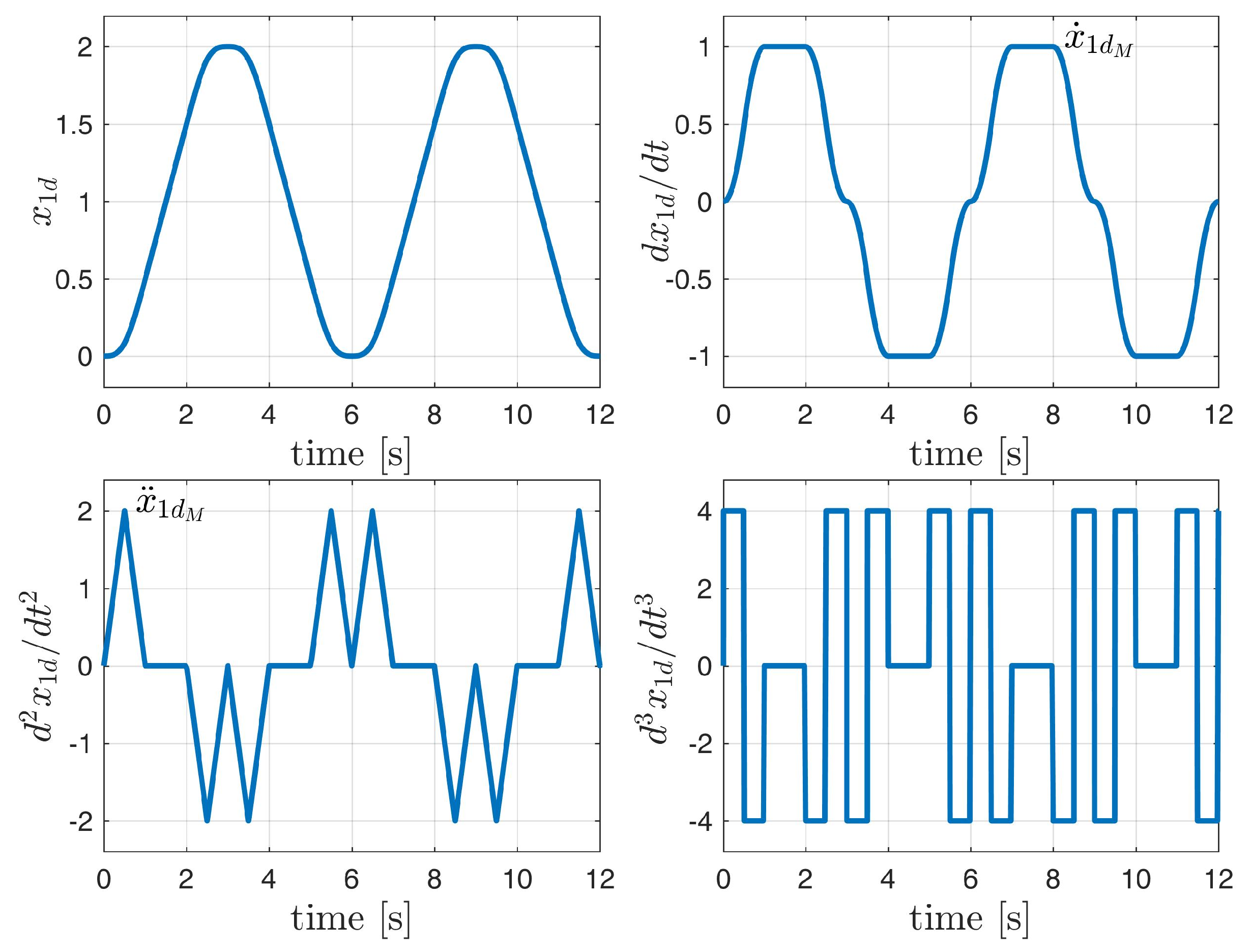
All signals and parameters are presented using SI units, as shown in Table 3. Let us consider the desired trajectory presented in Figure 2. The maximum values of velocity and acceleration are x ˙ 1 d M = 2 ,   x ¨ 1 d M = 10 .  This trajectory was generated starting from x 1 d ( t )  by subsequent integration with zero initial conditions.
The rotational servo is given by Equation (1), where I = 10 ,   k u = 1 . The external forces include friction—proportional to the angular velocity x 2 , and a gravitational component, which varies during each full rotation and is proportional to sin x 1 . Hence, g T = [ 3 ,   5 ] , ψ x 1 , x 2 = [ sin x 1 , x 2 ] , and no modeling error is assumed: ε = 0 . Under these assumptions, the error dynamics are given by the following:
e ˙ 1 I u e ˙ 2 k 1 1 κ 1 K 1 e 1 K 2 e 2 k 2 e 1 e 2 .
The constraints imposed on the tracking errors e 1 , e 2 are Δ 1 = 1.1 and Δ 2 = 2.2 . Let us assume the controller gains are k 1 = 1 , k 2 = 0.1 , κ 1 = 1 , κ 2 ( e 2 ) = k 2 . The eigenvalues of the simplified system (33) are 0.8858 and 0.1242 , suggesting an aperiodic transient with a time constant ~ 8 . The velocity bound 12 , according to Equation (32), is 12 = 2.2 + 1 · 1.1 = 3.3 . It is assumed that the parameters are known exactly, so adaptation is switched off, and so f ~ = 0 . The controller is initialized with the following conditions: x 1 0 = 1 ,   x 2 0 = 1 . Given that x 1 d 0 = 0 , x ˙ 1 d 0 = 0 , the initial tracking errors are e 1 0 = 0 1 = 1 , x 2 d 0 = 0 + 1 · 1 = 1 , e 2 0 = 1 1 = 2 . Thus, the initial point lies within the specified constraints.
Let us consider two selections of BLFs:
(A) 
V 1 : t a n 2 -BLF, V 2 : a t a n h -BLF,
(B) 
V 1 : l o g -BLF, V 2 : t a n -BLF.
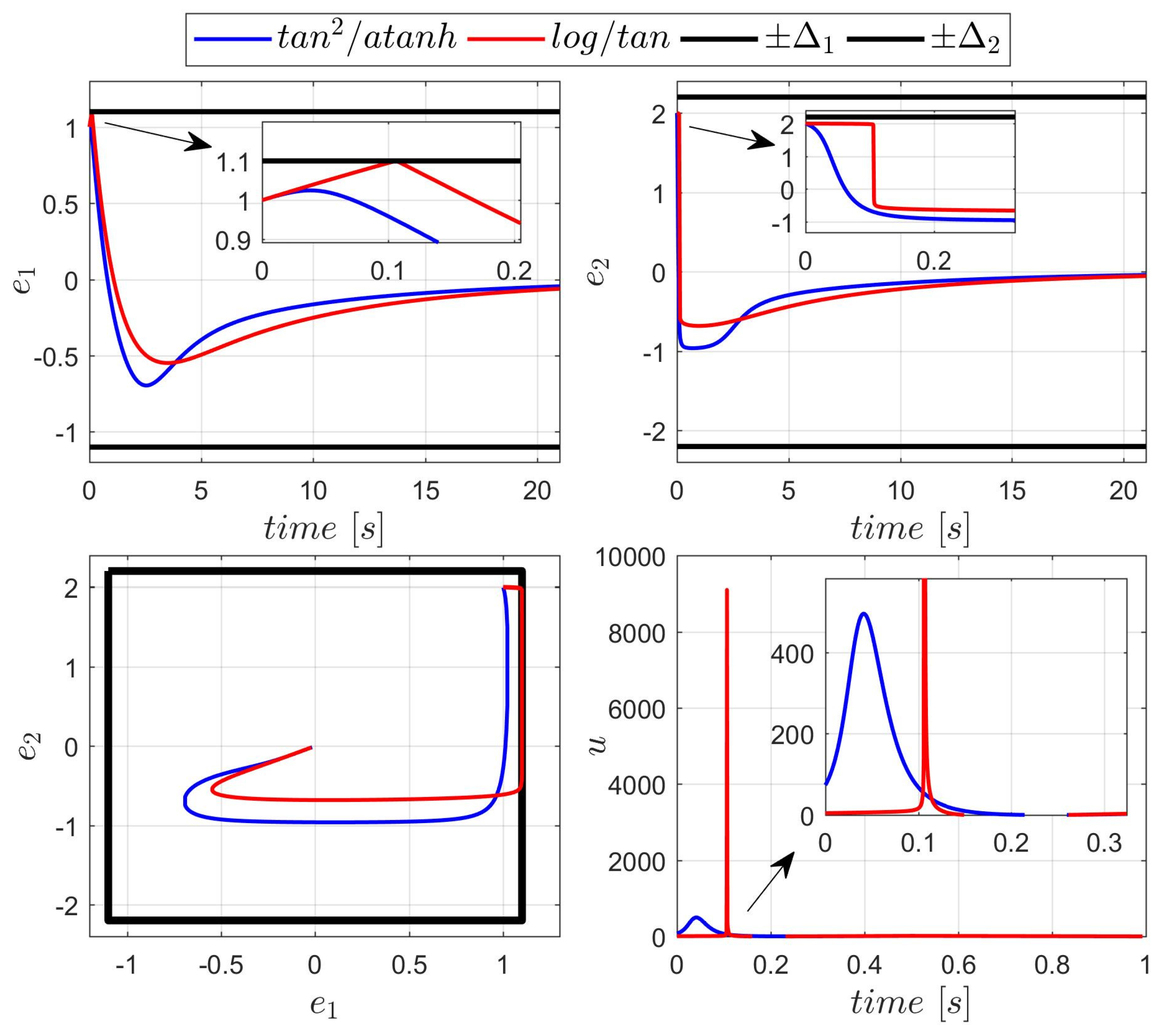
During the first experiment, the control was unconstrained: u M = . The results are presented in Figure 3.
As observed in Figure 3, selection B of BLFs results in much more aggressive control: The trajectories get closer to the constraints, and the control signal reaches unacceptably high values (albeit briefly). The repulsion from the constraint boundary begins later (i.e., closer to the bound), requiring a rapid increase in control effort. However, the settling time and transient shapes are similar for both BLF selections. Quality indices concerning both BLF combinations are presented in Table 5.
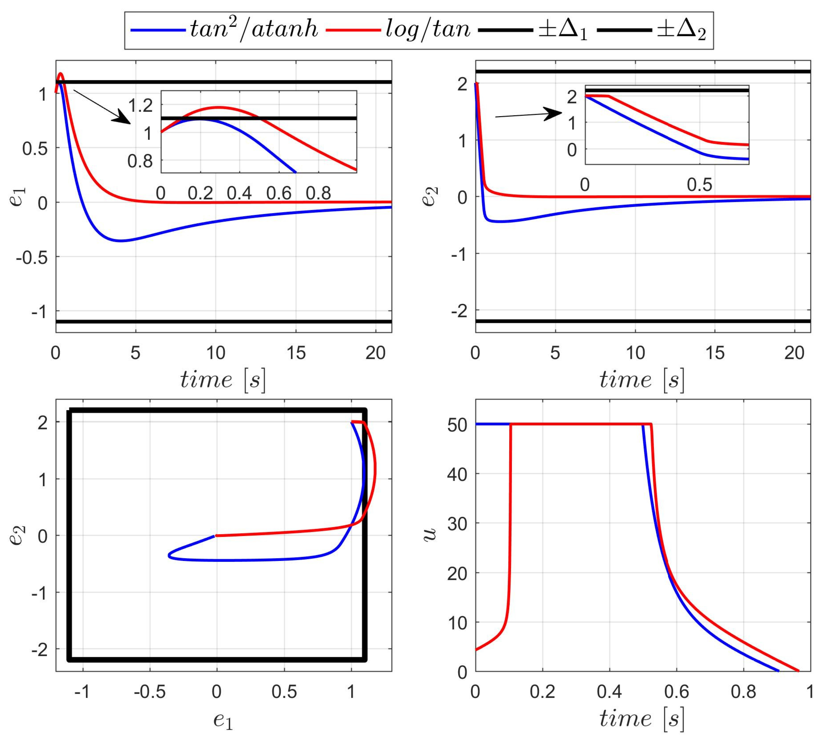
In the second experiment, the control input was constrained: u M = 50 , and the control law was modified as follows:
u = s a t ± u M f T φ x 1 , x 2 + κ 1 K 1 e 1 K 2 ( e 2 ) e 1 + κ 2 ( e 2 ) e 2
This upper limit is significantly lower than the peak control values observed in the previous test. Therefore, it is expected that the position and/or velocity constraints might be violated. Since BLF values are undefined outside the constraint boundaries, a safety mechanism is introduced: If the limit e i i = 0.99 is reached, the value of e 1 is held constant (i.e., blocked) for the controller.
The results are presented in Figure 4. Only the controller with the first (A) selection of BLFs was able to keep the transient within the constraints. This controller reaches the control saturation level earlier, due to the higher value of the gain κ 1 K 1 e 1 K 2 e 2 , and is able to push the position error away from the constraint barrier. The second controller (BLFs B, red line in Figure 4) reaches the maximum control value too late to effectively correct the trajectory.
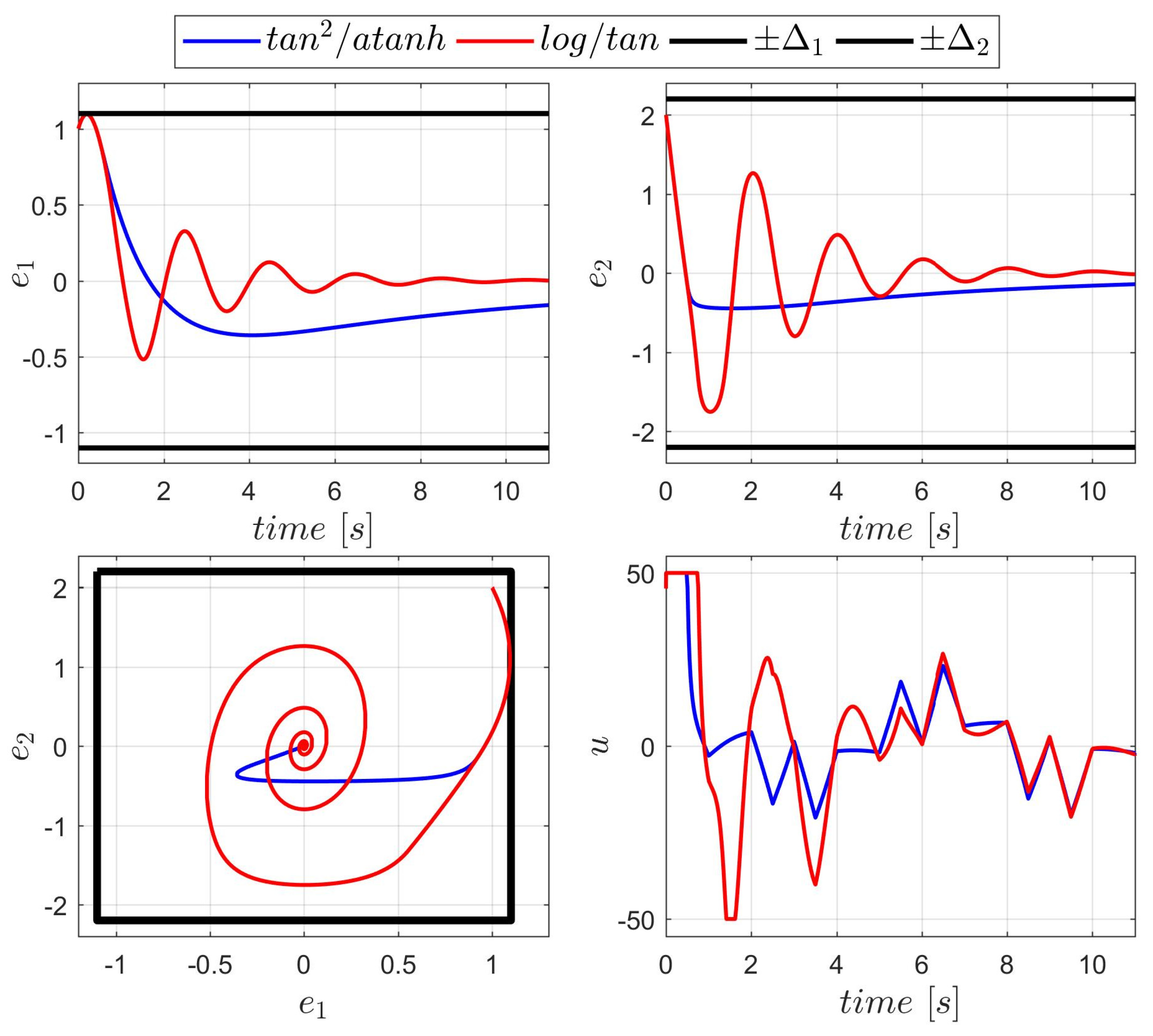
For the final run, the coefficient κ 1 , scaling the BLF V 1 , was increased to κ 1 = 100 . This change resulted in a stronger control response, which successfully maintained the tracking errors within the specified constraints. The corresponding plots are presented in Figure 5. The eigenvalues of the simplified model (33) (which is acceptable approximation for small values e 1 , e 2 ) are now 0.5 ± 3.1 j , consistent with the oscillatory behavior observed in Figure 5.
Quality indices concerning both BLFs combinations are presented in Table 6.
The presented results confirm that the proposed algorithm can achieve practically accurate tracking. They also emphasize that the selection of barrier Lyapunov functions (BLFs) is a critical design decision. Furthermore, implementation of the proposed controller under control constraints—which were not considered during the controller derivation —requires careful tuning of the parameters.

4. Tuning Procedure

4.1. Derivation of the Tuning Procedure

Let us consider a servo operating under control constraints ± u M . It is reasonable to assume that the constraint control must be capable of changing the sign of x ˙ 2 . According to Equation (1), this requires satisfying the inequality: u M > F u M max F u x 1 , x 2 . However, this condition alone is not sufficient to solve the tracking problem. As Equation (13) shows I u e ˙ 2 = I u x ˙ 2 d u + F u x 1 , x 2 , extremal control inputs are only capable of changing the sign of e ˙ 2 ( u > 0 decreases e ˙ 2 and u < 0 increases it) if the following occurs:
u M > max I u x ˙ 2 d + F u x 1 , x 2 ,
or:
u M > U M max I u ( x ¨ 1 d k 1 2 e 1 + k 1 e 2 + max F u x 1 , x 2 .
The inequality (38) must be satisfied throughout the entire range of e 1 , e 2 and x 1 , x 2 , for all t . The right-hand side of (38) depends on the desired trajectory acceleration x ¨ 1 d , the unknown model parameter I u , the external forces F u x 1 , x 2 , and the selected gain k 1 . Extremal values of all these quantities should be estimated and used to verify whether inequality (38) holds. If the inequality is not satisfied, it indicates that the servo is incapable of handling the defined tracking problem. To estimate U M , one can use (14) and the estimated bounds of all its components and then add the modeling error constraint ε m .
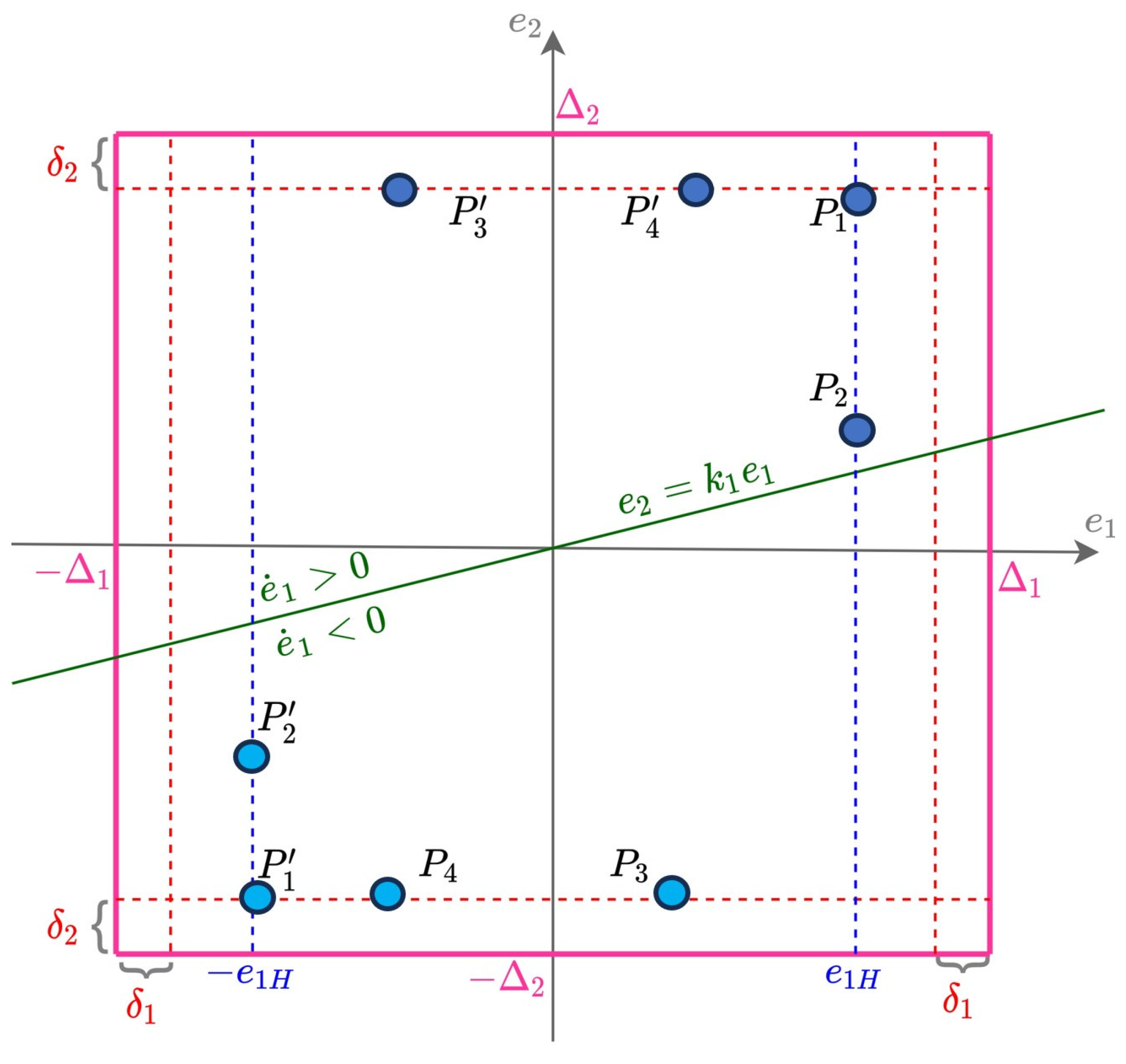
Let us further assume that position and velocity are measured with absolute error amplitudes smaller than δ 1 and δ 2 , respectively, due to measurement noise, quantization, etc. Since measurements that violate the tracking error constraints are unacceptable for the controller, the practical constraints e i Δ i δ i must be respected during operation. The system behavior will be analyzed using the ‘error plane’ presented in Figure 6.
The figure illustrates the constraints Δ i ,   Δ i , and the reduced constraints Δ i + δ i ,   Δ i δ i ,   i = 1,2 . According to Equation (12), the line k 1 e 1 + e 2 = 0 separates the regions where the position error derivative is positive or negative. The inclination of this line depends on selected gain k 1 : Specifically, the line rotates counterclockwise as k 1 increases. The lines ± e 1 H indicate critical positions at which the extremal control inputs u M are required to reverse motion and push the position error away from the barrier ± Δ 1 δ 1 .
Consider the scenario where e 1 = e 1 H > 0 ,   e 2 = e 20 ,   e 20 e 2 H : = Δ 2 δ 2 > 0 (points P 1 or P 2 in Figure 6). If k 1 > e 20 / e 1 H , then e ˙ 1 < 0 , causing e 1 to decrease and move away from the critical line e 1 = e 1 H . Conversely, if k 1 < e 20 / e 1 H , then e ˙ 1 > 0 , and e 1 increases towards the critical line e 1 = Δ 1 δ 1 . This motion must be arrested using the maximum control effort u M (positive e 1 means that the velocity x 2 should be increased to decrease the distance x 1 d x 1 ). Therefore, the actual control, defined by Equation (19), must satisfy the following inequality:
u = f ^ T φ x 1 , x 2 + κ 1 K 1 e 1 H K 2 ( e 20 ) e 1 H + κ 2 ( e 20 ) e 2 H + 1 2 σ K 2 e 20 e 20 u M
As only the first term may by negative, the sufficient condition for κ 1 to satisfy inequality (39) for any e 20 (noting that that K 2 e 2 H > K 2 ( e 20 ) ) is as follows:
κ 1 K 2 e 2 H K 1 e 1 H u M + max f ^ T φ x 1 , x 2 e 1 H κ 1 H .
Assuming that the maximum negative control u M is applied, the inequality e ˙ 2 < U M u M I u M < 0 (see (38)) holds (where I u M denotes the upper bound of I u ). Therefore, e 2 strictly decreases:
e 2 t e 20 + U M u M I u M t .
Using Equation (12), the position tracking error evolves according to the following:
e 1 t = e 1 H + 0 t k 1 e 1 τ + e 2 τ d τ e 1 H + 0 t e 2 τ d τ e 1 H + 0 t e 20 + U M u M I u M τ d τ = e 1 H + e 20 t + U M u M 2 I u M t 2 .
The right-hand side of (42) reaches a maximum at t = t m a x e 20 I u M u M U M , yielding the maximum value: e 1 M e 1 H + 1 2 e 20 2 I u M u M U M . Therefore, to ensure that the position error e 1 starting from e 1 H (i.e., the value of the position tracking error, which triggers u t = u M ) never exceeds the constraint Δ 1 δ 1 (for any e 20 ), it is sufficient to select the following:
e 1 H Δ 1 δ 1 1 2 e 20 2 I u M u M U M Δ 1 δ 1 1 2 e 2 H 2 I u M u M U M ,
This condition provides a conservative but practical estimate of e 1 H , which does not depend on the gain k 1 . A more accurate estimation of e 1 H could be obtained by solving exactly Equations (12) and (41) with the condition e 1 = e 1 H . But the simpler condition (43) allows for off-line, a priory estimation, which is independent on other tuning parameters, especially on the gain k 1 .
Similarly, while the gain κ 1 is responsible for obtaining maximal control pushing away e 1 from the barrier Δ 1 δ 1 , the coefficient κ 2 ( e 2 ) governs pushing e 2 away from Δ 2 δ 2 . Let us consider a point such as P 3 or P 4 in Figure 6, where e 1 Δ 1 δ 1 and e 2 = e 2 H . In this case, a positive control input u M > U M will cause e 2 to decrease, pushing the velocity error away from its barrier. Therefore, the inequality:
u = f ^ T φ x 1 , x 2 + κ 1 K 1 e 1 K 2 ( e 2 H ) e 1 + κ 2 ( e 2 H ) e 2 H + 1 2 σ K 2 e 2 H e 2 H u M
should be satisfied. As only two terms, f ^ T φ x 1 , x 2 and κ 1 K 1 e 1 K 2 ( e 2 H ) e 1 (if e 1 < 0 ), can be negative, the sufficient condition for the inequality (44) is as follows:
κ 2 e 2 H κ 2 H : = u M + max f ^ T φ x 1 , x 2 + κ 1 K 1 e 1 H K 2 ( e 2 H ) e 1 H e 2 H   u M + max f ^ T φ x 1 , x 2 + κ 1 K 1 e 1 K 2 ( e 2 H ) e 1 e 2 H
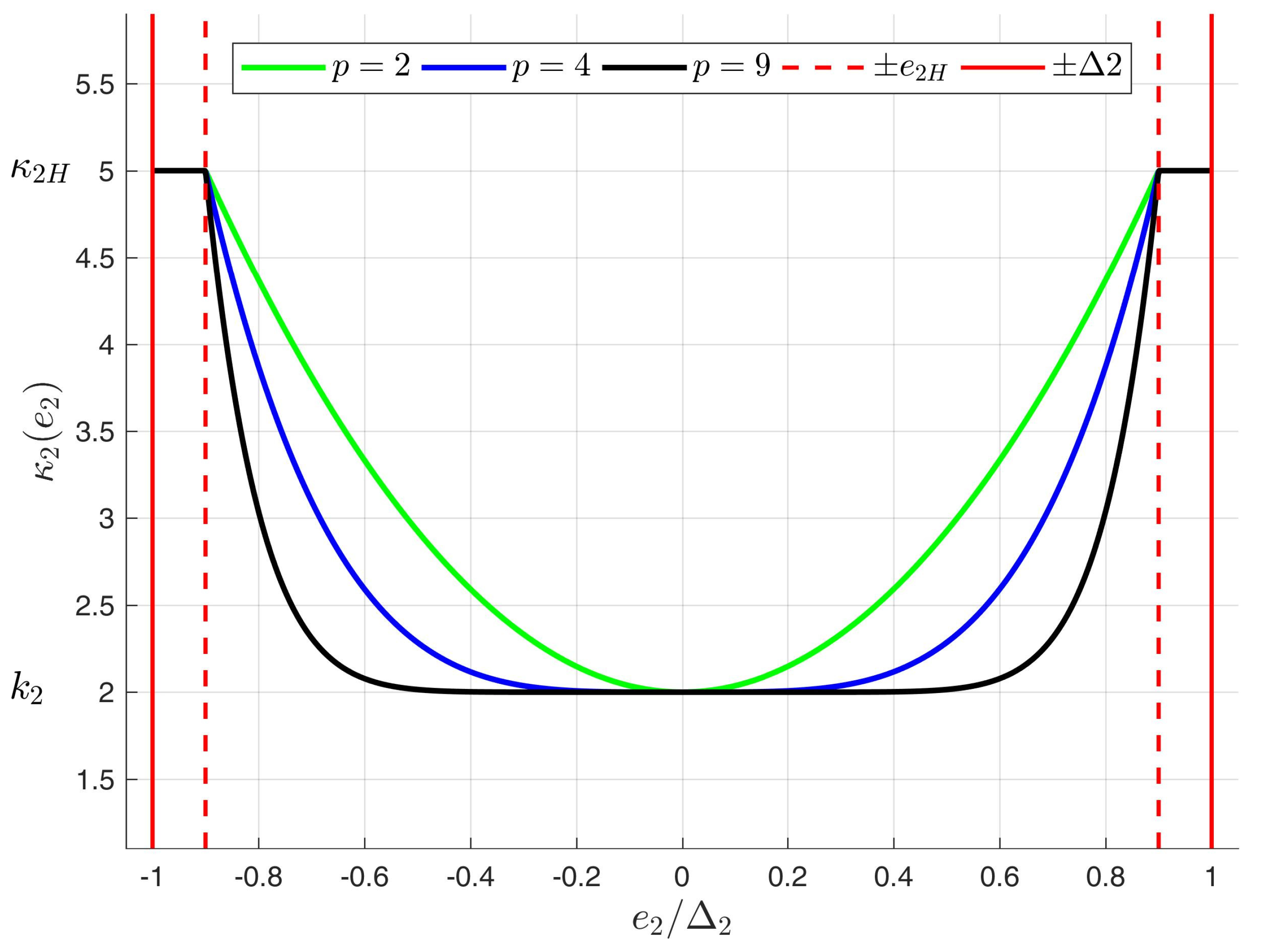
As the gain κ 2 e 2 is supposed to change from the value k 2 near e 2 , to κ 2 H for e 2 = e 2 H , we propose to shape κ 2 e 2 according to the following:
κ 2 e 2 = k 2 + κ 2 H k 2 tanh s a t 1 ρ   a t a n h e 2 e 2 H p ,
where p shapes the curve, as it is shown in Figure 7, and small ρ serves for the numerical safety.
A similar analysis can be applied to the negative constraints Δ 1 + δ 1 ,   e 1 H ,   Δ 2 + δ 2 (points P 1 , P 2 , P 3 , P 4 in Figure 6). This analysis confirms that if the critical triggering control threshold e 1 H and gains κ 1 H ,   κ 2 H are selected in accordance with inequalities (43), (40), and (45), respectively, then the tracking error remains within the constraints e i Δ i δ i ,   i = 1,2 .

4.2. Detailed Tuning Procedure

The previous analysis leads to a systematic method for tuning the parameters of the proposed controller. The procedure is as follows:
  • Consider the desired trajectory and the derivatives x 1 d ,   x ˙ 1 d ,   x ¨ 1 d and find the range of each.
  • Consider the model and specify the functions φ x 1 , x 2 modeling the external forces/torques. Decide if the modeling uncertainty ε is present or not ( ε = 0 ) . Decide the compensating parameter σ .
  • Consider the model parameters and select the constraints for adaptive parameters f m ,   f M , and the initial guess f ^ ( 0 ) . Select the parameters Γ that govern the speed of adaptation.
  • Consider the measurement errors and noises and select δ 1 ,   δ 2 .
  • Decide the tracking error constraints Δ 1 ,   Δ 2 . Compute e 2 H = Δ 2 δ 2 .
  • Select acceptable constraint 12 for x ˙ 1 d x 2 and calculate the gain k 1 from (32).
  • Estimate U M max I u ( x ¨ 1 d k 1 2 e 1 + k 1 e 2 + max F u x 1 , x 2 . Check if u M < U M . If not, your servo is not able to track the desired trajectory.
  • Calculate e 1 H from (43).
  • Calculate κ 1 H from (40) for any combination of BLFs V 1 ,   V 2 you consider. Select the smallest κ 1 H , the pair V 1 ,   V 2 , which corresponds to this selection, and choose κ 1 κ 1 H .
  • Select k 2 , checking the eigenvalues of the simplified system (33).
  • Calculate κ 2 H from (45). Form κ 2 ( e 2 ) according to (46).
Parameters used by the presented tuning procedure are summarized in Table 7.
Table 7. Parameters used in the tuning procedure.
ParameterDescriptionUsed in:
U M Minimal control range required to solve the tracking problem.(38)
Δ 1 ,   Δ 2 Constraints imposed on tracking errors.Figure 6
δ 1 ,   δ 2 Estimates of position and velocity measurement noise.Figure 6
12 Acceptable   constraint   for   x ˙ 1 d x 2 .(23)
k 1 Controller gain (position control loop).(23)
e 1 H Critical value of position tracking error triggering maximum control.(43)
κ 1 H Critical   value   of   the   controller   gain   κ 1 .   It   corresponds   to   the   pair   of   BLFs   V 1 ,   V 2 (40)
κ 1 Controller   gain   responsible   for   obtaining   maximal   control ,   pushing   away   e 1   from   the   barrier    Δ 1 δ 1 .(40)
V 1 ,   V 2 Selected BLFs for position and velocity control loop. (40)
k 2 Controller gain (position control loop).(33)
e 2 H e 2 H = Δ 2 δ 2 Critical   value   of   position   tracking   error   triggering   maximum   gain   κ 2 ( e 2 ) .Figure 6
κ 2 H Value   of   variable   gain   κ 2 ( e 2 )   achieved   for   e 2 = e 2 H (45)
κ 2 ( e 2 ) Variable   gain ,   which   governs   pushing   e 2   away   from   Δ 2 δ 2 (46)
The presented procedure requires preliminary estimation of model uncertainties and measurement noise. Some parametric uncertainties can be estimated based on manufacturer data (e.g., the torque/force-to-current constant k u ), while others require knowledge of the planned servo operation (such as variations in load mass during motion execution) or even identification experiments (e.g., friction characterization).
Measurement noise limits can be estimated based on hardware specifications—such as encoder resolution—and the selected sampling time. Proper estimation of uncertainties and noise levels is crucial: Overestimating uncertainties can degrade system performance, while underestimating them may lead to system malfunction.
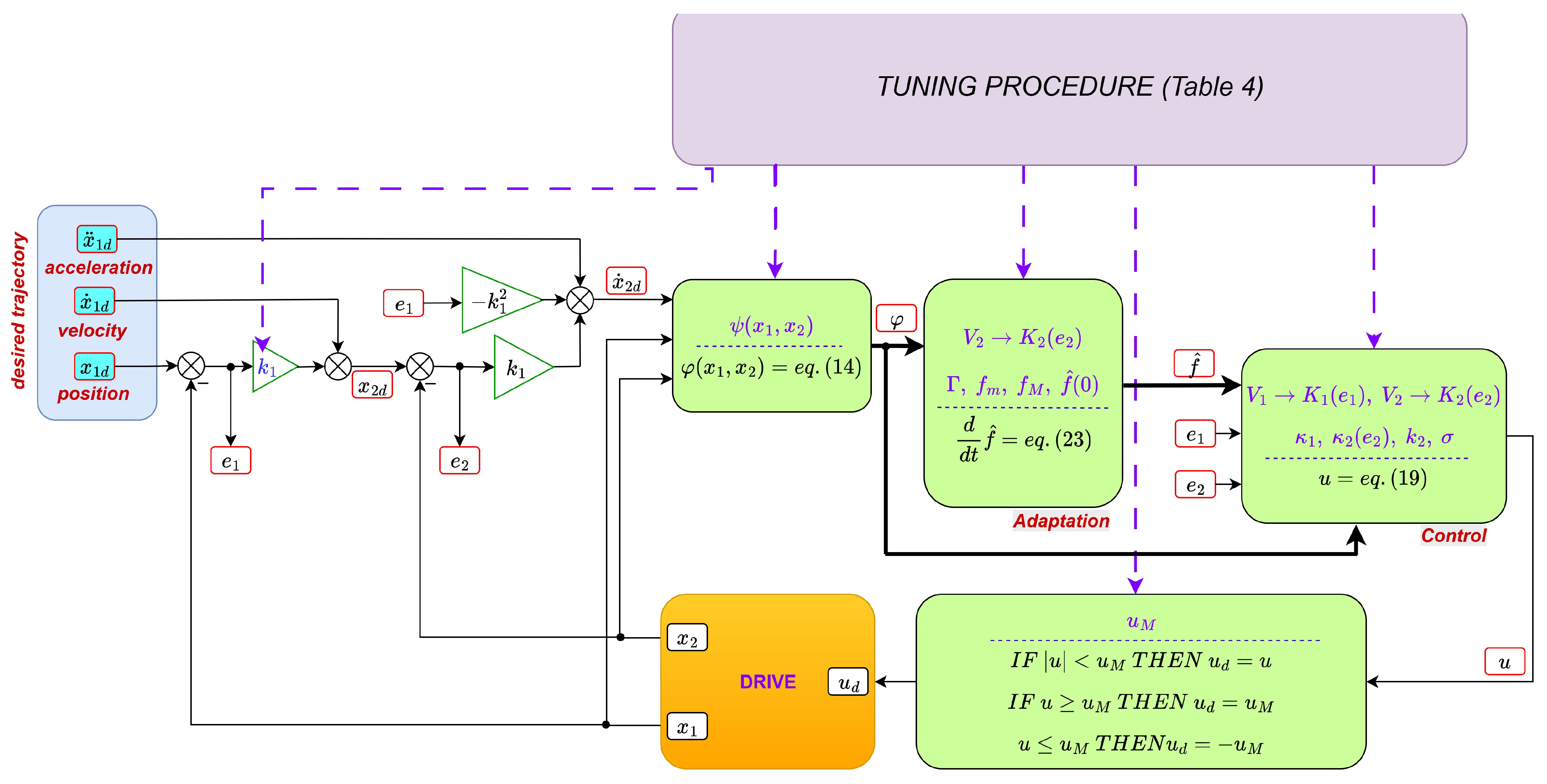
A complete diagram of the control system, illustrating the influence of the tuning procedure on the controller parameters, is presented in Appendix A.

5. Implementation of BLF-Based Controllers

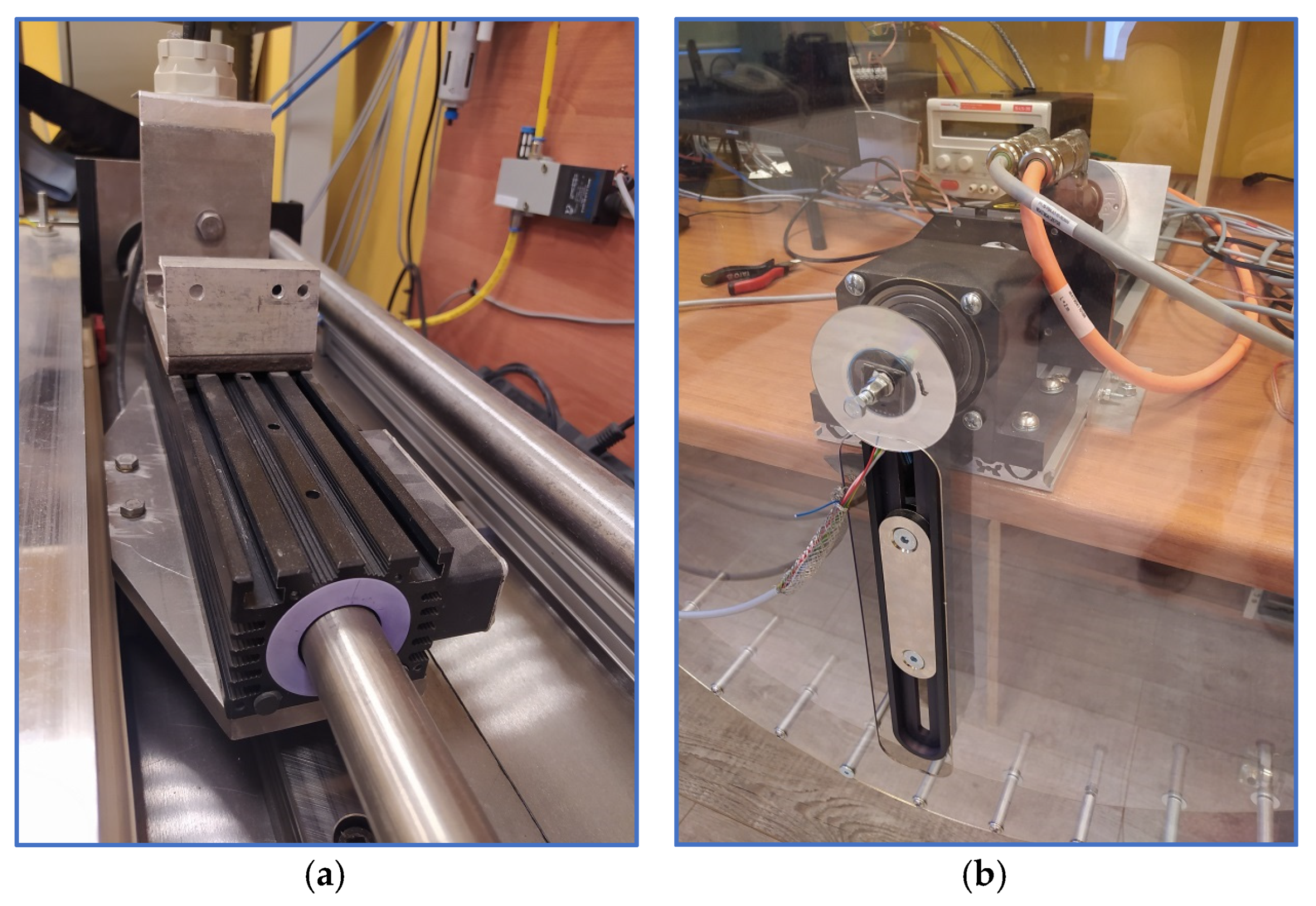
The control algorithm derived in the previous sections, along with the proposed tuning procedure, was implemented and validated on two physical servo systems, shown in Figure 8. The first system employs a linear permanent magnet motor (LPMM), designed for precise translational motion. The second system is based on a permanent magnet synchronous motor (PMSM), which provides rotational actuation of a heavy arm.
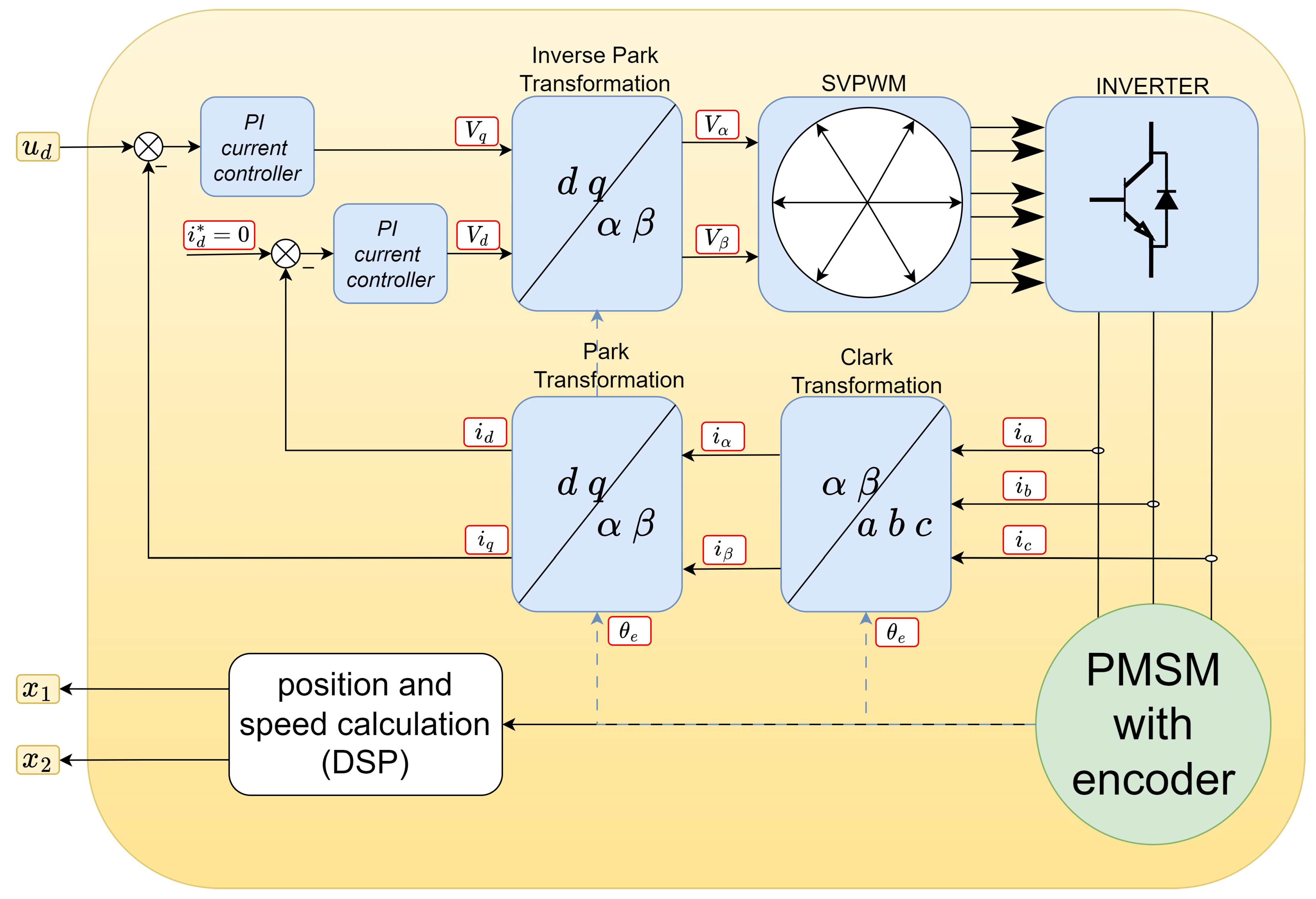
Both drives operate under current-control mode, facilitated by internal pulse–width modulation (PWM) converter controllers. These inner-loop current controllers are responsible for accurately regulating the motor currents, enabling the outer-loop position and velocity control to rely on torque-level actuation.

5.1. Linear Servo

The first experimental system utilizes a linear permanent magnet motor (LPMM) for precise translational motion. The dynamics of this system were modeled with sufficient accuracy by the following set of equations:
x ˙ 1 = x 2 m x ˙ 2 = k u u a   t a n h 100 x 2 b x 2 ,
where x 1 denotes the linear position, x 2 —velocity, m is the mass of the moving part, and the term a   t a n h 100 x 2 + b x 2 models nonlinear and viscous friction. The motor constant k u = 39   N / A is provided by the manufacturer, and u states for the motor current. The time constant of the current control loop was determined in [38] and is 0.46   m s while the mechanical time constant is m b = 8   k g 25   N s m = 0.32   s . Because the inner-loop current controller operates with a very short time constant, the motor current u is directly treated as the input signal. The maximum allowable current, constrained by hardware limits, is u < u M = 2.67   A , and this constraint must not be violated during control execution.
The desired position trajectory follows the profile illustrated in Figure 2, ranging from 0 to 0.6 m. The corresponding maximum velocity and acceleration are x ˙ 1 d M = 0.7   m / s and acceleration is x ¨ 1 d M = 2   m / s 2 . This trajectory was generated by triple-integrating the jerk profile x 1 d under zero initial conditions.
Before implementing the controller on the physical servo, it was first tested in simulation using a digital twin of the system. The simulation model is derived from Equation (47), with parameters I u = m / k u = 0.154 , g 1 = a / k u = 0.128 , and g 2 = b / k u = 0.513 . All parameters are expressed in SI units.
The tuning procedure described in Section 4 was applied.
  • Consider the desired trajectory and the derivatives x 1 d ,   x ˙ 1 d ,   x ¨ 1 d —the maximum values are provided above.
  • Consider the model and decide the functions φ x 1 , x 2 modeling the external forces/torques. Decide if the modeling uncertainty ε is present or not ( ε = 0 ) . Decide the compensating parameter σ . We assume that the model is accurate: ε = 0 ,   σ = 0 . The linear-in-parameters model (14) is as follows:
    f T = m k u a k u b k u ,    φ x 1 , x 2 = x ˙ 2 d t a n h 100 x 2 x 2 .
  • Consider the model parameters and select the constraints for adaptive parameters f m ,   f M , and the initial guess f ^ ( 0 ) . Decide the parameters responsible for the speed of adaptation Γ . We are able to estimate the maximum values of the unknown parameters, therefore f m = 0 ,   f M T = 0.25 0.154 0.60 ,   f ^ 0 = 0 . Γ = d i a g { 100   30   300 } . Parameters Γ can be improved during simulation if this initial guess is not perfect.
  • Consider the measurement errors and noises and select δ 1 ,   δ 2 . The position was measured by an optical encoder with the resolution of 1   μ m . Therefore, δ 1 = 10 6   m was accepted. The velocity was calculated from the position data using a dedicated observer. The expected error is not bigger then δ 2 = 0.005   m / s .
  • Decide the tracking error constraints Δ 1 ,   Δ 2 . Calculate e 2 H = Δ 2 δ 2 . It was assumed the position should be tracked with the error smaller then Δ 1 = 50   μ m , and that the error e 2 should be constrained by Δ 2 = 3 δ 2 = 0.015   m / s . Hence, e 2 H = Δ 2 δ 2 = 0.010   m / s .
  • Select acceptable constraint 12 for x ˙ 1 d x 2 and calculate the gain k 1 from (32). It is assumed x ˙ 1 d x 2 Δ 12 = 0.02   m / s . This leads to the maximum value of the gain k 1 from (32): k 1 = 100 .
  • Estimate U M max I u ( x ¨ 1 d k 1 2 e 1 + k 1 e 2 + max F u x 1 , x 2 . Check if u M < U M . If not, your servo is not able to track the desired trajectory. Taking into account maximum values of parameters f M , the maximum of x ˙ 1 d , the range of e 1 ,   e 2 and x 1 ,   x 2 we are able to estimate U M = 1.52   A . Therefore, with u M = 2.67   A , the servo is able to track the desired trajectory despite of the uncertainties.
  • Calculate e 1 H from (43). e 1 H = 38.1   μ m
  • Calculate κ 1 H from (40) for any combination of BLFs V 1 ,   V 2 you consider. Select the smallest κ 1 H , the pair V 1 ,   V 2 , which corresponds to this selection, and choose κ 1 κ 1 H . The values of κ 1 H calculated from (40) for any combination of BLFs from Table 2 are presented in Table 8. The smallest one is 7.75 · 10 3 for V 1 = t a n 2 -BLF and V 2 = a t a n h -BLF. Therefore, κ 1 = 7.75 · 10 3 , and this set of BLFs are selected.
  • Select k 2 , checking the eigenvalues of the simplified system (33). The gain k 2 = 113 provides eigenvalues of system (33) 276   ±   j 4.9 , which assures a satisfactory transient of system (33).
  • Calculate κ 2 H from (45). Form κ 2 ( e 2 ) according to (46). Using (45) results in κ 2 H = 6.38 · 10 5 , and function (46) is used with parameter p = 4 .
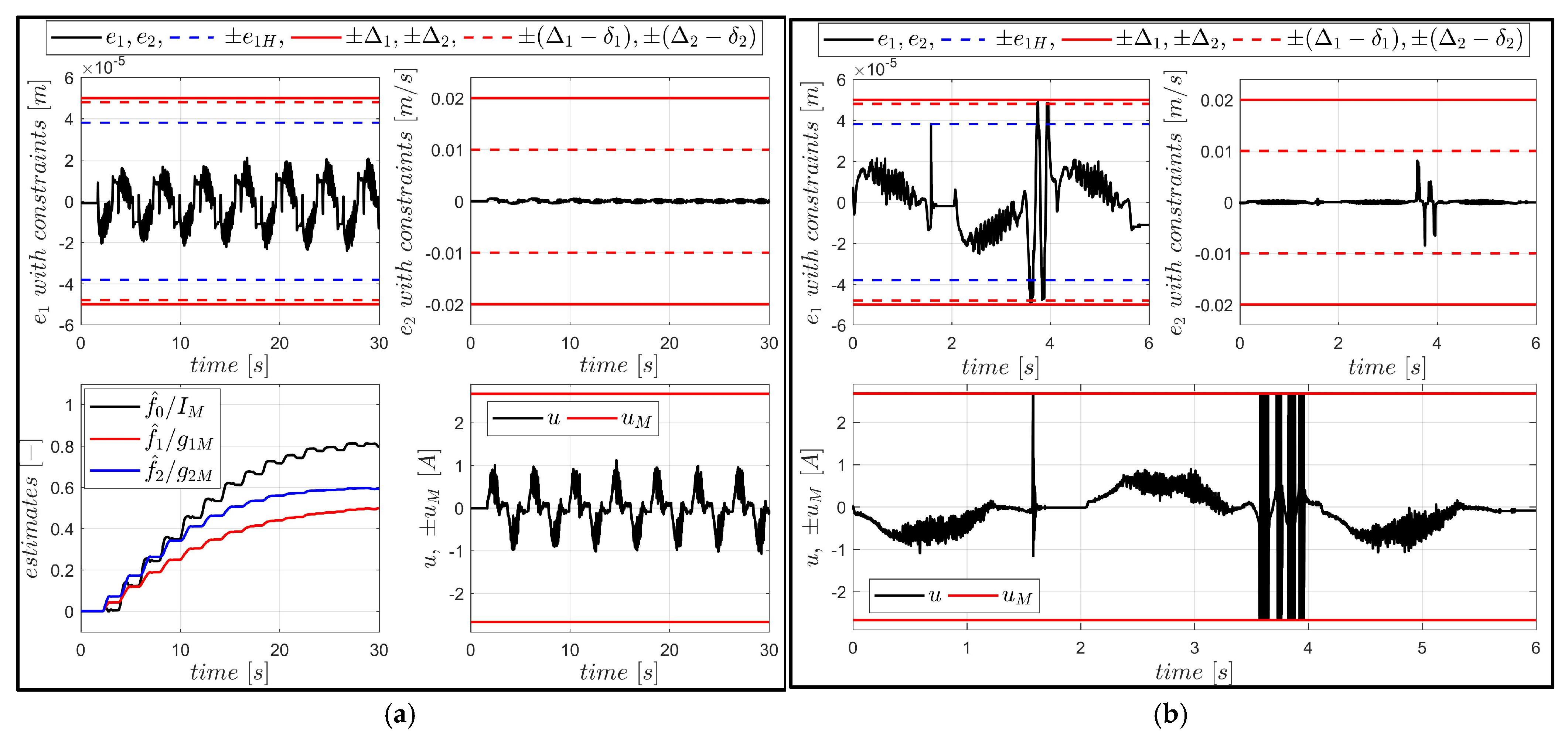
The simulation outcomes for the linear servo system are presented in Figure 9a. The model of the servo is based on Equation (47). To evaluate the robustness of the proposed controller, a ripple force with a small amplitude ( 1   N )—representing a bounded external disturbance, not considered during controller derivation—was introduced into the simulation model. Moreover, the operation of a real encoder (with the actual resolution) was simulated. The velocity was calculated using the data from the encoder model. Initial conditions were: x 1 0 = e 1 H , x 2 0 = 0 .
Despite these perturbations, the closed-loop system maintained stable operation:
  • All position and velocity constraints were respected;
  • The tracking errors converged to a small neighborhood of zero. This convergence is very fast, and quasi-steady-state oscillations result from the ripple force and measurement errors;
  • The adaptive parameters remained bounded;
  • And the control input remained within the actuator limits.
These results confirm the effectiveness and robustness of the proposed adaptive BLF-based control scheme under external disturbances and modeling uncertainties.
To illustrate the influence of barrier Lyapunov function (BLF) selection on system performance, a comparative simulation was conducted using an alternative BLF configuration:
V 1 = a t a n h - BLF   and   V 2 = t a n - BLF
This configuration led to the following gain values: κ 1 = 1.12 · 10 5 , κ 2 H = 4.56 · 10 3 , k 2 = 361 .
The results of this simulation are shown in Figure 9b. The controller with higher gain values also demonstrated stable and correct operation. We can observe that the quasi-steady-state tracking errors were further reduced compared to the first case. However, this improvement came at a cost: the current signal quality noticeably degraded.
To verify the simulation outcomes and the practical feasibility of the proposed controller, the configuration using V 1 = t a n 2 -BLF and V 2 = a t a n h -BLF was implemented on a real linear servo system. The real-time controller was deployed on a DSP board with a sampling time of 50 μs.
The experimental results are presented in Figure 10a and Table 9. The observed behavior closely replicates the simulation outcomes:
  • Tracking performance is accurate—the QSS tracking error does not exceed twice the encoder resolution.
  • All imposed state and input constraints are strictly respected.
  • Adaptive parameters evolve smoothly and remain bounded.
  • The selection of the BLF combination affects the quality of the control signal (measured by SNR).
To further validate the robustness of the controller, an external disturbance—an unexpected force acting on the motor forcer—was applied during the operation. The response is shown in Figure 10b. Although the disturbance was not necessarily small, the controller successfully maintained:
  • Constraint satisfaction for both tracking errors and control input,
  • Stability and convergence, allowing the system to quickly recover and resume accurate tracking once the disturbance disappeared.
These results confirm the practical applicability, robustness, and real-time implementability of the proposed BLF-based adaptive control algorithm under realistic operating conditions.

5.2. Rotational Servo

In the second case study, a rotational servo based on a permanent magnet synchronous motor (PMSM) is used to actuate a massive arm subject (see Figure 8b). The primary external disturbance in this system is the torque caused by gravity, which depends nonlinearly on the arm’s angular position.
As with the linear servo, the motor current is used as the control input. This is justified by the high bandwidth of the internal PWM inverter’s current loop. The negligible difference between the desired and actual currents, as it is illustrated in Figure 12b discussed later, confirms that the current controller introduces no significant dynamics. Accordingly, the plant dynamics are modeled as follows:
x ˙ 1 = x 2 J x ˙ 2 = k u u c   s i n x 1
where x 1 and x 2 denote angular position and velocity, J is the moment of inertia, k u is the torque constant, c denotes amplitude of the load torque, and u is the motor current. The time constant of the current control loop was determined in [40] and is 0.4 ms, while the mechanical time constant is 3.25   s . Because the inner-loop current controller operates with a very short time constant, the motor current u is directly treated as the input signal. As before, prior to real-plant implementation, the control system was validated through simulation. The ‘digital twin’ of the real servo was governed by (49) with parameters J = 0.0265   k g m 2 , k u = 0.147   N m / A , c = 1.36   N m , and current constraint u < u M = 19.9 A . The desired angular position trajectory was generated in the same manner as in the previous case (Figure 2). The complete tuning process for this servo, based on the procedure detailed in Section 4, is summarized in Table 10.
The controller was initially tested in simulation using the digital twin of the rotational servo. Once correct behavior was verified, it was implemented on the real system using a DSP board with a sampling time of 50   μ s .
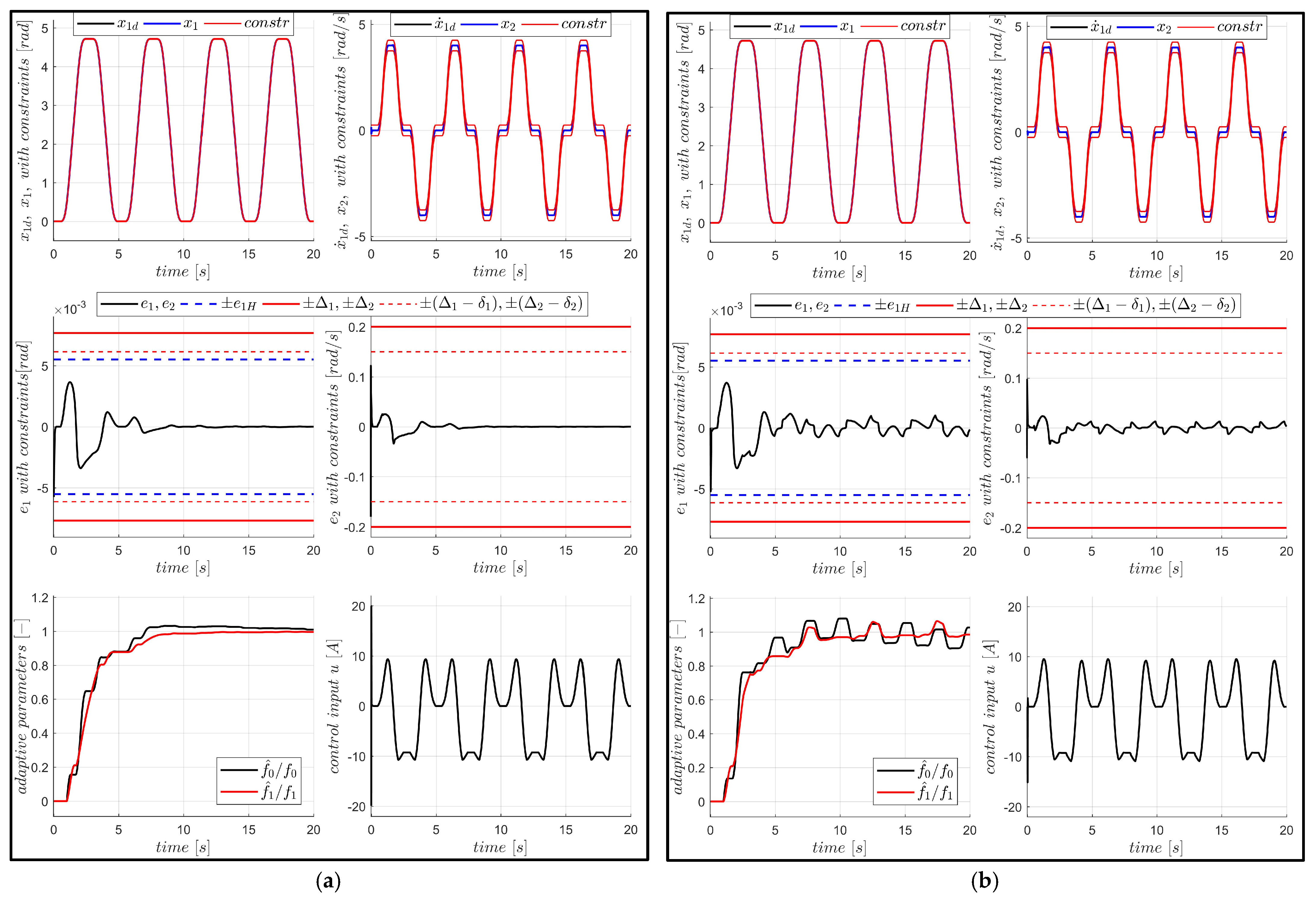
During the first experiment the servo was modeled by Equation (49) starting from e 1 0 = e 1 H ,   e 2 0 = 0.99 Δ 2 . The results presented in Figure 11a confirm proper and accurate closed-loop operation. All imposed constraints are strictly satisfied, the tracking errors converge to zero, and the adaptive parameters converge to the exact values of model parameters.
Figure 11. Servo operation with V 1 = t a n 2 -BLF and V 2 = a t a n h -BLF (a) with the idealized model of servo; (b) with the realistic model of servo.
Energies 18 04301 g011
During the second test, some factors omitted in the controller design were included in the servo model: the friction torque, the quantized position measurement, and the dynamics of the velocity observer. The results, presented in Figure 11b, confirm proper closed-loop operation, despite all these disturbances. All imposed constraints are strictly satisfied, the tracking errors converge to a small neighborhood around zero, and the adaptive parameters remain bounded throughout the motion. These results demonstrate both the effectiveness and robustness of the proposed control algorithm in managing nonlinear disturbances and handling control constraints.
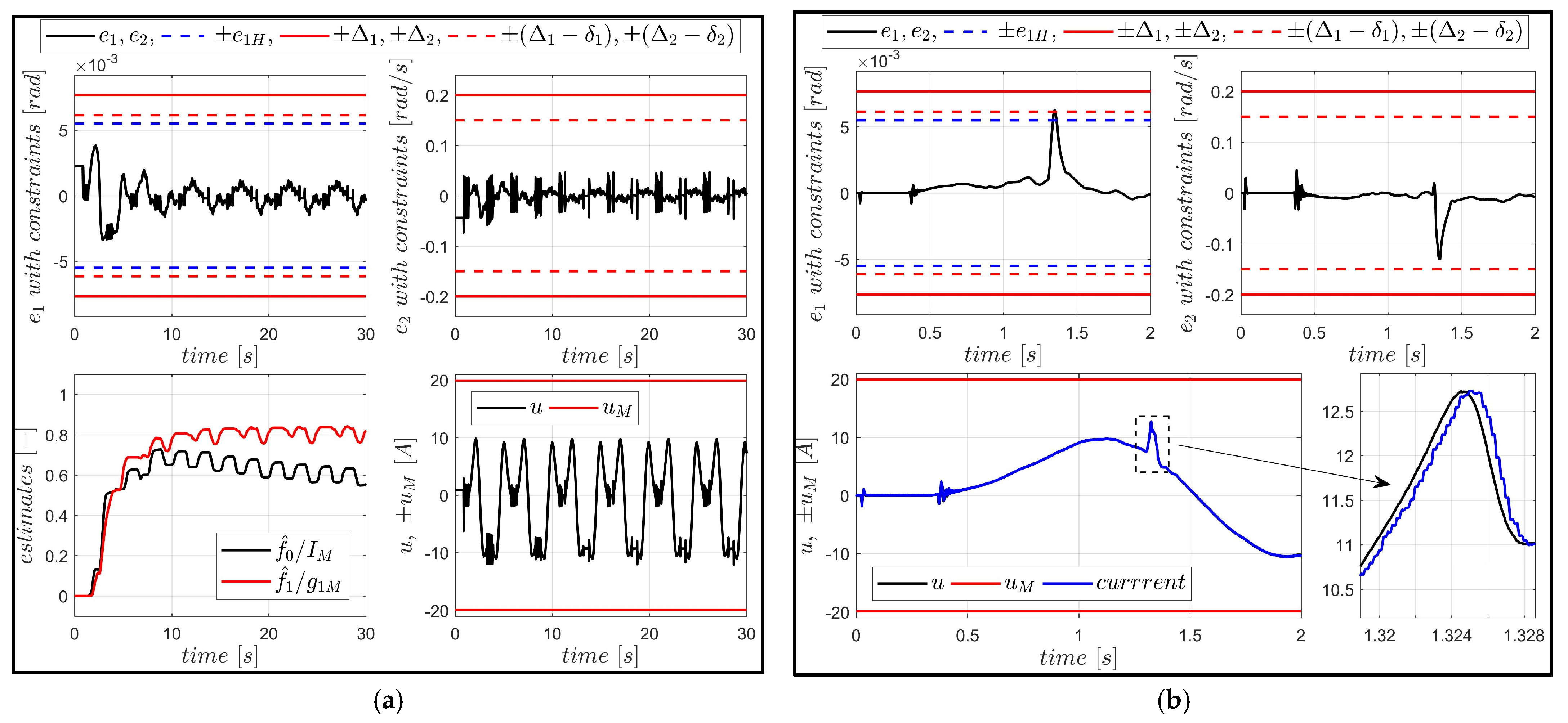
The proposed controller was also implemented in the real rotational servo system. As illustrated in Figure 12a, the real servo tracks the desired trajectory accurately, with all imposed constraints being satisfied throughout the motion. The system’s robustness was further validated by applying unexpected external disturbances—torques acting on the rotating arm—which temporarily interrupted the quasi-steady-state operation. The results shown in Figure 12b demonstrate that the tracking errors and the control input remain within allowable limits during these disturbances. Once the disturbance vanishes, the controller successfully drives the system back to the desired trajectory, confirming its resilience and reliability in real-world operation.
Figure 12. Real servo operation with V 1 = t a n 2 -BLF and V 2 = a t a n h -BLF: (a) regular operation from the start; (b) response to a random external disturbance applied at 1.3 s.
Energies 18 04301 g012
The presented approach is designed to operate in the presence of model uncertainties and external disturbances. To address these challenges, adaptive control techniques are used to handle parametric uncertainties, while unstructured uncertainties account for modeling errors and external perturbations. The theoretical framework defines the class of uncertainties that can be managed such that uniformly ultimately bounded (UUB) stability is ensured, and both position and velocity constraints are satisfied.
The tuning procedure maintains these properties even under control saturation and measurement noise. Successful practical implementation demonstrates the robustness of the proposed approach to unmodeled dynamics, external disturbances, and various other real-world factors not included in the theoretical derivation.
Based on the results from both simulations and experiments, we can conclude that no computational or hardware limitations were encountered that would compromise system performance. The primary challenge lies in ensuring sufficient quality of velocity measurement—the main issue being excessive delay or phase shift, rather than measurement noise.
The computational burden of the proposed algorithm is moderate, and no difficulties were observed in performing calculations within the required sampling period. In fact, the system exhibited considerable robustness to variations in sampling frequency. However, it is important to note that changes in sampling frequency not only affect the delay in the current loop but also influence the noise content in speed estimation (derived from the encoder). This, in turn, necessitates an adjustment of the parameter δ 2 , resulting in different algorithm parameters.
Therefore, the sampling time should be determined prior to initiating the tuning procedure.

6. Conclusions

BLF-based technique continuously remains one of the most popular approaches to cope with state constraints. The new algorithm presented in this contribution is especially tailored for applications to control electric servos, which are supposed to track a desired (linear or angular) position. It is based on a simplified, second-order model of a servo, but it was demonstrated that this modeling approach is sufficiently accurate and justified. It covers the main sources of control difficulties—nonlinear external forces or torques, such as friction or a nonlinear load. The proposed approach allows for modeling uncertainty concerning model parameters as well as unstructured modeling errors or disturbances.
A distinctive feature of the proposed controller is that some extra tuning parameters were added to enable efficient and safe implementation in real applications, where the control variable is constrained. The problem of implementing the control algorithm in the presence of several factors not taken into account during theoretical derivation but common in practice was exhaustively investigated. Although control constraints and measurement errors were the main such factors considered in this paper, some others (like effects of discretization, delays, etc.) may be addressed in the same manner.
Practical safe operation of a servo is understood as remaining within the state constraints in any case—also when control constraints are active and the measurements are corrupted. It was proven that if the proposed BLF-based controller is applied, such safe operation is achieved by a proper tuning procedure, which was carefully derived and described. The main point is to activate maximum control pushing position and velocity away from a barrier. This must be performed in advance—when the tracking error achieves the critical value, which can be calculated beforehand if we are able to estimate maximum uncertainties. It was also stressed that the selection of specific BLFs used to derive the controller, although irrelevant for proving stability, has a strong influence on the practical implementation and control quality of a real system.
The proposed controller and the derived tuning procedure, aiming for practical safe operation of a servo, were confirmed in three ways: by a theoretical proof of stability using Lyapunov techniques, by extensive numerical simulations, and by laboratory experiments using two different servo systems—the first with a linear permanent magnet motor and the second with a rotational PMSM. All performed experiments demonstrate that the high control quality (fast transient response, accurate tracking) and safe operation (remaining within the state constraints) are not diminished even if severe unmodeled factors affect the actual, real system.
It was confirmed once again that, even if preliminary requirements impose constraints only on the position tracking error, it is advantageous to constrain the velocity tracking error as well. This provides a smoother trajectory and allows avoidance of rapid movements near the position-constraint boundary, which requires high control values. Proper choice of control system parameters is easier in the case of coexisting position and velocity constraints, as reported in [41].
In addition to safe operation within constraints, the proposed controller ensures good tracking accuracy of the desired trajectory, despite unknown drive parameters. In practical applications, we achieved a quasi-steady-state tracking error no greater than twice the position measurement resolution.
This paper focuses on controlling an electric servo with one degree of freedom. The primary objective is to solve the tracking problem under hard position and velocity constraints while accounting for a nonlinear motion equation (e.g., nonlinear loads such as friction) with unknown parameters, control saturation, and measurement noise. Given the widespread use of servo systems performing single-degree-of-freedom motion, this problem is of significant practical and theoretical relevance.
Controlling multi-degree-of-freedom motion using BLFs can be approached in several ways. One-dimensional BLFs can be applied to each motion direction individually [23]; constraints can be reduced to a scalar quantity, such as the norm of tracking errors [24]; or multi-dimensional BLFs can be employed. While the derivation of adaptive controllers differs across specific applications, the issues of control saturation and measurement noise are common and can often be addressed using similar techniques. This presents a promising direction for future research.
For the sake of brevity, the approach presented here focuses on symmetric, time-invariant BLFs. Generalization to asymmetric constraints is straightforward. Time-varying constraints, however, require separate analysis—specifically, triggering error thresholds must be computed dynamically throughout the transient response. Nonetheless, the core idea remains applicable, making this another promising research area.
A completely different approach is required in the case of integral BLFs, which impose constraints on the state variables rather than on tracking errors, and for zone-BLFs, which enable energy-saving behavior within allowable constraint boundaries.
Author Contributions

Conceptualization, M.J. and J.K.; methodology, M.J. and J.K.; software, M.J.; validation, M.J. and J.K.; writing—original draft preparation, M.J. and J.K.; writing—review and editing, M.J. and J.K. All authors have read and agreed to the published version of the manuscript.

Funding

This research was funded by the Politechnika Łódzka (Lodz University of Technology). The APC was funded by Politechnika Łódzka.

Data Availability Statement

The data are available from the corresponding author on demand.

Conflicts of Interest

The authors declare no conflicts of interest.

Abbreviations

The following abbreviations are used in this manuscript:
BLFBarrier Lyapunov Function
QLFQuadratic Lyapunov Function
CLFControl Lyapunov Function
LPMMLinear Permanent Magnet Motor
PMSMPermanent Magnet Synchronous Motor
UUBUniformly Ultimately Bounded
SNR Signal - to - Noise   Ratio :   S N R = A n o i s e 2 A s i g n a l 2 · 100 %
QSSQuasi-steady-state

Appendix A

The complete diagram of the control system, indicating the impact of the tuning procedure on the controller parameters, is presented in Figure A1.
Figure A1. Diagram of the closed-loop control system. Dashed arrows indicate the impact of the off-line tuning procedure on the controller parameters.
Energies 18 04301 g0a1
Figure A2. Hardware configuration diagram—the servo working in the current-control mode—block DRIVE from Figure A1.
Energies 18 04301 g0a2

References

  1. Tang, R.; Lin, H.; Liu, Z.; Zhou, X.; Gu, Y. Adaptive Neural Network Prescribed Time Control for Constrained Multi-Robotics Systems with Parametric Uncertainties. Mathematics 2024, 12, 1880. [Google Scholar] [CrossRef]
  2. Ma, X.; Hong, J.; Zhang, Q.; Meng, Z. Trajectory Planning and Control Method of Space Servo Manipulator System. In Proceedings of the IEEE International Conference on Computer and Communications, ICCC 2024, Chengdu, China, 2 April 2025; pp. 1417–1421. [Google Scholar] [CrossRef]
  3. Autsou, S.; Kudelina, K.; Vaimann, T.; Rassõlkin, A.; Kallaste, A. Principles and Methods of Servomotor Control: Comparative Analysis and Applications. Appl. Sci. 2024, 14, 2597. [Google Scholar] [CrossRef]
  4. Chen, Y.L.; Li, Z.; Chen, F.; Lin, H.; Ju, B.F.; Liu, Y. Development of an Optimized Three-Axis Fast Tool Servo for Ultraprecision Cutting. IEEE/ASME Trans. Mechatron. 2022, 27, 3244–3254. [Google Scholar] [CrossRef]
  5. Jia, B.; Pan, H.; Cai, Y.; Zhang, L.; Chen, X.; Chen, L. Enhancing the Absolute Positioning Accuracy of Welding Robots Based on Joint Error Compensation. Eng. Appl. Artif. Intell. 2025, 158, 111302. [Google Scholar] [CrossRef]
  6. Liu, Y.; Qie, T.; Feng, W.; Iu, H.H.C.; Fernando, T.; Wei, Z.; Zhang, X. A Novel Barrier Lyapunov Function-Based Online Learning Control Method for Solid Oxide Fuel Cell in DC Microgrids. IEEE Trans. Smart Grid 2025, 16, 2774–2790. [Google Scholar] [CrossRef]
  7. Cheng, M.; Zhou, J.; Qian, W.; Wang, B.; Zhao, C.; Han, P. Advanced Electrical Motors and Control Strategies for High-Quality Servo Systems—A Comprehensive Review. Chin. J. Electr. Eng. 2024, 10, 63–85. [Google Scholar] [CrossRef]
  8. Kavalieros, D.; Kapothanasis, E.; Kakarountas, A.; Loukopoulos, T. Methodology for Selecting the Appropriate Electric Motor for Robotic Modular Systems for Lower Extremities. Healthcare 2022, 10, 2054. [Google Scholar] [CrossRef]
  9. Hosseinnajad, A.; Mohajer, N.; Nahavandi, S. Barrier Lyapunov Function-Based Backstepping Controller Design for Path Tracking of Autonomous Vehicles. J. Intell. Robot. Syst. Theory Appl. 2024, 110, 118. [Google Scholar] [CrossRef]
  10. Dao, H.V.; Ahn, K.K. Active Disturbance Rejection Contouring Control of Robotic Excavators with Output Constraints and Sliding Mode Observer. Appl. Sci. 2022, 12, 7453. [Google Scholar] [CrossRef]
  11. Zhang, X.; Wang, Z.; Bai, C.; Zhang, S. A Novel Approach to Ripple Cancellation for Low-Speed Direct-Drive Servo in Aerospace Applications. Aerospace 2024, 11, 834. [Google Scholar] [CrossRef]
  12. Blanchini, F. Set Invariance in Control. Automatica 1999, 35, 1747–1767. [Google Scholar] [CrossRef]
  13. Ngo, K.B.; Mahony, R.; Jiang, Z.P. Integrator Backstepping Using Barrier Functions for Systems with Multiple State Constraints. In Proceedings of the 44th IEEE Conference on Decision and Control, and the European Control Conference, CDC-ECC ’05 2005, Seville, Spain, 15 December 2005; pp. 8306–8312. [Google Scholar] [CrossRef]
  14. Tee, K.P.; Ge, S.S.; Tay, E.H. Barrier Lyapunov Functions for the Control of Output-Constrained Nonlinear Systems. Automatica 2009, 45, 918–927. [Google Scholar] [CrossRef]
  15. Tang, Z.L.; Tee, K.P.; He, W. Tangent Barrier Lyapunov Functions for the Control of Output-Constrained Nonlinear Systems; IFAC: Oxford, UK, 2013; Volume 3, ISBN 9783902823458. [Google Scholar]
  16. Kabzinski, J.; Jastrzebski, M.; Mosiolek, P. Comparison of Various Barrier Lyapynov Functions for Adaptive Control of Nonlinear Systems. In Proceedings of the 2016 21st International Conference on Methods and Models in Automation and Robotics, MMAR 2016, Miedzyzdroje, Poland, 26 September 2016; pp. 1027–1032. [Google Scholar] [CrossRef]
  17. Xia, K.; Lee, S.; Son, H. Adaptive Control for Multi-Rotor UAVs Autonomous Ship Landing with Mission Planning. Aerosp. Sci. Technol. 2020, 96, 105549. [Google Scholar] [CrossRef]
  18. Wang, Z.; Zheng, H.; Zhang, G. Prescribed-Time-Based Anti-Disturbance Tracking Control of Manipulators Under Multiple Constraints. Actuators 2025, 14, 157. [Google Scholar] [CrossRef]
  19. Wu, L.; Zhao, D. Control of Vehicle Lateral Handling Stability Considering Time-Varying Full-State Constraints. Mathematics 2025, 13, 1217. [Google Scholar] [CrossRef]
  20. Hejrati, M.; Mustalahti, P.; Mattila, J. Robust Immersive Bilateral Teleoperation of Beyond-Human-Scale Systems with Enhanced Transparency and Sense of Embodiment. arxiv 2025, arXiv:2505.14486. Available online: http://arxiv.org/abs/2505.14486 (accessed on 9 July 2025).
  21. Singh, A.; Jain, A. Range-Only Dynamic Output Feedback Controller for Safe and Secure Target Circumnavigation. arxiv 2025, arXiv:2501.08058. Available online: http://arxiv.org/abs/2501.08058 (accessed on 9 July 2025).
  22. Song, Y.; Wu, Y.; Chen, Y. Control Design for Flexible Manipulator Model with Nonlinear Input and State Constraints Based on Symmetric Barrier Lyapunov Function. Symmetry 2025, 17, 1035. [Google Scholar] [CrossRef]
  23. Cao, Y.; Li, T. Nonlinear Antiswing Control for Shipboard Boom Cranes with Full State Constraints. Appl. Ocean. Res. 2024, 146, 2281–2292. [Google Scholar] [CrossRef]
  24. Xu, J.; Wang, H.; Tian, Y. Digital Human Model and Training Task Planning-Based Adaptive Assist-as-Needed Control for Upper Limb Exoskeleton. Mechatronics 2025, 110, 16037–16055. [Google Scholar] [CrossRef]
  25. Shi, Q.; Wang, R.; Li, X.; Yang, J. Barrier Lyapunov Function-Based Adaptive Optimized Control for Full-State and Input-Constrained Dynamic Positioning of Marine Vessels with Simulation and Model-Scale Tests. Ocean. Eng. 2024, 301, 117534. [Google Scholar] [CrossRef]
  26. Abhinav, K. Barrier Lyapunov Function Based Guidance Law Design for Gap Traversal of Aerial Vehicles. ISA Trans. 2025, in press. [Google Scholar] [CrossRef] [PubMed]
  27. Guo, C.; Xie, X.J.; Hou, Z.G. Removing Feasibility Conditions on Adaptive Neural Tracking Control of Nonlinear Time-Delay Systems With Time-Varying Powers, Input, and Full-State Constraints. IEEE Trans. Cybern. 2022, 52, 2553–2564. [Google Scholar] [CrossRef] [PubMed]
  28. Zhang, Y.; Wang, X.; Wang, Z. Removing the Feasibility Conditions Imposed on Full-State Constraint Control Design for Discrete-Time Nonlinear Systems. IEEE Trans. Circuits Syst. II Express Briefs 2024, 71, 2684–2688. [Google Scholar] [CrossRef]
  29. Wang, Y.; Wu, Z. Control Lyapunov-Barrier Function-Based Safe Reinforcement Learning for Nonlinear Optimal Control. AIChE J. 2024, 70, 108508. [Google Scholar] [CrossRef]
  30. Liu, B.; Hou, M.; Ni, J.; Li, Y.; Wu, Z. Asymmetric Integral Barrier Lyapunov Function-Based Adaptive Tracking Control Considering Full-State with Input Magnitude and Rate Constraint. J. Frankl. Inst. 2020, 357, 9709–9732. [Google Scholar] [CrossRef]
  31. Jastrzebski, M.; Kabzinski, J.; Mosiołek, P. Finite-Time, Robust, and Adaptive Motion Control with State Constraints: Controller Derivation and Real Plant Experiments. Energies 2022, 15, 934. [Google Scholar] [CrossRef]
  32. Xia, Y.; Li, J.Y.; Song, Y.K.; Wang, J.X.; Han, Y.F.; Xiao, K. Prescribed Performance-Tangent Barrier Lyapunov Function for Adaptive Neural Backstepping Control of Variable Stiffness Actuator with Input and Output Constraints. Int. J. Control Autom. Syst. 2023, 21, 975–992. [Google Scholar] [CrossRef]
  33. Liu, Y.H.; Liu, Y.; Liu, Y.F.; Su, C.Y. Adaptive Fuzzy Control With Global Stability Guarantees for Unknown Strict-Feedback Systems Using Novel Integral Barrier Lyapunov Functions. IEEE Trans. Syst. Man. Cybern. Syst. 2022, 52, 4336–4348. [Google Scholar] [CrossRef]
  34. Li, S.; He, P.; Lin, X. Asymmetrical Barrier Function-Based Adaptive Vibration Control for Nonlinear Flexible Cantilever Beam with Obstacle Restriction. IEEE Access 2021, 9, 58306–58318. [Google Scholar] [CrossRef]
  35. Liang, X.; Ge, S.S. Zone Barrier Lyapunov Functions for State Constrained Systems. IEEE Trans. Instrum. Meas. 2023, 72, 3001911. [Google Scholar] [CrossRef]
  36. Ding, K.; Zhang, X.; Nan, Y.; Zhuang, M. Fixed Time Adaptive Fuzzy Control of Nonlinear Systems with Time-Varying State Constraints. Autom. Control. Comput. Sci. 2024, 58, 43–57. [Google Scholar] [CrossRef]
  37. Kabziński, J.; Jastrzębski, M. Practical Implementation of Adaptive Friction Compensation Based on Partially Identified LuGre Model. In Proceedings of the 2014 19th International Conference on Methods and Models in Automation and Robotics, MMAR 2014, Miedzyzdroje, Poland, 20 November 2014; pp. 699–704. [Google Scholar] [CrossRef]
  38. Kabziński, J. Fuzzy Friction Modeling for Adaptive Control of Mechatronic Systems. In Proceedings of the Artificial Intelligence Applications and Innovations, Halkidiki, Greece, 27–30 September 2012; Iliadis, L., Maglogiannis, I., Papadopoulos, H., Eds.; Springer: Berlin/Heidelberg, Germany, 2012; pp. 185–195. [Google Scholar]
  39. Ioannou, P.; Baldi, S. Robust Adaptive Control; PTR Prentice-Hall: Upper Saddle River, NJ, USA, 2018; ISBN 9781420073676. [Google Scholar]
  40. Jastrzębski, M.; Kabziński, J.; Mosiołek, P. Adaptive Position Control for Two-Mass Drives with Nonlinear Flexible Joints. Energies 2024, 17, 425. [Google Scholar] [CrossRef]
  41. Kabziński, J.; Mosiołek, P.; Jastrzębski, M. Adaptive Position Tracking with Hard Constraints—Barrier Lyapunov Functions Approach. In Advanced Control of Electrical Drives and Power Electronic Converters; Kabziński, J., Ed.; Springer International Publishing: Cham, Switzerland, 2017; pp. 27–52. ISBN 978-3-319-45735-2. [Google Scholar]
Figure 1. (a) Shape of selected BLFs compared with a QLF ( i = 1 ) ; (b) Gains generated by the corresponding BLFs.
Energies 18 04301 g001
Figure 2. The desired position to be tracked and its derivatives.
Energies 18 04301 g002
Figure 3. Servo operation without control constraints (Δ1 = 1.1 and Δ2 = 2.2).
Energies 18 04301 g003
Figure 4. Servo operation under control constraints (Δ1 = 1.1 and Δ2 = 2.2).
Energies 18 04301 g004
Figure 5. Servo operation under control constraints with increased scaling gain κ 1 1 = 1.1 and Δ2 = 2.2).
Energies 18 04301 g005
Figure 6. ‘Error plane’ with critical values. Notations are defined in the text and in Table 7.
Energies 18 04301 g006
Figure 7. The gain κ 2 e 2 for κ 2 H = 5 , k 2 = 2 , e 2 H = 0.9 Δ 2 and different values of p .
Energies 18 04301 g007
Figure 8. (a) Linear servo with linear permanent magnet motor. (b) Rotational servo with permanent magnet synchronous motor moving a massive arm, working against gravity.
Energies 18 04301 g008
Figure 9. Linear servo operation under different BLF selections: (a) V 1 = t a n 2 -BLF and V 2 = a t a n h -BLF; (b) V 1 = a t a n h -BLF and V 2 = t a n -BLF.
Energies 18 04301 g009
Figure 10. Real linear servo operation with V 1 = t a n 2 -BLF and V 2 = a t a n h -BLF: (a) regular operation from the startup; (b) response to two random external disturbances with variable amplitude—the first brief, the second—longer. The controller maintains constraint satisfaction throughout and rapidly re-establishes accurate tracking after each disturbance.
Energies 18 04301 g010
Table 1. Selected recent BLF applications.
ApplicationReferenceType of BLFInput
Constraints
Measurement
Noise
Real Plant
Implementation
robotic manipulators[18],logarithmicnonono
vehicle lateral motion[19],logarithmicnonono
robotic teleoperation[20],logarithmicnonoyes
mobile robotics[21],logarithmicnonoyes
flexible manipulators,[22],tangent of a squared variablenonono
shipboard boom cranes[23]logarithmicPlanned ‘in future’
upper limb
exoskeleton
[24]logarithmicnonono
marine vessels[25]logarithmicyesnoyes
aerial vehicles[26]logarithmicnoyesno
Table 2. Selected Lyapunov functions.
Label V i ( e i ) δ V i δ e i = K i ( e i ) e i K i ( e i )
QLF 1 2 e i 2 e i 1
a t a n h Δ i 2 2 atanh e i 2 Δ i 2 e i Δ i 4 Δ i 4 e i 4 Δ i 4 Δ i 4 e i 4
l o g Δ i 2 2 l o g Δ i 2 Δ i 2 e i 2 e i Δ i 2 Δ i 2 e i 2 Δ i 2 Δ i 2 e i 2
t a n Δ i 2 π tan π 2 e i 2 Δ i 2 e i 1 + tan 2 π 2 e i 2 Δ i 2 1 + tan 2 π 2 e i 2 Δ i 2
t a n 2 2 Δ i 2 π 2 tan 2 a ,   a = π 2 e i Δ i 2 Δ i π t a n a 1 + tan 2 a 2 Δ i π e i t a n a 1 + tan 2 a
Table 3. Variables and parameters of servo model (1).
NotationLinear ServoRotational Servo
x 1 Position   [ m ] Angular   position   [ r a d ]
x 2 Linear   velocity   [ m / s ] Angular   velocity   [ r a d / s ]
u Force - generating   current   [ A ] Torque - generating   current   [ A ]
u d Current   command   generated   by   the   motion   controller   [ A ]
I Servo   and   load   mass   [ k g ] Servo   and   load   moment   of   inertia   [ k g · m 2 ]
k u Force / current   constant   N A Torque / current   constant   N m A
u M Maximum   motor   current   [ A ]
F x 1 , x 2 External   forces   [ N ] External   torques   [ N m ]
Table 4. Components of the adaptive controller.
Design ParametersNecessary to Know
Initial data Desired   trajectory   x 1 d ,   x ˙ 1 d ,
error   constraints   Δ 1 ,   Δ 2
Structure   of   external   forces / torques   model   ( 3 )   ψ x 1 , x 2
Desired velocity (8) k 1 > 0 x ˙ 1 d
Control law (19) κ 1 > 0 ,   σ > 0 ,   κ 2 e 2 > 0
K 1 e 1 ,   K 2 e 2
φ x 1 , x 2
Adaptive law (23) f m ,   f M ,   Γ f ^ ( 0 )
Table 5. Quality indices concerning both BLF combinations. Unconstrained control.
V1: t a n 2 -BLF, V2: a t a n h -BLFV1: l o g -BLF, V2: t a n -BLF
0 30 e 1 2 t d t 1.982.21
0 30 e 2 2 t d t 2.892.87
0 30 u 2 t d t 11524576
Table 6. Quality indices concerning both BLF combinations. Constrained control and modified gains.
V1: t a n 2 -BLF, V2: a t a n h -BLFV1: l o g -BLF, V2: t a n -BLF
0 30 e 1 2 t d t 1.580.93
0 30 e 2 2 t d t 1.673.87
0 30 u 2 t d t 38376143
Table 8. Gain κ 1 H for several combinations of BLFs.
V 2 : V 2 : a t a n h l o g t a n t a n 2
V 1 :
a t a n h 8.25 · 10 4 1.19 · 10 5 1.12 · 105 4.38 · 10 5
l o g 5.22 · 10 4 7.54 · 10 4 7.13 · 10 4 2.77 · 10 5
t a n 4.65 · 10 4 6.72 · 10 4 6.36 · 10 4 2.47 · 10 5
t a n 2 7.75 · 103 1.11 · 10 4 1.05 · 10 4 4.11 · 10 4
Table 9. Quality indices concerning both BLF combinations. Linear servo with DSP controller.
V1: t a n 2 -BLF, V2: a t a n h -BLFV1: a t a n h -BLF, V2: t a n -BLF
1 20 0 20 e 1 2 t d t 6.02 10 6   m 2.04 10 6   m
1 20 0 20 e 2 2 t d t 1.11 10 4   m / s 4.43 10 4   m / s
1 20 0 20 u 2 t d t 0.34 A0.35 A
S N R ( u )   0.03%2.8%
Table 10. Steps of the tuning procedure.
StepResult
1 Desired   position   amplitude   3 2 π ,   maximum   velocity   x ˙ 1 d M = 4   r a d / s   and   acceleration   x ¨ 1 d M = 10    r a d / s 2
2 ε = 0 , σ = 0 ,   f T = J k u c k u ,    φ x 1 , x 2 = x ˙ 2 d s i n x 1
3 f m = 0 ,    f M T = 0.3 11 ,    f ^ 0 = 0 ,   Γ = d i a g { 200   1 }
4 δ 1 = π / 2 11   r a d ,   δ 2 = 0.05   r a d / s
5 Δ 1 = 5 δ 1 = 0.0077   r a d ,   Δ 2 = 4 δ 2 = 0.2 r a d s > δ 2 ,   e 2 H = Δ 2 δ 2 = 0.15   r a d s
6 From   ( 32 ) :   x ˙ 1 d x 2 Δ 12 = 5 δ 2 = 0.25   r a d / s       k 1 = 6.5
7 U M = 14.5   A < u M = 19.9   A —the servo is able to track the desired trajectory despite of the uncertainties
8 From   ( 43 ) :   e 1 H = 0.0055   r a d
9 V2: V 2 : a t a n h l o g t a n t a n 2
V 1 :
a t a n h 6.69 · 10 3 1.04 · 10 4 1.13 · 10 4 6.40 · 10 4
l o g 4.41 · 10 3 6.89 · 10 3 7.49 · 10 3 6.69 · 10 3
t a n 4.32 · 10 3 6.75 · 10 3 7.34 · 10 3 6.69 · 10 3
t a n 2 8.91 · 10 2 1.39 · 10 3 1.51 · 10 3 8.52 · 10 3
From the table: κ 1 = 891 , V 1 = t a n 2 -BLF and V 2 = a t a n h -BLF
10 From   ( 33 ) :   k 2 = 34.6
11 From   ( 45 ) :   κ 2 H = 868 ,   function   ( 46 )   is   used   with   parameter   p = 4 .
Disclaimer/Publisher’s Note: The statements, opinions and data contained in all publications are solely those of the individual author(s) and contributor(s) and not of MDPI and/or the editor(s). MDPI and/or the editor(s) disclaim responsibility for any injury to people or property resulting from any ideas, methods, instructions or products referred to in the content.