Article

Co-Adaptive Inertia–Damping Control of Grid-Forming Energy Storage Inverters for Suppressing Active Power Overshoot and Frequency Deviation

1
State Grid Shanxi Electric Power Research Institute, Taiyuan 030001, China
2
School of Electrical Engineering, Northeast Electric Power University, Jilin 132012, China
3
School of Electrical Engineering, Zhejiang University, Hangzhou 310027, China
*
Author to whom correspondence should be addressed.
Energies 2025, 18(16), 4255; https://doi.org/10.3390/en18164255
Submission received: 6 June 2025 / Revised: 18 July 2025 / Accepted: 4 August 2025 / Published: 11 August 2025

Abstract

With the large-scale integration of renewable energy through power electronic inverters, modern power systems are gradually transitioning to low-inertia systems. Grid-forming inverters are prone to power overshoot and frequency deviation when facing external disturbances, threatening system stability. Existing methods face two main challenges in dealing with complex disturbances: neural-network-based approaches have high computational burdens and long response times, while traditional linear algorithms lack sufficient precision in adjustment, leading to inadequate system response accuracy and stability. This paper proposes an innovative coordinated adaptive control strategy for virtual inertia and damping. The strategy utilizes a Radial Basis Function neural network for the adaptive regulation of virtual inertia, while the damping coefficient is adjusted using a linear algorithm. This approach provides refined inertia regulation while maintaining computational efficiency, optimizing the rate of change in frequency and frequency deviation. Simulation results demonstrate that the proposed control strategy significantly outperforms traditional methods in improving system performance. In the active power reference variation scenario, frequency overshoot is reduced by 65.4%, active power overshoot decreases by 66.7%, and the system recovery time is shortened. In the load variation scenario, frequency overshoot is reduced by approximately 3.6%, and the maximum frequency deviation is reduced by approximately 26.9%. In the composite disturbance scenario, the frequency peak is reduced by approximately 0.1 Hz, the maximum frequency deviation decreases by 35%, and the power response improves by 23.3%. These results indicate that the proposed method offers significant advantages in enhancing system dynamic response, frequency stability, and power overshoot suppression, demonstrating its substantial potential for practical applications.

1. Introduction

With the large-scale integration of renewable energy, modern power systems are facing a significant decline in both system inertia and damping. This decline is primarily due to the widespread connection of distributed energy resources (DERs) to the grid via power electronic interfaces, which inherently lack rotational mass and, as a result, cannot provide the physical inertia characteristic of conventional synchronous generators [1]. Consequently, such systems become more susceptible to large frequency deviations and high rates of change in frequency, particularly under sudden load changes or fault conditions [2].
The virtual synchronous generator control strategy has emerged as an effective approach to improving the dynamic performance of inverter-based power sources. By emulating the dynamic behavior of synchronous generators through virtual inertia and damping mechanisms, VSG enables inverter systems to replicate the responses of conventional machines [3]. However, most existing VSG control methods employ fixed parameter settings, limiting their ability to adapt to changing operating conditions. As a result, these methods often suffer from issues such as excessive frequency overshoot and prolonged oscillation durations during system disturbances [4,5].
In recent years, extensive research has been conducted globally to address the insufficient dynamic response of inverter-based distributed generation systems. To impart inertia and damping characteristics similar to those of synchronous generators, ref. [6] proposed the synchronverter control method, which integrates virtual inertia and damping into inverter control to enable frequency-responsive behavior. This approach significantly enhances the system’s transient stability.
Building upon the virtual synchronous generator control framework, refs. [7,8] further improved the inverter’s ability to suppress frequency fluctuations during grid-connected operation. For instance, reference [9] introduces a novel FRT strategy based on the cooperative control of the AC filter and a fault current limiter. This approach effectively suppresses overvoltage and overcurrent during faults to protect the LCC converter and ensure system stability. While this hardware–control co-design provides a valuable reference for improving grid resilience, our paper focuses purely on the control algorithm level, exploring how to enhance dynamic performance and FRT capability through software-based co-adaptive regulation without altering the hardware topology.
To improve system adaptability, ref. [10] proposed a control strategy involving alternating adjustments of virtual inertia, enabling dynamic tuning of the inertia parameter based on real-time operating conditions, thereby enhancing the system’s frequency response. However, this approach does not address the regulation of the damping coefficient, and its ability to suppress frequency oscillations remains limited. In recent years, refs. [11,12] have integrated intelligent algorithms, such as neural networks, into virtual synchronous generator (VSG) control frameworks, exploring data-driven methods for real-time optimization of inertia or damping parameters. These approaches enhance the intelligence and adaptability of control systems, showing promising potential for application. Furthermore, other intelligent techniques—such as fuzzy logic [6] and deep learning [7]—have been employed to optimize VSG control parameters. These methods allow for decoupled regulation of inertia and damping, enabling adaptive compensation for variations in system frequency or power, thus further improving dynamic performance. However, these algorithms often require large datasets for training and involve significant computational complexity, which may limit their implementation in digital control loops.
Reference [13] proposed an adaptive droop coefficient control method that significantly reduces transient energy demand while maintaining frequency support, thereby effectively decreasing the required capacity of energy storage systems. Additionally, Reference [14] addressed the issue of ultra-low-frequency oscillations resulting from high penetration of virtual synchronous generators (VSGs). It introduced an integrated adjustable inertia coefficient, dynamically regulated in real time based on an ambient sensitivity index. This approach ensures frequency regulation performance while improving numerical stability and enhancing small-signal dynamic response capabilities. However, it fails to meet the precision requirements when dealing with complex frequency variations.
Existing control strategies face two major issues when dealing with complex disturbances. Firstly, although neural-network-based methods can provide high control accuracy, their computational complexity and the need for large amounts of training data result in a high computational burden and longer response times, making them unsuitable for real-time applications. Secondly, traditional linear algorithms, while computationally efficient, fail to provide sufficiently fine adjustments when faced with complex frequency fluctuations, leading to inadequate system response accuracy and stability. Therefore, the core challenge in optimizing VSG control strategies is to provide sufficiently precise adjustments while maintaining computational efficiency.
To overcome the limitations of existing methods, this paper proposes an innovative coordinated adaptive control strategy for virtual inertia and damping coefficients. The method applies an RBF neural network for the adaptive regulation of virtual inertia, while the damping coefficient is adjusted using a linear algorithm, thereby providing finer inertia regulation while maintaining computational efficiency. The proposed control strategy differs from existing approaches in the following key aspects, as summarized in Table 1:
(1)
Compared to single-parameter adaptive control: Most existing studies focus on the adaptive regulation of either virtual inertia or damping, neglecting their synergistic effects. The control strategy proposed in this paper is capable of simultaneously adjusting both virtual inertia and damping coefficients, achieving bidirectional optimization of the system’s dynamic performance, thereby addressing the balance between rate of change in frequency and frequency deviation.
(2)
Compared to linear algorithms: In existing research, many methods use linear algorithms to regulate virtual inertia and damping coefficients, but these methods often fail to provide sufficiently fine adjustments. This paper uses an RBF neural network to regulate virtual inertia, which, compared to linear algorithms, offers more granular control, thereby improving the system’s response accuracy to frequency variations.
(3)
Compared to neural-network-based methods: Although the application of neural networks in control systems is increasing, their high computational demands and training complexity limit their implementation in real-time control. The method proposed in this paper uses a neural network only for virtual inertia regulation, while the damping coefficient is adjusted using a linear algorithm. This effectively reduces computational requirements and training complexity, making the control strategy suitable for real-time digital control systems and overcoming the issues of high computational demand and long training times present in existing methods.
Through this innovation, the proposed method in this paper is capable of simultaneously optimizing the rate of change in frequency (ROCOF) and frequency deviation under large-scale disturbances, providing a more balanced and efficient control strategy. Simulation results show that the proposed method offers significant advantages over traditional control methods and single-parameter adaptive strategies, effectively improving the system’s dynamic response capability and frequency stability. The main contributions of this paper are as follows:
(1)
The proposed coordinated adaptive control strategy for virtual inertia and damping provides a more balanced and refined solution to the problem of controlling the rate of change in frequency and frequency deviation.
(2)
An efficient implementation method is provided by optimizing the computational structure, where the neural network is used solely for inertia regulation and damping is adjusted using a linear algorithm. This significantly reduces the computational complexity, making the method suitable for real-time applications.
(3)
By comparing with existing methods, the proposed approach has been validated to offer advantages in system dynamic response, frequency stability, and power overshoot, demonstrating its great potential for practical applications.
The structure of this paper is organized as follows: Section 2 provides a detailed mechanism analysis of the impact of inertia and damping on the stability of virtual synchronous generator systems, explaining their respective roles and the interdependence between them. Section 3 introduces the adaptive control method for virtual inertia, explaining the approach and methodology used for its dynamic regulation. Section 4 outlines the adaptive adjustment method for the damping coefficient, discussing how it is adjusted in response to system frequency variations. Section 5 presents the coordinated adaptive adjustment method for both inertia and damping, describing how the two parameters work together to optimize the system’s dynamic response. Section 6 focuses on the parameter tuning and system stability analysis, discussing the stability criteria and how the tuning of inertia and damping affects the overall system performance. Section 7 presents the simulation models and results analysis, demonstrating the effectiveness of the proposed control strategy through simulation experiments. Section 8 concludes this paper, summarizing the key findings and proposing future research directions.

2. Mechanism Analysis of the Impact of Inertia and Damping on the Stability of VSG Systems

2.1. Active Power Control Principle of VSG

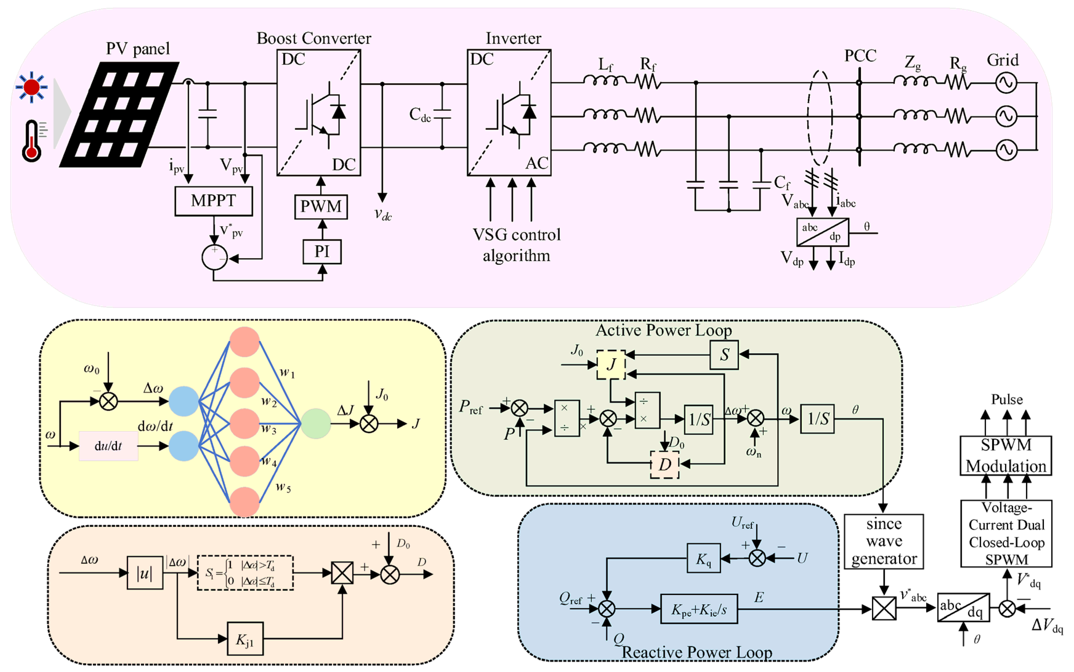
Figure 1 illustrates the schematic structure of a virtual synchronous generator. In terms of hardware configuration, the VSG shares a similar topology with conventional grid-connected inverters [15]. By referencing the electromagnetic and mechanical equations of traditional synchronous generators and integrating appropriate control strategies, the inverter can emulate the dynamic characteristics of a conventional synchronous machine [16].
The dynamics of the rotor motion for a virtual synchronous generator are governed by the equation presented in Equation (1). For analytical simplification, the synchronous generator is assumed to have a single pole pair, allowing its mechanical angular velocity to be regarded as equivalent to the electrical angular velocity [17].
J d ω d t = T m T e T d = T m T e D ( ω ω 0 ) d δ d t = ω
where J and D represent the virtual inertia and damping coefficient of the VSG, respectively; Tm, Te, and Td denote the mechanical torque, electromagnetic torque, and damping torque of the VSG; ω and ω0 are the angular frequency and nominal frequency of the VSG, respectively; and δ is the power angle of the VSG.
A synchronous generator regulates its active power output by adjusting the mechanical torque of its prime mover, thereby influencing the system frequency and contributing to frequency deviation correction and stabilization [18]. Inspired by this mechanism, the virtual synchronous generator formulates its active power control command Tm by combining a reference mechanical torque Tref with a frequency deviation feedback component ΔT, enabling effective regulation of the system’s active power output [19].
The mechanical torque and electromagnetic torque of the VSG are given by Equations (2) and (3), respectively:
T m = T ref + Δ T T ref = P ref ω Δ T = K ω ( ω ω 0 )
T e = P e ω = e a i a + e b i b + e c i c ω
where Tref and Pref denote the reference mechanical torque and reference power of the VSG, respectively; ΔT is the frequency deviation feedback signal; Kω is the frequency regulation coefficient; Pe represents the electromagnetic power; and eabc and iabc are the output voltage and current of the VSG in the abc reference frame.
By substituting Equation (2) into Equation (1) and performing linearization, the small-signal model can be expressed as follows:
Δ P ref Δ P out = J ω 0 d Δ ω m d t + ( D ω 0 + k ω ) Δ ω m

2.2. Effect of J and D on Frequency Response

Based on Equation (1), the influence of inertia and damping coefficients on the frequency response characteristics can be derived as follows:
Δ ω = T m T e J d ω / d t D d ω d t = T m T e T D J
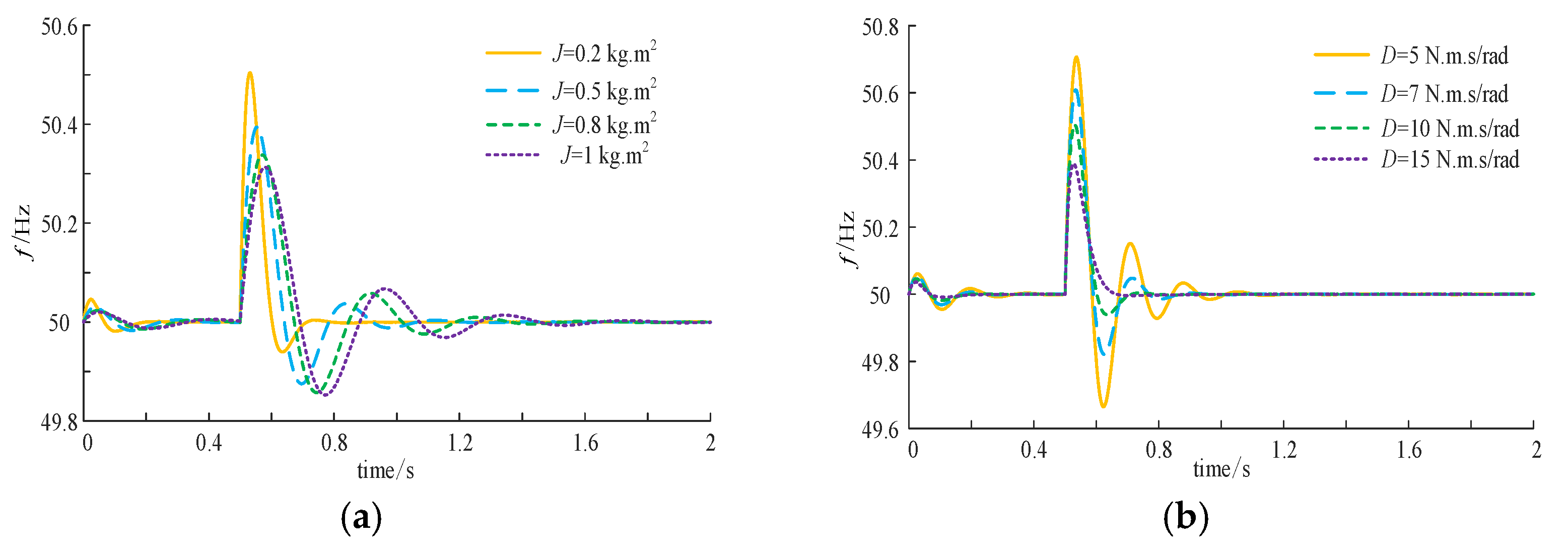
As shown in Equation (5), when TmTeJdω/dt remains constant, an increase in the damping coefficient D leads to a smaller frequency deviation. Conversely, when TmTeTd remains constant, a smaller inertia J results in a higher rate of change in frequency. The specific dynamic active power response under different inertia and damping settings is illustrated in Figure 2.

2.3. Impact of J and D on Active Power Response

Based on Equation (1), the transfer function between the input and output power of the VSG can be derived as follows:
G ( s ) = P ( s ) P n e f ( s ) = 1 J ω 0 E U Z s 2 + ( D J + K ω J ω 0 ) s + 1 J ω 0 E U Z
According to Equation (6), the corresponding natural angular frequency and damping ratio are given by:
ω n = E U J ω 0 Z ξ = D ω 0 Z 4 J E U + K ω Z 4 J ω 0 E U
As shown in Equation (7), when the inertia J remains constant, a larger damping coefficient D results in a smaller overshoot and a shorter settling time. Conversely, when the damping coefficient is fixed, increasing the inertia leads to a lower damping ratio, greater overshoot, and a longer settling time. The corresponding dynamic frequency responses under different J, D configurations are illustrated in Figure 3.
In summary, frequency and power oscillations can be effectively suppressed by adjusting the inertia coefficient J and damping coefficient D.

3. Adaptive Control Method for Virtual Inertia

3.1. Principle of Adaptive Inertia Control

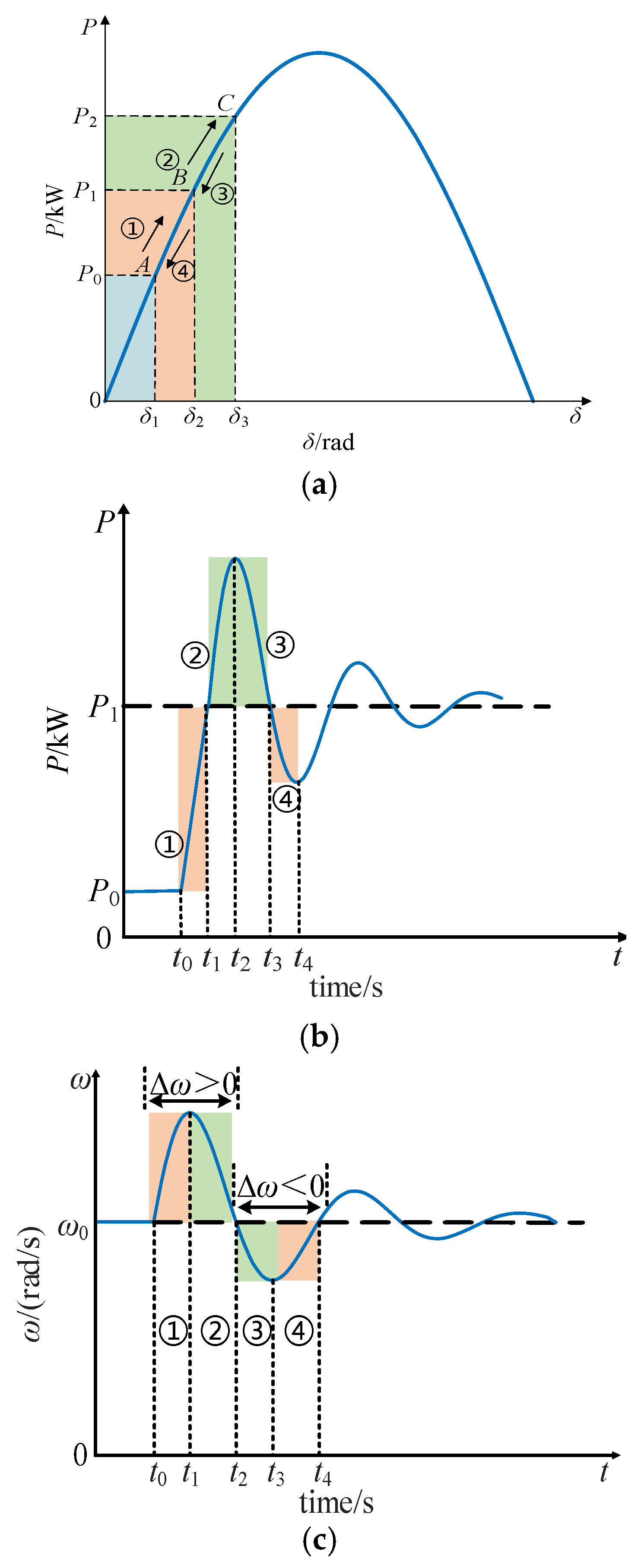
As shown in Figure 4a, the power–angle characteristic curve of the VSG is presented. Assuming that the system initially operates at a stable point A with a rated output power of P0, when the VSG reference power suddenly changes from P0 to P1, the system transitions from operating point A to a new steady-state point B after several cycles of damped oscillation.
During the transition process, both power and frequency exhibit damped oscillatory behavior [20]. For the purpose of stability analysis, the first oscillation cycle is selected and divided into four distinct stages. The following section provides a detailed analysis of each stage.
(1) The interval t0t1 is defined as Stage 1. During this stage, the reference power P1 of the VSG is greater than the actual output power, resulting in an increase in angular velocity. The angular velocity deviation is positive, and the rate of change in angular velocity gradually decreases but remains positive throughout the stage.
To mitigate the deviation in angular frequency and suppress the sharp rise in frequency ramp rate, the virtual inertia J should be adaptively increased. This helps slow down the deviation of angular velocity from its nominal value and improves the system’s transient performance.
(2) The interval t1t2 is defined as Stage 2. In this stage, the reference power P1 of the VSG is lower than the actual output power, causing the angular velocity to gradually decrease. However, the deviation remains positive, and the rate of change gradually increases but stays negative throughout the interval.
To accelerate the return of angular velocity to its nominal value, the virtual inertia J should be decreased adaptively, thereby enhancing the system’s ability to recover during this stage.
(3) The interval t2t3 is defined as Stage 3. During this stage, the power difference ΔP is negative, and the angular velocity ω deviates from the nominal value ω0 in the negative direction. To reduce both the rate of change in angular velocity and the angular velocity deviation, the virtual inertia J should be adaptively increased.
(4) The interval t3t4 is defined as Stage 4. In this stage, the power difference ΔP becomes positive, leading to an increase in angular velocity ω, which gradually approaches the nominal value ω0. To accelerate frequency recovery, the virtual inertia J should be adaptively decreased to increase the rate of change and simultaneously reduce the angular velocity deviation.
In the case of negative power variations, the method proposed in this paper is also capable of responding effectively. When the system encounters a negative power change, the virtual synchronous generator control strategy adjusts the virtual inertia and damping coefficients based on the direction of the power variation. The frequency change caused by negative power variation differs from that of positive power variations, mainly manifested as a slowdown in system frequency and a potential frequency drop. In this scenario, the coordinated adaptive control strategy proposed in this paper quickly reduces frequency fluctuations through adaptive adjustment of inertia and linear adjustment of damping, preventing large frequency deviations and thus ensuring the system’s stability.
Theoretical analysis shows that when the power variation is negative, the system first undergoes an increase in inertia, which enhances the system’s frequency recovery capability. Subsequently, the damping coefficient is dynamically adjusted based on the frequency change to reduce the amplitude of frequency oscillations. In particular, the increase in virtual inertia helps to suppress the rate of frequency decline, providing the system with sufficient recovery time and preventing a rapid drop in frequency.
Section 7 presents simulation results that further validate the effectiveness of the proposed control strategy under negative power variations. Similar to its performance under positive power variations, the system is able to maintain good frequency response and minimal frequency fluctuations, demonstrating the robustness and stability of the method under various disturbances.

3.2. Inertia Adaptive Adjustment Based on RBF Neural Network

In this study, a Radial Basis Function (RBF) neural network is selected as the core algorithm for adaptive virtual inertia regulation, primarily due to its advantages in real-time performance and structural simplicity. Compared with traditional feedforward neural networks such as the Back Propagation (BP) network, the RBF network utilizes locally responsive Gaussian kernel functions, offering faster training convergence and stronger nonlinear function approximation capabilities [21]. Furthermore, its fixed network structure and limited number of parameters make it suitable for embedding into practical digital controllers, enabling online learning and rapid response, which are essential for VSG systems sensitive to control delays [22].
In contrast, although deep neural networks (LSTM and CNN) excel in feature extraction and long-term dependency modeling, their complex architectures and high computational demands hinder real-time online implementation. Similarly, while fuzzy control and genetic algorithms offer a certain degree of adaptability, they lack sufficient nonlinear mapping capabilities and precision in dynamic tracking [23]. Therefore, the RBF neural network strikes a favorable balance between real-time performance and control accuracy, making it an appropriate choice for the inertia regulation module in the proposed coordinated control strategy [24].
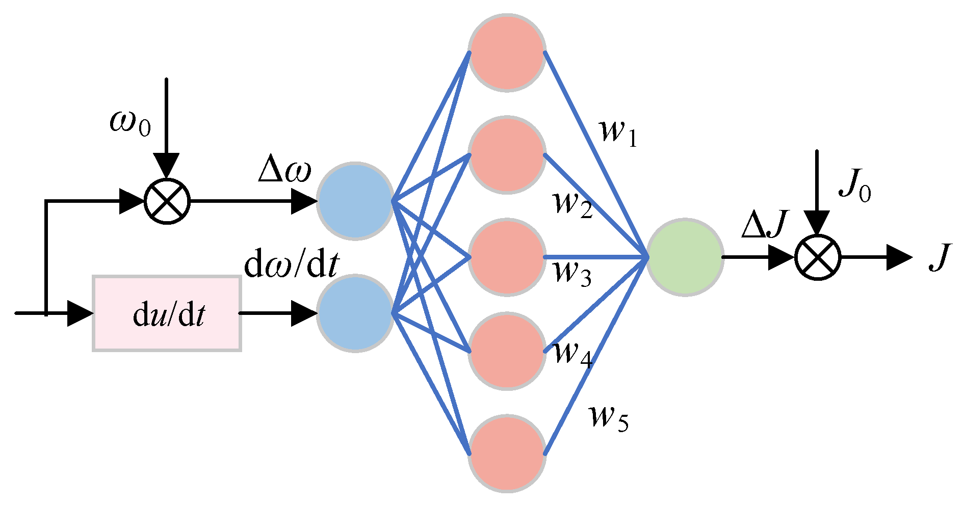
Figure 5 illustrates the structure of the RBF neural network integrated with VSG control.
The output function of the input layer of the neural network is given by:
O j ( 1 ) = x ( j ) , j = 1 , 2
where x(1) represents the angular frequency deviation, and x(2) denotes the rate of change in angular frequency.
The output function of the hidden layer of the neural network is defined as follows:
O i ( 2 ) ( k ) = g ( n e t i ( 2 ) ( k ) ) , i = 1 , 2 , , 5
where n e t i ( 2 ) and g ( ) represent the input to the hidden layer and the Gaussian function, respectively:
n e t i ( 2 ) = x , x = ( x ( 1 ) , x ( 2 ) ) g ( x ) = exp x c i 2 2 b i 2 , i = 1 , 2 , , 5
where bi is the width of the Gaussian function, and the width vector is defined as b = [ b 1 , , b 5 ] T , ci is the center vector of the ith hidden neuron, expressed as c i = [ c i 1 , c i 2 ] .
The input and output of the output layer of the neural network are given by:
n e t i ( 3 ) ( k ) = i = 1 5 w l i ( 3 ) O i ( 2 ) ( k ) Δ J = O l ( 3 ) ( k ) = f ( n e t l ( 3 ) ( k ) ) , l = 1
where wli(3) denotes the weight coefficient between the hidden layer and the output layer, and f(x) is the activation function of the output layer. In this study, the Sigmoid function is selected as the activation function.
The performance index function of the neural network is defined as follows:
E ( k ) = 1 2 ( ω 1 ( k ) ω 2 ( k ) ) 2
The weight coefficients wli(3), widths bi, and centers ci in the hidden layer are updated using the gradient descent method. The specific update formulas are as follows:
w l j ( k ) = w l j ( k 1 ) η E w l j ( t 1 ) + α [ w l j ( k 1 ) w l j ( k 2 ) ] b j i ( k ) = b j i ( k 1 ) η E b j i ( t 1 ) + α [ b j i ( k 1 ) b j i ( k 2 ) ] c j i ( k ) = c j i ( k 1 ) η E c j i ( t 1 ) + α [ c j i ( k 1 ) c j i ( k 2 ) ]
where the partial derivative E w l j ( t 1 ) is expressed as follows:
E w l j ( t 1 ) = E ( k ) ω ( k ) ω ( k ) J ( k ) J ( k ) net 1 ( 3 ) ( k ) net 1 ( 3 ) ( k ) w l j ( 3 ) ( k )
Since the calculation of ω J is complex, it is replaced by Δ ω Δ J . Meanwhile, the sign function sgn(x) is used to determine the direction of change, and the update is adjusted using a learning rate η to minimize the error introduced by the substitution.
ω J ω ( k ) ω ( k 1 ) J ( k ) J ( k 1 )
After the substitution, the weight update formula of the neural network is given by:
Δ w l i ( 3 ) ( k ) = η [ ω 0 ( k ) ω ( k ) ] sgn ω ( k ) ω ( k 1 ) J ( k ) J ( k 1 ) f net l ( 3 ) ( k ) O i ( 2 ) ( k ) + α Δ w l i ( 3 ) ( k 1 )

4. Analysis of Damping Adjustment Mechanisms and Adaptive Techniques

4.1. Analysis of the Damping Adjustment Mechanism

Similarly to Figure 2, for the purpose of stability analysis, the first oscillation cycle is selected and divided into four stages [24]. Each stage is analyzed in detail as follows:
(1)
The interval t0t1 is defined as Stage 1. During this stage, the reference power of the VSG is greater than the actual output power, resulting in an increase in angular velocity. To suppress the frequency deviation and mitigate the sudden rise in the frequency ramp rate, the damping coefficient should be adaptively increased, thereby slowing down the deviation of angular velocity from its nominal value.
(2)
The interval t1t2 is defined as Stage 2. In this stage, the reference power of the VSG is lower than the actual output power, causing the angular velocity to gradually decrease. However, the angular velocity deviation remains positive. To reduce this deviation, the damping coefficient should be adaptively increased.
(3)
The interval t2t3 is defined as Stage 3. During this stage, the power difference ΔP is negative, and the angular frequency deviates from its nominal value in the negative direction. To suppress the rate of change in angular velocity and reduce the deviation, the damping coefficient should be adaptively increased.
(4)
The interval t3t4 is defined as Stage 4. In this stage, the power difference ΔP becomes positive, leading to an increase in angular velocity, which gradually approaches its nominal value. At this point, the damping coefficient should be appropriately increased to reduce the angular frequency deviation and enhance the frequency ramp rate, thereby accelerating the restoration of angular frequency to its nominal value.

4.2. Adaptive Adjustment Method for the Damping Coefficient

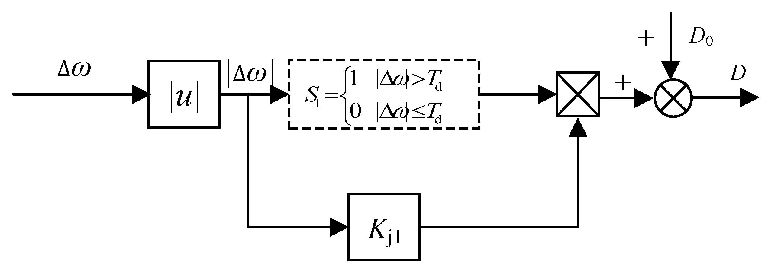
According to the analysis, the damping coefficient D should be appropriately increased in all four stages to suppress angular frequency fluctuations. To avoid excessive oscillation caused by frequent adjustments of the damping coefficient, a fluctuation threshold Td is introduced. The damping coefficient is updated only when the angular frequency deviation exceeds this threshold. In such cases, a damping increment linearly related to the magnitude of angular velocity variation is added. The specific expression is given by:
D = D 0 Δ ω T d D 0 + K d Δ ω Δ ω > T d
where D0 is the damping coefficient of the VSG under stable operating conditions, Kd is the damping regulation coefficient, and Td is the fluctuation threshold. The specific control strategy is illustrated in Figure 6.

5. Coordinated Adaptive Adjustment Method for Inertia and Damping

5.1. Overall Control Block Diagram and Control Algorithm Flowchart

The inertia adaptive control strategy primarily functions by dynamically adjusting the virtual inertia of the VSG in real time to accommodate frequency variations caused by system disturbances. Its main advantage lies in effectively suppressing the rate of change in frequency, thereby enhancing the system’s resistance to sudden disturbances in the early stages. However, since this strategy only regulates inertia without accounting for changes in damping, significant frequency overshoot and oscillations may still occur when frequency deviations are large, which limits the overall stability of the system.
The damping adaptive control strategy, on the other hand, dynamically adjusts the damping coefficient based on the magnitude of the frequency deviation, thereby reducing steady-state frequency deviation. This method can significantly mitigate frequency overshoot and improve steady-state accuracy. However, its capability to suppress ROCOF is limited, and its response speed is generally slower than inertia-based control, especially under large disturbances.
To overcome the limitations of the aforementioned single-parameter adaptation and leverage their complementary advantages, this paper proposes a novel Coordinated Adaptive Adjustment Method for Inertia and Damping. The core idea of this strategy is “division of labor and cooperation”: within a unified framework, the adaptive regulation of inertia and damping performs its specific duties while working in concert to achieve optimal control over the entire dynamic process.
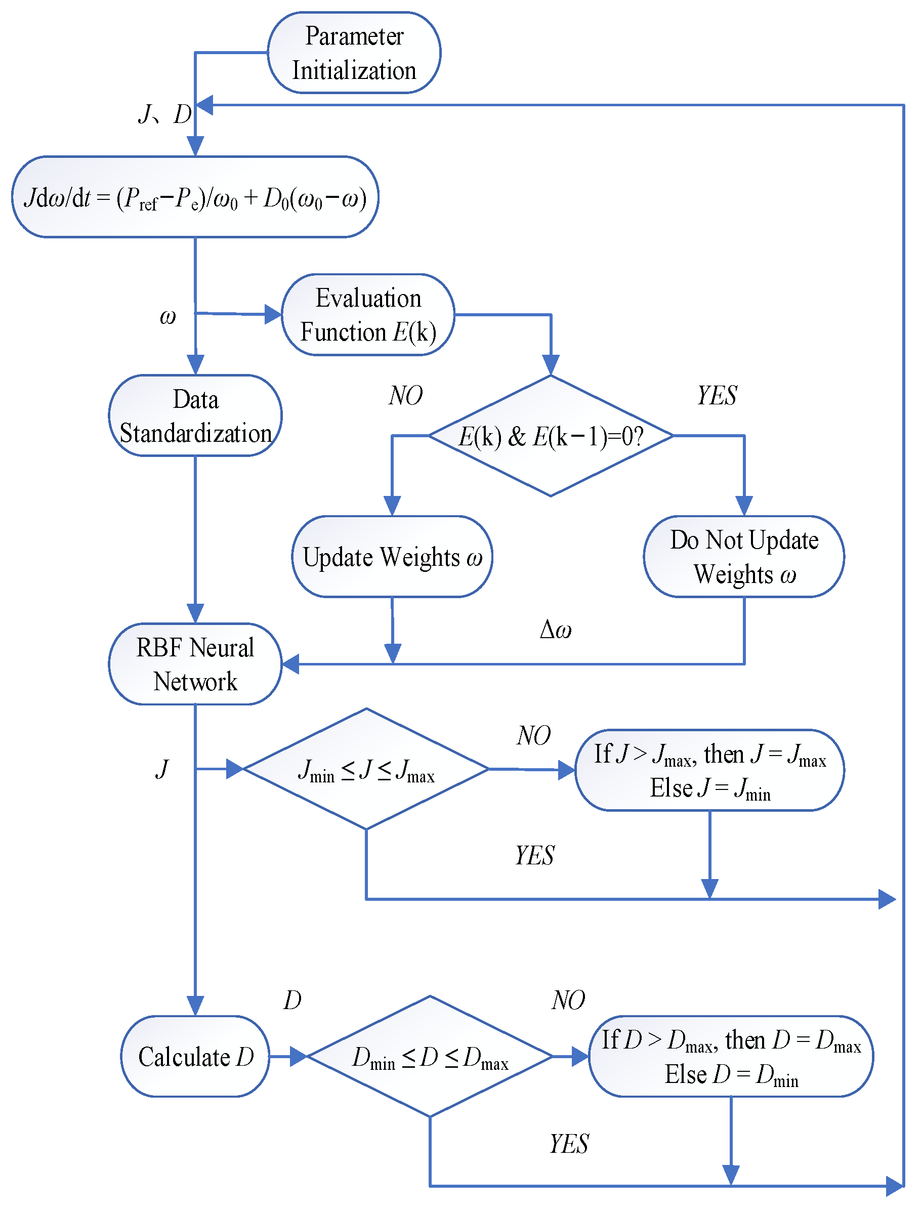
Specifically, the implementation process of this coordinated strategy is as follows:
(1)
Real-time state sensing: In each control cycle, the controller continuously monitors the system’s frequency deviation (Δω) and its rate of change (dω/dt). These two signals, which best reflect the system’s dynamic characteristics, serve as the inputs for the coordinated adjustment.
(2)
Intelligent inertia regulation: The signals Δω and dω/dt are fed into the RBF neural network. Leveraging its powerful nonlinear mapping capability, the network intelligently calculates the optimal virtual inertia J for the current moment. This part is primarily responsible for the “fast response,” i.e., strongly suppressing the rate of change in frequency by increasing inertia during the initial phase of a disturbance.
(3)
Precise damping compensation: Simultaneously, the controller calculates a damping increment ΔD using a simple linear algorithm based on the magnitude of the frequency deviation Δω. This part is mainly in charge of “stable suppression,” i.e., providing just-right damping throughout the oscillation process to effectively mitigate frequency overshoot and accelerate the system’s return to stability.
(4)
Coordinated output: Finally, the adaptively adjusted inertia J and damping D are simultaneously applied to the VSG’s swing equation, jointly determining the system’s dynamics for the next time step.
The overall control block diagram and the detailed algorithm flowchart for this method are presented in Figure 7 and Figure 8, respectively. Through this design, the proposed coordinated strategy achieves a comprehensive improvement in the speed, accuracy, and stability of the system’s dynamic response without significantly increasing computational complexity.
The control strategy is implemented in a detailed switching model of a three-phase voltage source inverter. The reference voltage generated by the VSG controller is modulated using Space Vector Pulse-Width Modulation (SVPWM) with a switching frequency of 10 kHz to generate the gating signals for the IGBTs.

5.2. Discussion on Computational Complexity and Real-Time Implementation

In the proposed coordinated adaptive control strategy based on the RBF neural network, the computational complexity is higher compared to that of traditional control methods, primarily due to the forward propagation and parameter update processes of the RBF neural network. Specifically, the computational load of the RBF neural network is mainly determined by the distance calculations between the input data and the hidden layer neurons, the activation function operations, and the weighted summation in the output layer. However, considering the application scenarios and the availability of computational resources, this increase in computational complexity is acceptable.
(1)
Computational load of RBF network forward propagation: In each forward propagation, the system inputs (Δω, dω/dt) are used to calculate the Euclidean distance between the input data and the center vectors of the h neurons in the hidden layer, followed by processing through the Gaussian activation function. The computational load of this process is proportional to the number of neurons, h, and is fixed and predictable. Therefore, even in larger systems, the computational load of forward propagation remains controllable.
(2)
Online update of RBF network parameters (gradient descent): The computational load during the gradient descent process is proportional to the number of hidden layer neurons, h, and the input dimension. Compared to traditional control methods, the computational load of this process is slightly higher; however, it does not significantly impact real-time performance.
(3)
Adaptive damping calculation: the calculation of adaptive damping involves only one absolute value calculation, one multiplication, and one addition, making its computational load negligible.
Although the RBF neural network introduces additional computational burden, this method still demonstrates good real-time implementation capability. Power electronic converters typically use high-performance digital signal processors (DSPs) or field-programmable gate arrays (FPGAs), which can perform calculations at high frequencies, ensuring that all computations are completed within the 50–100 microsecond control cycle. Therefore, the proposed control strategy is computationally feasible on existing hardware platforms.
Compared to traditional fixed-parameter PI or droop control methods, the proposed approach does indeed increase the computational load. However, this moderate increase in computation is justified by the improvement in dynamic performance and robustness. In comparison to “lightweight” intelligent control methods (such as fuzzy logic control), the computational load of the RBF network is comparable, and both are suitable for real-time control. In contrast, the computational demand of the proposed method is significantly lower than that of “heavyweight” intelligent control methods (such as deep learning and reinforcement learning), making it highly suitable for power electronics control.

6. Parameter Tuning and System Stability Analysis

6.1. Parameter Tuning for Kd and Td

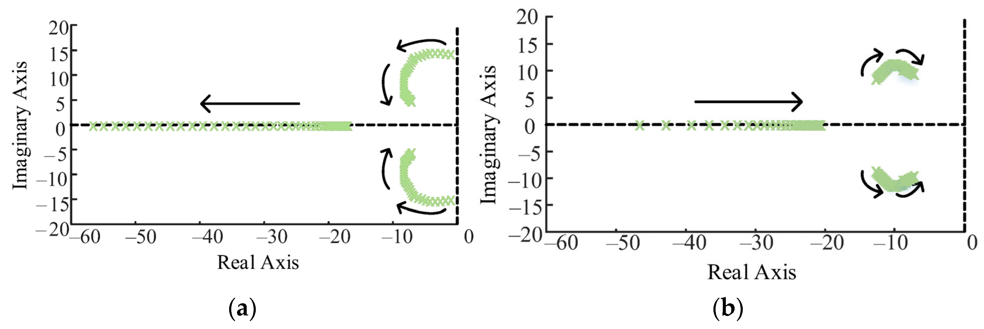
From Figure 9a, it can be observed that as Kd increases from 5 to 50, the distance between the dominant pole and the real axis increases, leading to a rise in oscillation frequency, a decrease in response time, and consequently an increase in the system’s response speed. Specifically, when Kd increases to 20 and continues to grow, the movement of the dominant pole becomes minimal. From the movement trend, it is evident that the dominant pole starts to move slightly towards the imaginary axis, and the system’s stability slightly decreases. Therefore, the value of Kd should not be too large, as larger values exhibit lower sensitivity to control performance. In conclusion, a moderate increase in Kd can improve both the system’s response speed and its stability.
From Figure 9b, it can be observed that as Td increases, the dominant pole of the system moves closer to the imaginary axis, which weakens the system’s stability. At the same time, the pole moves further away from the real axis, resulting in an increased system response speed. As Td continues to increase, the dominant pole moves towards both the imaginary and real axes, but the overall displacement is small, with minimal impact on the system’s stability. Therefore, Td should be chosen to have a relatively small value to maintain system stability.

6.2. System Stability Analysis

To analyze the stability of the virtual synchronous generator (VSG) controlled system, the Lyapunov direct method is used. First, the system’s state variables are defined as the angular velocity deviation x 1 = ω ω 0 and the angular acceleration x 2 = x ˙ 1 = ω ˙ . The system’s state equation is as follows:
x ˙ 1 = x 2
x ˙ 2 = 1 J ( P m P e D x 1 )
The Lyapunov function is chosen as V ( x 1 , x 2 ) = 1 2 ( x 1 2 + x 2 2 ) , which is zero at the equilibrium point (x1 = 0, x2 = 0) and is definitely positive. Calculating the derivative of the Lyapunov function, we obtain:
V ˙ ( x 1 , x 2 ) = x 1 x 2 + x 2 J ( P m P e D x 1 )
To ensure the system’s stability, it is necessary to prove that V ˙ ( x 1 , x 2 ) is negative definite. Through further simplification, we obtain:
V ˙ ( x 1 , x 2 ) = D x 1 2 1 J P e x 2 2
It can be seen that, since D > 0 and J > 0, the derivative of the Lyapunov function V ˙ ( x 1 , x 2 ) is negative, which proves that the system is asymptotically stable at the equilibrium point.

7. Simulation and Results Analysis

To validate the effectiveness of the proposed coordinated adaptive control strategy and assess its reliability, a simulation model was built on the MATLAB/Simulink platform, using version R2021a. We conducted 50 Monte Carlo simulations, introducing a ±5% random variation in the magnitude of load disturbances for each simulation to evaluate the performance of different control strategies under uncertain conditions. The parameters used in the simulation are listed in Table 2.

7.1. Validation of the Control Strategy Effectiveness Under Active Power Reference Variation

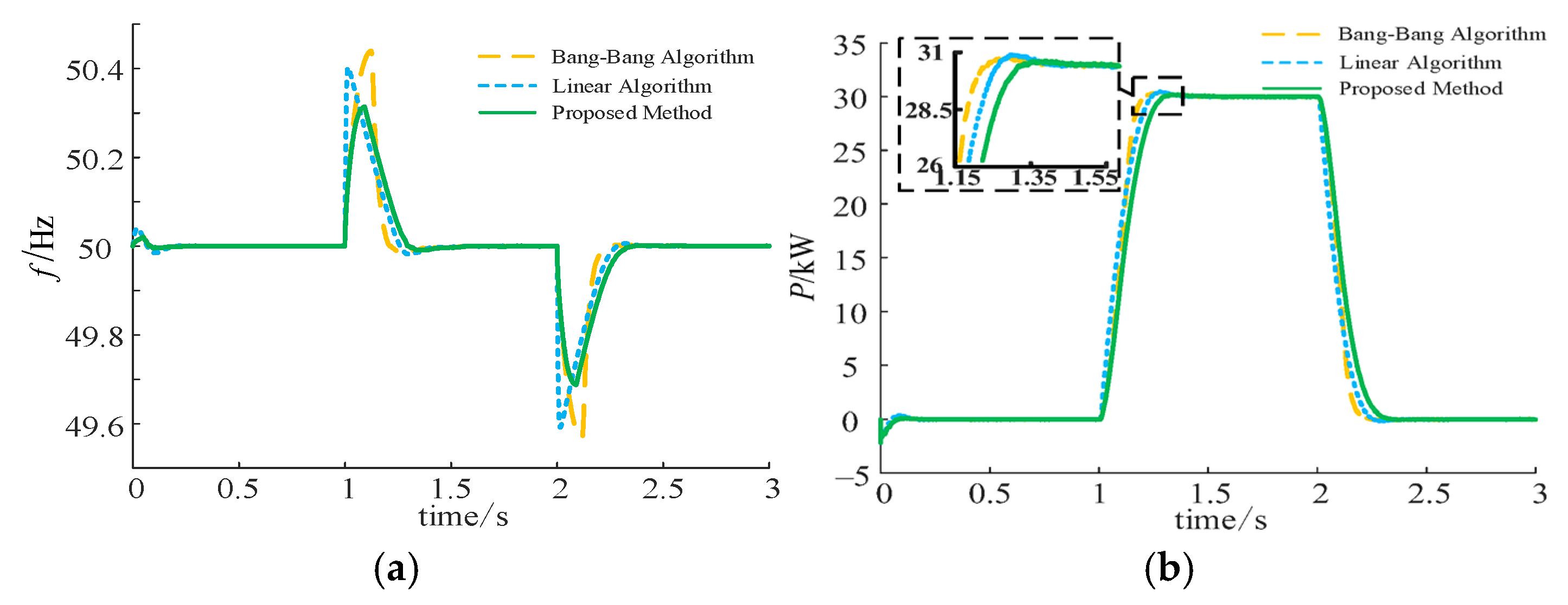
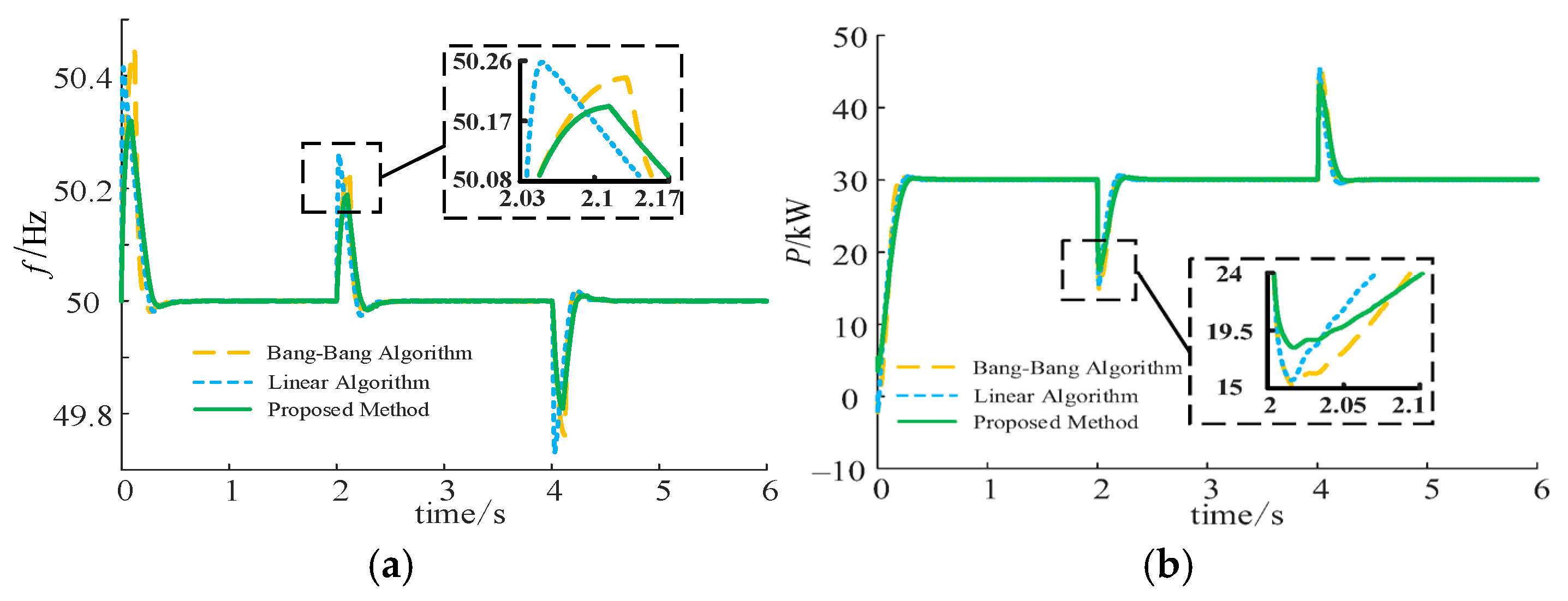
To further evaluate the robustness of the proposed control strategy under active power reference variations, the simulation scenario is set as follows: at t = 1 s, the active power reference value steps from 0 kW to 30 kW; at t = 2 s, it steps back down from 30 kW to 0 kW. The response curves presented below represent typical single-run results, while the key performance indicators are the statistical mean ± standard deviation from 50 simulation runs.
From the typical response curves shown in Figure 10 and the statistical results in Table 3, it can be observed that under the active power increase disturbance, the Bang–bang control method has a frequency minimum value of 49.59 ± 0.05 Hz and a power peak value of 30.32 ± 0.12 kW. The relatively large standard deviations indicate that this method is highly sensitive to disturbance variations, with poor performance consistency. The linear control method shows a frequency minimum value of 49.69 ± 0.04 Hz and a power peak value of 30.48 ± 0.15 kW. In contrast, the proposed method in this paper demonstrates outstanding performance and robustness, with a frequency minimum value of 49.88 ± 0.015 Hz and a power peak value of 30.18 ± 0.04 kW.
In terms of frequency control, compared to the Bang–bang control method, the proposed method reduces the average maximum frequency deviation by approximately 70.6%, and its frequency fluctuation standard deviation is only 30% of that of the former, demonstrating exceptionally high stability. In terms of power control, compared to the linear control method with the largest overshoot, the proposed method reduces the average power overshoot by about 62.8%, and its power fluctuation standard deviation is only 27% of the latter, indicating highly consistent and reliable output. Similar performance advantages were observed in the power decrease disturbance, where the proposed method significantly outperforms the other two methods in terms of frequency overshoot and recovery process.
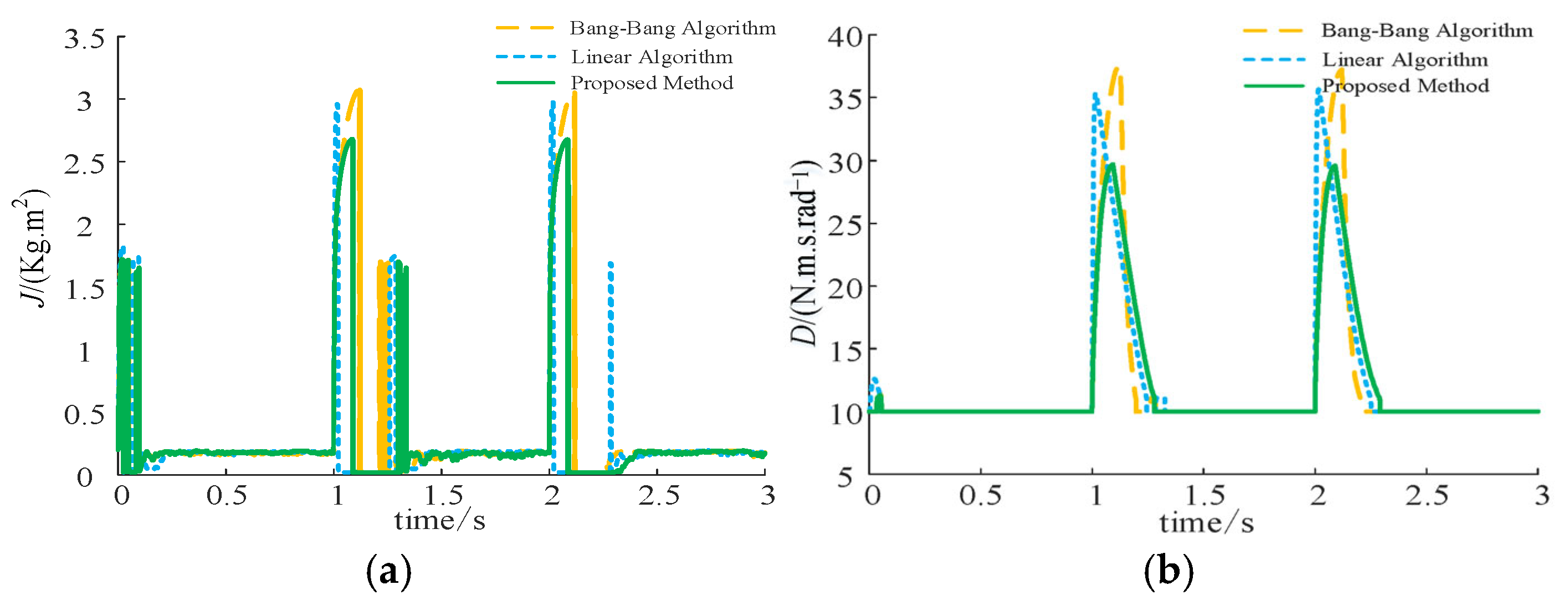
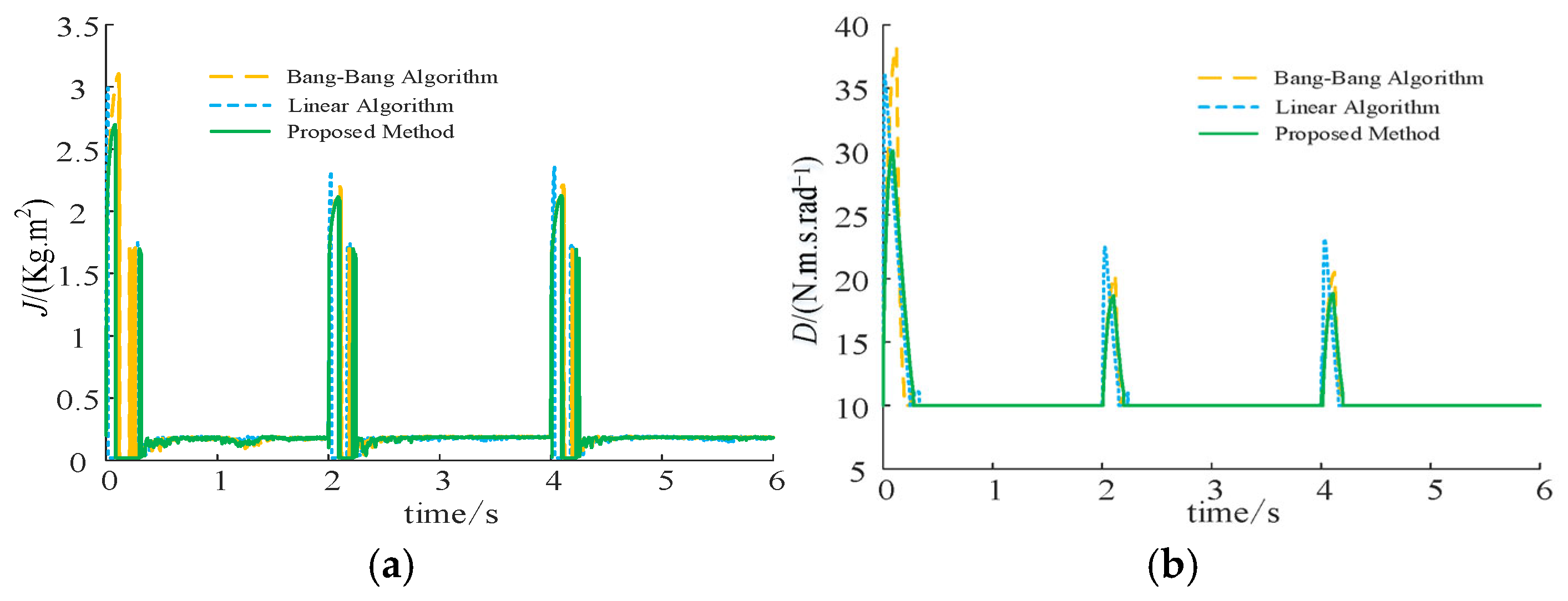
Figure 11 illustrates the dynamic adaptive process of virtual inertia and virtual damping under different control strategies during a power step disturbance. It can be clearly observed from the figure that, at the disturbance moments of t = 1 s and t = 2 s, all three methods respond quickly by instantaneously increasing virtual inertia J and virtual damping D to enhance the system’s disturbance rejection capability. However, there are significant differences in the adjustment behaviors of the strategies. The proposed coordinated adaptive method demonstrates higher efficiency and stability in parameter adjustment. Specifically, during the disturbance, the peak values of inertia and damping adjustment in the proposed method are lower compared to the other two methods’, indicating that the proposed method achieves a better system response with a lower control cost.
More importantly, the parameter adjustment curves of the proposed method are smoother, with no sharp peaks or sustained oscillations, and the system can quickly and stably recover to its initial values after the disturbance. This is attributed to the precise prediction of system dynamics by the RBF neural network and the optimization of the coordinated control framework, which achieves “just right” adjustment of inertia and damping. In contrast, the other two methods exhibit higher peak values and some oscillations during the adjustment process, which may lead to unnecessary energy consumption or introduce new system instability. Therefore, the simulation results strongly demonstrate the accuracy, efficiency, and robustness of the proposed method in parameter adaptive adjustment.

7.2. Validation of the Control Strategy Effectiveness Under Load Step Change

To further evaluate the robustness of the proposed control strategy under load conditions, this section sets up a load disturbance simulation scenario. A 15 kW load step-down is applied at t = 2 s, followed by a 15 kW load recovery at t = 4 s. The system’s dynamic response is shown in Figure 12.
Under the load step-down disturbance at t = 2 s, the system frequency exhibits significant overshoot. As shown in Figure 12a, the frequency peak values for the Bang–bang control and linear control are 50.24 Hz and 50.26 Hz, respectively, while the frequency peak for the proposed method is effectively suppressed to 50.19 Hz. Compared to the worst-performing linear control, the proposed method reduces the maximum frequency overshoot by approximately 26.9%. In terms of power response, the proposed method is able to decrease the output power from 30 kW to 15 kW the fastest and most smoothly, with the smallest power dip, reaching only about 18.50 kW. In contrast, the other two methods experience a deeper power drop, with the lowest point approaching 14.50 kW, and their recovery process is accompanied by larger oscillations.
Under the load step-increase disturbance at t = 4 s, the system frequency experiences a dip. The proposed method once again demonstrates its superiority, with both a smaller frequency drop and faster recovery time compared to the other two control methods. In terms of power response, the proposed method restores the power from 15 kW to 30 kW at the fastest speed with minimal overshoot. Considering the two opposite disturbance scenarios, the simulation results thoroughly demonstrate that the proposed coordinated adaptive control strategy exhibits outstanding dynamic performance in handling bidirectional load fluctuations. It effectively suppresses both frequency and power fluctuations, showing strong robustness. As shown in Table 4, a performance comparison is provided to validate the effectiveness of the control strategy under the load step change scenario.
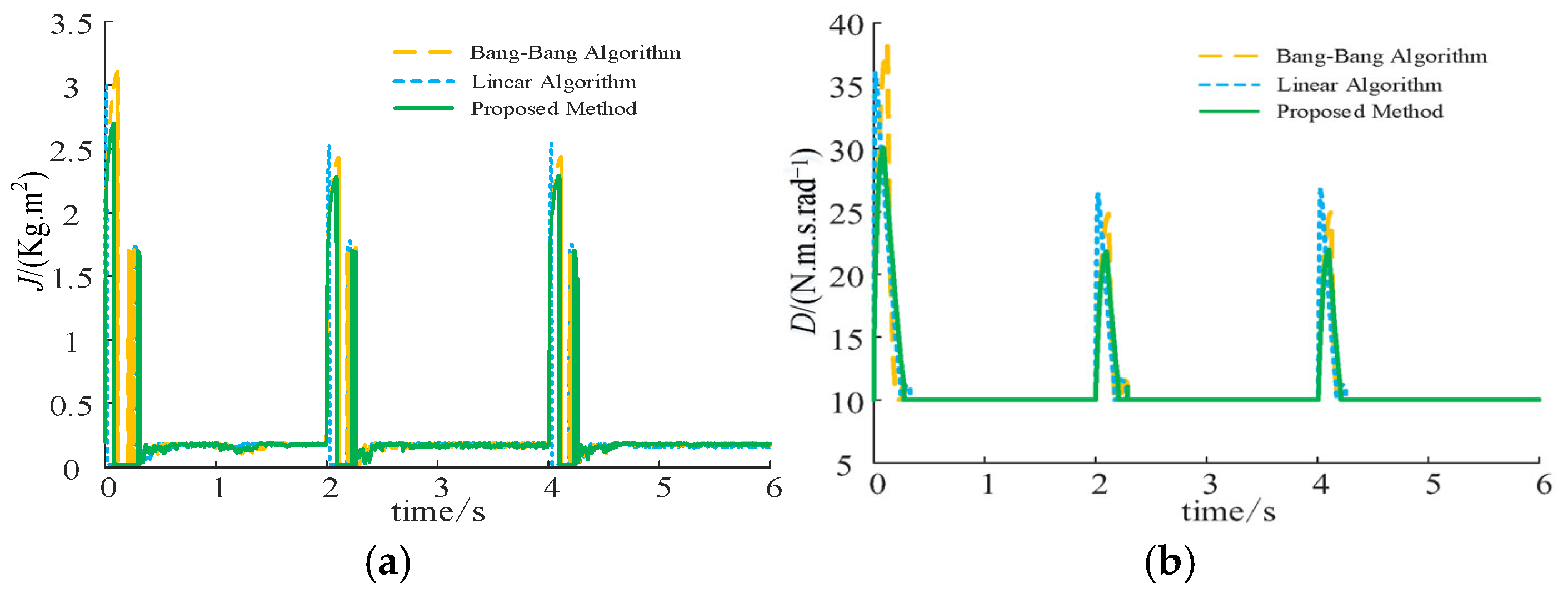
Figure 13 illustrates the dynamic response of virtual inertia and virtual damping under different control strategies during load disturbances. At the moments of load step-down at t = 2 s and load step-increase at t = 4 s, all three methods quickly adjust the values of J and D to respond to the changes in the system’s state. However, the proposed coordinated adaptive method once again demonstrates its precision and smoothness in parameter adjustment.
Specifically, during both disturbances, the peak values of J and D adjustments in the proposed method are significantly lower than those of the other two methods. Furthermore, the adjustment curves do not exhibit excessive peaks or oscillations. This indicates that the proposed method provides “just-right” inertia and damping support based on the system’s true dynamic needs, thereby avoiding the potential instability that may arise from over-adjusting parameters. This efficient and stable parameter adjustment mechanism is the fundamental reason why the proposed method achieves optimal control performance under various operating conditions.

7.3. Validation of the Control Strategy Effectiveness Under Combined Disturbance Variation

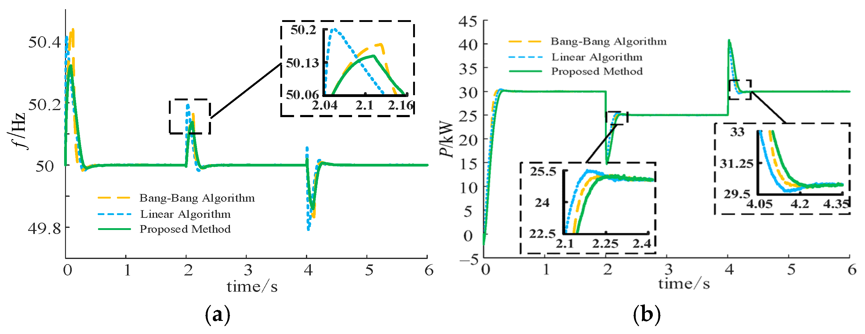
To comprehensively assess the robustness of the proposed strategy under complex operating conditions, multiple disturbance simulation scenarios are designed in this section. The system initially operates with a 30 kW load. At t = 2 s, the power reference value is reduced from 30 kW to 25 kW, while the external load decreases by 15 kW. At t = 4 s, both the reference value and the load are restored to their initial states.
The differences in the system’s dynamic response are particularly evident under the composite disturbance at t = 2 s. As shown in Figure 14a, due to the instantaneous increase in net power injection, the system frequency experiences an overshoot. The linear control method exhibits the highest frequency peak, reaching 50.19 Hz; the Bang–bang control method performs second, with a peak of 50.16 Hz; while the proposed method successfully suppresses the frequency peak to 50.13 Hz. Compared to linear control, the proposed method reduces the frequency overshoot by approximately 31.8%, demonstrating excellent frequency stability. In terms of power response, the proposed method tracks the new power reference value of 25 kW the fastest and most smoothly, while the other two methods exhibit longer adjustment times and greater fluctuations.
During the disturbance recovery phase at t = 4 s, the system is required to simultaneously handle both the increase in the reference value and the load, which causes a downward impact on the frequency. The proposed method once again performs the best, with its frequency minimum (49.86 Hz) being significantly higher than the other two methods (49.79 Hz), reducing the maximum frequency deviation by approximately 23.8%. Additionally, the proposed method demonstrates the fastest and most stable power response with the smallest overshoot. Based on its comprehensive performance under multiple disturbances, it can be concluded that the proposed coordinated adaptive control strategy not only outperforms in single-disturbance scenarios but also maintains strong dynamic tracking and disturbance rejection capabilities in more realistic, complex, and composite-disturbance conditions, fully validating its robustness. As shown in Table 5, a performance comparison is presented to validate the effectiveness of the control strategy under combined disturbance variation.
Figure 15 illustrates the dynamic response of virtual inertia and virtual damping under different control strategies in a complex multi-disturbance scenario. At the moments of composite disturbances at t = 2 s and t = 4 s, all three methods quickly adaptively adjust J and D.
The analysis results further highlight the superiority of the proposed method. During both disturbances, the J and D adjustment curves in the proposed method exhibit moderate peak values, smooth shapes, and no significant secondary oscillations. For instance, at t = 2 s, the inertia peak is approximately 2.2 and the damping peak is about 21, both significantly lower than those of the other two methods. This indicates that, in the complex scenario where both the reference value and external load change simultaneously, the proposed coordinated control framework can more accurately assess the inertia and damping support required by the system, avoiding parameter fluctuations caused by excessive or improper adjustments. This stable and efficient parameter adaptation capability is the core guarantee for ensuring the system maintains excellent dynamic performance under multiple disturbances.

8. Conclusions

To address the dynamic stability challenges faced by grid-forming inverters in low-inertia power systems, this paper proposes and validates an innovative coordinated adaptive control strategy for virtual inertia and damping. The core objective of this study is to overcome the limitations of traditional single-parameter regulation and achieve synchronized and efficient suppression of system frequency and power fluctuations. The main conclusions and contributions are as follows:
(1)
Revealing the inherent coordinated mechanism of inertia–damping control: This paper confirms that virtual inertia primarily governs the system’s initial response to disturbances, while virtual damping plays a dominant role in suppressing oscillations and steady-state deviations. This study further reveals a coupled interaction between these two parameters during dynamic processes, and adjusting either parameter alone does not achieve optimal control. This provides a solid theoretical foundation for the coordinated regulation strategy.
(2)
Proposing a coordinated control framework that balances speed and stability: The proposed strategy optimizes the system’s dynamic response through decoupled control. Specifically, adaptive inertia regulation based on the RBF neural network intelligently manages the rate of change in frequency, while adaptive damping compensation, which is linearly related to frequency deviation, effectively suppresses overshoot. This coordinated mechanism allows the controller to perform optimally during different disturbance phases, ensuring stable system operation under various disturbance conditions.
(3)
Significant performance improvements validated through simulations: Under typical power step disturbances, the proposed strategy reduces the maximum frequency deviation by over 65% and active power overshoot by approximately 66.7%. Additionally, under load variation and composite disturbance conditions, frequency overshoot and power response are optimized by approximately 3.6% and 23.3%, respectively. These quantitative results demonstrate that the proposed coordinated control strategy offers significant advantages in enhancing system dynamic response, frequency stability, and power overshoot suppression.
In conclusion, the coordinated adaptive control strategy proposed in this paper, with its innovative coordinated mechanism and quantified superior performance, provides an efficient and practical solution that effectively enhances the stability and reliability of low-inertia power grids. Future research will focus on extending this strategy to multi-inverter systems and further exploring the impact of communication delays on the effectiveness of coordinated control.

Author Contributions

Conceptualization, B.M. and L.B.; data curation, H.Z.; formal analysis, X.C.; funding acquisition, B.M.; investigation, H.Z., X.C. and Y.C.; methodology, X.C., Y.C. and B.M.; project administration, B.M.; software, X.C. and Y.C.; supervision, B.M. and L.B.; validation, H.Z.; writing—original draft, H.Z. and X.C.; writing—review and editing, B.M., Y.C. and L.B. All authors have read and agreed to the published version of the manuscript.

Funding

This research is supported by “Science and Technology Project of Shanxi Electric Power Research Institute Co., Ltd. (SGSXDKOODJIS2400119)”.

Data Availability Statement

Data are contained within this article.

Conflicts of Interest

Authors Boyu Ma and Yang Cui were affiliated with the School of Electrical Engineering, Northeast Electric Power University. Author Xueting Cheng was affiliated with both State Grid Shanxi Electric Power Research Institute and the School of Electrical Engineering, Zhejiang University. Authors Huiping Zheng and Liming Bo were affiliated with State Grid Shanxi Electric Power Research Institute. The authors declare that this research was conducted in the absence of any commercial or financial relationships that could be construed as potential conflicts of interest.

Nomenclature

VariableDescription
G(s)Transfer function representing the relationship between system output and input.
P(s)System output signal.
Pref(s)Reference or target input signal for the system.
E, UInput to the system (e.g., voltage, power).
ω0Natural frequency of the system, related to its inherent oscillatory properties.
ZImpedance of the system, describing the relationship between current and voltage.
JMoment of inertia of the system, determining its resistance to rotational movement.
DDamping coefficient, affecting the system’s oscillatory behavior.
KGain constant, influencing the system response speed.
sComplex frequency variable used in system analysis.
VpvOutput voltage of the PV panel.
IpvCurrent from the PV panel.
VdcDC voltage in the system.
CdcDC voltage capacitor used for smoothing.
LrInductor in the inverter.
RrResistor in the inverter.
PCCPoint of Common Coupling, where the system connects to the grid.
ZrImpedance of the grid.
ΔωFrequency deviation between the system and the grid.
dω/dtRate of frequency change.
J0Equivalent moment of inertia for the system.
w1, w2, w3, w4, w5Neural network weights used for system control.
pActive power of the system.
ωAngular velocity of the system.
SImpedance of the system.
eError signal used for feedback control.
UfReactive power loop voltage.
KpProportional gain constant in the control loop.
KdDifferential gain constant in the control loop.
EControl error signal for adjustment.
SPWMSine wave pulse-width modulation for controlling inverter output.
ΔVudVoltage error signal used to adjust output voltage.
ΔgChange in current.
*Per unit value

References

  1. Grover, H.; Sharma, S.; Verma, A.; Singh, B.; Mishra, S. Adaptive parameter tuning strategy of VSG-based islanded microgrid under uncertainties. Electr. Power Syst. Res. 2024, 235, 1108–1119. [Google Scholar] [CrossRef]
  2. Lu, S.; Zhu, Y.; Dong, L.H.; Li, J.; Wang, L.; Wang, Z. Small-signal stability research of grid-connected virtual synchronous generators. Energies 2022, 15, 7158. [Google Scholar] [CrossRef]
  3. Guo, L.; Xu, Z.; Jin, N.; Wang, Y.; Chen, H.; Liu, Y. A weighted voltage model predictive control method for a virtual synchronous generator with enhanced parameter robustness. Prot. Control Mod. Power Syst. 2021, 6, 482–492. [Google Scholar] [CrossRef]
  4. Wang, Z.; Meng, F.; Zhang, Y.; Wang, W.; Li, G.; Ge, J. Cooperative Adaptive Control of Multi-Parameter Based on Dual-Parallel Virtual Synchronous Generators System. IEEE Trans. Energy Convers. 2023, 38, 2396–2408. [Google Scholar] [CrossRef]
  5. Hou, X.; Sun, Y.; Zhang, X.; Lu, J.; Wang, P.; Guerrero, J.M. Improvement of Frequency Regulation in VSG-Based AC Microgrid Via Adaptive Virtual Inertia. IEEE Trans. Power Electron. 2020, 35, 1589–1602. [Google Scholar] [CrossRef]
  6. Karimi, A.; Khayat, Y.; Naderi, M.; Dragičević, T.; Mirzaei, R.; Blaabjerg, F.; Bevrani, H. Inertia response improvement in AC microgrids: A fuzzy-based virtual synchronous generator control. IEEE Trans. Power Electron. 2020, 35, 4321–4331. [Google Scholar] [CrossRef]
  7. Wang, Y.; Wai, R. Adaptive fuzzy-neural-network power decoupling strategy for virtual synchronous generator in micro-grid. IEEE Trans. Power Electron. 2022, 37, 3878–3891. [Google Scholar] [CrossRef]
  8. Chen, Y.; Hesse, R.; Turschner, D.; Beck, H.-P. Improving the grid power quality using virtual synchronous machines. In Proceedings of the 2011 IEEE 8th International Conference on Power Electronics and ECCE Asia (ICPE & ECCE), Jeju, Republic of Korea, 30 May–3 June 2011; pp. 1058–1065. [Google Scholar]
  9. Liu, C.; Li, B.; Zhang, Y.; Jiang, Q.; Liu, T. The LCC type DC grids forming method and fault ride-through strategy based on fault current limiters. Int. J. Electr. Power Energy Syst. 2025, 170, 110843. [Google Scholar] [CrossRef]
  10. Alipour, J.; Miura, Y.; Ise, T. Power system stabilization using virtual synchronous generator with alternating moment of inertia. IEEE J. Emerg. Sel. Top. Power Electron. 2015, 3, 451–458. [Google Scholar] [CrossRef]
  11. Zhao, H.; Dong, Y.; Sun, K. Data-driven virtual inertia control based on neural networks for microgrid frequency stability. Appl. Energy 2020, 275, 115353. [Google Scholar]
  12. Xiong, R.; Ma, Y.; He, H. An improved neural-network-based adaptive control method for grid-connected inverters in low-inertia power systems. Energy Rep. 2021, 7, 6452–6460. [Google Scholar]
  13. Liu, J.; Liu, X.; Liu, J.; Li, X.; Wang, J. Adaptive-Droop-Coefficient VSG Control for Cost-Efficient Grid Frequency Support. IEEE Trans. Power Syst. 2024, 39, 6768–6771. [Google Scholar] [CrossRef]
  14. Jain, A.; Pathak, M.K.; Padhy, N.P. Modified VSG Control for Enhancing Its Numerical Stability and Reducing the Impact on ULFO of System. IEEE Trans. Power Syst. 2025, 40, 1320–1334. [Google Scholar] [CrossRef]
  15. Utkarsha, P.; Naidu, N.K.S.; Sivaprasad, B.; Singh, K.A. A Flexible Virtual Inertia and Damping Control Strategy for Virtual Synchronous Generator for Effective Utilization of Energy Storage. IEEE Access 2023, 11, 124068–124080. [Google Scholar] [CrossRef]
  16. Li, L.; Zhou, K.; Tian, P. A Decentralized Control with Adaptive Virtual Inertia and Damping Combination for Islanded Cascaded-Type VSG Systems. IEEE Access 2023, 11, 139272–139283. [Google Scholar] [CrossRef]
  17. Li, C.; Yang, Y.; Cao, Y.; Aleshina, A.; Xu, J.; Blaabjerg, F. Grid Inertia and Damping Support Enabled by Proposed Virtual Inductance Control for Grid-Forming Virtual Synchronous Generator. IEEE Trans. Power Electron. 2023, 38, 294–303. [Google Scholar] [CrossRef]
  18. Jiang, K.; Su, H.; Lin, H.; He, K.; Zeng, H.; Che, Y. A Practical Secondary Frequency Control Strategy for Virtual Synchronous Generator. IEEE Trans. Smart Grid 2020, 11, 2734–2736. [Google Scholar] [CrossRef]
  19. Chen, S.; Sun, Y.; Han, H.; Shi, G.; Guan, Y.; Guerrero, J.M. Dynamic Frequency Performance Analysis and Improvement for Parallel VSG Systems Considering Virtual Inertia and Damping Coefficient. IEEE J. Emerg. Sel. Top. Power Electron. 2023, 11, 478–489. [Google Scholar] [CrossRef]
  20. Tao, L.; Zha, X.; Tian, Z.; Sun, J. Optimal Virtual Inertia Design for VSG-Based Motor Starting Systems to Improve Motor Loading Capacity. IEEE Trans. Energy Convers. 2022, 37, 1726–1738. [Google Scholar] [CrossRef]
  21. Wang, Z.; Chen, Y.; Li, X.; Xu, Y.; Luo, C.; Li, Q. Active Power Oscillation Suppression Based on Decentralized Transient Damping Control for Parallel Virtual Synchronous Generators. IEEE Trans. Smart Grid 2023, 14, 2582–2592. [Google Scholar] [CrossRef]
  22. Fu, S.; Sun, Y.; Li, L.; Liu, Z.; Han, H.; Su, M. Power Oscillation Suppression of Multi-VSG Grid via Decentralized Mutual Damping Control. IEEE Trans. Ind. Electron. 2022, 69, 10202–10214. [Google Scholar] [CrossRef]
  23. Rathnayake, D.B.; Me, S.P.; Razzaghi, R.; Bahrani, B. H∞-Based Control Design for Grid-Forming Inverters with Enhanced Damping and Virtual Inertia. IEEE J. Emerg. Sel. Top. Power Electron. 2023, 11, 2311–2325. [Google Scholar] [CrossRef]
  24. Xiong, X.; Li, X.; Luo, B.; Huang, M.; Zhao, C.; Blaabjerg, F. An Additional Damping Torque Method for Low-Frequency Stability Enhancement of Virtual Synchronous Generators. IEEE Trans. Power Electron. 2024, 39, 15858–15869. [Google Scholar] [CrossRef]
Figure 1. VSG system architecture.
Energies 18 04255 g001
Figure 2. Active power dynamics under varying inertia and damping: (a) fixed D, varying J; (b) fixed J, varying D.
Energies 18 04255 g002
Figure 3. Frequency dynamics under varying inertia and damping: (a) fixed D, varying J; (b) fixed J, varying D.
Energies 18 04255 g003
Figure 4. Dynamic regulation process of the VSG: (a) power–angle characteristic curve of the VSG; (b) active power oscillation curve; (c) angular frequency oscillation curve.
Energies 18 04255 g004
Figure 5. RBF neural network for VSG control.
Energies 18 04255 g005
Figure 6. Adaptive damping regulation architecture.
Energies 18 04255 g006
Figure 7. Coordinated adaptive control strategy for inertia and damping.
Energies 18 04255 g007
Figure 8. VSG control algorithm flowchart.
Energies 18 04255 g008
Figure 9. Pole trajectory analysis for parameter tuning of Kd and Td: (a) pole trajectory under Kd parameter tuning; (b) pole trajectory under Td parameter tuning.
Energies 18 04255 g009
Figure 10. Comparison of frequency and active power response for different adaptive methods under active power reference variation scenario: (a) comparison of frequency output responses; (b) comparison of active power output responses.
Energies 18 04255 g010
Figure 11. Comparison of inertia and damping values for different adaptive methods: (a) comparison of inertia values; (b) comparison of damping values.
Energies 18 04255 g011
Figure 12. Comparison of frequency and active power response for different adaptive methods under load step change scenario: (a) comparison of frequency output responses; (b) comparison of active power output responses.
Energies 18 04255 g012
Figure 13. Comparison of inertia and damping values for different adaptive methods: (a) comparison of inertia values; (b) comparison of damping values.
Energies 18 04255 g013
Figure 14. Comparison of frequency and active power response for different adaptive methods under combined disturbance variation scenario: (a) comparison of frequency output responses; (b) comparison of active power output responses.
Energies 18 04255 g014
Figure 15. Comparison of inertia and damping values for different adaptive methods: (a) comparison of inertia values; (b) comparison of damping values.
Energies 18 04255 g015
Table 1. Comparison of the proposed method with existing control strategies.
MethodInertia AdjustmentDamping AdjustmentComputational ComplexityReal-Time ApplicabilityAdjustment Accuracy
Fixed Parameters [6,7,8]××××
Single-Parameter
Adaptive Method [9]
×××
Neural-Network-Based
Adaptive Method [10,11,12,13]
××
Linear-Algorithm-Based
Adaptive Control [14,15]
×
Proposed Method
Table 2. Main control parameters of VSG and grid side.
ParameterValue
DC Voltage Udc/V800
Grid-Side Voltage U/V 380
Rated Frequency f/Hz50
Inverter-Side Inductance L1/mH 0.7
Grid-Side Inductance L2/mH 1.5
Capacitor C/μF1500
Rated Angular Frequency ω0/(rad·s−1)314
Table 3. Performance comparison for validation of control strategy effectiveness under active power reference variation.
Performance MetricBang–Bang Control Linear Control Proposed Method
Peak Frequency (Hz)49.5950.3149.88
Maximum Frequency Deviation (Hz)0.410.480.12
Peak Power (kW)30.3230.4830.18
Power Overload (%)1.071.60.6
Table 4. Performance comparison for validation of control strategy effectiveness under load step change scenario.
Performance MetricBang–Bang Control Linear Control Proposed Method
Peak Frequency (Hz)50.2450.2650.19
Maximum Frequency Deviation (Hz)0.240.260.19
Power Response (kW)14.51518.5
Table 5. Performance comparison for validation of control strategy effectiveness under combined disturbance variation.
Performance MetricBang–Bang ControlLinear ControlProposed Method
Peak Frequency (Hz)50.1650.250.13
Maximum Frequency Deviation (Hz)0.160.20.13
Power Response (kW)−14.5−15−18.5
Minimum Frequency (Hz)−49.83−49.79−49.86
Maximum Frequency Deviation (Hz)0.170.210.14
Power Response (kW)−14.5−15−18.5
Disclaimer/Publisher’s Note: The statements, opinions and data contained in all publications are solely those of the individual author(s) and contributor(s) and not of MDPI and/or the editor(s). MDPI and/or the editor(s) disclaim responsibility for any injury to people or property resulting from any ideas, methods, instructions or products referred to in the content.