Abstract
Chip-level cooling has become a thermal bottleneck in next-generation data centers. Although previous studies have optimized evaporator wick structures, they are limited to a single condensation path and ignore the combined effects of the loop heat pipe (LHP) orientation on the capillary wick (CW) replenishment and reflux subcooling. To bridge this gap, this study successfully designed an innovative flat-plate evaporator water-cooled LHP with a parallel condensation pipeline. Experiments were conducted with a 20 °C coolant and at a 4 L/min flow rate across nine orientations. The heat transfer characteristics of LHPs with parallel and series condensation pipelines were compared. The analysis focused on the relationship between the working fluid (WF) replenishment of the CW and the WF reflux temperature in the compensating chamber (CC). The experimental results demonstrated that the parallel condensation LHP could sustainably dissipate 750 W without thermal runaway. At this power, the minimum junction temperature of 82.34 °C was measured at orientation 2 (+60°). For low power and at the nine orientations, the series LHP generally had lower temperatures. However, when the power exceeded 600 W, the parallel LHP showed lower temperatures at orientations 1 (+90°), 2 (+60°), and 3 (+30°). At orientation 9, the parallel LHP had lower temperatures when the power surpassed 200 W. Theoretical analysis indicated that the orientation changes affected the heat transfer via the WF reflux temperature, reflux resistance, and CW replenishment rate. Furthermore, the LHP system we developed in this study is capable of fully satisfying the cooling requirements of data center server chips.
1. Introduction
In recent years, the explosive growth in the computing power demand, sparked by the swift progress of information technology, has driven a remarkable expansion of the data center infrastructure, which is pivotal for managing large-scale data processing and storage. However, this trend has also caused a significant rise in energy consumption and carbon emissions, creating a major challenge for environmental protection and sustainable development. Some studies have shown that in modern data centers, the cooling system consumes a large proportion of the total energy, roughly 38~40% of the total electricity used [1,2,3]. Most of this energy is released into the environment as heat during cooling. Data center cooling is complex and multifaceted, covering chip, cabinet, gate, and room heat dissipation. The data center thermal analysis is shown in Figure 1a. Notably, chip heat dissipation consumes significant energy. As chip manufacturing technology has advanced and performance improved, the chip heat flux density has risen significantly. Thus, chip heat dissipation is crucial for the thermal environment of the whole data center, directly impacting its operational efficiency and stability. The heat dissipation issue is growing more critical and has become a key factor impacting the operational efficiency and reliability of data centers [4].
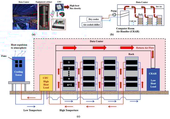
Figure 1.
(a) Data center thermal analysis. (b) Basic principles of conventional air-cooled technology. (c) Operating principle of data center energy-saving by applying LHP chip-level cooling.
Traditional air-cooling technology has long dominated the data center cooling sector, utilizing an air conditioning system that extracts heat from the equipment and distributes it throughout the room [5]. The basic principles of traditional air-cooled technology are shown in Figure 1b. However, with the ongoing expansion of data centers’ scale, the continuous increase in server density, and the significant rise in the chip heat flux density, traditional air-cooling systems are gradually revealing their limitations and struggling to meet the cooling demands of modern data centers. Hot air generated by electrical equipment continues to infiltrate the cold aisle, particularly in the upper and lateral sections of the server rack. Simultaneously, some of the cold air escapes from the cold aisles without traversing the server chassis. This recirculated hot air can elevate the temperature at the server inlet, leading to localized hotspots that are ineffective in mitigating elevated temperatures in specific areas, which may negatively impact the performance and reliability of the equipment [6,7]. The heat pipe, a highly efficient heat exchange element leveraging phase-change heat transfer, offers superior thermal conductivity, a minimal heat transfer temperature difference, and effective heat transfer directionality [8,9]. These advantages make it increasingly attractive for data center thermal management [10]. Heat pipe cooling technology, compared to traditional air-cooling, offers better heat dissipation and lower energy use [11]. It efficiently moves heat from sources like chips to heat sinks through the evaporation and condensation of the phase-change medium, then dissipates it into the environment using heat sinks or other devices. This efficient heat transfer mechanism enables heat pipe technology to effectively meet the high heat dissipation demands of data center chips. It quickly removes large amounts of heat generated by the chips, preventing performance degradation or failure caused by overheating. The schematic diagram is shown in Figure 1c. In recent years, some researchers have further optimized the internal WF of heat pipes to improve their heat transfer performance. For example, Goshayeshi et al. [12] studied the flow and phase-change behavior of Fe3O4/water nanofluid in a closed pulsating heat pipe (PHP) through visualization experiments in 2024. They found that the nanofluid can form annular flow faster under a high heat load, significantly improve the overall heat transfer efficiency of the heat pipe, and show good stability (can last for 4 days without sedimentation at a concentration of 3 V/V%). This research provides a new WF selection and optimization basis for the application of heat pipe technology in chip-level heat dissipation in data centers. Xue et al. [13] indicated that data centers employing the LHP chip-level cooling approach will realize considerable energy conservation compared to conventional air-cooled systems in China’s CRAH, as most of the annual heat is expelled through entirely natural cooling, with just a small amount released during the extended periods of free cooling. At the same time, the heat pipe cooling technology also has the potential to recycle and reuse heat, further improving the efficiency of energy use and providing strong support for energy conservation, emission reduction and sustainable development of the data center.
While conventional heat pipes have significantly enhanced their heat transfer performance through internal structural optimization and working fluid selection, their heat dissipation capacity is approaching its limit with the continuous increase in the heat flux density. To address this, researchers have developed novel LHPs with separated evaporation and condensation sections for efficient long-distance heat dissipation across large temperature gradients. Studies have focused on structural optimization, CW design, and the operational characteristics of LHPs, as well as the impact of evaporator, condenser, and piping arrangements on heat transfer performance [14,15,16]. He et al. [17] developed a composite flat evaporator with a single condensation pipeline configuration. The upper section of the evaporator, fabricated from low thermal conductivity 316 L stainless steel, effectively mitigates sidewall heat leakage, while the rib-reinforced middle section enhances structural rigidity. Experimental results demonstrated that the smaller temperature gradient between the evaporator outlet and the CC compared to conventional copper evaporators, thereby confirming the benefits of utilizing low thermal conductivity stainless steel for the upper cover in reducing heat leakage. However, this paper still lacks a quantitative analysis and comparative verification of the coupling effect between the heat leakage suppression mechanism of the composite evaporator and the strengthening rib structure in the optimization of the heat pipe structure and the analysis of its heat transfer characteristics. Tharayil et al. [18] engineered a single condensation pipeline flat evaporator LHP with a seven-layer sintered copper mesh CW (63% porosity). The design integrates rib-reinforced evaporation pipelines coated with sintered copper mesh to augment the interfacial phase-change areas. Experimental evaluation of graphene/water nanofluids (0.003~0.009 vol%) revealed optimal thermal performance at 0.006 vol%, achieving a minimum thermal resistance of 0.083 °C/W. Under 380 W input power, the evaporator maintained a wall temperature of 106.3 °C. However, the paper did not systematically evaluate the risk of graphene nanoparticles depositing and clogging the CW structure during long-term operation and its persistent impact on the heat transfer performance. Zhu et al. [19] developed a non-contact wick evaporator LHP with a single condensation pipeline, effectively suppressing heat leakage. Experimental results demonstrated that stable operation within 14~37 °C condensation temperatures (optimal at 18 °C). At a 77 °C evaporator base temperature, the system achieved a 1000 s startup time, minimum thermal resistance of 0.29 °C/W, and peak heat transfer coefficient of 3.1 × 10⁴ W/(m2·K). The paper did not systematically analyze the impact of the heat junction temperature on the CW drying risk and long-term heat transfer stability under different heat loads, and it lacked structural optimization suggestions. Li et al. [20] conducted a comparative study on the thermal performance of copper/water LHPs employing two distinct condenser configurations: a single-condenser system and a parallel dual-condenser system. Experimental results demonstrated that under forced air-cooling conditions with the evaporator temperature constrained to below 100 °C, the single-condenser configuration achieved a maximum heat dissipation capacity of 1500 W accompanied by a thermal resistance of 0.072 °C/W. In comparison, the parallel dual-condenser configuration exhibited enhanced thermal performance, attaining a higher maximum heat dissipation capacity of 1700 W with a reduced thermal resistance of 0.067 °C/W under identical operational. However, the paper did not conduct an in-depth analysis of the mechanism of local dry-up and performance degradation caused by the uneven distribution of WF in condensers with a parallel condensation pipeline under a low heat load. Tang et al. [21] developed an anti-gravity LHP with a single condensation pipeline and systematically investigated its start-up characteristics and heat transfer performance under antigravitational operation. Experimental results demonstrated stable LHP operation across the entire tested input power interval (30~90 W) with no observable temperature overshoot or fluctuations. The system maintained a consistently low thermal resistance of 0.15 °C/W, while the maximum evaporator temperature was stabilized below 84 °C throughout the power interval. However, the paper did not systematically analyze the effect of the structural degradation of graded CW due to particle migration or sintering shrinkage on the heat transfer performance during long-term operation. Xu et al. [22] proposed an innovative evaporator incorporating a three-tier wick structure, consisting of a multi-porous primary wick, a single-pore secondary wick, and a thermally insulated tertiary wick. The synergistic design combining multi-scale pore structures in the primary wick with the ultra-low thermal conductivity of the tertiary wick effectively suppressed heat leakage to the CC. Experimental results demonstrated that the evaporator temperature stabilized at 63 °C under 80 W input power with a thermal resistance of 0.25 °C/W. However, the paper did not systematically evaluate the structural stability of the modulated porous CW in long-term operation (such as the particle sintering shrinkage and pore clogging) and its impact on the degradation of the heat transfer performance. Zhou et al. [23,24] developed a 1.2 mm thick ultra-thin flat LHP with a 50 mm × 21 mm evaporator CW and ten 40 mm × 1 mm vapor pipelines. Experimental results showed that the maximum input power reached 15 W under natural convection, with a corresponding heat source junction temperature of 96.6 °C. Under forced air-cooling, the minimum thermal resistance was 2 °C/W at 25 W input power. However, neither paper systematically modeled the capillary limit and drying margin of ultra-thin LHP under gravity/anti-gravity and inclination coupling conditions, nor quantified the effect of evaporator porous structure degradation on heat transfer stability during long-term operation. The above LHP research primarily focuses on evaporator design for a single condensation pipeline. However, practical applications often require multiple condensation pipeline bends, which are limited by the minimum bend radius constraints, leading to an increased system footprint. In contrast, parallel condensation pipeline configurations can improve space efficiency. A thorough analysis of the heat transfer performance of LHPs with a parallel condensation pipeline under varying operating conditions can enhance heat transfer performance and reduce thermal resistance. Therefore, studying the impact of the operating conditions on LHPs with different condensation pipeline types holds significant theoretical and practical value for optimizing LHP performance. In this study, an innovative flat evaporator water-cooled LHP with a parallel condensation pipeline is presented. The effects of orientations on the heat transfer performance of the LHP with a parallel condensation pipeline are experimentally investigated. Meanwhile, the heat transfer characteristics of the LHP with a parallel or series condensation pipeline are compared at various orientations. Additionally, the difference in the heat transfer characteristics of LHPs with a parallel and series condensation pipeline are analyzed. Figure 2 shows the variable parameters and overall process of this study.
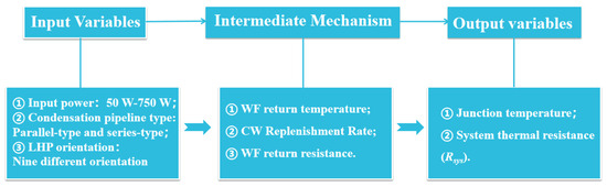
Figure 2.
Comprehensive performance orientation diagram.
2. LHP Design
2.1. Evaporator
In this study, a novel flat evaporator was developed, featuring a compact structure with a 90 mm long flat evaporator body and bilateral cover plates of 1 mm. The evaporator body was comprised of two primary components: CW and CC, with the CC positioned to the left side of the CW. The CW incorporated 22 uniformly distributed vapor pipelines arranged in a dual-row configuration to ensure a homogeneous vapor flow distribution. In order to further enhance the performance of the CC, a 1 mm thick layer of fine-grained copper powder (particle size < 38 μm) was sinter-deposited on its inner surface, achieving monolithic integration with the different porous sintered copper powder structure that significantly improved the structural integrity and heat transfer efficiency of the CC. Additionally, two 304 stainless steel annular components (8 mm width × 0.5 mm thickness) were embedded in the 1 mm thick sintered copper powder layer to enhance the mechanical strength of the CC. The thickness-directional configuration of the novel flat evaporator is presented in Figure 3.
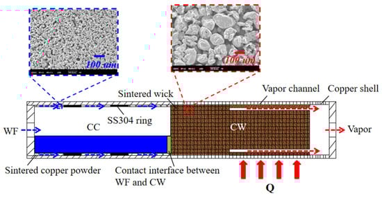
Figure 3.
Structure of the novel flat evaporator in the thickness direction.
2.2. Water-Cooled Condenser
This study presents a bilayered flow pipeline water-cooled plate condenser. The reasons why distilled water was chosen as the WF in this experiment are as follows. The commonly used agents in loop heat pipes are ammonia, distilled water, acetone, methanol, and ethanol. Among these common substances, distilled water is the most widely used, mainly because of distilled water (deionized water) has a high latent calorific value, is inexpensive and easy to obtain, generates no pollution and other advantages. As shown in Figure 4, the double-layer runner water-cooled condenser featured a symmetric structural design with a total thickness of 28 mm. Specifically, the thickness of both the upper and lower condensers was 11 mm, while the thickness of both the upper and lower condenser covers was 3 mm. The condenser assembly comprised M4 fastening bolts, symmetrically arranged upper/lower condensers and their corresponding protective cover plates. The upper and lower condensers were equipped with coolant inlets and outlets, respectively, and the outlet of the upper condenser was internally connected to the inlet of the lower condenser to form a continuous circulating flow path. The heat transfer path within the condenser was configured in both series and parallel pipeline arrangements. The pipeline layout of the condenser with a series condensation pipeline is shown in Figure 5. From Figure 5a, it is evident that the coolant flow path followed a serpentine configuration, while the condensation pipeline bayonet was positioned on the other side of the upper and lower condensers, as shown in Figure 5b.
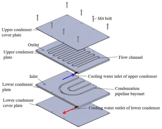
Figure 4.
Schematic diagram of the LHP condenser.
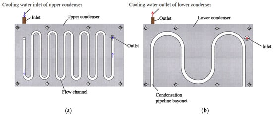
Figure 5.
The series condensation pipeline layout diagram. (a) The coolant flow path structure layout diagram. (b) The condensation pipeline layout diagram.
These bayonets were also arranged in a serpentine manner, and each bayonet featured a semicircular cross-section with a diameter of 6.1 mm, ensuring the stable installation of the condensation pipelines and facilitating efficient heat exchange. The piping layout of the condenser with a parallel condensation pipeline is shown in Figure 6. In comparison to Figure 5, the coolant flow path of the condenser with a parallel condensation pipeline also adopted a serpentine layout. However, the distinguishing feature was that its bayonet was configured in a parallel U-type arrangement.
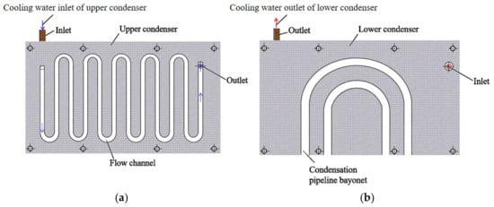
Figure 6.
The parallel condensation pipeline layout diagram. (a) The coolant flow path structure layout diagram. (b) The condensation pipeline layout diagram.
2.3. Overall Design of LHP
The general structural configuration of the flat evaporator LHP is shown in Figure 7, with its primary components including the flat evaporator, vapor pipeline, condensation pipeline, condenser, liquid pipeline, charge pipeline, and vacuum pipeline. Figure 7a shows the schematic structure of the LHP with a parallel condensation pipeline. As shown in the figure, the condensation section of this LHP comprised two copper tubes arranged in parallel, featuring a geometry that closely resembled a half-loop. These two parallel copper tubes were connected to the vapor pipeline and the liquid pipeline through two copper fittings. It was worth noting that the volume of the cavities inside the two copper fittings was included in the total volume of the vapor and liquid pipelines, respectively. Figure 7b shows the schematic structure of the LHP with a series condensation pipeline. As shown in Figure 7b, the pipeline of this LHP with a series condensation pipeline was configured in a single-pipe serpentine arrangement, and its structure can be regarded as comprising two or more pipes of the same diameter connected in series.
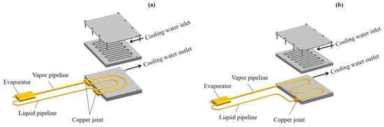
Figure 7.
Schematic diagram of a flat evaporator LHP: water-cooled LHP. (a) The schematic structure of the LHP with a parallel condensation pipeline. (b) The schematic structure of the LHP with a series condensation pipeline.
In this LHP design, the diameters of the vapor and condensation pipelines of the LHP were larger than that of the liquid pipeline, with the aim of facilitating a smoother countercurrent flow for the return of the WF to the evaporator during the circulation process. This design enhanced both the heat transfer efficiency and the overall performance of the system. To simplify the WF charging process, the system featured integrated pipelines for liquid filling and vacuum extraction, easing the filling procedure. The vacuum extraction pipeline was connected to the CC, while the condensation pipeline, liquid pipeline, and liquid filling pipeline were interconnected through a three-way device. Furthermore, the main geometric parameters of the flat evaporator LHP designed for this study are listed in Table 1. In this study, exploiting the advantages of distilled water—such as its high heat capacity, cost-effectiveness, and environmental friendliness—the aim was to utilize distilled water and determine its filling ratio α through a particular method:
where denotes the WF volume (mL) and signifies the total capacity of the internal space within the LHP (mL).

Table 1.
Main geometric parameters of LHPs for flat evaporators.
3. Results, Experimental Device and Process of LHP
3.1. Experimental Equipment and Apparatus
In the experiments assessing the heat transfer performance of the LHP, heat input was simulated using a heat source, as shown in Figure 8. We measured the junction temperature (Tj) using type-K thermocouples soldered to the effective heating surface of a rectangular copper block. To monitor the temperatures across different regions of the LHP, nine type-K thermocouples were strategically positioned along its surface, as shown in Figure 9, where the temperature sensors were labeled as the evaporator temperature (Te), CC temperature (Tcc), and evaporator outlet temperature (Tv). Additionally, three thermocouples were installed on the wall of the water-cooled condenser to measure the wall temperatures, designated as Tc1, Tc2, and Tc3. The ambient temperature (Ta) of the LHP was measured using a type-K thermocouple attached to a bracket near the LHP. As shown in Figure 10, the heat transfer performance testing system for the LHP consisted of the following components: the LHP, two DC power supplies (I and II), an industrial chiller, a constant temperature and humidity chamber, an Agilent 34970A data acquisition device (Santa Clara, CA, USA), and a computer. In the testing of the water-cooled LHP, the DC Power Supply II provided the heating power required for the simulated heat source, while the industrial chiller maintained a stable coolant temperature. The Agilent 34970A data acquisition instrument was used to collect temperature data from each measurement point of the LHP. A computer processed and analyzed this temperature information, while a constant temperature and humidity chamber ensured a consistent ambient temperature for the heat transfer performance test.
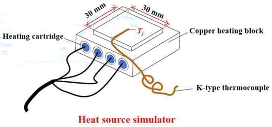
Figure 8.
Photo of the heat source simulator.
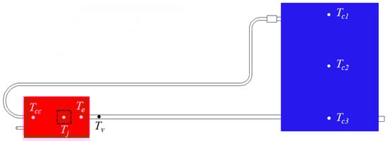
Figure 9.
Arrangement of the thermocouples. Thermocouples: junction temperature (Tj), evaporator temperature (Te), CC temperature (Tcc), evaporator outlet temperature (Tv), and condenser wall temperature (Tc1–Tc3).
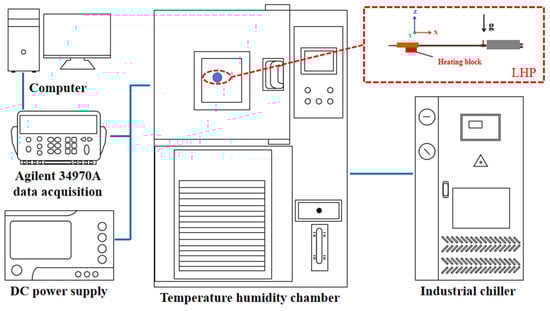
Figure 10.
Schematic of the heat transfer performance testing system.
3.2. Experimental Procedure
In this study, both the LHPs with series and parallel condensation pipelines were filled with liquid at a rate of 46.1%. The other main experimental parameters and control accuracy are shown in Table 2. This research primarily examined how the test orientation of the LHP, as well as the temperature and flow rate of the coolant, affected the heat transfer characteristics of the LHPs with series and parallel condensation pipelines. Figure 11 shows the testing orientations of an LHP with series or parallel condensation pipelines. In Figure 11, blue indicates the condenser, and brown marks the evaporator. When the condenser was positioned above the evaporator, the configuration was classified as a gravity-assisted orientation, specifically labeled as +90°, +60°, and +30° for orientations 1, 2, and 3, respectively. Conversely, when the condenser was placed below the evaporator, the configuration was classified as an anti-gravity orientation, with orientations 5, 6, and 7 designated as −10°, −20°, and −30°, respectively. Orientation 4 was defined as horizontal, where the plane that was formed by the vapor and liquid pipelines was parallel to the horizontal plane. In contrast, orientations 8 and 9 were side elevations, where the plane was formed by the vapor and liquid pipelines perpendicular to the horizontal plane. At orientation 8, the liquid pipeline was above the vapor pipeline, while at orientation 9, the vapor pipeline was above the liquid pipeline. During experiments to study the effect of the orientation on the heat transfer characteristics, the coolant temperature and flow rate were kept constant at 20 °C and 4 L/min, respectively.
Table 2.
Summary of experimental boundary conditions and parameter variation resolution.
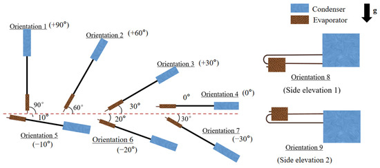
Figure 11.
Nine test orientations of the novel LHP with a flat evaporator.
3.3. Uncertainty Analysis of Experiments
In LHP heat transfer performance testing experiments, it is inevitable that there will be experimental errors. The experimental error mainly includes the temperature point of the test error and the instrument error of the relevant equipment. In this study, the uncertainties of the relevant experimental apparatus are listed in Table 3, where the uncertainty in the input power consists of the uncertainties in the input voltage and input current, which are defined as [25,26]:
where U is the input voltage, V; and I is the input current, A.
Table 3.
The uncertainty of the experimental instruments.
The uncertainty in the thermal resistance of the LHP consists of the uncertainty in the input power and the uncertainty in the temperature difference between the evaporator and condenser. It has been described as follows [25,26]:
where ΔTec is the temperature difference between the evaporator and condenser, °C.
Based on the above analysis, the maximum uncertainty of the input power is ±0.5%. For a water-cooled LHP with a series condensation pipeline in a horizontal test orientation, circulating cooling water temperature and flow rate of 20 °C and 4 L/min, respectively, and an input power of 750 W, the uncertainty in the thermal resistance of the LHP is ±1.36%. Similarly, the uncertainty in the total thermal resistance of the LHP system is ±0.80% under this test condition [27].
4. Experimental Results and Discussion
4.1. Effect of Orientations on Heat Transfer Characteristics of an LHP with a Parallel Condensation Pipeline
Figure 12 shows the variation in the heat source junction temperature (Tj) with the input power for the LHP with a parallel condensation pipeline under fixed cooling conditions (20 °C, 4 L/min) at multiple orientations. To provide a clearer analysis of the heat source junction temperature differences at various orientations of the LHP, Figure 13 shows a plot showing the temperature difference between any orientation i of the LHP and the horizontal orientation (orientation 4). As shown in Figure 12 and Figure 13, across the entire input power interval of 50 to 750 W, the heat source junction temperatures of the LHP at gravity-assisted orientations 1, 2, and 3 were consistently lower than those at the horizontal orientation (orientation 4). Specifically, the temperatures at gravity-assisted orientations remained lower than those observed at the horizontal orientation throughout the tested power interval. When the input power was below 350 W, the absolute value of the temperature difference between the heat source junction temperatures of gravity-assisted orientations 1, 2, and 3 and the horizontal orientation (Tj,1,2,3-Tj,4) decreased as the input power increases. However, when the input power exceeded 350 W, the absolute value of this temperature difference increased with further increases in the input power. This phenomenon was primarily attributed to the fact that, at low input power, the 1 mm copper powder within the walls of the CC can adequately ensure the supply of the WF in the CW, while the condenser exhibited a robust condensation capability. However, as the input power increased, the evaporation of the WF gradually escalated, leading to a reduction in the liquid level of the WF within the CC. This subsequently resulted in a decreased replenishment rate of the WF in the CW, causing the absolute temperature difference between the gravitational orientations 1, 2, and 3 and the horizontal orientations of the heat source junction temperature difference (Tj,1,2,3-Tj,4) to diminish. Conversely, when the input power continued to rise, the evaporation stabilized while the evaporation rate persisted. The two-phase zone lengthened the condensation pipeline, and the fluid level of the CC rose, increasing the replenishment rate of the CW and thereby raising the temperature difference (Tj,1,2,3-Tj,4). Across the input power interval of 50 to 750 W, the heat source junction temperatures at gravity-assisted orientations 1 and 2 were consistently lower than those at gravity-assisted orientation 3. Specifically, when the input power was below 700 W, the junction temperature at gravity-assisted orientation 1 was lower than at orientation 2. However, when the input power exceeded 700 W, the junction temperature at orientation 2 became lower than at orientation 1. This behavior was mainly attributed to the combined effects of the WF reflux resistance and the replenishment rate of the WF in the CW. The maximum temperature differences between the heat source junctions (Tj,1,2,3-Tj,4) for the LHP at gravity-assisted orientations 1, 2, and 3 compared to the horizontal orientation (orientation 4) were measured at 13.44 °C, 13.36 °C, and 9.37 °C, respectively. These values were achieved at input powers of 50 W, 50 W, and 750 W. In addition, the LHP at anti-gravity orientation 7 exhibited a significantly higher heat source junction temperature than the other orientations, achieving its maximum input power of 700 W with a corresponding temperature of 99.73 °C. At this time, the temperature difference (Tj,7-Tj,4) between orientation 7 and the horizontal orientation (orientation 4) peaked at 10.49 °C. At low input power (≤350 W) and high input power (≥650 W), the heat source junction temperature of the LHP at orientation 6 surpassed that of the horizontal orientation. Conversely, between 400 and 600 W, the heat source junction temperature at orientation 6 was lower than at the horizontal orientation. For the LHP at orientation 5, the heat source junction temperature was higher than that at the horizontal orientation (orientation 4) when the input power was below 300 W. However, once the input power exceeded 350 W, the heat source junction temperature at the horizontal orientation became lower than that at orientation 5. The causes of such phenomena were primarily associated with the reflux resistance of the WF, heat loss from the evaporator, and variations in the replenishment rate of the WF within the CW. For the LHP at orientation 8, the heat source junction temperature was lower than at the horizontal orientation (orientation 4) when the input power was below 300 W. However, once the input power exceeded 300 W, the heat source junction temperature at the horizontal orientation became even lower. This behavior can be attributed to the reflux resistance of the WF, the movement of the WF within the CC, and the distribution of vapor and liquid in the parallel condensation pipelines. At an input power of 50 W, the temperature difference (Tj,9-Tj,4) between orientation 9 and the horizontal orientation (orientation 4) reached a maximum absolute value of 6.79 °C. Additionally, when the input power was 750 W, the heat source junction temperatures for orientations 1, 2, 3, 4, 5, 6, 8, and 9 were measured at 82.81 °C, 82.34 °C, 83.97 °C, 93.34 °C, 91.36 °C, 96.83 °C, 98.68 °C, and 94.35 °C, respectively.
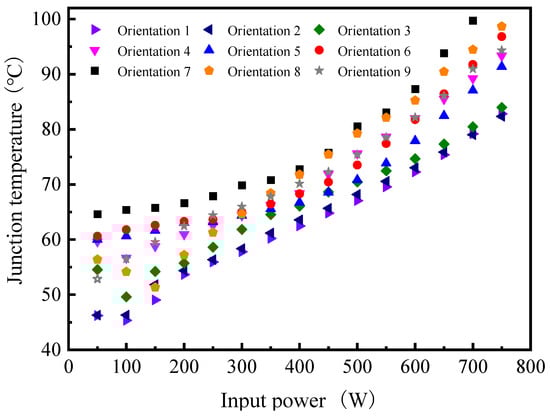
Figure 12.
Heat source junction temperature versus input power for the parallel condensation LHP at nine orientations.
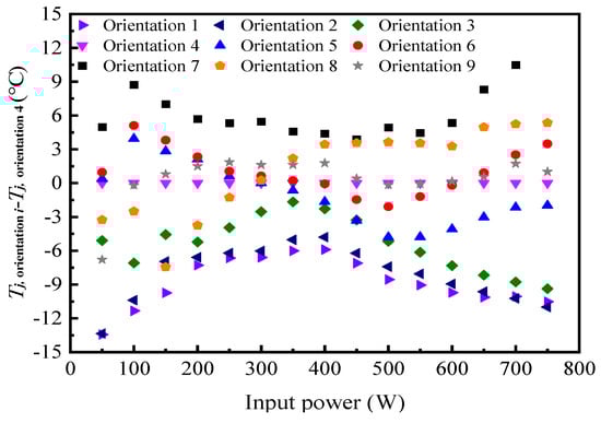
Figure 13.
Relationship between the temperature difference of the heat source junction of the LHP with a parallel condensation pipeline and the input power at different orientations.
During the heat transfer characteristics experiments, the thermal resistance was a critical parameter for evaluating the heat transfer performance of the LHP. Specifically, the thermal resistance of the LHP, denoted as RLHP, and the thermal resistance of the LHP system, referred to as Rsys, were defined as follows [28,29].
where is the condenser average temperature, °C. For water-cooled LHPs, Tcool refers to the temperature of the circulating coolant, and for air-cooled LHPs, Tcool denotes the temperature of the cooling air, °C. Q represents the input power, W.
Figure 14 shows the relationship between thermal resistance (including RLHP and Rsys) and input power for LHPs with a parallel condensation pipeline. The data were obtained under conditions of 20 °C coolant temperature and 4 L/min flow rate, at various orientations. As shown in Figure 14a,b, both the RLHP and Rsys displayed a similar trend in response to varying input power. Initially, both RLHP and Rsys decreased significantly with increasing input power before eventually stabilizing. The RLHP of the LHP at the seven orientations, specifically orientations 1, 2, 3, 4, 5, 6, and 9, arranged from smallest to largest, was as follows: orientation 1 < orientation 2 < orientation 3 < orientation 5 < orientation 4 < orientation 6 < orientation 9. Across the entire input power interval, the minimum values of the RLHP for test orientations 1 to 9 were as follows: 0.050 °C/W, 0.053 °C/W, 0.054 °C/W, 0.064 °C/W, 0.061 °C/W, 0.066 °C/W, 0.077 °C/W, 0.077 °C/W, and 0.068 °C/W, respectively. As shown in Figure 14b, when the input power exceeded 650 W, the Rsys of the nine orientations can be ranked from smallest to largest as follows: orientation 2 < orientation 1 < orientation 3 < orientation 5 < orientation 4 < orientation 9 < orientation 6 < orientation 8 < orientation 7. The minimum Rsys values across the entire input power interval for orientations 1 to 9 were 0.084 °C/W, 0.083 °C/W, 0.085 °C/W, 0.098 °C/W, 0.095 °C/W, 0.102 °C/W, 0.114 °C/W, 0.105 °C/W, and 0.099 °C/W, respectively. Table 4 shows the temperature difference of the heat source junction temperature between the LHP with series and parallel condensation pipelines under different LHP orientations.
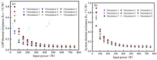
Figure 14.
Relationship between thermal resistance and input power of LHPs with a parallel condensation pipeline at different orientations: (a) RLHP; and (b) Rsys.
Table 4.
Junction temperature differences of the heat source between the LHP with series and parallel condensation pipelines at different LHP orientations.
At higher power inputs, parallel type condenser lines result in more liquid phase WF and higher levels within the compensation chamber due to the longer vapor phase region. In particular, at orientations 1, the WF needs to be transferred to the CW through the sintered copper powder wall, and the higher level significantly enhances the rate of work mass replenishment in the CW, which is more important than the effect of the WF reflux temperature, effectively preventing dryout. Similar mechanisms exist for orientations 2 and 3. The main reason for this is that the parallel construction may operate with only a single condenser tube, which promotes the return of the WF.
4.2. Comparison of the Effect of the Orientation on the Heat Transfer Performance of LHP with a Series/Parallel Condensation Pipeline
Our team previously explored the heat source junction temperature and thermal resistance characteristics of LHPs with series condensation pipelines at various orientations in another publication [29]. This study, however, focused on comparing the heat transfer performance differences between LHPs with parallel and series condensation pipelines. The flow characteristics and heat transfer mechanisms of gas–liquid two-phase flow within an LHP can vary significantly with the orientation, thereby influencing its heat transfer performance. For example, at vertical orientations, the liquid return was more influenced by gravity, whereas at horizontal orientations, the liquid return primarily depended on capillary forces. These orientation-induced changes affected the performance of both LHPs with series and parallel condensation pipelines. A comparative analysis of their heat transfer characteristics at identical orientations can provide deeper insights into how the condenser arrangement impacted the heat and mass transfer mechanisms of LHPs. To evaluate the steady-state operational characteristics of the flat evaporator water-cooled LHP, we experimentally investigated the relationship between the heat source junction temperature and the input power of LHPs with a series/parallel condensation pipeline at various orientations. The junction temperature data of the LHP with series condensation pipelines at various orientations in this comparative test were all cited from reference [29]. This investigation covered an input power interval from 50 to 750 W, with the coolant maintained at a temperature of 20 °C and a flow rate of 4 L/min. The comparative results of this relationship are shown in Figure 15. Figure 15a–c show the LHP with the condenser positioned above the evaporator at angles of 90° (orientation 1), 60° (orientation 2), and 30° (orientation 3). Figure 15d shows the horizontally oriented LHP (orientation 4). Figure 15e–g show the LHP with the condenser positioned below the evaporator at angles of −10° (orientation 5), −20° (orientation 6), and −30° (orientation 7). Figure 15h,i show the side elevation of the LHP, where the plane that was formed by the vapor and liquid pipelines is perpendicular to the horizontal plane. At orientation 8 (Figure 15h), the liquid pipeline was positioned above the vapor pipeline, while at orientation 9 (Figure 15i), the vapor pipeline was positioned above the liquid pipeline. At low power levels (e.g., 50 W), the LHP with a series condensation pipeline typically exhibited a lower heat source junction temperature (Tj).
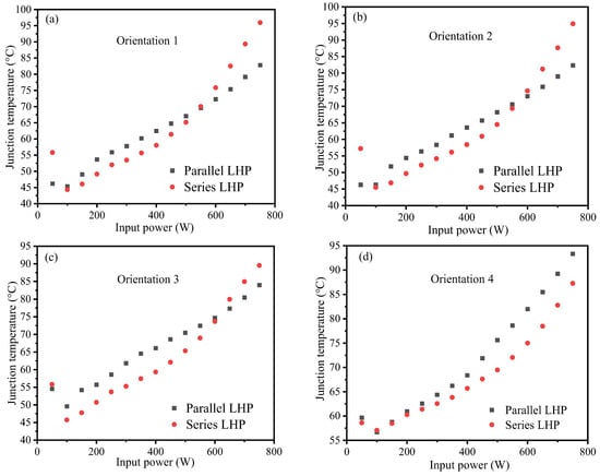
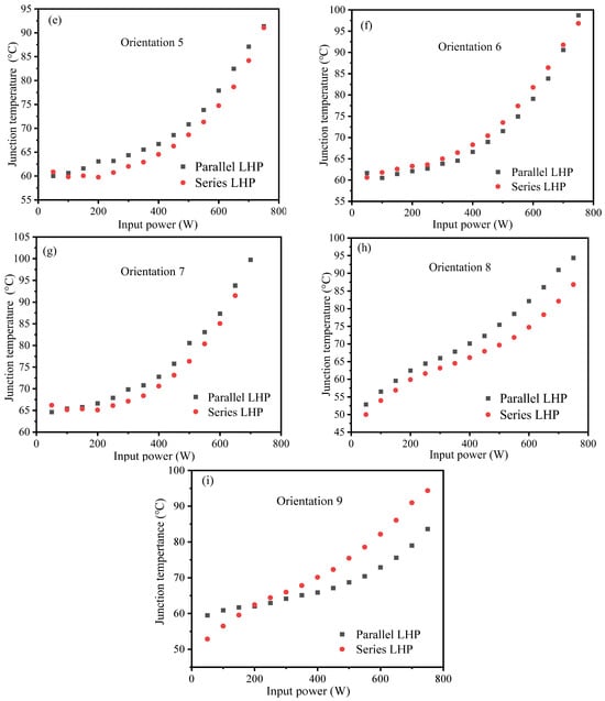
Figure 15.
Relationship between the heat junction temperature and the input power of the LHP at different orientations. (a) orientation 1; (b) orientation 2; (c) orientation 3; (d) orientation 4; (e) orientation 5; (f) orientation 6; (g) orientation 7; (h) orientation 8; (i) orientation 9.
From Figure 15, it can be seen that the performance trend of the LHP varied at most orientations as the input power increased. When the input power was raised to 300~600 W, the advantages of the LHP with a parallel condensation pipeline gradually became evident, demonstrating a lower heat source junction temperature Tj. At most orientations of the LHP, the temperature difference at the heat source junction between the LHP with a series condensation pipeline and the LHP with a parallel condensation pipeline was negative. However, when the LHP was positioned at orientation 1, with an input power interval of 550 to 750 W, the temperature difference at the heat source junction between the LHPs with a series condensation pipeline and with a parallel condensation pipeline became positive, increasing from 0.48 °C to 13.16 °C. This indicated that the LHP with a parallel condensation pipeline maintained a lower temperature at the heat source junction. Typically, condensers with a series condensation pipeline provide better condensation and lower return temperatures than condensers with a parallel condensation pipeline. However, at orientation 1, with input power between 550 and 750 W, the condenser with a series condensation pipeline exhibited higher heat source temperatures. This phenomenon, observed at orientations 2 and 3 as well, was attributed to the same causes as at orientation 1. When the LHP was at orientation 2 and the input power interval was from 600 to 750 W, the temperature difference at the heat source junction between the LHPs with a series and parallel condensation pipeline was positive, increasing from 1.60 °C to 12.56 °C. Similarly, at orientation 3, for input powers between 650 and 750 W, the temperature difference remained positive, rising from 2.62 °C to 5.56 °C. Additionally, at low input powers of 50 W or 100 W, the heat source junction temperature difference for certain orientations remained positive.
4.3. Theoretical Analysis of the Effect of the Orientation on the Heat Transfer Performance of LHP with a Series/Parallel Condensation Pipeline
At low input power, the evaporation rate of the WF in the LHP and the replenishment rate in the CW were minimal. Under these conditions, the reflux temperature of the WF in the CC played a critical role in determining the heat transfer performance of the system. As the input power increased, both the evaporation of the WF and the replenishment rate in the CW rose significantly. However, since the condensation conditions of the condenser remained constant, the return fluid temperature continued to increase with higher input power. Under high input power conditions, the replenishment rate of the WF in the CW became a more dominant factor influencing the heat transfer performance of the LHP [30]. When the LHP was oriented horizontally (Figure 15d), the heat source junction temperature of the LHP with a series condensation pipeline remained lower than that of the LHP with a parallel condensation pipeline across the entire input power interval (0–750 W). This can be attributed to the series-type condensation pipeline, which featured a single serpentine arrangement, resulting in a more uniform condensation field for the WF. Consequently, the condensation effect was enhanced, the subcooling degree of the liquid-phase WF in the condensation pipeline was elevated, and the temperature of the WF returning to the CC was reduced. In contrast, the parallel condensation pipeline consisted of two copper tubes arranged in parallel, which may have led to insufficient cooling of the WF in the condensation pipeline, thereby diminishing the condensation effect of the WF.
The WF mass flow rate ṁwf in the LHP was determined using the following expression:
where ṁwf represents the mass flow rate of the WF, measured in kg/s. Qapp denotes the input power, expressed in watts (W). hlv indicates the latent heat of vaporization of the liquid WF, measured in joules per kilogram (J/kg). The computational expression for the length of the two-phase region L2ϕ in the condenser was provided as below [31]:
where Tc denotes the temperature of the saturated liquid in the condenser, measured in °C. Tsink denotes the temperature of the circulating coolant, also measured in °C. x denotes the dryness fraction. (UA/L)f-s represents the overall heat transfer coefficient per unit length between the two-phase region of the condenser and the circulating coolant, expressed in W/K.
The expression for the calculation of (UA/L)f-s was given as below:
where hc,2ϕ represents the convective heat transfer coefficient between the WF and the inner pipe wall of the condensation pipeline in the two-phase region of the condenser, measured in W/(m2·K). dc,i and dc,o denote the inner and outer diameters of the condensation pipeline, respectively, measured in meters. λc−1 and λc−2 are the thermal conductivity coefficients of the condensation pipeline and the condenser, expressed in W/(m·K). tc indicates the thickness of the condensation pipeline bayonet along the circulating coolant flow path in the single-layer condenser, measured in meters. Ac refers to the condensation area of the condenser, in square meters. Lc signifies the length of the condensation pipeline, measured in meters. hc,o is the convective heat transfer coefficient between the WF and the circulating coolant as well as the condenser thickness, measured in meters.
The computational expression for hc,2ϕ was presented as below [32]:
where hc,1ϕ denotes the condenser in the single-phase region of the WF and the condensation pipeline, which corresponds to the wall of the convection heat transfer coefficient, measured in W/(m2·K). ρl and ρv represent the liquid mass density and gas mass density, respectively, measured in kg/m3.
The computational expression for hc,1ϕ was presented as below [33]:
where Rel,c represents the Reynolds number of the liquid-phase medium within the condenser. Prl,c denotes the Prandtl number of the liquid-phase medium in the condenser.
The equation for determining the length of the single-phase zone L1ϕ within the condenser was provided as below:
Equations (7)–(12) are applicable to a copper/water LHP with 20 °C cooling water, 4 L min−1 flow rate, and 50–750 W heat load, ignoring the axial heat conduction and tube wall heat capacity. When the system is in an unsteady state and has a very low heat load, the above three equations may produce deviations [32].
The calculated results are presented in Figure 16. Under low input power conditions, as the input power increased, the length of the single-phase region in the condenser of the LHP decreased, while the length of the two-phase region increased. Notably, both the series and parallel condensation pipeline configurations of the LHP exhibited similar trends, indicating a reduction in the condensability of the WF within the system. When the input power exceeded 550 W, the lengths of both the single-phase and two-phase regions gradually stabilized. Figure 16 also shows that, across the entire experimental input power interval, the LHP with a parallel condensation pipeline exhibited a longer two-phase region compared to the series configuration. This observation suggested that the LHP with a series condensation pipeline demonstrated higher condensation efficiency. Additionally, the lower WF reflux temperature in the series configuration contributed to its superior performance. Overall, the heat transfer performance of the LHP with a series/parallel condensation pipeline was predominantly influenced by the WF reflux temperature and the amount of WF present in the CC.
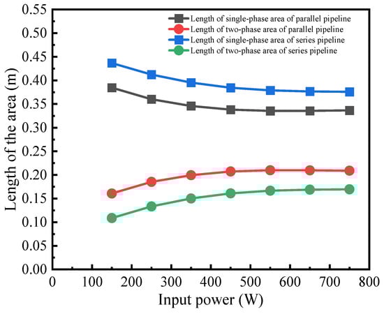
Figure 16.
Relationship between the single/two phase region length and the input power in a condenser with a series/parallel condensation pipeline.
As shown in Figure 15d, under low input power conditions (0–200 W), the temperature difference between the heat source junctions of LHPs equipped with series and parallel condensation pipelines was minimal. However, as the input power increased beyond this interval, a notable divergence emerged: the heat source junction temperature of LHPs with a parallel condensation pipeline rose significantly higher than that of LHPs with a series condensation pipeline. This resulted in a progressively widening temperature difference between the two configurations. The observed phenomenon can be attributed to the fact that under low input power conditions, the evaporation of the WF was minimal, resulting in negligible differences in the condensation performance between the series and parallel condensation pipeline configurations within the condenser. As the input power increased, both the vapor flow rate and temperature rose, leading to a significant increase in the temperature of the WF returning to the CC in LHPs with a parallel condensation pipeline. This behavior is further shown in Figure 17, which shows the distribution of the WF in the CC. While there was a variation in the liquid volume between the series and parallel condensation pipelines, this variation had minimal impact on the fluid level within the CC. Ultimately, the temperature differential at the junctions of LHPs with series and parallel condensation pipelines gradually increased under these conditions.
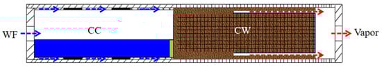
Figure 17.
Distribution of the vapor–liquid phase in the evaporator at the horizontal orientation.
At the gravity-assisted orientation, the WF could not directly contact the CW. Instead, the fluid within the CW was transmitted through a 1 mm thick layer of sintered copper powder lining the wall of the CC, ensuring proper heat pipe operation. This study examined three distinct cases at the gravity-assisted orientation, referred to as orientations 1, 2, and 3, with a particular emphasis on orientation 1. The specific mass distribution within the system is shown in Figure 18a. At low input power, the evaporation of the WF was reduced, allowing the condensed WF to flow back into the CC more smoothly under gravitational influence. This ensured that the 1 mm thick sintered copper powder lining the inner wall of the CC effectively maintained the supply of WF within the CW. Additionally, due to efficient condensation of the vapor-phase WF, the temperature of the returning liquid was lower. As a result, the wick temperature of the LHP with a series or parallel condensation pipeline was generally lower under low input power conditions. However, as the input power increased, the evaporation rate of the WF rose, while the condensation conditions of the condenser remained unchanged. This imbalance led to a gradual increase in the temperature of the returning WF. As shown in Figure 15a, under low input power conditions (50–550 W), the LHP with a series condensation pipeline exhibited a lower heat source junction temperature compared to that with a parallel condensation pipeline. This phenomenon can be attributed to the significant influence of the WF reflux temperature on the system heat transfer performance at low input power levels. Under these conditions, the evaporation rate of the WF was relatively low, and the condenser in the series-type tubing arrangement operated more efficiently than that in the parallel-type arrangement. This higher efficiency resulted in the lower temperature of the WF returning to the CC. Therefore, the series condensation pipeline configuration led to more effective cooling of the heat source junction, as evidenced by the lower temperatures observed. At high input power levels (550–750 W), the influence of the WF reflux temperature on the system heat transfer performance diminished, and the replenishment rate of the WF in the CW became the dominant factor. The parallel condensation pipeline exhibited suboptimal condensation performance, leading to a longer vapor-phase region and a higher volume of liquid-phase WF in the CC. However, as the volume of liquid-phase WF in the CC increased, the liquid level rose, accelerating the replenishment rate of the WF in the CW. Consequently, under these operating conditions, the heat source junction temperature of the LHP with a parallel condensation pipeline was lower.
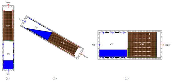
Figure 18.
Distribution of the vapor–liquid phase in the evaporator at three typical orientations. (a) LHP at +90° orientation. (b) LHP at −30° orientation. (c) LHP at side elevation orientation.
At the anti-gravity orientation, the CC ensured adequate WF replenishment in the CW. The dominant factors influencing the system heat transfer were the WF reflux resistance and reflux temperature. The specific distribution of the WF is shown in Figure 18b. This study examined three distinct cases at anti-gravity orientations—orientations 5, 6, and 7, with particular emphasis on the scenario where the LHP was positioned at orientation 7. As shown in Figure 15g, across most of the input power interval (50–700 W), the LHP with a series condensation pipeline demonstrated a lower heat source junction temperature. This was attributed to the efficient condensation performance of the WF in the condenser with a series condensation pipeline, which resulted in a lower temperature for the WF returning to the CC. However, when the input power exceeded 700 W to 750 W, the heat source junction temperature of the LHP with a parallel condensation pipeline became lower. This shift can be explained by several factors: the condenser with a parallel condensation pipeline had relatively lower cooling efficiency and primarily contained a vapor-phase medium. In contrast, the series condensation pipeline was predominantly filled with a liquid-phase medium. Consequently, the reflux resistance in the parallel condensation pipeline was reduced, enhancing the overall heat transfer characteristics of the system and leading to a lower medium reflux temperature. This improvement in heat transfer performance resulted in the lower return temperature of the WF.
When the LHP was positioned at the side elevation orientation, the distribution of the WF was as shown in Figure 18c. The temperature trend at the heat source junction was primarily governed by the interplay between gravitational forces and the rate of WF replenishment within the CW. This study examined two distinct scenarios at the side elevation orientation, specifically orientations 8 and 9. At orientation 8, where the liquid pipeline of the system was positioned above the vapor pipeline, the gravitational force acting on the WF in the condenser pipeline negatively impacted the thermal performance of the LHP. Conversely, the gravitational force in the liquid pipeline positively contributed to the thermal performance of the LHP. From Figure 15h, it can be observed that the LHP with a series condensation pipeline consistently exhibited a lower heat source junction temperature across the entire input power interval investigated in this study. This behavior can primarily be attributed to the fact that at low input power levels, evaporation of the WF was minimal, and the CC contained sufficient WF to replenish the CW. As a result, the temperature of the returning WF became the dominant factor influencing the heat transfer characteristics of the system. Furthermore, the LHP with a series condensation pipeline demonstrated a more pronounced condensation effect compared to the LHP with a parallel condensation pipeline, leading to the lower temperature of the returning fluid. As the input power increased, in the LHP with a parallel condensation pipeline configuration, the condensation performance deteriorated, resulting in an increased volume of liquid-phase WF being returned to the CC. However, this change had minimal impact on the liquid level of the WF within the chamber. Consequently, the temperature of the returning WF remained the dominant factor influencing the system heat transfer characteristics. At orientation 9, where the vapor pipeline was positioned above the liquid pipeline within the system, the gravitational effect on the WF in the condensation pipeline differed from that observed at orientation 8. As shown in Figure 15i, the LHP with a series condensation pipeline maintained a relatively low heat source junction temperature at low input power levels. However, as the input power increased, the LHP with a parallel condensation pipeline demonstrated a lower heat source junction temperature. When the input power was below 200 W, the evaporation of the WF was diminished, leading to a reduced volume of condensed WF within the condenser and decreased resistance for the WF to return to the CC. In this scenario, the LHP with a series condensation pipeline demonstrated efficient condensation, resulting in the lower temperature of the fluid returning to the CC. When the input power exceeded 200 W, the evaporation of the WF intensified. The condenser with a parallel condensation pipeline exhibited slightly less effective condensation. However, the WF in the pipeline predominantly remained in the vapor phase. In contrast, the condenser with a series condensation pipeline, due to its superior condensation effect, retained a higher proportion of WF in the liquid phase within the pipeline. The gravitational force acting on the liquid-phase WF in this configuration negatively impacted the thermal performance of the LHP. Consequently, the LHP with a parallel condensation pipeline experienced reduced WF reflux resistance. The level of WF in the CC facilitated the replenishment of the CW. In this scenario, the influence of the reflux resistance and the WF replenishment rate in the CW on the system heat transfer performance outweighed that of the WF reflux temperature. As a result, the LHP with a parallel condensation pipeline demonstrated greater advantages, leading to a lower heat source junction temperature.
Combined with the above experimental results, the LHP system in this study is compared with the four references mentioned in the introduction as shown in Table 5.
Table 5.
Comparison of LHP systems in the literature.
The novel LHP system proposed in this study demonstrates low thermal resistance, high input power density, and full orientation adaptability at the chip level through structural innovation and systematic orientation optimization. It significantly outperforms similar systems documented in the existing literature and offers an efficient and compact solution for high-power chip heat dissipation.
5. Conclusions
In the realm of data center chip cooling, this study introduces the design and study of a novel water-cooled flat-plate LHP. The aim of this new LHP evaporator design is to boost the thermal performance of conventional flat-plate LHPs. This makes it a promising solution for cooling chips with high heat flux density. The heat transfer characteristics of this new LHP were examined at nine different orientations under cooling conditions of 20 °C water temperature and 4 L/min flow rate. The key findings were as follows.
(1) The novel flat evaporator LHP demonstrated remarkable heat transfer performance at the horizontal orientation, achieving up to 750 W with a heat source junction temperature of 93.34 °C. Across the entire input power interval from 50 to 750 W, the heat source junction temperature at the gravity-assisted orientation remained consistently lower than at the horizontal orientation. Specifically, at the maximum input power of 750 W, the temperature at orientation 2 was 11 °C lower than at the horizontal orientation. Conversely, at the anti-gravity orientation (orientation 7), the heat transfer performance peaked at 700 W, with the heat source temperature increasing by 10.49 °C compared to the horizontal orientation. When positioned at the side elevation orientation, at 750 W, the heat source temperatures at orientations 8 and 9 surpassed those of the horizontal orientation, with orientation 8 reaching 98.68 °C, a 5.34 °C elevation from the horizontal orientation. These findings underscored the significant influence of orientation changes on the heat source junction temperature, particularly under high input power conditions.
(2) Under low power conditions, the LHP with a series condensation pipeline typically showed lower heat source junction temperatures than the parallel configuration due to its enhanced condensation effect. When operating at high power and positioned horizontally, the LHP with a series condensation pipeline continued to outperform the parallel design. However, at a gravity-assisted orientation, the LHP with a series condensation pipeline heat source junction temperature surpassed that of the LHP with a parallel condensation pipeline once the input power exceeded 600 W. Notably, when the LHP was at an anti-gravity orientation, between 700 and 750 W, the LHP with a parallel condensation pipeline achieved even lower heat source junction temperatures. At the side elevation orientation, the LHP with a series condensation pipeline maintained lower temperatures for orientation 8. For orientation 9, when the input power exceeded 200 W, the LHP with a series condensation pipeline heat source junction temperature began to exceed that of the LHP with a parallel condensation pipeline, with the temperature difference widening as the input power increased.
(3) The impact of the orientation (gravity-assisted, anti-gravity, and side elevation) on the system heat transfer characteristics was primarily reflected in the interplay of the WF reflux temperature, reflux resistance, and CW liquid replenishment rate. The condenser with a series condensation pipeline exhibited a lower fluid reflux temperature under low input power and gravity-assisted conditions, while the condenser with a parallel condensation pipeline showed a reduced heat source junction temperature under high input power and specific orientations (e.g., orientation 9), attributed to its lower reflux resistance and favorable liquid level. This highlighted that the heat transfer performance of LHPs with series/parallel condensation pipelines was predominantly influenced by the operational fluid reflux temperature, condensation efficiency, and CW fluid replenishment rate. Therefore, the optimal configuration should be determined based on the specific operating conditions.
(4) Data center applicability: Under 20 °C/4 L min−1 water cooling conditions, the system can stably output 750 W, meeting the cooling needs of next-generation CPUs/GPUs (>500 W). The parallel piping design reduces the space usage by 30%, making it suitable for high-density racks (>30 kW rack−1), providing a scalable, modular solution for chip-level liquid cooling in data centers.
Author Contributions
Conceptualization, K.X.; methodology, K.X.; formal analysis, Y.L.; investigation, K.X.; data curation, K.X.; writing—original draft preparation, K.X., Y.L. and Z.L.; writing—review and editing, Q.P.; supervision, K.X.; project administration, K.X.; funding acquisition, K.X. All authors have read and agreed to the published version of the manuscript.
Funding
This research was funded by (1) Science Start-up Foundation of Xi’an University of Architecture and Technology [grant number 1960324008]; (2) National Fund Cultivation Project of Xi’an University of Architecture and Technology [grant number 019/1960524133]; (3) China Postdoctoral Science Foundation [grant number 2024MD753964]; (4) Independent Research and Development project of State Key Laboratory of Green Building [grant number LSZZ-Y202417]; (5) Postdoctoral Research Project Grant of Shaanxi [grant number 019/1608725012]; (6) Natural Science Basic Research Program of Shaanxi [grant number 2025JC-YBQN-738]; (7) “School Recruitment Sharing” Talent Attraction and Employment Special Program of Shaanxi [grant number 019/1960325046]; and (8) Sanqin Talent Introduction Program for Outstanding Young Engineering Talents [grant number 019/1960325067].
Data Availability Statement
The supporting data will be made available on request.
Conflicts of Interest
The authors declare no conflicts of interest.
Abbreviations
The following abbreviations are used in this manuscript:
| Nomenclature | |
| A | area, m2 |
| CC | compensating chamber |
| CRAH | computer room air conditioning |
| CW | capillary wick |
| DC | direct current |
| h | heat transfer coefficient, W/(m2·°C) |
| hfg | latent heat of evaporation, J/kg |
| I | input current, A |
| ID | inner diameter, m |
| K | permeability, m2 |
| L | length, m |
| LHP | loop heat pipe |
| OD | outer diameter, m |
| ΔP | pressure drop, Pa |
| Δh | height difference, m |
| Q | heat load, W |
| R | thermal resistance, °C/W |
| Re | Reynolds number |
| rc | effective pore radius, m |
| T | temperature, °C |
| t | thickness, m |
| U | input voltage, V |
| (UA/L)f-s | the overall heat transfer coefficient per unit length between the two-phase region of the condenser and the circulating coolant, W/K. |
| volume, mL | |
| W | width, m |
| WF | working fluid |
| x | dryness fraction |
| Greek symbols | |
| u | velocity, m/s |
| μ | viscosity, kg/m·s |
| θ | contact angle, ° |
| ρ | density, kg/m3 |
| σ | surface tension, N/m |
| Subscripts and superscripts | |
| a | ambient |
| app | applied |
| c | condenser |
| cap | capillary |
| cc | compensation chamber |
| cool | cooling |
| e | evaporator |
| ec | evaporator and condenser |
| g | gravity |
| i | inner |
| in | inlet |
| j | junction |
| l | liquid |
| ll | liquid line |
| lv | latent heat of vaporization |
| out | outlet |
| sink | sink |
| sys | system |
| tot | total |
| v | vapor |
| vc | vapor channel |
| vl | vapor line |
| w | wick |
| wf | working fluid |
| 1ϕ | the single-phase zone |
| 2ϕ | the two-phase zone |
References
- Li, D.; Song, J.; Liu, H.; Jiang, J. Simulators for Conversing Power to Thermal on Green Data Centers: A Review. Energies 2024, 17, 5631. [Google Scholar] [CrossRef]
- Cheng, H.; Yang, T.; Cheng, Q.; Zhao, Y.; Wang, L.; Yuan, W. Influence of Non-Uniform Airflow on Two-Phase Parallel-Flow Heat Exchanger in Data Cabinet Cooling System. Energies 2025, 18, 923. [Google Scholar] [CrossRef]
- Kargar, S.; Moran, J.L. Combining direct and indirect free cooling for data centers via transformation into a building-scale heat exchanger. Appl. Energy 2025, 392, 125973. [Google Scholar] [CrossRef]
- Nada, S.A.; Said, M.A. Comprehensive study on the effects of plenum depths on air flow and thermal managements in data centers. Int. J. Therm. Sci. 2017, 122, 302–312. [Google Scholar] [CrossRef]
- Li, N.; Li, H.; Duan, K.; Tao, W.-Q. Evaluation of the cooling effectiveness of air-cooled data centers by energy diagram. Appl. Energy 2025, 382, 125215. [Google Scholar] [CrossRef]
- Bai, Y.; Gu, L.; Qi, X. Comparative Study of Energy Performance between Chip and Inlet Temperature-Aware Workload Allocation in Air-Cooled Data Center. Energies 2018, 11, 669. [Google Scholar] [CrossRef]
- Liao, J.; Yang, C.; Yang, H. Experimental study and information entropy analysis on periodic performance of a PCM thermal management system for blade servers in data centers. Int. J. Therm. Sci. 2023, 188, 108216. [Google Scholar] [CrossRef]
- Zhang, H.; Ye, F.; Guo, H.; Yan, X. Isothermal Performance of Heat Pipes: A Review. Energies 2022, 15, 1992. [Google Scholar] [CrossRef]
- Zhao, Y.; Wei, M.; Dan, D. Modeling, Design, and Optimization of Loop Heat Pipes. Energies 2024, 17, 3971. [Google Scholar] [CrossRef]
- Wang, Y.; Huang, X.; Chu, J.; Du, Y.; Tang, X.; Dai, C.; Ma, G. Analysis of an Evaporative Condensation System Coupled to a Microchannel-Separated Heat Pipe for Data Centers. Energies 2022, 15, 9056. [Google Scholar] [CrossRef]
- Tang, Y.; Zhang, X.; Liu, Z. Experimental Study on the Thermal Performance of Flat Loop Heat Pipe Applied in Data Center Cooling. Energies 2023, 16, 4677. [Google Scholar] [CrossRef]
- Goshayeshi, H.R.; Mousavi, S.B.; Heris, S.Z.; Chaer, I. Insights into two-phase flow dynamics in closed-loop pulsating heat pipes utilizing Fe3O4/water: Experimental visualization study. Sci Rep. 2024, 14, 16497. [Google Scholar] [CrossRef]
- Xue, Z.H.; Ai, B.C.; Qu, W. Data center energy conservation study utilizing loop heat pipes as a chip-level cooling technique and its industrial application. Appl. Therm. Eng. 2023, 220, 119715. [Google Scholar] [CrossRef]
- Wang, H.; Lin, G.; Guo, Y.; Zhao, W.; Bai, L. Experimental study of a high-capacity dual compensation chamber loop heat pipe at different orientations. Int. J. Therm. Sci. 2024, 202, 109051. [Google Scholar] [CrossRef]
- Guessi Domiciano, K.; Krambeck, L.; Barbosa Henriques Mantelli, M. Novel mini loop heat pipe with twisted wires as wick structure. Appl. Therm. Eng. 2025, 260, 124992. [Google Scholar] [CrossRef]
- Cui, J.; Ling, W.; Zhou, W.; Hu, Z.; Zhu, Y. Influence of microchannel condenser with different change rate of cross-sections along the flow field on the anti-gravity performance of loop heat pipe. Int. J. Heat Mass Transf. 2024, 224, 125305. [Google Scholar] [CrossRef]
- He, S.; Zhou, P.; Liu, W.; Liu, Z. Experimental study on thermal performance of loop heat pipe with a composite-material evaporator for cooling of electronics. Appl. Therm. Eng. 2020, 168, 114897. [Google Scholar] [CrossRef]
- Tharayil, T.; Asirvatham, L.G.; Ravindran, V.; Wongwises, S. Thermal performance of miniature loop heat pipe with graphene–water nanofluid. Int. J. Heat Mass Transf. 2016, 93, 957–968. [Google Scholar] [CrossRef]
- Zhu, K.; Li, X.; Li, H.; Yang, Z.; Wang, Y. Experimental investigation on the effect of heat sink temperature on operational characteristics of a new-type loop heat pipe. Energy Procedia 2019, 158, 2423–2429. [Google Scholar] [CrossRef]
- Li, J.; Lv, L. Performance investigation of a compact loop heat pipe with parallel condensers. Exp. Therm. Fluid Sci. 2015, 62, 40–51. [Google Scholar] [CrossRef]
- Tang, Y.; Zhou, R.; Lu, L.; Xie, Z. Anti-Gravity Loop-shaped heat pipe with graded pore-size wick. Appl. Therm. Eng. 2012, 36, 78–86. [Google Scholar] [CrossRef]
- Xu, J.; Ji, X.; Yang, W.; Zhao, Z. Modulated porous wick evaporator for loop heat pipes: Experiment. Int. J. Heat Mass Transf. 2014, 72, 163–176. [Google Scholar] [CrossRef]
- Zhou, G.; Li, J.; Jia, Z. Power-saving exploration for high-end ultra-slim laptop computers with miniature loop heat pipe cooling module. Appl. Energy 2019, 239, 859–875. [Google Scholar] [CrossRef]
- Zhou, G.; Li, J. Two-phase flow characteristics of a high loop heat pipe with flat evaporator under gravity. Int. J. Heat Mass Transf. 2018, 117, 1063–1074. [Google Scholar] [CrossRef]
- Zhang, Z.; Zhang, H.; Ma, Z.; Liu, Z.; Liu, W. Experimental study of heat transfer capacity for loop heat pipe with flat disk evaporator. Appl. Therm. Eng. 2020, 173, 115183. [Google Scholar] [CrossRef]
- Tharayil, T.; Asirvatham, L.G.; Ravindran, V.; Wongwises, S. Effect of filling ratio on the performance of a novel miniature loop heat pipe having different diameter transport lines. Appl. Therm. Eng. 2016, 106, 588–600. [Google Scholar] [CrossRef]
- Xiong, K.; Meng, L.; Wang, S.; Zhang, L.W. Experimental investigation on thermal characteristics of a novel loop heat pipe for cooling high heat flux electronic chips. Int. J. Heat Mass Transf. 2022, 187, 122569. [Google Scholar] [CrossRef]
- Maydanik, Y.; Chernysheva, M.; Vershinin, S. High-Capacity Loop Heat Pipe with Flat Evaporator for Efficient Cooling Systems. J. Thermophys. Heat Transf. 2020, 34, 465–475. [Google Scholar] [CrossRef]
- Maydanik, Y.F.; Vershinin, S.V.; Chernysheva, M.A. Experimental study of an ammonia loop heat pipe with a flat disk-shaped evaporator using a bimetal wall. Appl. Therm. Eng. 2017, 126, 643–652. [Google Scholar] [CrossRef]
- Jung, E.G.; Boo, J.H. Experimental observation of thermal behavior of a loop heat pipe with a bypass line under high heat flux. Energy 2020, 197, 117241. [Google Scholar] [CrossRef]
- Xiong, K.; Chen, Y.; Zhang, W.; Wang, S. Establishment and analysis of a new steady-state operation model of loop heat pipe. Int. Commun. Heat Mass Transf. 2025, 163, 108754. [Google Scholar] [CrossRef]
- Chernysheva, M.A.; Yushakova, S.I.; Maydanik, Y.F. Effect of external factors on the operating characteristics of a copper–water loop heat pipe. Int. J. Heat Mass Transf. 2015, 81, 297–304. [Google Scholar] [CrossRef]
- Xu, J.; Wang, Z.; Xu, H.; Zhang, L. Experimental research on the heat performance of a flat copper-water loop heat pipe with different inventories. Exp. Therm. Fluid Sci. 2017, 84, 110–119. [Google Scholar] [CrossRef]
Disclaimer/Publisher’s Note: The statements, opinions and data contained in all publications are solely those of the individual author(s) and contributor(s) and not of MDPI and/or the editor(s). MDPI and/or the editor(s) disclaim responsibility for any injury to people or property resulting from any ideas, methods, instructions or products referred to in the content. |
© 2025 by the authors. Licensee MDPI, Basel, Switzerland. This article is an open access article distributed under the terms and conditions of the Creative Commons Attribution (CC BY) license (https://creativecommons.org/licenses/by/4.0/).