Article

Total Internal Reflection End-Pumped Solar Laser with the Solar-to-Laser Conversion Efficiency of 6.09%

by
Lin Wang
,
Haiyang Zhang
*,
Dário Garcia
,
Weichen Xu
,
Changming Zhao
and
Anran Guo
School of Optics and Photonics, Beijing Institute of Technology, Beijing 100081, China
*
Author to whom correspondence should be addressed.
Energies 2025, 18(15), 4033; https://doi.org/10.3390/en18154033
Submission received: 1 July 2025 / Revised: 23 July 2025 / Accepted: 28 July 2025 / Published: 29 July 2025
(This article belongs to the Section A2: Solar Energy and Photovoltaic Systems)

Abstract

A novel total internal reflection solar end-pumped laser system has been introduced for the first time, aimed at enhancing the solar-to-laser conversion efficiency. Utilizing a conical solid or cavity reflector, this system refocuses sunlight from a 0.2818 m 2 parabolic mirror into a single Ce (0.05 at.%): Nd (1 at.%): YAG crystal rod, measuring 4 mm in diameter and 10 mm in length, thereby promoting total internal reflection and extending the pumping path. Simulation results indicate that under the same solar input power conditions (249.05 W), the conversion efficiencies of the conical solid reflector and cavity reflector systems are 1.2 times and 1.33 times higher than the current highest recorded efficiency of single-rod systems, respectively. At 950 W/m 2 , the conical reflector reaches 5.48% efficiency, while the cavity reflector attains 6.09%. Their collection efficiencies are 52.03 W/m 2 and 57.90 W/m 2 , with slope efficiencies of 6.65% and 7.72%.

1. Introduction

Solar energy stands as a prevalent and clean power source on Earth. Its applications are diverse and extensive, encompassing solar power plants, solar streetlights, and solar water heaters. In the realm of space, solar energy emerges as a vital energy source for spacecraft. A notable application of solar energy is the solar-pumped laser (SPL), which directly converts sunlight into laser light, thereby eliminating the intermediate electrical conversion stage. This direct conversion endows SPL with significant potential for applications in space, particularly in fields such as space-based laser communication [1] and solar power generation systems [2,3] in orbit.
Research on SPL can be traced back to 1963, when Kiss and colleagues utilized a CaF 2 : Dy 2 + medium under liquid neon cooling to achieve a continuous laser output at 2.36 μ m [4]. In 1966, the first SPL employing neodymium-doped yttrium aluminum garnet (Nd:YAG) as the laser medium emerged, achieving a power output of 1 W [5]. Subsequently, numerous materials were experimented with for use in SPL, but it was ultimately determined that solid laser media with a YAG substrate displayed superior compatibility with sunlight.
In 2003, Lando and colleagues implemented a two-dimensional compound parabolic concentrator for the side pumping of Nd:YAG crystal laser rods. They defined the collection efficiency by the ratio of output power to the area of concentration, thereby evaluating the performance of solar laser systems, ultimately achieving a collection efficiency of 6.7 W/m 2 [6]. Following this, enhancing the collection efficiency became a pivotal objective of SPL research. In 2007, Yabe and his team employed a 1.3 m 2 Fresnel lens to pump a Cr:Nd:YAG ceramic, achieving a laser output of 24.4 W, and the collection efficiency was measured at 18.7 W/m 2 , corresponding to a solar-to-laser conversion efficiency (SLCE) of 2.40% [7]. By 2011, Liang et al. achieved a collection efficiency of 19.3 W/m 2 using a 0.64 m 2 Fresnel lens to pump a Nd:YAG crystal, with an SLCE of approximately 2.17% [8]. The following year, Dinh and colleagues reported achieving a power output of 120 W by pumping a Nd:YAG crystal with a 4 m 2 Fresnel lens, resulting in a collection efficiency of 30 W/m 2 and an SLCE of about 3.26% [9]. In 2017, Liang et al. employed a 1.54 m 2 parabolic mirror to end-pump a Nd:YAG crystal, achieving a collection efficiency of 31.5 W/m 2 and an SLCE of approximately 3.15% [10]. The subsequent year, they also pumped a Cr:Nd:YAG ceramic with a 1 m 2 parabolic mirror, achieving a collection efficiency of 32.5 W/m 2 and an SLCE of approximately 3.74% [11].
In 2018, Guan et al. continued their exploration with an Nd:YAG crystal, bonding a segment of YAG at the end. By employing a 1.03 m 2 Fresnel lens, they achieved a collection efficiency of 32.1 W/m 2 , with a corresponding SLCE of 3.3% [12]. In 2020, Vistas et al. pioneered the first SPL based on Ce:Nd:YAG, although it only attained a collection efficiency of 4.9 W/m 2 [13]. At that time, research indicated that Ce:Nd:YAG could serve as an effective alternative to Cr:Nd:YAG [14,15,16]. The following year, Vistas et al. developed a new end pumping scheme with Ce:Nd:YAG, achieving a collection efficiency of 23.6 W/m 2 and an SLCE of 2.8%, which represented enhancements of 1.57 and 1.56 times, respectively, compared to Nd:YAG [17].
In 2022, Garcia et al. employed a parabolic mirror to end-pump a Ce:Nd:YAG crystal, achieving a collection efficiency of 38.22 W/m 2 , along with an SLCE for a single rod at 4.5% [18]. That same year, Liang et al. utilized a laser head structure composed of three Ce:Nd:YAG rods, which resulted in a collection efficiency of 41.25 W/m 2 and an SLCE of 4.64%—the highest achieved to date [19]. In 2023, Cai et al. advanced the field further by using a Fresnel lens to pump a Ce:Nd:YAG/YAG bonded crystal rod, obtaining a collection efficiency of 38.8 W/m 2 , with an SLCE of 3.88% [20]. In 2025, Costa employed a Fresnel lens to energize four Ce:Nd:YAG crystal rods, successfully attaining a laser output power of 22.46 W and an SLCE of 4.49% [21].
In conventional hybrid structures that integrate end-face and side pumping, only a negligible fraction of light at the center can satisfy the total internal reflection (TIR) angle within the laser medium. Mizuno and colleagues leveraged this principle to design a compact solar fiber laser utilizing end pumping [22].
This paper presents a novel approach based on the principle of TIR, termed the total internal reflection solar-pumped laser (TIRSPL). This innovative design incorporates two distinct conical reflector structures, namely, the conical solid reflector (CSR) and the conical cavity reflector (CCR). By adjusting the angle of sunlight focused by a concentrator, it becomes possible to selectively direct solar light of specific wavelength ranges into the rod-shaped laser medium at the angle of TIR. Then, the sunlight can facilitate TIR along the side of the laser medium, thus increasing the path length within the medium and promoting absorption. This design effectively broadens the applicability of total internal reflection, transcending the limitations imposed by fiber-based solar pumping spectrum lasers. Compared to the maximum SLCE of 4.5% associated with a single Ce:Nd:YAG crystal rod, the proposed design attains a peak SLCE of 5.97% under the same incoming solar power (249.05 W), representing an increase of 1.33 times [18].

2. Conical Reflector

2.1. CSR

The design parameters of the conical reflector structure are illustrated in Figure 1. In the CSR structure, a laser crystal rod (Ce:Nd:YAG) is physically bonded to a YAG crystal cone. Both the CSR and the rod are immersed in water. The refractive indices of both crystal types are approximately 1.838 at a wavelength of 532 nm, while the refractive index of water is 1.334. The disparity in refractive indices at the crystal–water interface facilitates total internal reflection. The parameters of the CSR are calculated as follows:
Assuming the concentrator is of an ideal structure and utilizes sunlight with a divergence angle of 0.54°, it produces a focused light spot. Given the diameter of the concentrator D and its focal length f, the permissible range for the incident angle i 1 can be calculated based on geometric relationships:
i 1 max = arctan D / 2 + f tan 0 . 27 f i 1 min = arctan D / 2 f tan 0 . 27 f
Let d denote the thickness of the fused silica, l 0 represent the distance for water flow between surface 2 and surface 3, and Δ l signify the distance from point 1 to surface 1. The intersection position r 0 between the light ray and surface 3 is calculated as follows:
r 0 = Δ l tan i 1 + d tan i 2 + l 0 tan i 3
The parameters Δ l and r 0 exhibit sign variations. When point 1 is located to the left of surface 1, Δ l is considered positive; conversely, it is negative. Similarly, when point 2 is positioned below the optical axis, r 0 is deemed positive; otherwise, it is negative. In this context, the angles of incidence i 2 , i 3 , and α within the various media can be computed by using the Snell equation of refraction from the following equation:
sin i 1 = n 1 sin i 2 = n 2 sin i 3 = n 3 sin α
n 1 , n 2 , and n 3 represent the refractive indices of fused silica, water, and the CSR, respectively.
If all light is incident on the CSR, then the following relationship holds true:
r 0 r 0
Depending on whether the focal plane of the concentrator is situated to the left or right of the front face of CSR, the maximum value of r 0 is determined by i 1 max and i 1 min .
The distance from surface 1 to the focal plane of the concentrator in air is defined as d 0 . When the focal plane is to the left of the window, d 0 is considered positive; conversely, it is negative. Thus, Δ l can be rewritten as follows:
Δ l max = d 0 + f tan 0 . 27 / tan i 1 max Δ l min = d 0 f tan 0 . 27 / tan i 1 min
By solving Equations (1)–(5), the parameter d 0 is determined, thereby ensuring that all incident light rays can effectively reach the CSR.
The light incident on the CSR can undergo multiple reflections, guiding it into the laser medium. The angle of incidence for the first reflection, denoted as β 1 , along with the axial transmission distance prior to the subsequent reflection l 1 , and the position of the reflection point r 1 , is defined as follows:
β 1 = 90 α θ
l 1 = r 0 r 0 tan α + tan θ
r 1 = r 0 tan α + r 0 tan θ tan α + tan θ
Starting from the second reflection, the parameters for each reflection point exhibit a systematic pattern. The values of β n , l n , and r n (where n 2 ) are calculated as follows:
β n = β 1 2 ( n 1 ) θ
l n = 2 r n 1 tan ( β n 1 θ ) tan ( β n 1 θ ) tan θ + 1
r n = r n 1 cos β n 1 cos ( β n 1 2 θ )
Here, θ represents the apex angle of the CSR. According to Equation (9), it can be observed that when the number of reflections becomes sufficiently large, β n will take on a negative value, indicating that the light is transmitted in the reverse direction. Consequently, a longer path length is not necessarily advantageous. Furthermore, β n ( n 1 ) must satisfy the conditions for TIR:
β n arcsin ( n 2 / n 3 )
Assuming that after the n-th TIR ( n 1 ), the light beam transitions from the CSR into the laser medium, with the CSR being a YAG crystal, and the laser medium composed of either Nd:YAG or Ce:Nd:YAG crystals—both possessing identical refractive indices—the incident angle γ must satisfy the following conditions, based on the calculation method for fiber numerical aperture:
γ arcsin 1 n 2 2 / n 3 2
According to the geometric relationships within the CSR, the angle γ is subject to the following constraints:
γ = 90 + θ β n
Thus, the range of values for θ is as follows:
θ arcsin 1 n 2 2 / n 3 2 α 2 n
Incorporating Equation (12), Equation (14) can be reformulated as follows:
γ 90 + θ arcsin ( n 2 / n 3 ) = θ + arcsin 1 n 2 2 / n 3 2
By comparing Equations (13) and (16), it can be inferred that if the light successfully penetrates the laser medium and undergoes TIR, then TIR must occur at each reflection within the CSR.
Furthermore, the length of the CSR L, the radius of the laser medium r m , r 0 , and θ also adhere to the following relationship:
L = r 0 r m tan θ
If the marginal rays reflect n times before entering the laser medium, L is deemed effective only when it satisfies the following relationship:
l 1 + l 2 + + l n < L < l 1 + l 2 + + l n + l n + 1
By combining Equations (1)–(11), (15), (17), and (18), the values of L, n, and d 0 for the CSR can be effectively determined.

2.2. CCR

In the CSR structure, surface 4 does not come into direct contact with water, resulting in relatively poor cooling efficiency. For high-power SPL, it is advisable to consider substituting the CSR with a CCR. In the CCR configuration, reflection occurs in the form of specular reflection. This paper examines the incorporation of a silver film, where the associated losses are influenced by both the reflectivity and the number of reflections.
The calculation method for the CCR parameters is similar to that of the CSR; however, certain parameters require essential adjustments, such as α and γ :
α = i 3
γ arcsin n 3 2 / n 2 2 1
Simultaneously, the relationship described by Equation (12) will be discarded, and the range of values for θ will be recalculated as follows:
θ arcsin n 3 2 / n 2 2 1 α 2 n
Utilizing the adjusted parameters, the characteristics of the CCR can be calculated.

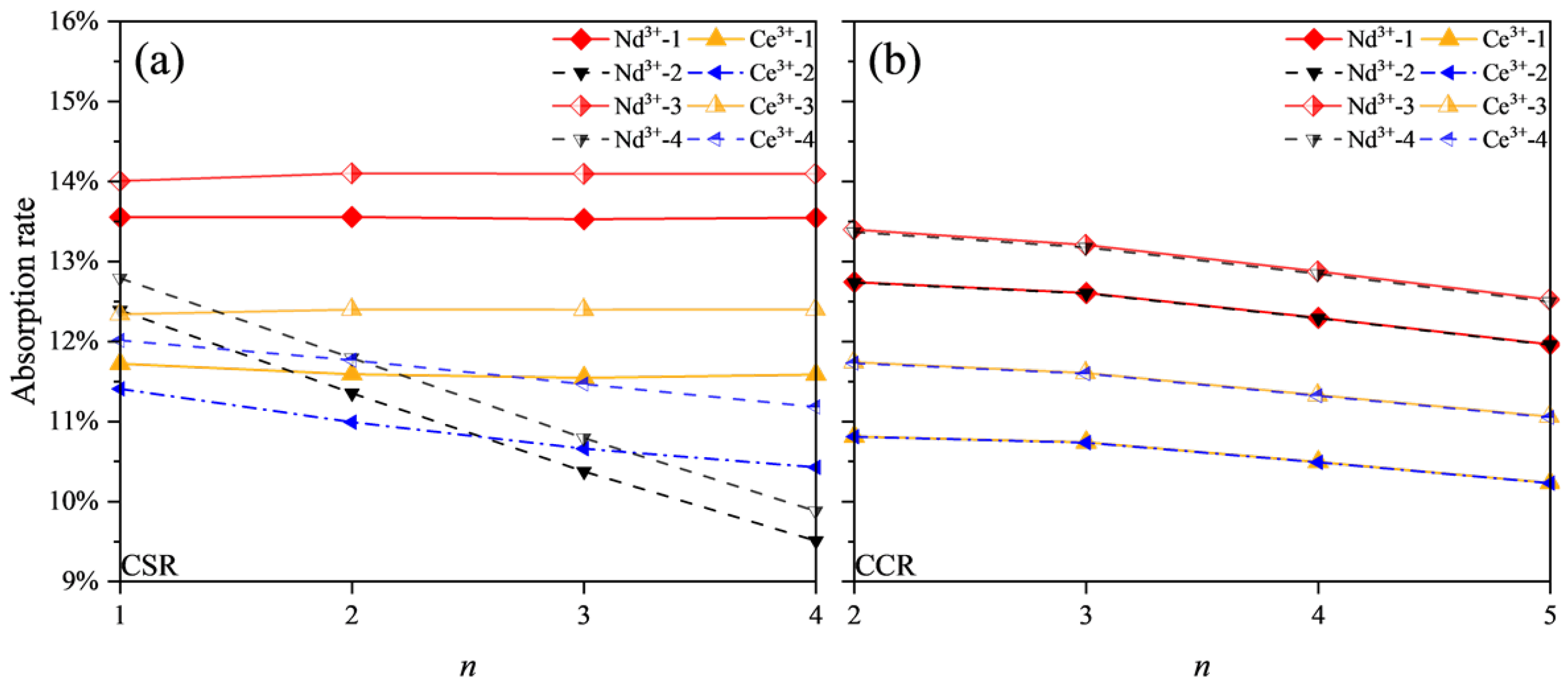
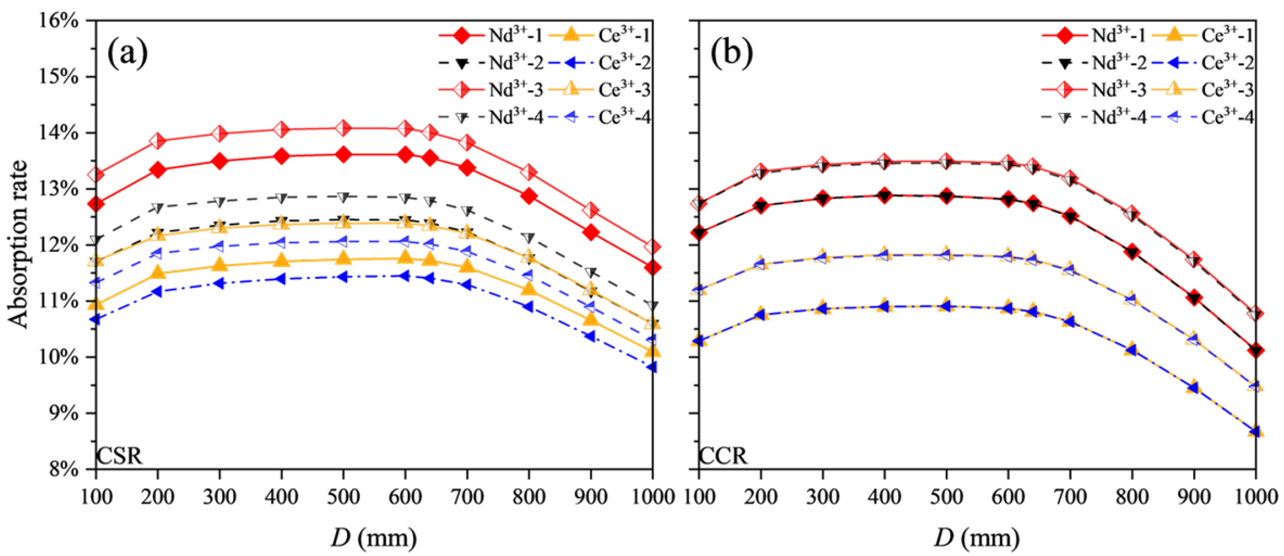
2.3. Calculation Results

Setting r m to 2 mm, r 0 to 5 mm, d to 2 mm, and l 0 to 5 mm, the objective is to determine the values of L and d 0 , where each value of L corresponds to a range of d 0 . Selecting four different focal lengths for the concentrator—200 mm, 500 mm, 800 mm, and 1000 mm—and using the relative aperture as a variable, we then calculate L at the corresponding critical γ , as illustrated in Figure 2 and Figure 3. The L values depicted in the figures are also applicable to concentrators with smaller apertures, which similarly satisfy the conditions for TIR; however, the incident angles of the marginal rays entering the laser medium remain less than the critical angle. Figure 2d and Figure 3d illustrate the distribution of L values when r m = 3 mm across a relative aperture range of 0.5 to 2, as well as the distribution of L values when r 0 = 6 mm within a relative aperture range of 0 to 2. Considering the comparisons with Figure 2 and the necessity of application, the values with higher reflection counts in Figure 3 have been rendered less prominent.
The results indicate that for the same relative aperture, shorter focal lengths facilitate the design of the conic reflector more effectively. When D is increased, r m is also correspondingly enlarged. Conversely, increasing r 0 necessitates a reduction in the size of the concentrator.
The number of reflections governs the angle at which light enters the laser medium. When the edge rays undergo n reflections, the central rays are reflected between 1 and n times. With each reduction in the number of reflections, the angle of incidence into the laser medium decreases by 2 θ , where θ is inversely related to n. As n increases, a greater amount of light enters the laser medium at angles approaching the critical angle.

2.4. TracePro Analysis

A concentrator with a focal length of 800 mm and a relative aperture of 0.8 was employed to investigate the effect of reflection count on solar light absorption. The simulation structure, shown in Figure 4, consists of a parabolic reflector with a silver-coated surface and a laser head filled with cooling water. The laser active medium is extended by 5 mm of pure YAG, serving as a mechanical holder for the crystal and effectively lowering the temperature in the clamping area. The CSR is bonded to the laser medium, with the CSR’s exit aperture aligned with the front face of the medium.
The simulated light source employs solar radiation under the AM1.5 standard, with an irradiance of 950 W/m 2 and a divergence angle of 0.54° [23], as shown in Figure 5. Two light sources were configured based on the absorption characteristics of Ce (0.05% at.):Nd (1% at.):YAG. And the doping concentrations of the crystal were selected based on insights gained from our previous experiments [20]. Light source 1 spans from 320 nm to 367 nm and from 400 nm to 515 nm for Ce 3 + absorption, while light source 2 covers 515 nm to 540 nm, 565 nm to 595 nm, 735 nm to 765 nm, 795 nm to 825 nm, and 855 nm to 885 nm for Nd 3 + absorption [20,24]. Nd 3 + ions account for approximately 16% of total solar energy, and Ce 3 + ions account for 15.3%. The light sources were calibrated to maintain these proportions without altering the spectral distribution.
The laser medium length is set at 20 mm, with parameter L derived from Figure 2 and Figure 3. The laser heads are positioned at the center of the d 0 . The effects of the coating on laser materials and YAG absorption are compared across four conditions, namely, condition 1 (no coating, no absorption), condition 2 (no coating, with absorption), condition 3 (coating, no absorption), and condition 4 (coating, with absorption). In conditions 3 and 4, an anti-reflective coating is applied to the incident end, and a dielectric reflective coating to the exit end, using data from Thorlabs’s anti-reflective coating (AB coating [25]) and reflective coating (E02 coating, 45°, unpolarized [26]). All fused silica windows are coated with the AB anti-reflective coating. The YAG absorption characteristics are based on the absorption coefficient of Ce:Nd:YAG, focusing on values below 0.02 cm 2 [27]. The remaining data are fitted via TracePro 7.3.4, potentially leading to an overestimation of the YAG absorption coefficient.
The results depicted in Figure 6 indicate that in conditions 1 and 3, sunlight transmits through the CSR with minimal loss. The absorption rate illustrates how the number of reflections affects the laser medium’s absorption; it nearly saturates when reflections reach two or more. Considering absorption, while CSR losses increase with additional reflections, CCR experiences minimal impact from YAG absorption, primarily losing energy due to the silver film’s reflection. Water absorption was considered in the simulation, but had a considerably lesser effect compared to the silver film.
Subsequent simulations were conducted using the CSR structure with n = 1 and the CCR structure with n = 2 . By varying the laser head position, the absorption efficiencies of sunlight by Nd 3 + ions and Ce 3 + ions are illustrated in Figure 7. The CSR structure exhibits d 0 ranging from −8.05 mm to −7.6 mm, while the CCR structure demonstrates d 0 between −8.05 mm and −7.45 mm. For comparison, the midpoint of these ranges is offset at position 0, with negative values indicating a shift toward the concentrator and positive values indicating an opposite shift. Results show that the central position consistently achieves higher absorption efficiency, with the CCR structure demonstrating greater robustness to positive shifts.
The absorption results for the laser medium, obtained from simulations varying the parameter D, are shown in Figure 8. Here, the focal length is also 800 mm. At a diameter of 100 mm, the efficiency is relatively low because a significant amount of light directly strikes the end face of the laser medium. In the range of 200 mm to 640 mm, the absorption efficiency stabilizes, peaking at 500 mm. These results indicate that there is a greater range of D sizes that enables a good absorption rate. Beyond 640 mm, efficiency declines sharply as edge light fails to satisfy TIR conditions. These simulation results align closely with the calculated data.

3. TIRSPL

3.1. Theory of Laser

The output power calculation formula for the Nd:YAG laser, characterized by its four-level energy system, is as follows [28]:
P OUT = A I S 1 R 1 + R 2 η B η Q η S P ab ( 2 α M l + L M ln R ) A I S 1
In the equation, A and l denote the cross-sectional area and length of the laser medium, respectively. R indicates the reflectivity of the output mirror, while α M is the scattering loss coefficient of the laser medium, set at 0.002 cm 1 [28]. I S represents the saturation power density of the gain medium, which is measured at 2888 W/m 2 [28]. The parameters η Q and η S represent the quantum efficiency and Stokes factor, respectively, and η B signifies the beam overlap efficiency. Finally, L M refers to other losses primarily arising from the transmission and reflection at the end faces of the laser medium [19]. Based on the measurements of existing Ce:Nd:YAG crystals, the reflectivity of the HR 1064 coating exceeds 99.95%, while the reflectivity of the AR 1064 coating is below 0.1%. Consequently, L M is approximately 0.0025.
The laser energy produced by Ce:Nd:YAG originates from the absorption of Ce 3 + ions and Nd 3 + ions. Approximately 71% of the pump energy absorbed by Ce 3 + ions is converted through non-radiative energy transfer to the upper laser level of Nd 3 + ions, while about 29% contributes to fluorescence in the 500–720 nm range, further pumping Nd 3 + ions [14,15]. Accurately assessing the radiative transfer component is challenging because the luminous intensity distribution depends on the absorption of Ce 3 + ions. Nonetheless, studies indicate that the overall energy transfer efficiency from Ce 3 + ions to Nd 3 + ions is approximately 76% [16], suggesting that P ab can be rewritten as
P ab = P ab Nd + η Q Ce - overall η S Ce η Q η S P ab Ce
The parameter η Q Ce - overall represents the overall energy transfer efficiency from Ce 3 + ions to Nd 3 + ions. Thus, P ab can be integrated into the ALSD model to compute the power output of Ce:Nd:YAG based on the Nd:YAG computational framework.
The Stokes factor for Ce 3 + ions requires recalculation using the weighted method based on Nd 3 + ions [29]. The weighted wavelength of the Ce 3 + ion absorption spectrum is approximately 450 nm, yielding a Stokes factor of 0.423. In contrast, the quantum efficiency of Nd 3 + ions at the pumping wavelength is around 95% [28], with a Stokes factor of approximately 0.62 [29].
In TracePro, absorption data for Ce 3 + ions and Nd 3 + ions are obtained using light sources 1 and 2, respectively. For thermal effect analysis, light source 3 is configured to cover the non-pumping spectral range of 300 nm to 900 nm. Wavelengths above 900 nm are ignored because of the weak absorption properties of the YAG substrate.
The radius of the laser medium has already been optimized to the current ideal dimensions; however, the length of the laser medium remains subject to further enhancement. A concentrator with a diameter of 600 mm is selected, providing an effective area of 0.2824 m 2 . Once the dimensions of the conic reflector are established, the distribution of absorbed energy with respect to the length becomes largely predetermined. Therefore, the evaluation encompasses laser medium lengths of 20 mm and 40 mm to ascertain their respective energy distributions, as illustrated in Figure 9. The curves are designated using the format “length- ions for absorption- condition number”.
The solid line represents the area-normalized energy distribution on the left axis, while the dashed line, shown on the right axis, depicts its integral. This enables us to derive the relationships f Nd ( l ) and f Ce ( l ) relating rod length to absorbed energy. These relationships act as proportional coefficients, which can be substituted into Equation (23) to produce the results:
P ab = P ab Nd f Nd ( l ) + η Q Ce - overall η S Ce η Q η S P ab Ce f Ce ( l )

3.2. ALSD Simulation
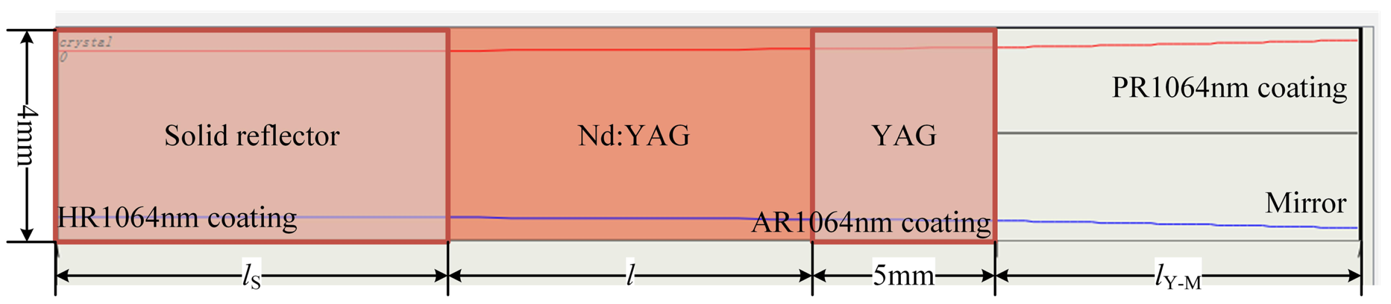
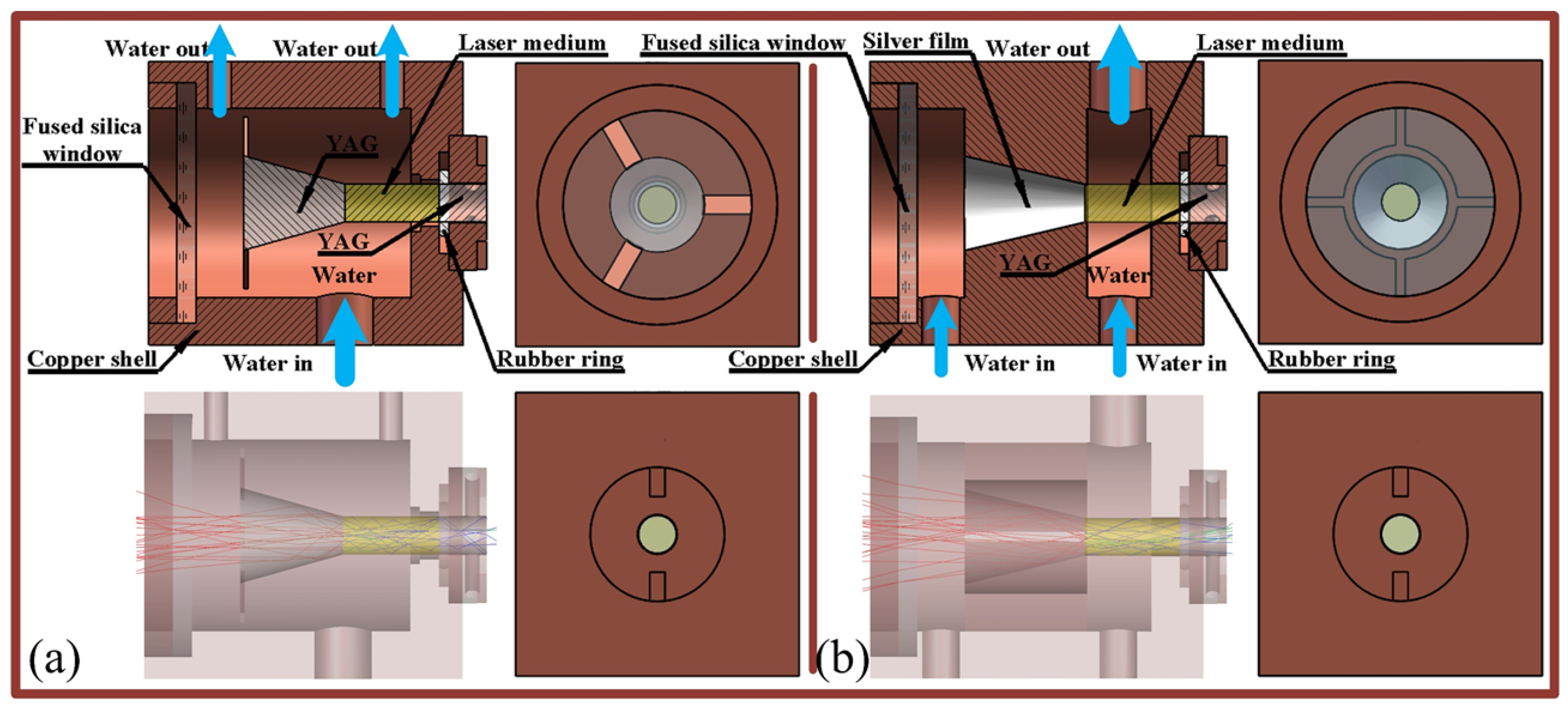
The arrangement of laser materials from left to right consists of a solid reflector (YAG), the laser medium (Nd:YAG), and an additional YAG layer, as shown in Figure 10. Here, l S indicates the length of the CSR, l refers to the length of the laser medium, and l Y - M is the distance from the rear surface of the YAG to the mirror.
In the CSR configuration, HR 1064 nm coating is applied to the front surface of the reflector, while the coating is placed on the front surface of the laser medium for the CCR, where l S = 0 . The rear surface of the YAG is treated with an AR coating for 1064 nm, while the mirror features a PR layer at the same wavelength. The quantum efficiency of the laser medium is also set at 0.95, with a stimulated emission cross-section of 2.8 × 10 17 mm 2 . Beam overlap is automatically calculated by ALSD.
The anticipated relationship between laser power and rod length, as derived from calculations, is illustrated by the curve in Figure 11. It is noteworthy that the laser output power attains its maximum value at approximately 10 mm. Absorption data for l values of 5 mm, 8 mm, 10 mm, 12 mm, 14 mm, and 20 mm were imported into ALSD 5.6 software to extract the maximum output power, as shown by the scatter points in Figure 11. The curves are designated using the format “length- laser medium- condition number”, while the scatter points are designated with the format “laser medium- condition number (ALSD)”. According to Ref. [28], the value of η B falls within the approximate range of 0.8 to 0.9. In the calculations, a beam overlap coefficient, η B , of 0.875 was employed, resulting in findings that are consistent with the simulated results for the 20 mm Nd:YAG laser medium without coating illustrated in Figure 11a. The CCR structure demonstrates low pump energy yet achieves high laser power, reflecting effective beam overlap. In contrast, the simulated power output for the 20 mm Ce:Nd:YAG is lower than the calculated values, indicating a diminished beam overlap compared to Nd:YAG. As the length of the laser medium decreases, simulation values show significant variation, primarily due to rear surface reflection and the enhanced beam overlap in shorter rods.
As the length of the laser medium increases from 5 mm to 20 mm, the output power ratio of Ce:Nd:YAG to Nd:YAG rises from 1.6 to 1.7, which aligns closely with the previous experimental data of 1.57 [17]. This further corroborates the validity of the computational results.

3.3. Structure

The mechanical structure of the laser head may obstruct sunlight, due to its positioning on the side of the parabolic reflector nearest to the light source. Additionally, the regions of the structure that interface with the laser medium can significantly affect the TIR of sunlight within that medium. Therefore, it is essential to design distinct mechanical structures for both the CSR and CCR to investigate the laser output characteristics and thermal distribution, as illustrated in Figure 12a,b. Their outer casings are made of copper, incorporating a water cooling system and rubber seals for effective sealing. The length of the laser medium was established at 10 mm. In Figure 12a, the structural dimensions are 30 mm × 30 mm × 35.75 mm, while in Figure 12b, the dimensions are 30 mm × 30 mm × 37.77 mm.
The effective area of the silver-coated concentrator is 0.2818 m 2 . The incident power from light source 1 to the concentrator is measured at 40.86 W, with a resulting focused power of 37.70 W, yielding a concentration efficiency of 92.27%. In contrast, light source 2 exhibits an incident power of 42.61 W and achieves a focused power of 41.55 W, culminating in a concentration efficiency of 97.52%. And the concentration efficiency across the entire AM1.5 spectrum is approximately 96.03%.

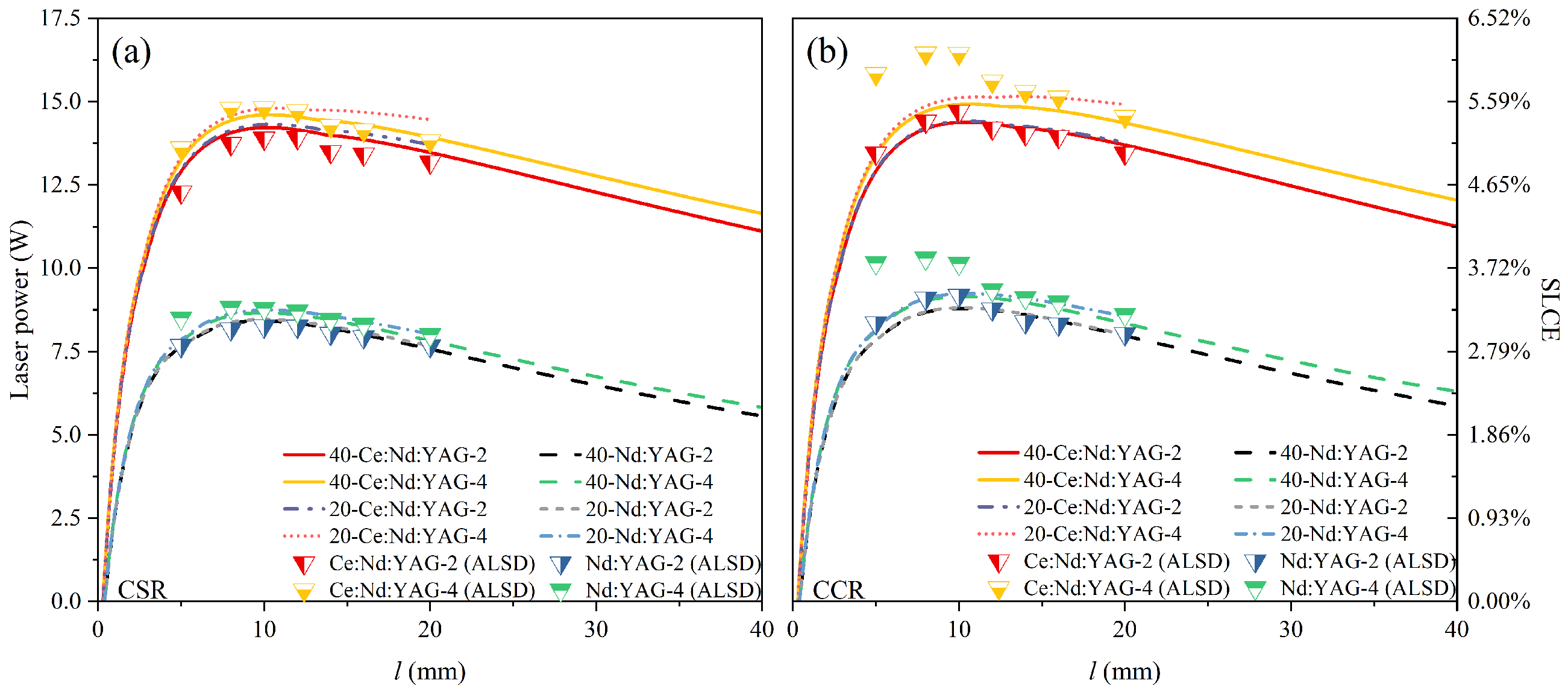
3.4. Model Comparison
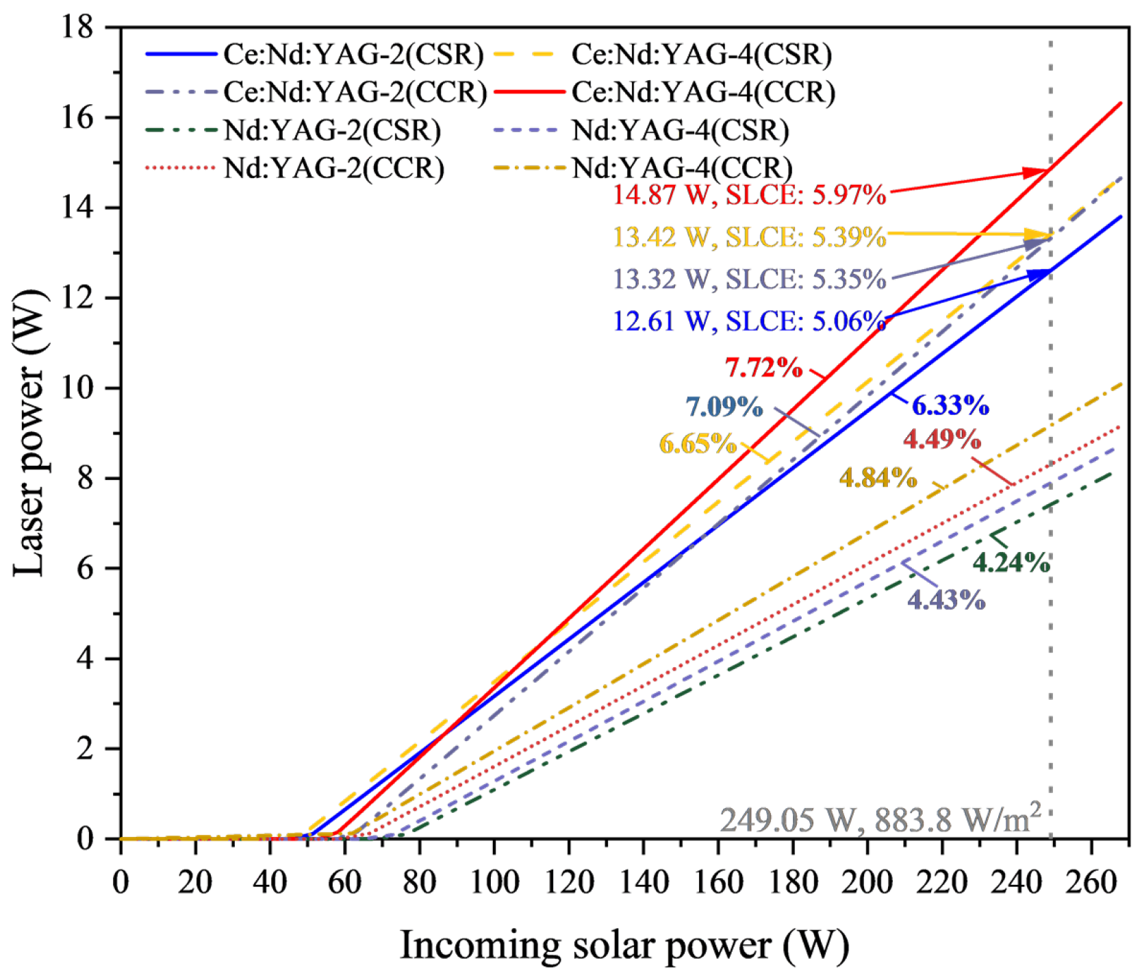
To assess the validity of the simulations and analyze potential discrepancies, a comparative study was conducted with several pieces of literature that present both experimental results and simulation data, similarly utilizing parabolic mirrors for light concentration.
Initially, a comparison is made regarding the variability in the absorption spectra of Ce:Nd:YAG. Another Ce:Nd:YAG absorption spectra (from Ref. [19]) is established for comparative analysis. Utilizing the same light source to simulate the CSR structure in condition 4, it was noted that the original absorption spectrum revealed an enhancement of 0.78 W in the absorption power of Nd 3 + ions, while the absorption power of Ce 3 + ions decreased by 3.12 W, indicating a relatively minor discrepancy.
Subsequently, an examination was conducted on the absorptive capacities of the laser mediums. The absorption efficiency of the laser medium is evaluated using the ratio of the pump energy per unit volume (with the denominator being the pump light energy at the focal position). Before and after coating, the absorption efficiencies for the CSR structure are 6.44 × 10 3 mm 3 and 6.71 × 10 3 mm 3 , respectively. For the CCR structure, the efficiencies are recorded as 6.38 × 10 3 mm 3 and 6.80 × 10 3 mm 3 . All values are notably higher than the simulated data reported in Ref. [18] (approximately 4.25 × 10 3 mm 3 ) and Ref. [19] (approximately 1.95 × 10 3 mm 3 ).
Finally, drawing upon the volumetric flux data outlined in Ref. [18], a comparative analysis was conducted to assess the differences in laser output results simulated via the LASCAD 3.6.6 and ALSD 5.6 software. According to the configuration methodology outlined in this study for the ALSD 5.6 software, a laser output of 11.14 W can be achieved. In contrast, the laser output reported in Ref. [18], which utilizes LASCAD 3.6.6 software, is 11.3 W.
The structure delineated in this study, characterized by its enhanced absorption capacity of the laser medium, demonstrates an improved capacity for laser generation, particularly when the differences between the absorption spectrum and the ALSD simulation are minimal. This effectively substantiates the validity of the simulations presented in this paper.

3.5. Laser Output

The maximum laser output power has been recalculated, showing that for the CSR structure, the laser output powers before and after coating are 13.80 W and 14.67 W, respectively, with SLCE values of 5.15% and 5.48%. For the CCR structure, the corresponding output powers are 14.65 W and 16.32 W, with efficiencies of 5.47% and 6.09%. The variable l Y - M is set at 1 mm, the output mirror reflectivity is 0.97, and the radius of the mirrors is 100 mm.
The slope efficiency curves illustrated in Figure 13 indicate that for the CSR structure of Ce:Nd:YAG, the slope efficiencies are 6.33% and 6.65% before and after coating, with threshold values of 51.37 W and 48.68 W. The CCR structure shows slope efficiencies of 7.09% and 7.72%, with thresholds of 63.23 W and 58.14 W. The coating significantly reduces the pumping threshold of the laser medium while enhancing slope efficiency. It is important to note that Nd:YAG has a higher pumping threshold and lower slope efficiency compared to Ce:Nd:YAG.
The thermal distribution in TIRSPL is complex, complicating the accurate determination of the M 2 factor. Considering only the pump energy, the M 2 values are 190 for the CSR structure and 330 for the CCR structure. With the l Y - M set at 10 mm, a mirror with a 1000 mm radius of curvature can reduce the M 2 factor of the CSR structure to approximately 65, while a radius of curvature 2000 mm can lower the M 2 factor of the CCR structure to around 80. Furthermore, laser power fluctuations are maintained below 0.01 W.

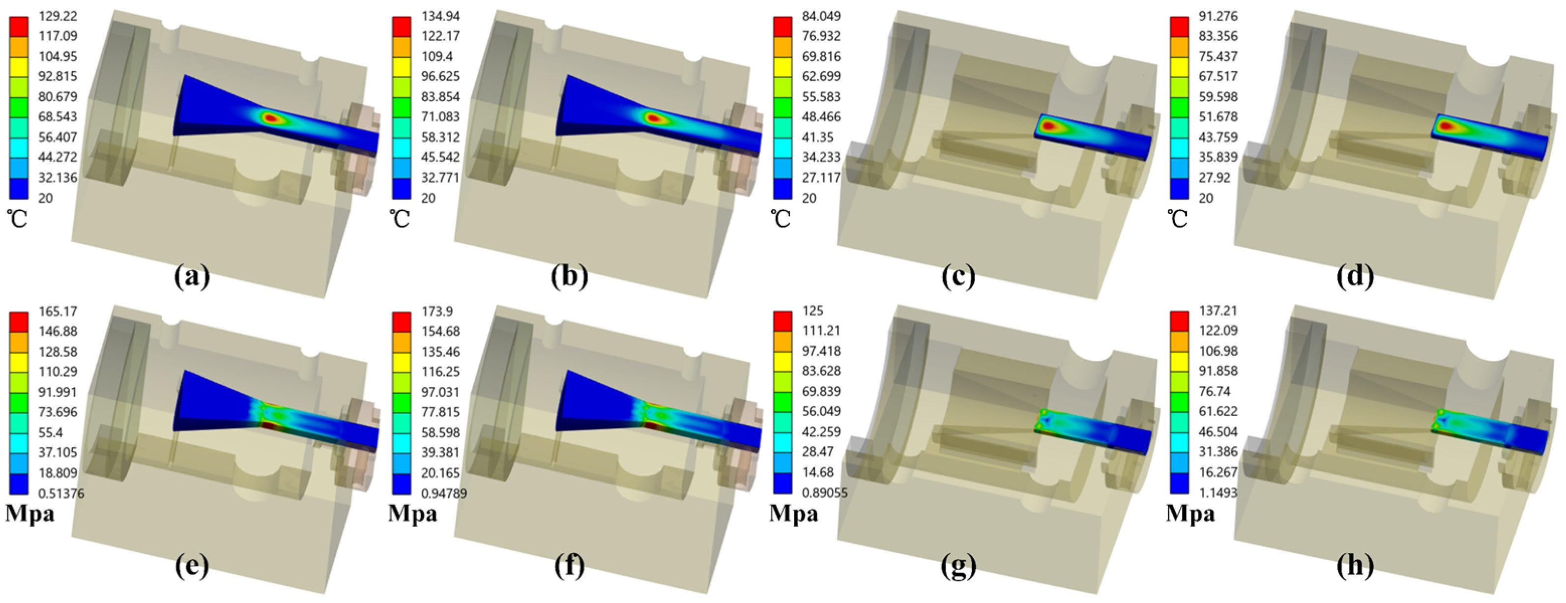
3.6. Thermal Analysis

A synergistic methodology was implemented, integrating ALSD 5.6 and ANSYS 2024 R2 to facilitate a thorough thermal analysis, as ALSD alone is insufficient for accurately calculating the thermal distribution within the CSR structure. Within the ALSD software, the optical-to-thermal conversion efficiency is calibrated to derive thermal distributions influenced by various light sources. Notably, the photothermal efficiency of Ce 3 + under light source 1 is adjusted to be 1.65 times that of Nd 3 + ions under light source 2. In the case of light source 3, all absorbed energy is entirely devoted to thermal energy generation. These thermal distributions are then superimposed and imported into ANSYS 2024 R2 for an in-depth thermal and stress analysis. Given the compact dimensions of the laser head and the rapid circulation of cooling water, it is assumed that the cooling water maintains a constant temperature of 20 °C, while the ambient temperature is set at 22 °C. To account for potential worst-case scenarios, the irradiance utilized in the thermal analysis is set at 1000 W/m 2 .
As depicted in Figure 14, the CSR structure achieves a maximum temperature of approximately 130 °C, with pre-coating maximum stress at 165.17 MPa, increasing to 173.9 MPa post-coating, both of which remain below the YAG substrate laser medium’s tensile stress limit of 200 MPa [28,30]. Conversely, the CCR structure reaches a peak temperature of around 90 °C, with maximum stresses of 125 MPa and 137.21 MPa before and after coating, respectively.
The TIR structure effectively absorbs solar radiation but also heightens the absorption of non-essential wavelengths, resulting in substantial heat generation. For large-aperture lasers, it is crucial to design the fused silica windows with filters that minimize the intake of unnecessary solar light. While the coating process is relatively straightforward due to the compact size of the laser head, the design of the filtering membrane system requires thorough investigation.

4. Discussion

The TIRSPL system modulates the angle of concentrated sunlight via the conic reflector structure, coupling it into the laser medium to enable TIR. This increases the transmission path length and enhances absorption. TracePro 7.3.4 is employed for the analysis of light transmission and absorption, while ALSD 5.6 software is utilized to simulate laser output. Additionally, a combination of ALSD 5.6 and ANSYS 2024 R2 is applied to assess temperature and stress.
The results indicate that when the effective area of the parabolic concentrator is 0.2818 m 2 and the solar irradiance is 950 W/m 2 , the CSR structure without coatings achieves a maximum laser output of 13.80 W, with a slope efficiency of 6.33% and an SLCE of 5.15%. After coating, the maximum laser output power increases to 14.67 W, with a slope efficiency of 6.65% and an SLCE of 5.48%. For the CCR structure, the maximum laser output power values before and after coating are 14.65 W and 16.32 W, respectively, with slope efficiencies of 7.09% and 7.72%, and SLCE values of 5.47% and 6.09%.
The comparison between this study and previous research is illustrated in Table 1. In contrast to the studies conducted by Liang [19] and Costa [21], the TIRSPLs are capable of achieving higher output in the form of a single rod, even under conditions of relatively low incoming solar power. Currently, the highest SLCE achieved by a single laser medium stands at 4.50% with incoming solar power of 249.05 W [18]. Under the same incident solar power, the CSR structure demonstrates SLCE values that are 1.12 and 1.20 times greater, while the CCR structure achieves efficiencies that are 1.19 and 1.33 times greater, as illustrated in Figure 13. These results clearly illustrate that the TIRSPL is a more efficient SPL system.
Thermal analysis results indicate that TIRSPL exhibits significant sunlight absorption capabilities, resulting in higher heat generation. The CSR structure suffers from inadequate cooling effects at the front face of the laser medium and lacks compatibility with larger concentrators, making the CCR structure more suitable in this context. Targeted coatings based on the pumping spectrum, along with the elimination of non-essential wavelength bands, are instrumental in facilitating the output of high-power lasers from the TIRSPL in the future. However, the polished surface of the laser medium may encourage the formation of parasitic oscillations; therefore, it is essential to apply an AR coating to the end face of the YAG, and designing the face with a specific angled slope will further mitigate this issue [28]. Through simulations conducted with TracePro 7.3.4 software, it has been determined that an angle of approximately 4° for the inclined surface can effectively suppress parasitic oscillations. This approach represents a promising avenue for future enhancements of the structure.
The design of the concentrator for the TIRSPL is more flexible, enabling similar solar energy absorption effects across a broad range of dimensions. Moreover, the optimal placement of the laser head falls within a defined range, where minor positional adjustments exert a negligible impact on laser output. In terms of the design of the laser rod length, the TIRSPL demonstrates enhanced predictability and a more streamlined design process compared to traditional end-side pumping systems.
Moreover, in comparison to the CCR system, the fabrication of the CSR system presents certain manufacturing challenges, primarily stemming from the production of the CSR itself rather than the bonding of the two planes. Although some difficulties exist, the technology for shaping optical glass into conical lenses is relatively advanced [31]. By analogy, the processing of the CSR system is not expected to pose significant technical obstacles. This CCR structure allows for a relatively fixed positioning of the reflector in relation to the laser medium, making alignment straightforward. The TIR process in this setup incurs negligible losses, with the primary losses arising from the absorption of light by the material itself. Conversely, the CCR is easier to manufacture but requires high precision in alignment, with losses primarily originating from mirror surface reflections and the absorption by the filling materials of the cavity.

5. Conclusions

High efficiency is a key objective in the development of solar-pumped lasers. An innovative design for an end-face pumped SPL system is presented in this study, anchored in the principles of TIR. By utilizing a conical reflector, sunlight is effectively coupled into the polished laser rod at angles conducive to total internal reflection. This methodology enhances the transmission pathway of the pump light through TIR, thereby promoting the absorption of sunlight by the laser medium. Ultimately, this approach aims to significantly improve the SLCE.
In the numerical simulations, a specially designed conical solid reflector or conical cavity reflector is employed in the system. This configuration effectively couples sunlight, focused by a parabolic mirror with an effective area of 0.2818 m 2 and a focal length of 800 mm, into a Ce:Nd:YAG laser medium with a diameter of 4 mm and a length of 10 mm. All pump light is successfully transmitted through TIR within the laser medium.
Through a meticulous integration of theoretical calculations and simulations utilizing TracePro 7.3.4 and ALSD 5.6 software software, a comprehensive analysis of the conical reflector design was conducted. This assessment encompassed the effects of reflection counts, the positioning of the laser head, the dimensions of the concentrator, the size of the laser medium, and the output power of the SPL. Furthermore, ANSYS 2024 R2 was employed to simulate the thermal and stress distributions within the laser material.
The final results demonstrate that the SLCE values of the CSR structure before and after coating are 5.15% and 5.48%, respectively, at a solar irradiance of 950 W/m 2 . Meanwhile, the SLCE values of the CCR structure before and after coating are 5.47% and 6.09%, respectively. These findings clearly indicate a significant enhancement in SLCE within the framework of the TIRSPL system.

Author Contributions

Conceptualization, L.W.; methodology, L.W.; validation, L.W. and D.G.; formal analysis, L.W., H.Z. and C.Z.; investigation, L.W., D.G. and W.X.; resources, H.Z. and C.Z.; data curation, A.G.; writing—original draft preparation, L.W.; writing—review and editing, D.G. and H.Z.; visualization, L.W. and W.X.; supervision, H.Z. and C.Z.; project administration, H.Z. and C.Z.; funding acquisition, C.Z. All authors have read and agreed to the published version of the manuscript.

Funding

This research was funded by the National Natural Science Foundation of China, grant numbers 61378020 and 61775018.

Data Availability Statement

Data are contained within the article.

Conflicts of Interest

The authors declare no conflicts of interest. The funders had no role in the design of the study; in the collection, analyses, or interpretation of data; in the writing of the manuscript; or in the decision to publish the results.

References

  1. Guan, Z.; Zhao, C.M.; Yang, S.H.; Wang, Y.; Ke, J.Y.; Zhang, H.Y. Demonstration of a Free-Space Optical Communication System Using a Solar-Pumped Laser as Signal Transmitter. Laser Phys. Lett. 2017, 14, 055804. [Google Scholar] [CrossRef]
  2. Mori, M.; Kagawa, H.; Saito, Y. Summary of Studies on Space Solar Power Systems of Japan Aerospace Exploration Agency (JAXA). Acta Astronaut. 2006, 59, 132–138. [Google Scholar] [CrossRef]
  3. Takeda, Y.; Iizuka, H.; Mizuno, S.; Hasegawa, K.; Ichikawa, T.; Ito, H.; Kajino, T.; Ichiki, A.; Motohiro, T. Silicon Photovoltaic Cells Coupled with Solar-Pumped Fiber Lasers Emitting at 1064 Nm. J. Appl. Phys. 2014, 116, 014501. [Google Scholar] [CrossRef]
  4. Kiss, Z.J.; Lewis, H.R.; Duncan, R.C. Sun Pumped Continuous Optical Maser. Appl. Phys. Lett. 1963, 2, 93–94. [Google Scholar] [CrossRef]
  5. Young, C.G. A Sun-Pumped Cw One-Watt Laser. Appl. Opt. 1966, 5, 993–997. [Google Scholar] [CrossRef]
  6. Lando, M.; Kagan, J.; Linyekin, B.; Dobrusin, V. A Solar-Pumped Nd:YAG Laser in the High Collection Efficiency Regime. Opt. Commun. 2003, 222, 371–381. [Google Scholar] [CrossRef]
  7. Yabe, T.; Ohkubo, T.; Uchida, S.; Yoshida, K.; Nakatsuka, M.; Funatsu, T.; Mabuti, A.; Oyama, A.; Nakagawa, K.; Oishi, T.; et al. High-Efficiency and Economical Solar-Energy-Pumped Laser with Fresnel Lens and Chromium Codoped Laser Medium. Appl. Phys. Lett. 2007, 90, 261120. [Google Scholar] [CrossRef]
  8. Liang, D.; Almeida, J. Highly Efficient Solar-Pumped Nd:YAG Laser. Opt. Express 2011, 19, 26399–26405. [Google Scholar] [CrossRef]
  9. Dinh, T.H.; Ohkubo, T.; Yabe, T.; Kuboyama, H. 120 watt continuous wave solar-pumped laser with a liquid light-guide lens and an Nd:YAG rod. Opt. Lett. 2012, 37, 2670. [Google Scholar] [CrossRef]
  10. Liang, D.; Almeida, J.; Vistas, C.R.; Guillot, E. Solar-Pumped Nd:YAG Laser with 31.5 W/M2 Multimode and 7.9 W/M2 TEM00-Mode Collection Efficiencies. Sol. Energy Mater. Sol. Cells 2017, 159, 435–439. [Google Scholar] [CrossRef]
  11. Liang, D.; Vistas, C.R.; Tibúrcio, B.D.; Almeida, J. Solar-Pumped Cr:Nd:YAG Ceramic Laser with 6.7% Slope Efficiency. Sol. Energy Mater. Sol. Cells 2018, 185, 75–79. [Google Scholar] [CrossRef]
  12. Guan, Z.; Zhao, C.; Li, J.; He, D.; Zhang, H. 32.1 W/M2 Continuous Wave Solar-Pumped Laser with a Bonding Nd:YAG/YAG Rod and a Fresnel Lens. Opt. Laser Technol. 2018, 107, 158–161. [Google Scholar] [CrossRef]
  13. Vistas, C.R.; Liang, D.; Garcia, D.; Almeida, J.; Tibúrcio, B.D.; Guillot, E. Ce:Nd:YAG Continuous-Wave Solar-Pumped Laser. Optik 2020, 207, 163795. [Google Scholar] [CrossRef]
  14. Yamaga, M.; Oda, Y.; Uno, H.; Hasegawa, K.; Ito, H.; Mizuno, S. Energy transfer from Ce to Nd in Y3Al5O12 ceramics. In Proceedings of the Physica Status Solidi C: Current Topics in Solid State Physics; Naito, H., Tanabe, S., Eds.; John Wiley & Sons, Inc.: Hoboken, NJ, USA, 2012; Volume 9, pp. 2300–2303. [Google Scholar] [CrossRef]
  15. Tai, Y.; Zheng, G.; Wang, H.; Bai, J. Near-infrared quantum cutting of Ce3+–Nd3+ co-doped Y3Al5O12 crystal for crystalline silicon solar cells. J. Photochem. Photobiol. A Chem. 2015, 303–304, 80–85. [Google Scholar] [CrossRef]
  16. Payziyev, S.; Sherniyozov, A.; Bakhramov, S.; Zikrillayev, K.; Khalikov, G.; Makhmudov, K.; Ismailov, M.; Payziyeva, D. Luminescence sensitization properties of Ce:Nd:YAG materials for solar pumped lasers. Opt. Commun. 2021, 499, 127283. [Google Scholar] [CrossRef]
  17. Vistas, C.R.; Liang, D.; Almeida, J.; Tibúrcio, B.D.; Garcia, D.; Catela, M.; Costa, H.; Guillot, E. Ce:Nd:YAG Side-Pumped Solar Laser. J. Photonics Energy 2021, 11, 018001. [Google Scholar] [CrossRef]
  18. Garcia, D.; Liang, D.; Vistas, C.R.; Costa, H.; Catela, M.; Tiburcio, B.D.; Almeida, J. Ce:Nd:YAG Solar Laser with 4.5% Solar-to-Laser Conversion Efficiency. Energies 2022, 15, 5292. [Google Scholar] [CrossRef]
  19. Liang, D.; Vistas, C.R.; Gracia, D.; Tiburcio, B.D.; Catela, M.; Costa, H.; Guillot, E.; Almeida, J. Most Efficient Simultaneous Solar Laser Emissions from Three Ce:Nd:YAG Rods within a Single Pump Cavity. Sol. Energy Mater. Sol. Cells 2022, 246, 111921. [Google Scholar] [CrossRef]
  20. Cai, Z.; Zhao, C.; Zhao, Z.; Zhang, J.; Zhang, Z.; Zhang, H. Efficient 38.8 W/m2 solar pumped laser with a Ce:Nd:YAG crystal and a Fresnel lens. Opt. Express 2023, 31, 1340–1353. [Google Scholar] [CrossRef]
  21. Costa, H.; Liang, D.; Almeida, J.; Tiburcio, B.D.; Vistas, C.R. Four-Ce:Nd:YAG-rod Solar Laser with 4.49% Conversion Efficiency through Fresnel Lens. Sci. Rep. 2025, 15, 13354. [Google Scholar] [CrossRef]
  22. Mizuno, S.; Ito, H.; Hasegawa, K.; Suzuki, T.; Ohishi, Y. Laser Emission from a Solar-Pumped Fiber. Opt. Express 2012, 20, 5891–5895. [Google Scholar] [CrossRef]
  23. ASTM G173-03(2012); Tables for Reference Solar Spectral Irradiances: Direct Normal and Hemispherical on 37 Tilted Surface. ASTM: West Conshohocken, PA, USA, 2012. [CrossRef]
  24. Samuel, P.; Yanagitani, T.; Yagi, H.; Nakao, H.; Ueda, K.I.; Babu, S.M. Efficient energy transfer between Ce3+ and Nd3+ in cerium codoped Nd: YAG laser quality transparent ceramics. J. Alloys Compd. 2010, 507, 475–478. [Google Scholar] [CrossRef]
  25. AB AR Coating Data. Available online: https://www.thorlabs.com/newgrouppage9.cfm?objectgroup_id=12767&pn=AC127-019-AB#12796 (accessed on 22 July 2025).
  26. E02 Reflection Data. Available online: https://www.thorlabs.com/newgrouppage9.cfm?objectgroup_id=139&pn=BB03-E02#11967 (accessed on 22 July 2025).
  27. Slack, G.A.; Oliver, D.W.; Chrenko, R.M.; Roberts, S. Optical Absorption of Y3Al5O12 from 10- to 55000- cm−1 Wave Numbers. Phys. Rev. 1969, 177, 1308–1314. [Google Scholar] [CrossRef]
  28. Koechner, W. Solid-State Laser Engineering; Springer: Berlin/Heidelberg, Germany, 2006. [Google Scholar] [CrossRef]
  29. Weksler, M.; Shwartz, J. Solar-Pumped Solid-State Lasers. IEEE J. Quantum Electron. 1988, 24, 1222–1228. [Google Scholar] [CrossRef]
  30. Liang, D.; Almeida, J.; Vistas, C.; Tibúrcio, B.; Garcia, D. Solar-Pumped Lasers: With Examples of Numerical Analysis of Solid-State Lasers; Green Energy and Technology; Springer: Berlin/Heidelberg, Germany, 2023. [Google Scholar] [CrossRef]
  31. Axicon Lenses. Available online: https://www.thorlabs.com/newgrouppage9.cfm?objectgroup_id=16616 (accessed on 22 July 2025).
Figure 1. Schematic representation of the structure of the conical reflector.
Energies 18 04033 g001
Figure 2. The relationship between L and relative aperture for the CSR at critical γ . (a) The focal length is 200 mm. (b) The focal length is 500 mm. (c) The focal length is 800 mm. (d) The focal length is 1000 mm.
Energies 18 04033 g002
Figure 3. The relationship between L and relative aperture for the CCR at critical γ . (a) The focal length is 200 mm. (b) The focal length is 500 mm. (c) The focal length is 800 mm. (d) The focal length is 1000 mm.
Energies 18 04033 g003
Figure 4. The structure of TIRSPL in TracePro. (a) Concentrating structure. (b) Laser structure for the CSR. (c) Laser structure for the CCR.
Energies 18 04033 g004
Figure 5. AM1.5 spectrum and simulation light source configuration.
Energies 18 04033 g005
Figure 6. The relationship between n and the solar energy absorption efficiency. (a) In the CSR. (b) In the CCR.
Energies 18 04033 g006
Figure 7. The solar absorption efficiency of sunlight at different positions of the laser head. (a) In the CSR. (b) In the CCR.
Energies 18 04033 g007
Figure 8. The solar absorption efficiency of sunlight at different concentrator sizes. (a) In the CSR. (b) In the CCR.
Energies 18 04033 g008
Figure 9. Distribution of absorbed energy in the laser medium from TracePro. (a) In the CSR. (b) In the CCR.
Energies 18 04033 g009
Figure 10. Laser resonant cavity in ALSD.
Energies 18 04033 g010
Figure 11. The relationship between laser output power and the length of the laser medium under 950 W/m 2 solar irradiance. (a) In the CSR. (b) In the CCR.
Energies 18 04033 g011
Figure 12. The structure of the laser head. (a) CSR laser head. (b) CCR laser head.
Energies 18 04033 g012
Figure 13. Slope efficiency of TIRSPL.
Energies 18 04033 g013
Figure 14. (a) The temperature for the CSR structure in condition 2. (b) The temperature for the CSR structure in condition 4. (c) The temperature for the CCR structure in condition 2. (d) The temperature for the CCR structure in condition 4. (e) The stress for the CSR structure in condition 2. (f) The stress for the CSR structure in condition 4. (g) The stress for the CCR structure in condition 2. (h) The stress for the CCR structure in condition 4.
Energies 18 04033 g014
Table 1. Comparison of SPLs based on Ce:Nd:YAG crystal.
ParameterGarcia (2022) [18]Liang (2022) [19]Costa (2025) [21]The CSR StructureThe CCR Structure
ConcentratorParabolic mirrorParabolic mirrorFresnel lensParabolic mirrorParabolic mirror
Effective area ( m 2 )0.2930.40.6170.28180.2818
Irradiance ( W/m 2 )850890860950950
Number of laser medium13411
Laser power (W)11.216.522.4614.6716.32
Incoming solar power (W)249.05356530267.71267.71
Collection efficiency ( W/m 2 )38.2241.2536.452.0357.9
SLCE4.50%4.64%4.49%5.48%6.09%
Slope efficiency6.80%7.64%6.33%6.65%7.72%
Disclaimer/Publisher’s Note: The statements, opinions and data contained in all publications are solely those of the individual author(s) and contributor(s) and not of MDPI and/or the editor(s). MDPI and/or the editor(s) disclaim responsibility for any injury to people or property resulting from any ideas, methods, instructions or products referred to in the content.

