Article

Improved Segmented Control Strategy for Continuous Fault Ride-Through of Doubly-Fed Wind Turbines

1
College of Electrical and New Energy, China Three Gorges University, Yichang 443002, China
2
Hubei Provincial Key Laboratory for Operation and Control of Cascaded Hydropower Station, China Three Gorges University, Yichang 443002, China
*
Author to whom correspondence should be addressed.
Energies 2025, 18(14), 3845; https://doi.org/10.3390/en18143845 (registering DOI)
Submission received: 1 July 2025 / Revised: 16 July 2025 / Accepted: 17 July 2025 / Published: 19 July 2025

Abstract

Aiming at the transient overcurrent problem faced by doubly-fed induction generators (DFIGs) during continuous voltage fault ride-through, a segmented control strategy based on the rotor side converter (RSC) is proposed. First, through theoretical analysis of the relationship between stator current and transient induced electromotive force (EMF) in each stage of continuous faults, a feedforward control strategy based on the transient component of stator current is proposed. The observable stator current is extracted for its transient component, which is used as a rotor voltage compensation term to effectively counteract the influence of transient EMF. Meanwhile, a fuzzy control algorithm is introduced during the low voltage ride-through (LVRT) stage to dynamically adjust the virtual resistance value, enhancing the system’s damping characteristics. Studies show that this strategy significantly suppresses rotor current spikes in all stages of voltage ride-through. Finally, simulation results verify that the proposed method improves the ride-through performance of DFIG under continuous voltage faults.

1. Introduction

Doubly-fed induction generators (DFIGs) are widely used in the wind power sector [1,2,3,4]. To ensure grid stability, wind turbines must possess low-voltage ride-through (LVRT), high-voltage ride-through (HVRT), and continuous fault ride-through capabilities. Compared with single voltage faults, continuous voltage faults are characterized by “low-high voltage continuous outages,” with longer durations and more severe disconnection consequences [5]. The current research focus is on optimizing the control strategy of the rotor side converter (RSC) to ensure that doubly-fed wind turbines do not disconnect during continuous fault ride-through.
Ensuring that wind turbines do not disconnect during faults is the key to solving continuous fault ride-throughs. Current solutions include two approaches: hardware measures and software measures. Hardware measures include crowbars [6,7,8], rotor-side DC choppers [9], energy storage systems (ESS) [10,11], stator-side dynamic voltage regulators (DVRs) [12], etc., but adding hardware increases costs. Software measures optimize the operation control strategy of wind turbines, and this paper adopts software measures.
The stator winding of DFIG is directly connected to the grid. When the grid voltage undergoes abrupt changes, the stator flux linkage generates transient variations, inducing significant transient electromotive force (EMF) in the rotor. If the amplitude exceeds the critical threshold, it triggers severe rotor transient overcurrent, causing wind turbine disconnection accidents. Literature [13] uses stator flux linkage as a basis to derive the relationship between stator flux linkage and free components of EMF, adding the derivative of stator flux linkage to the rotor current loop to suppress transient EMF. Literature [14] proposes a simple disturbance feedforward control method to eliminate EMF disturbances and compensate for current errors, achieving zero-error current tracking. Literature [15] uses the dynamic change of stator equivalent excitation current as a rotor voltage compensation term, offsetting EMF through the output voltage of RSC to enhance the transient response of DFIG during HVRT. Literature [16] introduces a flux linkage loop to quickly attenuate stator transient flux linkage oscillation control delay. Literature [17] proposes a classic demagnetization control method to fully counteract EMF. Literature [18,19,20] suggests superimposing reactive power control commands on demagnetization current commands, introducing virtual inductance to reduce current demand, and optimizing demagnetization control coefficients. However, the above strategies require stator flux linkage observation and phase sequence separation, leading to significant engineering implementation difficulties. The need for flux linkage observation and separation makes physical realization tedious and less adaptable. Therefore, seeking a simpler and more adaptable method to obtain transient EMF is essential.
Virtual resistors/impedances can effectively suppress rotor current spikes and oscillations at the moment of fault. Literature [21] indicates that doubly-fed wind turbines have underdamped characteristics, and the rotor-side damping ratio increases proportionally with rotor resistance. Introducing virtual resistors enhances system damping. Literature [22] proposes a virtual impedance control method to reduce rotor current oscillations through coordinated operation of high- and low-frequency bands.
Both types of strategies mentioned above increase rotor voltage requirements. The required rotor voltage may exceed the converter’s rated capacity, leading to current loop saturation and loss of controllability. Additionally, the above research focuses on single faults, and their adaptability during continuous faults requires further verification.
Current research on continuous fault ride-through mainly focuses on fault mechanism analysis, with fewer studies on control strategies. Literature [23] analyzes the transient characteristics of low- and high-voltage faults and finds that a high-voltage fault of 1.3 times the rated voltage and a low-voltage fault of 0.7 times the rated voltage exhibit similar transient characteristics. Literature [24] discovers that during continuous fault ride-through, the transient characteristics of the low-voltage stage significantly affect the high-voltage stage. Literature [25] reveals through theoretical derivation the mutual influencing factors among each stage of continuous ride-through, indicating that its transient process is more complex and intense than single faults.
Based on this, this paper proposes a segmented control strategy based on RSC, which switches working modes by real-time voltage status detection through RSC. First, starting from the transient characteristics of continuous fault ride-through, the expressions of stator current and transient EMF in each stage are theoretically analyzed, and a feedforward control strategy based on the transient component of stator current is proposed. The observable stator current realizes rotor voltage compensation to suppress rotor overcurrent. Secondly, a fuzzy control algorithm is introduced in the low-voltage stage to dynamically adjust the virtual resistance value, which collaborates with the feedforward control for optimization to enhance the damping characteristics of the system. Furthermore, the LVRT control strategy improves HVRT performance, significantly enhancing the ride-through capability of DFIG under continuous voltage faults. Finally, a simulation model is built to verify that the proposed strategy improves the ride-through performance of DFIG under continuous voltage faults.

2. Analysis of the Principle of Continuous Voltage Ride-Through in Wind Farms

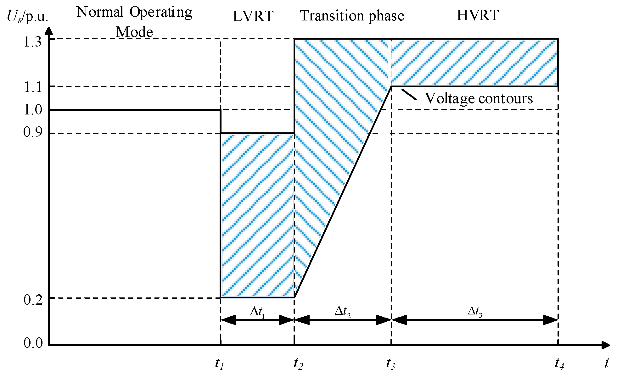
2.1. Requirements for Wind Farm Voltage Continuous Ride-Through

Figure 1 reflects the requirements for wind power continuous fault ride-through [26], which includes three stages: LVRT ( Δ t 1 ), transition ( Δ t 2 ), and HVRT ( Δ t 3 ). The voltage of the wind turbine needs to remain within the specified voltage profile range in all three stages to achieve a fast and stable transition from LVRT to HVRT.
Δ t 1 with Δ t 3 should comply with the requirements of the wind farm during LVRT and HVRT, and since the convergence of zero is the worst-case scenario that the turbine needs to cope with for continuous crossing of wind turbines, Δ t 2 is considered to be zero.

2.2. Transient Modeling of Doubly-Fed Wind Turbines

The wind turbine model uses the motor convention. After converting the motor parameters to the stator side, the rotor voltage of the DFIG in the rotor rotating coordinate system can be expressed as [27,28]:
U ˙ r r = L m L s d d t ψ ˙ s r + ( R r + σ L r d d t ) I ˙ r r
E ˙ r r = L m L s d d t ψ ˙ s r
where: the superscript “ r ” denotes the rotor coordinate system; the subscripts “ s ” and “ r ” denote the stator and rotor, respectively; U ˙ r r is the rotor voltage; I ˙ r r is the rotor current; R r is the rotor resistance; L s , L r , and L m represent the stator winding inductance, rotor winding inductance, and mutual inductance between the stator and rotor windings, respectively; E r r is the rotor transient induced EMF; σ = 1 L m 2 / L s L r .
Thus, the vector equivalent circuit of the rotor side of DFIG in the rotor coordinate system is shown in Figure 2, where the dashed frame indicates the virtual resistance added during the LVRT stage in Section 2.2. The rotor transient inductance σ L r and rotor resistance R r depend on the hardware structure or parameters of the wind turbine itself. When the hardware structure and parameters of DFIG remain unchanged, the rotor current magnitude is determined by the difference between the rotor voltage and transient EMF.
Feedforward compensation of the rotor voltage and increasing the damping of the rotor circuit are effective ways to suppress the rotor current. Through feed-forward compensation, the rotor voltage generates a control voltage that is inverse to the EMF, thus weakening the transient-induced electromotive force; increasing the equivalent resistance on the rotor side reduces the rotor impedance voltage drop between U ˙ r r and E r r .
Under the same abrupt change amplitude, the transient characteristics of single voltage swell/dip faults are highly similar [23], and the core of fault ride-through lies in suppressing rotor overcurrent. The voltage during the LVRT stage may dip to 0.2 p.u., while the swell during the HVRT stage usually does not exceed 1.3 p.u. [26], with significantly different abrupt change amplitudes, so the transient characteristics of the two stages differ. Compared with HVRT, the LVRT stage has a larger abrupt change amplitude, and the rotor overcurrent problem is more severe. Continuous voltage ride-through faces the dual challenges of LVRT and HVRT. Different from single voltage faults, the low voltage stage in continuous faults affects the high voltage stage. Improving the transient characteristics of the low-voltage stage can also enhance the transient characteristics of the high-voltage stage.
Feedforward compensation is limited by RSC capacity. During deep faults in the low voltage stage of continuous ride-through, relying solely on transient EMF compensation makes it difficult to completely eliminate rotor current spikes, while virtual resistance control can further reduce transient current spikes. Therefore, consider the combination of both within the converter capacity to achieve dual suppression.

3. Control Strategy

3.1. Design Principle of Feed-Forward Based on Stator Current Transient Component

3.1.1. Continuous Ride-Through Transient Characteristics

Assuming that the grid voltage at t 0 moments of symmetrical drop faults, the depth of voltage drop is h 1 , t 1 moments of fault removal and due to excess reactive power voltage surge, voltage surge amplitude of h 2 , t 2 moments of the grid voltage to return to normal values, U s is the amplitude of the stator voltage during steady-state operation, and the grid voltage is:
U ˙ s r = U s e j ω 1 t , t < t 0 1 h 1 U s e j ω 1 t , t 0 t < t 1 1 + h 2 U s e j ω 1 t , t 1 t < t 2 U s e j ω 1 t , t 2 t
According to the fact that the stator flux linkage cannot change suddenly at the moment of the fault, the expressions of the stator flux linkage and the rotor transient induced EMF under continuous faults are [25]:
ψ ˙ s r = ψ ˙ sf r + ψ ˙ sn r = D e j ω 1 t , t < 0 1 h 1 D e j ω 1 t + h 1 A e t τ s , 0 t < t 1 1 + h 2 D e j ω 1 t + D L H 1 e t τ s , t 1 t < t 2 D e j ω 1 t + D L H 1 + H 2 e t τ s , t 2 t
where: D = U s / ( j ω 1 + 1 / τ s ) ; H 1 = d 2 e j ω r + 1 / τ s t 1 ; H 2 = d 2 e j ω r + 1 / τ s t 2
E ˙ r r = E ˙ rf r + E ˙ r n r = V s e j ω slip t , t < t 0 V s s 1 h 1 e j ω slip t V s ( 1 s ) h 1 e j ω r + 1 τ s t , t 0 t < t 1 V s s 1 + h 2 e j ω slip t + V s ( 1 s ) H 1 e j ω r + 1 τ s t G E , t 1 t < t 2 V s s e j ω s slip t + V s ( 1 s ) H 1 H 2 e j ω r + 1 τ s t G E , t 2 t
G E = h 1 1 e j ω s + 1 / τ s t 1 j ω r + 1 / τ s t
where: V s = U s L m / L s , τ s = L s / R s is the stator time constant.
Where, G E is the degree of influence of the low voltage stage on the high voltage stage. According to (6), it can be seen that the degree of dip of the low voltage stage h 1 and the duration Δ t affect the high voltage stage. The amplitude of G E increases with the increase of h 1 , and the smaller Δ t is, the shorter its decay time is, and the less influence it has on the high voltage stage. In addition, based on the circuit-switching theorem, the performance of the LVRT scheme will directly affect the transient characteristics of the high-voltage stage.
By deriving the transient component I sn of stator current in the rotor coordinate system and converting it to the synchronous speed rotating coordinate system:
I sn s = h 1 I s 1 e j ω 1 + 1 τ s t , t 0 t < t 1 I s 1 h 1 H e j ω 1 + 1 τ s t , t 1 t < t 2 I s 1 h 1 H + h 2 e j ω 1 + 1 τ s t 2 e j ω 1 + 1 τ s t , t 2 t
where the superscript “ s ” denotes the synchronous rotating coordinate system; I s 1 = U s / j ω 1 + 1 / τ s L s ; H = ( h 1 + h 2 ) e ( j ω 1 + 1 / τ s ) t 1 .
According to (5), it can be seen that the rotor transient induced EMF E ˙ r r consists of two parts, the steady state component E ˙ r f r and the transient component E ˙ r n r . The rotor transient induced EMF E ˙ r n r is converted to the synchronous speed rotation dq coordinate system and expressed as:
E rn s = U s L m L s ( 1 s ) h 1 e j ω 1 + 1 τ s t , t 0 t < t 1 U s L m L s ( 1 s ) h 1 H e j ω 1 + 1 τ s t , t 1 t < t 2 U s L m L s ( 1 s ) h 1 H + h 2 e j ω 1 + 1 τ s t s e j ω 1 + 1 τ s t , t 2 t
By dividing Equations (7) and (8), the rotor current transient component and stator current transient component satisfy:
E rn s = L m ( 1 s ) ( j ω + 1 τ s ) I s n s
The stator current I s s in the synchronous rotating coordinate system is:
I s s = I sn s + ( 1 -   h 1 ) I s 1 , t 0 t < t 1 ( 1 + h 2 ) I s 1 , t 1 t < t 2 I s 1 , t 2 t
Substituting Formula (10) into Formula (9):
E rn s = L m ( 1 s ) ( j ω + 1 τ s ) ( I s s ( 1 h 1 ) I s 1 , t 0 t < t 1 ( 1 + h 2 ) I s 1 , t 1 t < t 2 I s 1 , t 2 t )
During grid faults, when the slip ratio is constant and the excitation inductance of the wind turbine is fixed, only I s s is a variable in the right-side expression of the (11), with other parameters being constants. Therefore, by observing the stator current, its transient component can be obtained, providing an accurate basis for the feedforward control of the rotor converter. Based on this, the strategy can effectively respond to the dynamic changes in each stage of continuous faults, enhancing the ride-through performance of wind turbines throughout the fault process.

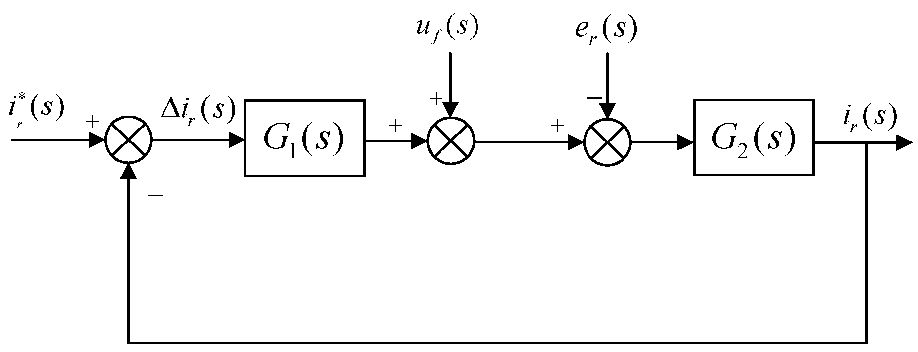
3.1.2. DFIG Rotor Current Loop

Under the traditional control, the block diagram of DFIG rotor-side current loop control is shown in Figure 3, where: i r ( s ) is the reference value of rotor current; u f ( s ) is the feed-forward term, which is usually designed as EMF; e r ( s ) is the perturbation term; G 1 ( s ) = K p + K i / s is the transfer function of the current regulator, i.e., the PI controller; and G 2 ( s ) = 1 / ( σ L r s + R r ) is the transfer function of the current closed-loop controlled object.
Combined with the previous analysis, there is a proportional relationship between the transient EMF and the stator current transient component. Using the EMF disturbance term as feedforward to counteract its disturbance, the control block diagram after introducing feedforward control is shown in Figure 4, where K f ( s ) is the disturbance feedforward function.

3.2. Control Strategy Based on Virtual Resistance

The selection of virtual resistance value is limited by converter capacity—a resistance value that is too small results in insufficient rotor current suppression during faults. Fuzzy control features strong adaptability, fast dynamic response, and high robustness [29]. Different from the fixed-resistance virtual resistance control strategy, this paper introduces fuzzy control theory during the LVRT stage to design a fuzzy adaptive control strategy.

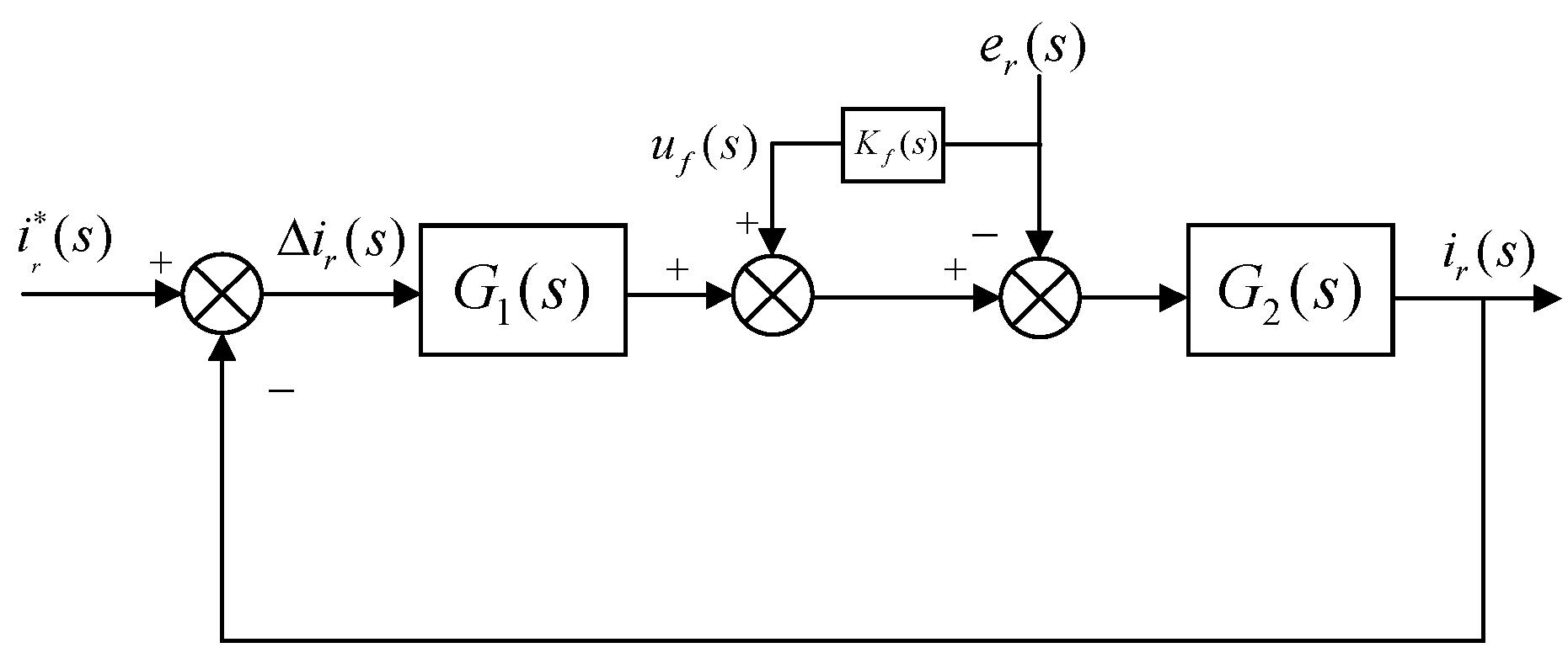
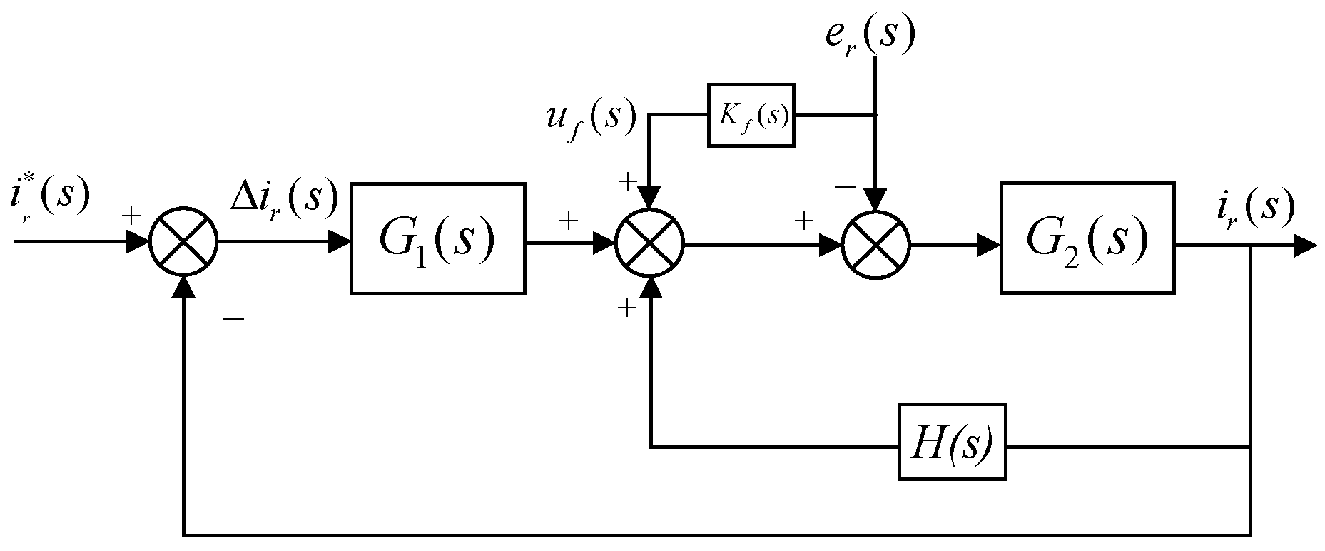
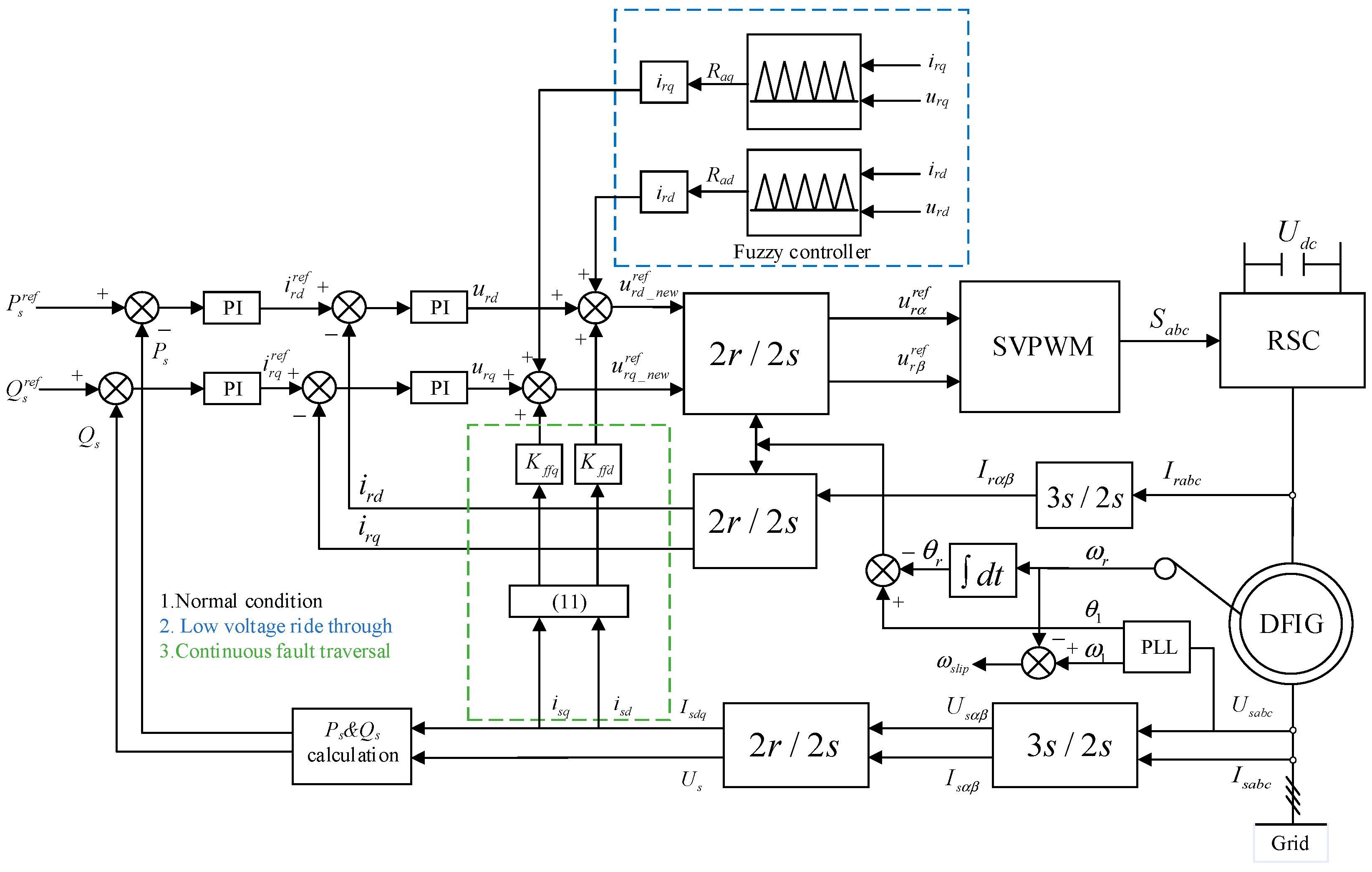
3.2.1. Control System Incorporating Feedforward and Virtual Resistance

The DFIG exhibits underdamping characteristics in its flux linkage dynamics [30], and the equivalent resistance of the rotor loop can be effectively increased through proportional feedback correction. After optimizing the feed-forward compensation term (rotor voltage) and the controlled object (virtual resistance), the control block diagram of its rotor current loop is shown in Figure 5.
Where H ( s ) = R a is the feedback link transfer function, the transfer function of the current closed-loop controlled object after adding the virtual resistance can be expressed as:
G 2 ( s ) = 1 σ L r s + ( R r + R a )
It can be seen from the above that the denominator adds the virtual resistance R a , equivalent to increasing the resistance in the rotor current loop to suppress the peak value of rotor current, as shown in the dashed frame of Figure 2. The following constraints need to be satisfied for the rotor voltage when the SVPWM modulation algorithm is used during a fault:
| U r s | < | U r max s | = U d c 2
where U d c is the rated voltage on the DC side.

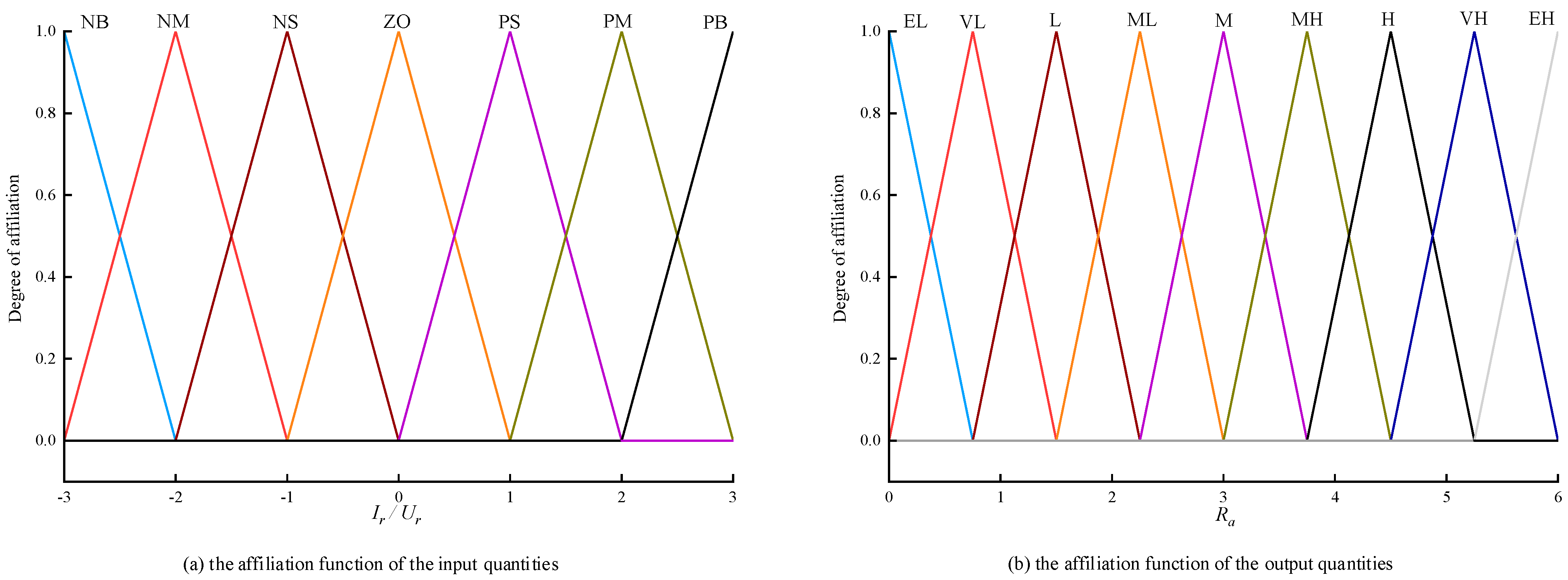
3.2.2. Design of Fuzzy Adaptive Link

In this article, a dual-input single-output fuzzy controller is used. The real-time status quantities of rotor current and rotor voltage in the synchronous rotating coordinate system are used as inputs to the fuzzy inference system, and the fuzzy controller generates a dynamically adjusted virtual resistance value, which is finally combined with the aforementioned feedforward compensation to output the rotor voltage compensation term.
The fuzzy subsets of input variables i r and u r are defined as {NB, NM, NS, ZO, PS, PM, PB}, and the fuzzy subsets of output variables R a are defined as {EL, VL, L, ML, M, MH, H, VH, EH}, with EL to EH increasing sequentially; the input variable domains are defined in [−3, 3], and the output volume domains are defined in [0, 6]. The membership functions of input and output quantities all use isosceles triangle functions with high sensitivity, as shown in Figure 6, to ensure control stability and response speed. The centroid method is used for defuzzification, balancing information from each membership point to obtain a smooth output characteristic [31].
In the low-voltage stage, coordinated control combining virtual resistance and feedforward compensation is adopted. If the rotor current is detected to exceed the safety threshold, the fuzzy controller outputs a virtual resistance with a large resistance value to quickly suppress the current peak (not exceeding twice the rated value). Meanwhile, the rotor voltage is monitored in real time. If the virtual resistance causes the voltage to approach the upper limit of the converter, the virtual resistance value is reduced to prevent the voltage from exceeding the limit. Based on this, the fuzzy rules of the fuzzy adaptive link are shown in Table 1.

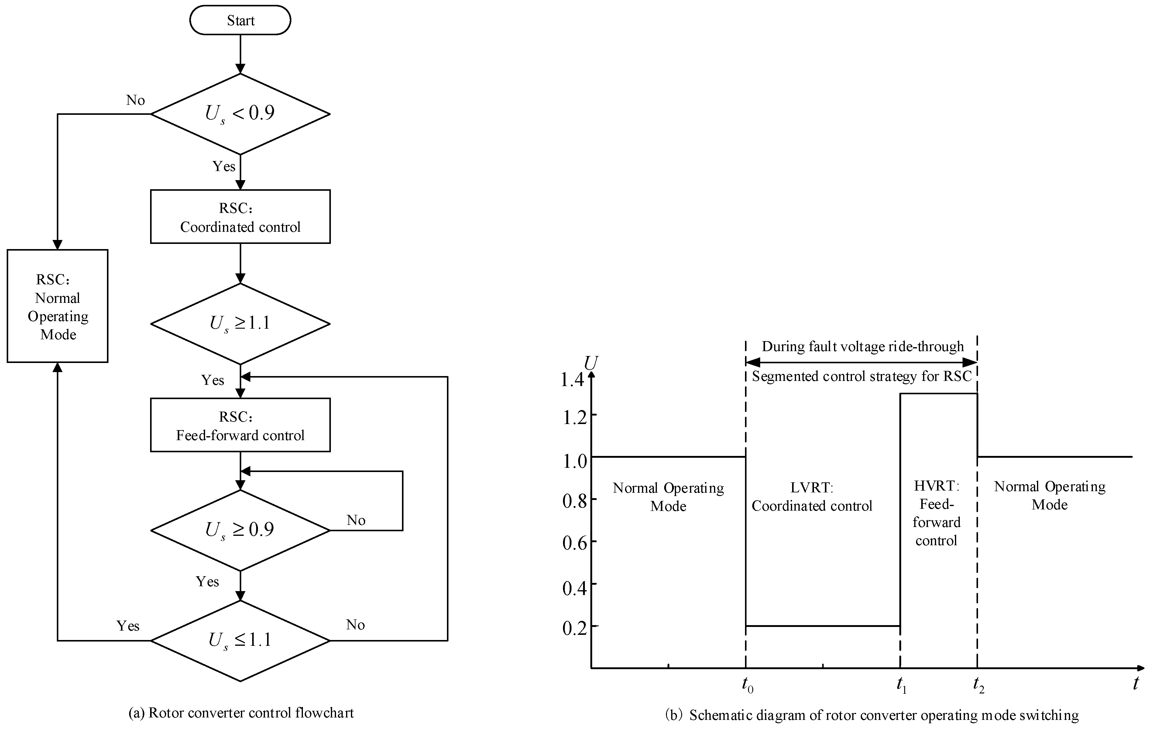
3.3. Segmented Control Strategy

The control block diagram of the segmented control strategy is shown in Figure 7, in which the dotted line box is the additional control link. P s r e f , Q s r e f are the reference value of stator output active and reactive power; P s , Q s are the actual value of stator output active and reactive power; i r d r e f , i r q r e f are the reference value of d and q components of rotor current; i r d , i r q are the actual value of d and q components of rotor current; I s a b c , I r a b c are the three-phase currents of stator and rotor; I s α β , I r α β are the currents of α and β components of stator and rotor; u r d _ n e w r e f , u r q _ n e w r e f are the new reference value of d and q components of rotor voltage; u r α r e f , u r β r e f are the voltages of d and q components of rotor voltage; U s a b c for the stator voltage; U s α β for α and β component of stator voltage; K f f d , K f f q for d and q axis feed-forward compensation coefficients. During continuous ride-through, the feedforward coefficients are set based on the HVRT stage, and the LVRT stage superimposes virtual resistance control on this basis; θ 1 , θ r for the spatial position angle between the d and α axes and the spatial position angle of the stator and the rotor; and S a b c for the three-phase component of the switching function.
Under steady-state operation, the DFIG achieves power decoupling control through synchronous dq-frame transformation. During continuous faults, the transient induced EMF component is calculated based on (11) by performing a dq coordinate transformation of the observable stator current. It is introduced as a compensation term in the rotor voltage reference to realize feed-forward compensation control. For enhanced LVRT performance, a fuzzy-controlled virtual resistance strategy is synergistically combined with the feed-forward compensation, establishing a coordinated control scheme.
As shown in Figure 8a, when the voltage is within the rated range ( U s 0.9   p . u . ), the RSC maintains the normal working mode. When a voltage drop ( U s < 0.9   p . u . ) is detected, the coordinated control strategy of feedforward compensation and virtual resistance is enabled, and the virtual resistance value is dynamically adjusted by the fuzzy controller. In the HVRT stage, the system exits the virtual resistance control and only uses feedforward compensation until the system returns to normal operation.
As shown in Figure 8b, considering the dynamic characteristics of voltage recovery, a delay detection window Δ t is set to confirm the state: if the grid voltage satisfies U s 1.1   p . u . within Δ t , it is judged to be normal recovery, and the system switches to normal working mode; if U s > 1.1   p . u . is detected, it is judged that a continuous fault occurs. When the HVRT phase ends, the system performs delay detection again: if the grid voltage continuously meets U s 1.1   p . u . and the maintenance time exceeds Δ t , it is judged that the chain fault is eliminated, and the control strategy automatically exits and switches to the normal operation mode.

4. Simulation Analysis

To verify the effectiveness of the proposed control strategy, a grid-connected simulation model of DFIG is constructed on the MATLAB/Simulink platform, in which the structure schematic and parameters are shown in Figure 9 and Table 2, respectively. Four comparative control strategies are designed:
(1) Traditional vector control strategy;
(2) Feed-forward control strategy based on stator current transient component;
(3) Virtual resistance control strategy based on fixed resistance value;
(4) Segmented control strategy based on RSC.
In the simulation, a three-phase short-circuit fault is set to occur at 0.2 s, and the fault duration is 0.1 s. After the fault is removed, a voltage surge occurs, and the surge duration is 0.05 s, and then the voltage at the grid point is restored to the normal value. To verify the effectiveness of the proposed control strategy, two voltage ride-through scenarios are set up in this paper: deep fault (voltage drops to 0.3 p.u. and surges to 1.3 p.u.) and mild fault (voltage drops to 0.7 p.u. and surges to 1.2 p.u.). During grid faults, the power-down operation ensures that the steady-state amplitudes of the stator and rotor currents remain constant before and after the fault, thus reducing the difficulty of the DFIG’s fault ride-through. At the same time, the DFIG provides reactive power support per system demand to assist fault ride-through realization.

4.1. Deep Fault

To verify the effectiveness of the strategies proposed in this article under deep faults, Figure 10 compares the simulation results of Strategy 1, Strategy 3, and Strategy 4 under continuous voltage faults with voltage dips of 0.3 p.u. to swells of 1.3 p.u. The results show that under strategy 1, the rotor current peaks at the beginning of the LVRT, reaching 2.83 p.u., and the DC bus voltage exceeds 2000 V, which is far beyond the safety threshold, and there is a risk of disconnection from the grid; although strategy 3 can partially suppress the rotor overcurrent and DC bus overvoltage, there is still the phenomenon of overrunning the limit. In contrast, the control strategy proposed in this article significantly improves the suppression effect: during voltage dips and surges, the peak rotor currents are reduced by 0.716 p.u. and 0.247 p.u. Compared with the traditional strategy, and by 0.248 p.u. and 0.063 p.u. Compared with strategy 3, the rotor currents are basically kept in the range of the threshold value, while the DC bus voltage is always kept within the safe operation range. In addition, Figure 10d, Comparison of the rotor voltage waveforms of strategies 3 and 4, shows that the fuzzy algorithm dynamic regulation can effectively limit the rotor voltage and prevent it from exceeding the threshold value.
It should be emphasized that the control strategy proposed in this article significantly reduces the peak value of the rotor current after the voltage swell, which indicates that the control method adopted in the LVRT stage effectively mitigates the transient shock caused by the voltage swell. The improved control strategy can effectively constrain the key ride-through indexes at all stages of chain faults, which is consistent with the theoretical analysis results. However, due to the RSC capacity limitation, the rotor current may still exceed the threshold value for a short time under severe faults. Therefore, although the strategy in this article can mitigate the impact of severe faults, it still needs to be combined with hardware ride-through measures to further expand the ride-through range.

4.2. Mild Fault

Figure 11 compares the simulation results of Strategy 1, Strategy 2, and Strategy 4 under continuous voltage faults with voltage dip 0.7 p.u. to swell 1.2 p.u. The results show that under mild faults, the control strategy in this article significantly outperforms the other strategies and is able to limit the peak rotor current to 1.846 p.u. (2 p.u. below the safety threshold) in the low-voltage stage and reduce the peak rotor current by 0.172 p.u. and 0.100 p.u. in the high-voltage stage compared to strategies 1 and 2, respectively, and at the same time stabilizes the dc-bus voltage to less than 1350 V, which is below the safety threshold. In contrast, Strategy 1 has overcurrent risk in the early stage of LVRT, and both rotor current and DC bus voltage exceed the safety threshold; Strategy 2 improves both rotor current and DC bus point voltage compared with Strategy 1, which verifies that the stator current transient component accurately reflects the transient induced EMF, i.e., the validity of feed-forward control, but there is still an overcurrent risk in the early stage of LVRT, and it can not satisfy the fault ride-through requirement. The experimental results prove that the strategy proposed in this article can effectively suppress the rotor current inrush and the DC bus overvoltage under continuous voltage faults, meeting the safety requirements for the fault ride-through of the DFIG.

5. Conclusions

In this paper, for the grid voltage continuous fault ride-through transient behavior, through theoretical analysis of stator current and transient induced electromotive force characteristics, a feed-forward control strategy based on the stator current transient component is proposed, and a virtual resistance is introduced in the low voltage stage, combined with the fuzzy control to dynamically regulate the resistance value, which synergistically forms a rotor converter segmentation control strategy with the feed-forward control. The conclusions are as follows:
(1) The relationship equation between stator current and transient induced electromotive force of a doubly-fed wind turbine is theoretically derived, and the stator current can be directly obtained to extract the transient component as a feed-forward compensation term to suppress rotor overcurrent, which is more conducive to the implementation of the project.
(2) In the LVRT stage of continuous fault, the coordinated control of feed-forward compensation and virtual resistance is adopted; in the HVRT stage, feed-forward control is adopted, which can effectively reduce the peak value of transient current and enhance the fault ride-through capability.
(3) Under the limitation of converter capacity, the fuzzy control algorithm is used to dynamically adjust the virtual resistance to follow the dynamic changes in faults, which ensures that the rotor current and voltage are in a safe range.
(4) The proposed strategy can improve the continuous fault ride-through performance under both light and deep faults, but it still needs to be combined with hardware protection measures or explore the synergistic optimization of software and hardware protection to complement the strengths and weaknesses under deep voltage dips, which provides a direction for the future development of fault ride-through technology.

Author Contributions

Methodology, T.C. and Y.X.; Software, Y.L. and J.R.; Validation, Y.F. and Y.X.; Writing—original draft, Y.X.; writing—review and editing, T.C. All authors have read and agreed to the published version of the manuscript.

Funding

This research was supported by the National Natural Science Foundation of China (51907104), The Opening Fund of Hubei Province Key Laboratory of Operation, and Control of Cascade Hydropower Station (2019KJX08).

Data Availability Statement

The original contributions presented in the study are included in the article, further inquiries can be directed to the corresponding author.

Conflicts of Interest

The authors declare no conflicts of interest.

References

  1. Li, W.; Chao, P.; Liang, X.; Ma, J.; Xu, D.; Jin, X. A practical equivalent method for DFIG wind farms. IEEE Trans. Sustain. Energy 2017, 9, 610–620. [Google Scholar] [CrossRef]
  2. Liu, X.; Li, C.; Shahidehpour, M.; Chen, X.; Yi, J.; Wu, Q.; Sun, K.; Zhou, B. Fault current mitigation and voltage support provision by microgrids with synchronous generators. IEEE Trans. Smart Grid 2020, 11, 2816–2831. [Google Scholar] [CrossRef]
  3. Zhou, C.; Wang, Z.; Xin, H.; Ju, P. A PQ coordination based model predictive control for DFIG high-voltage ride through. IEEE Trans. Energy Convers. 2021, 37, 254–263. [Google Scholar] [CrossRef]
  4. Maheshwari, Z.; Kengne, K.; Bhat, O. A comprehensive review on wind turbine emulators. Renew. Sustain. Energy Rev. 2023, 180, 113297. [Google Scholar] [CrossRef]
  5. Tian, S.; Chen, W.; Wang, P. Continuous voltage ride-through segmentation control strategy for PMSG-based wind power integrated systems with dynamic reactive current scale factor. Proc. Chin. Soc. Electr. Eng. 2024, 44, 7671–7684. [Google Scholar]
  6. Onishi, K.; Li, Y.; Koiwa, K.; Liu, F.; Zanma, T.; Liu, K.-Z. Analysis on the operation of crowbar in doubly fed induction generators. Electr. Power Syst. Res. 2023, 215, 108950. [Google Scholar] [CrossRef]
  7. Xiao, F.; Xia, Y.; Zhang, K.; Zhang, Z.; Yin, X. Fault characteristics analysis of DFIGWT in whole LVRT process considering control strategy switching between RSC and Crowbar. Int. J. Electr. Power Energy Syst. 2023, 145, 108615. [Google Scholar] [CrossRef]
  8. Ali, M.A.S. Improved Transient Performance of a DFIG-Based Wind-Power System Using the Combined Control of Active Crowbars. Electricity 2023, 4, 320–335. [Google Scholar] [CrossRef]
  9. Wei, J.; Li, C.; Wu, Q.; Zhou, B.; Xu, D.; Huang, S. MPC-based DC-link voltage control for enhanced high-voltage ride-through of offshore DFIG wind turbine. Int. J. Electr. Power Energy Syst. 2021, 126, 106591. [Google Scholar] [CrossRef]
  10. Lai, J.; Liu, Y.; Yin, X.; Wang, Y.; Hu, J.; Yin, X.; Zhou, K. A novel hybrid interlinking transformer-integrated DFIG wind power and energy storage system with flexible control strategy. Int. J. Electr. Power Energy Syst. 2025, 168, 110641. [Google Scholar] [CrossRef]
  11. Tabosa da Silva, P.L.; Rosas, P.A.C.; Castro, J.F.C.; Marques, D.d.C.; Aquino, R.R.B.; Rissi, G.F.; Neto, R.C.; Barbosa, D.C.P. Power Smoothing Strategy for Wind Generation Based on Fuzzy Control Strategy with Battery Energy Storage System. Energies 2023, 16, 6017. [Google Scholar] [CrossRef]
  12. Ahmed, M.; Kandil, T.; Ahmed, E. Enhancing Doubly Fed Induction Generator Low-Voltage Ride-through Capability Using Dynamic Voltage Restorer with Adaptive Noise Cancellation Technique. Sustainability 2022, 14, 859. [Google Scholar] [CrossRef]
  13. Rafiee, Z.; Heydari, R.; Rafiee, M.; Aghamohammadi, M.R.; Blaabjerg, F. Enhancement of the LVRT capability for DFIG-based wind farms based on short-circuit capacity. IEEE Syst. J. 2022, 16, 3237–3248. [Google Scholar] [CrossRef]
  14. Zhu, D.; Zou, X.; Dong, W.; Jiang, C.; Kang, Y. Disturbance feedforward control for type-3 wind turbines to achieve accurate implementation of transient control targets during LVRT. Int. J. Electr. Power Energy Syst. 2020, 119, 105954. [Google Scholar] [CrossRef]
  15. Sun, L.; Wang, Y. Analysis and performance evaluation for transient whole process of improved control strategy for doubly-fed induction generator during high voltage ride-through. High Volt. Eng. 2019, 45, 593–599. [Google Scholar]
  16. Zhu, R.; Chen, Z.; Tang, Y.; Deng, F.; Wu, X. Dual-loop control strategy for DFIG-based wind turbines under grid voltage disturbances. IEEE Trans. Power Electron. 2015, 31, 2239–2253. [Google Scholar] [CrossRef]
  17. Xiang, D.; Ran, L.; Tavner, P.J.; Yang, S. Control of a doubly fed induction generator in a wind turbine during grid fault ride-through. IEEE Trans. Energy Convers. 2006, 21, 652–662. [Google Scholar] [CrossRef]
  18. Shen, Y.W.; Ke, D.P.; Qiao, W.; Sun, Y.Z.; Kirschen, D.S.; Wei, C. Transient reconfiguration and coordinated control for power converters to enhance the LVRT of a DFIG wind turbine with an energy storage device. IEEE Trans. Energy Convers. 2015, 30, 1679–1690. [Google Scholar] [CrossRef]
  19. Hu, S.; Lin, X.; Kang, Y.; Zou, X. An improved low-voltage ride-through control strategy of doubly fed induction generator during grid faults. IEEE Trans. Power Electron. 2011, 26, 3653–3665. [Google Scholar] [CrossRef]
  20. Zhou, D.; Blaabjerg, F. Optimized demagnetizing control of DFIG power converter for reduced thermal stress during symmetrical grid fault. IEEE Trans. Power Electron. 2018, 33, 10326–10340. [Google Scholar] [CrossRef]
  21. Cheng, P.; Nian, H.; Zhu, Z. Control technique of DFIG based on virtual resistance under symmetrical grid fault. Electr. Mach. Control 2014, 18, 1–8. [Google Scholar]
  22. Xie, Z.; Zhang, X.; Zhang, X.; Yang, S.; Wang, L. Improved ride-through control of DFIG during grid voltage swell. IEEE Trans. Ind. Electron. 2015, 62, 3584–3594. [Google Scholar] [CrossRef]
  23. Li, S.; Wang, W.; Wang, R.; Sun, Y.; Chen, C. Control strategy and experiment of high voltage ride-through for DFIG-based wind turbines. Autom. Electr. Power Syst. 2016, 40, 76–82. [Google Scholar]
  24. Chen, W.; Xu, D.; Zhu, N.; Chen, M.; Blaabjerg, F. Control of doubly-fed induction generator to ride-through recurring grid faults. IEEE Trans. Power Electron. 2015, 31, 4831–4846. [Google Scholar] [CrossRef]
  25. Jiang, H.; Wang, S.; Li, X.; Xiao, R. Accurate analysis of transient characteristics and ride-through scheme under DFIG low and high voltage cascading fault. Power Syst. Technol. 2021, 45, 4076–4083. [Google Scholar]
  26. State Administration for Market Regulation; Standardization Administration of the People’s Republic of China. GB/T 19963.1-2021, Technical Specification for Connecting Wind Farm to Power System—Part 1: On Shore Wind Power; Standards Press of China: Beijing, China, 2021. [Google Scholar]
  27. López, J.; Sanchis, P.; Roboam, X.; Marroyo, L. Dynamic behavior of the doubly fed induction generator during three-phase voltage dips. IEEE Trans. Energy Convers. 2007, 22, 709–717. [Google Scholar] [CrossRef]
  28. López, J.; Sanchis, P.; Gubía, E.; Ursua, A.; Marroyo, L.; Roboam, X. Control of doubly fed induction generator under symmetrical voltage dips. In Proceedings of the IEEE International Symposium on Industrial Electronics, Cambridge, UK, 30 June–2 July 2008; pp. 2456–2462. [Google Scholar]
  29. Kovacic, Z.; Bogdan, S. Fuzzy Controller Design: Theory and Applications; CRC Press: Boca Raton, FL, USA, 2018. [Google Scholar]
  30. Wang, S.; Shang, L. Fault ride through strategy of virtual-synchronous-controlled DFIG-based wind turbines under symmetrical grid faults. IEEE Trans. Energy Convers. 2020, 35, 1360–1371. [Google Scholar] [CrossRef]
  31. Ziane, D.; Deffaf, B.; Belaid, S.L.; Belkhier, Y.; Bajaj, M.; Blazek, V. Fuzzy logic-enhanced direct power control for wind turbines with doubly fed induction generators. Results Eng. 2024, 24, 103557. [Google Scholar] [CrossRef]
Figure 1. Continuous Voltage Ride Through Requirements for Wind Farms.
Energies 18 03845 g001
Figure 2. DFIG rotor side vector equivalent circuit.
Energies 18 03845 g002
Figure 3. Control block diagram of rotor current loop.
Energies 18 03845 g003
Figure 4. Control block diagram of rotor current loop after adding feedforward control.
Energies 18 03845 g004
Figure 5. Control block diagram of rotor current loop after adding feed-forward control and virtual resistance.
Energies 18 03845 g005
Figure 6. Design of the affiliation function for input and output quantities. (a) The affiliation function of the input quantities; (b) The affiliation function of the output quantities.
Energies 18 03845 g006
Figure 7. Rotor Converter Control Block Diagram.
Energies 18 03845 g007
Figure 8. Control flow diagram and switching schematic for rotor converter. (a) Rotor converter control flowchart; (b) Schematic diagram of rotor converter operating mode switching.
Energies 18 03845 g008
Figure 9. Grid-connected simulation model of DFIG.
Energies 18 03845 g009
Figure 10. Comparison of simulation results of strategies for voltage dips to 30%—surges to 130% faults. (a) Grid-connected voltage; (b) Rotor current; (c) DC bus voltage; (d) Rotor voltage.
Energies 18 03845 g010
Figure 11. Comparison of simulation results of strategies for voltage dips to 70%—surges to 120% faults. (a) Grid-connected voltage; (b) Rotor current; (c) DC bus voltage.
Energies 18 03845 g011
Table 1. Adaptive fuzzy control rules.
R a U r
NBNMNSZPSPBPM
I r NBMHVHEHVHHM
NMMLMHHEHHMHML
NSVLMLMLVHMLMLVL
ZELVLMLMMLVLEL
PSVLMLMLVHMLMLVL
PMMLMHHEHHMHML
PBMHVHEHVHHM
Table 2. Parameters of the DFIG.
ParametersNumerical ValueParametersNumerical Value
Rated power/MW1.5Rated voltage/kV0.69
DC bus voltage/V1200slippage rate−0.2
Stator resistance (p.u.)0.0054Rotor Resistance(p.u.)0.0062
Stator Leakage Inductance (p.u.)0.10Rotor Leakage Inductance (p.u.)0.11
Mutual inductance (p.u.)3.0number of pole pairs2
Disclaimer/Publisher’s Note: The statements, opinions and data contained in all publications are solely those of the individual author(s) and contributor(s) and not of MDPI and/or the editor(s). MDPI and/or the editor(s) disclaim responsibility for any injury to people or property resulting from any ideas, methods, instructions or products referred to in the content.

