Article

The Influence of Absorber Properties on Operating Parameters and Electricity Generation in the Solar Chimney with a Vertical Collector

Department of Power Engineering, Częstochowa University of Technology, Al. Armii Krajowej 17, 42-200 Częstochowa, Poland
Energies 2025, 18(14), 3740; https://doi.org/10.3390/en18143740
Submission received: 12 June 2025 / Revised: 8 July 2025 / Accepted: 11 July 2025 / Published: 15 July 2025
(This article belongs to the Section A2: Solar Energy and Photovoltaic Systems)

Abstract

The paper presents an analysis of the operating parameters of a solar chimney with a non-selective and selective absorbers. The analyzed system consisted of a rectangular vertical collector integrated with a chimney. The collector surface was 30 m2, while the installation was 80 m high. The calculations were performed for the climatic conditions in Katowice, Poland. The work included an analysis of parameters such as air temperature increase and its velocity and mass flow in the solar chimney system. The cumulative amounts of electricity that can be obtained in each month of the year were shown. A comparison of electricity generation in the installation with an absorber covered with a non-selective coating and selective coatings was made. The installation with an absorber with an absorption coefficient of 0.95 and an emission coefficient of 0.05 allowed for the generation of the largest amount of electricity during the year.

1. Introduction

Due to the diversification of energy supplies, currently there is an intensive search for new solutions that allow for obtaining renewable energy sources. The sun is the largest source of energy for the globe, hence the great interest in its use worldwide. A solar chimney is one of the devices that allow for the conversion of solar energy into electrical energy. This installation consists of a solar collector, a chimney and a wind turbine. The air flowing into the collector is heated by solar radiation penetrating its transparent surface. The movement of heated air is caused by the chimney draft, which depends on the height of the chimney and the difference in air density at the base of the chimney and the atmospheric air outside the installation. The air heated in the collector drives the turbine installed in the chimney.
A negative feature of solar collectors used for air heating in solar chimney systems is heat loss from the transparent surface through which solar radiation penetrates. The efficiency of air collectors is low due to the low heat transfer coefficient from the absorber to the heated air. This results in a high absorber temperature and large heat losses to the environment. Absorbers constructed of various materials are being studied worldwide. A solar chimney with an absorber made of copper, concrete and paraffin was analyzed by Xaman et al. [1]. Hirunlabh et al. presented a theoretical and experimental study on a real scale of a solar chimney with an absorber made of metal in the climatic conditions of Thailand [2]. Naraghi and Blanchard presented a numerical study of a solar chimney located in Boston. Two different cases were considered: an absorber with thermal energy storage and an absorber without thermal energy storage [3]. The analysis showed that a higher air flow can be achieved in the installation with thermal energy storage in the evening or morning hours, while the maximum air temperature occurs at noon in the installation without thermal energy storage.
The improvement of absorption properties can be achieved by vacuum spraying of coatings containing black oxides of copper, nickel and chromium. The obtained selective coatings are characterized by a higher absorption coefficient and a lower emission coefficient, which contributes to obtaining a high absorber temperature with lower losses to the environment. Studies on absorbers with selective coatings used in air preheaters were conducted by El-Sebaii et al. [4]. The influence of optical and radiative properties of absorbers and glass on the efficiency of air collectors was also analyzed by Smolec et al. [5]. The researchers also carried out nanotexturing of the surface of a copper absorber in the solar chimney using a supersonically sprayed layer consisting of graphene, carbon nanotubes and silver nanowires [6]. Various types of selective absorber coatings were also analyzed [7,8]. The multilayer coating based on W/WSiAlNx/WSiAlOyNx/SiAlOx allowed the obtaining of an absorption coefficient of 96% and an emission coefficient of 10.5%, while the W/WAlN/WAlON/Al2O3 coating has an absorption coefficient of 95.8% and an emission coefficient of 8%.
One of the methods to improve collector efficiency is the use of absorbers with an increased contact surface with air. Collectors equipped with rough surfaces of different geometry, such as cubic elements in series, offset cubic elements, rectangular baffles, square ribs, V-shaped baffles and V-shaped ribs [9], were tested. Atia et al. tested different shapes of the absorber surface and obtained the best results for a rectangular absorber [10]. Researchers also used ribs with different cross-sections, e.g., round, rectangular, trapezoidal, and pentagonal [11,12,13,14].
Optimization of exergetic efficiency was carried out for a solar collector with an L-shaped fin, while an exergy analysis was also performed for a collector with arc-shaped fins [15,16].
The efficiency of the air collector can also be increased by using perforations [17]. Porous absorbers are also used in air-heating collectors, in which the heated air flows through the absorber. The temperature of the upper layer of such an absorber is lower, which is associated with lower heat losses to the environment [18,19]. The use of volcanic lava and porous metal foam as heat storage materials in the air collector was analyzed [20,21].
The influence of parameters such as different types of substrate on which the collector is placed and the properties of the glass covering the collector roof on the efficiency of the solar chimney system was analyzed by Pretorius et al. [22].
This article shows the influence of the properties of currently commercially available absorber coatings such as black paint, copper oxide, black chrome, and TiNOX on the main operating parameters of the solar chimney.
The aim of this article is to analyze the possibilities of electricity production in a solar chimney installation equipped with absorbers characterized by different absorption and emission coefficients. The amount of solar radiation strongly depends on the region and season. Calculations were carried out for the operation of the installation throughout the year in Polish climatic conditions prevailing in one of the cities in Silesia. The analysis was carried out on an installation consisting of a vertical solar collector with an area of 30 m2 and a height of 30 m integrated with a chimney. The entire installation is 80 m high and faces south. In the solar chimney system, parameters such as air temperature increase, its speed and mass flow were compared. The cumulative amount of electricity that can be obtained in each month of the year was determined.

2. Materials and Methods

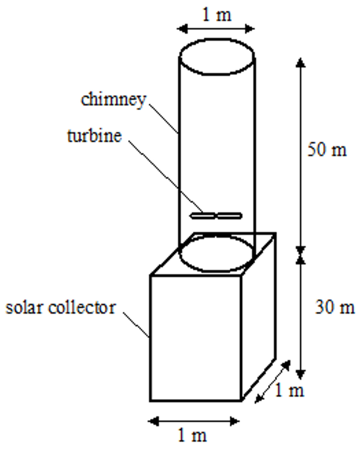
2.1. Solar Chimney and Its Location

The calculations for the solar chimney installation were performed for Katowice. Katowice is a city located in the southern part of Poland. This region is characterized by high industrialization and high population density, which results in a high demand for electricity.

2.2. Solar Chimney

In the article, calculations were made for a solar chimney with a collector positioned at an angle of 90° to the horizontal plane, which consists of a solar collector 30 m long, 1 m wide and with an area of 30 m2 and a chimney 50 m high. The entire installation is 80 m high and faces south.
A wind turbine is located in the chimney. The air is heated in the solar collector and then, as a result of the chimney draft, drives the wind turbine system. The chimney has the same cross-section along its entire height. The side walls of the collector channel are non-transparent and adiabatic. The transport of solar radiation energy takes place only through the surface of the channel roof. The channel and chimney are tightly connected. There is no heat exchange between the air in the chimney and the environment. The roof of the collector is covered with a pane made of glass. Figure 1 shows a diagram of the analyzed solar chimney.

2.3. Mathematical Model

Calculations of Solar Chimney

Air temperature in the collector and air velocity were calculated by the method of successive approximations. The calculations were carried out in accordance with the Formulas (1)–(3) and (9)–(26) used by Pluta in publication [23]. The calculations were made in the following steps.
(1) In the first approximation, the average air temperature in the collector tf and air velocity in the collector cross-section v were assumed, while the collector glass temperature tc was calculated from the formula:
t c = 0.5 ( t f + t a )
(2) The absorber temperature tA is determined from the equation:
t A = t f + 5   ° C
(3) For the assumed temperature tf, the following parameters were read in the tables for dry air at 1013 hPa from [24]: thermal conductivity coefficient λ, Prandtl number Pr, kinematic viscosity coefficient ν and specific heat cp.
(4) In the next step, the convective heat transfer coefficient hc1 is determined:
h c 1 = N u λ d
Nusselt number Nu for an inclined collector for laminar flow (Ra < 109) [25]:
N u = 0.68   +   ( 0.67 R a 1 4 ) / [ 1 + 0.492 P r 9 16 ] 4 9
Nusselt number Nu for an inclined collector for turbulent flow (Ra > 109) [25]:
N u = 0.825 + ( 0.387 R a 1 6 ) / [ 1 + 0.492 P r 9 16 ] 8 27 2
Rayleigh number Ra for turbulent flow [23]:
R a = g β T d 3 ν 2 P r
where β′—air volume expansion coefficient [23]:
β = 2 T A + T c
Rayleigh number Ra for laminar flow [26]:
R a = g c o s θ β T d 3 ν 2 P r
(5) Then, the equivalent heat transfer coefficient from the radiation between the absorber and the glass hr1 is calculated as follows:
h r 1 = σ ( T A 2 + T c 2 ) ( T A + T c ) ( 1 ε A + 1 ε c 1 )
(6) The efficiency of the absorber is determined by the following formula F′:
F = 2 h r 1 h c 1 + U g h c 1 + h c 1 2 U g + h r 1 + h c 1 U d + h r 1 + h c 1 h r 1 2
where Ug—equivalent coefficient of heat loss through the front surface of the collector:
U g = 1 1 h c 2 + h r 2
The convective heat transfer coefficient from the glass surface to the environment caused by the wind hc2 was calculated using the formulas proposed by Pluta [23]:
h c 2 = N u λ L
Nusselt number:
N u = 0.68 R e 1 2 P r 1 3
Reynolds number:
R e = v w · L ν
L = 4 a b a 2 + b 2
hr2—equivalent coefficient of heat transfer by radiation between the glass and the sky:
h r 2 = σ ε c ( T c 4 T s k y 4 ) T c T a
Ud—heat loss coefficient of the collector bottom:
U d = λ i d i
(7) The formula for alternative loss factor UL is as follows:
U L = U d + U g 2 h r 1 h c 1 + h c 1 2 + 2 U g U d h c 1 2 h r 1 h c 1 + h c 1 2 + U g h c 1
(8) The mass flow of air in the first approximation is determined by the following formula:
m ˙ = u 1 A c ρ 0
(9) The air mass flow rate in subsequent approximations is determined using the formula:
m ˙ = V ˙ ρ 0
(10) The next step is to calculate the heat transfer coefficient FR:
F R = m ˙ c p A A U L 1 e x p A A U L F m ˙ c p
(11) The effective capacity of the collector Q is determined from the formula:
Q ˙ = A A F R [ G β τ α U L t i , 1 t a ]
(12) Temperature of the air that leaves the collector channel ti,2:
t i , 2 = t i , 1 + Q ˙ m ˙ c p
(13) The second approximation of the absorber temperature is obtained from the formula:
t A = t a + G β τ α Q ˙ A A U L
(14) The second approximation of the average air temperature is obtained from the equation:
t f = t a + G β τ α Q ˙ F A A U L
The mean transmission–absorption coefficient τα was determined according to the methodology described in [27].
(15) The second approximation of the collector glass temperature is calculated from the formula:
t c = t f h c 1 + t A h r 1 + t a U g h c 1 + h r 1 + U g
(16) Volumetric air flow rate through the chimney:
V ˙ = C d A o 1 + ( A o A i ) 2 2 g H T i , 2     T a T a + 2 g H c o l l T f     T a T a
Average air temperature tf [28]:
t f = γ t o + ( 1   γ ) t i
For the glass temperature, collector absorber, average air temperature in the collector, and air velocity in the collector, the calculations are repeated from the beginning to obtain further approximations.
The electric power of the power plant was determined using the formula based on the assumption that the air force converts a maximum of 2/3 times of the air flow into mechanical power [29]:
P e l = 2 3 P t · η t · u · A c h
Pressure difference generated in the solar chimney [30]:
P t = g ρ 0 ρ i ( H + 1 2 H c o l l )
Air speed u in the chimney channel:
u = V ˙ A c h

3. Results

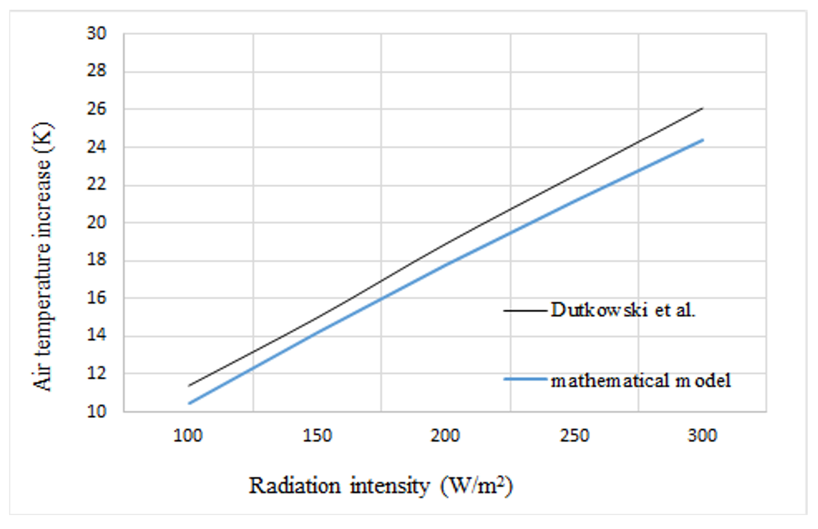
3.1. Model Validation

The model was validated for a vertical air collector for the dependence of the air temperature increase at the collector outlet on the radiation intensity [31].
Figure 2 shows the air temperature increase at the collector outlet depending on the radiation intensity. RMSE is 1.20.
At lower radiation intensities, the difference between the experimentally determined temperature values and the mathematical model is small, whereas at higher radiation intensities this difference increases.

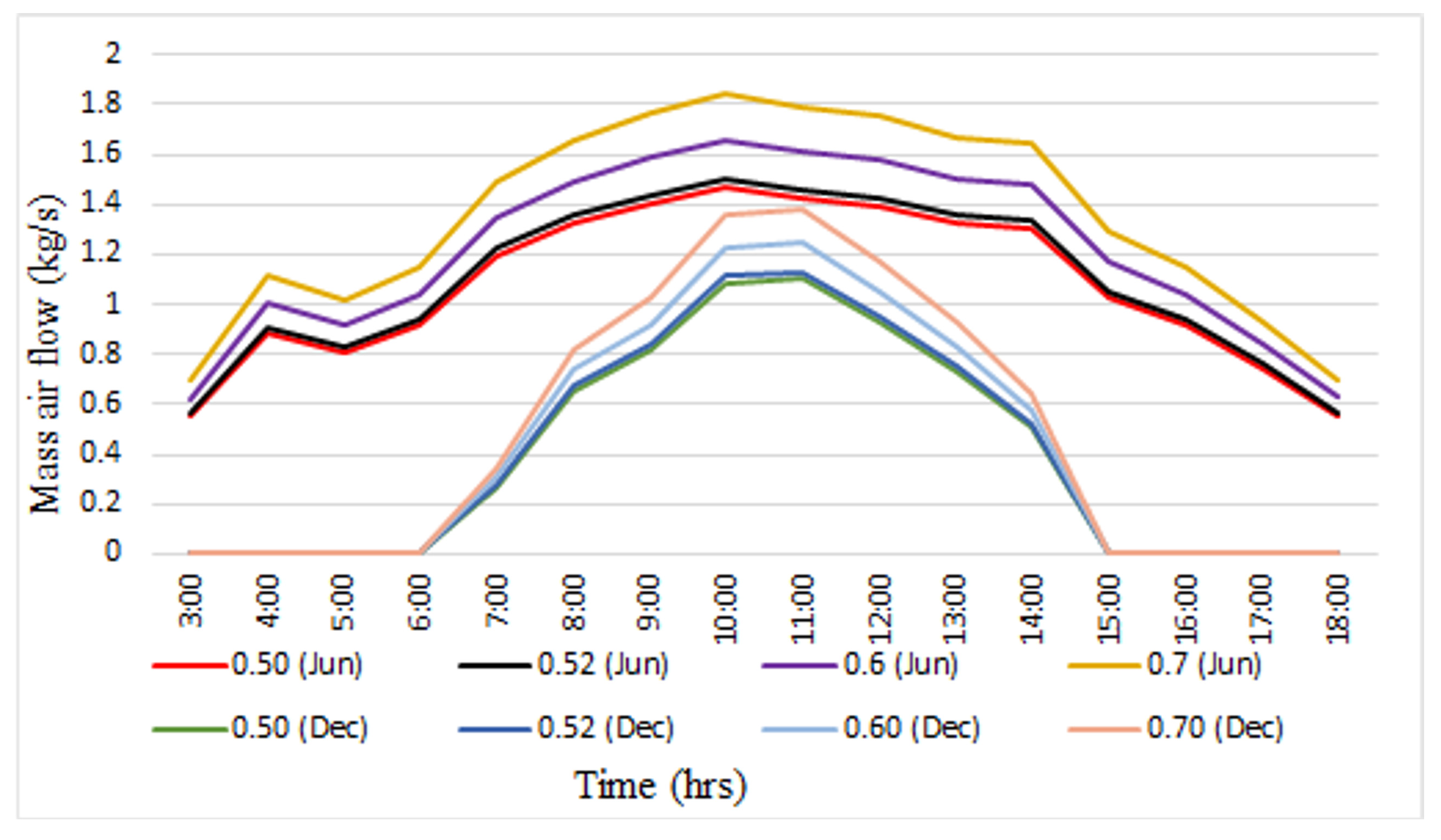
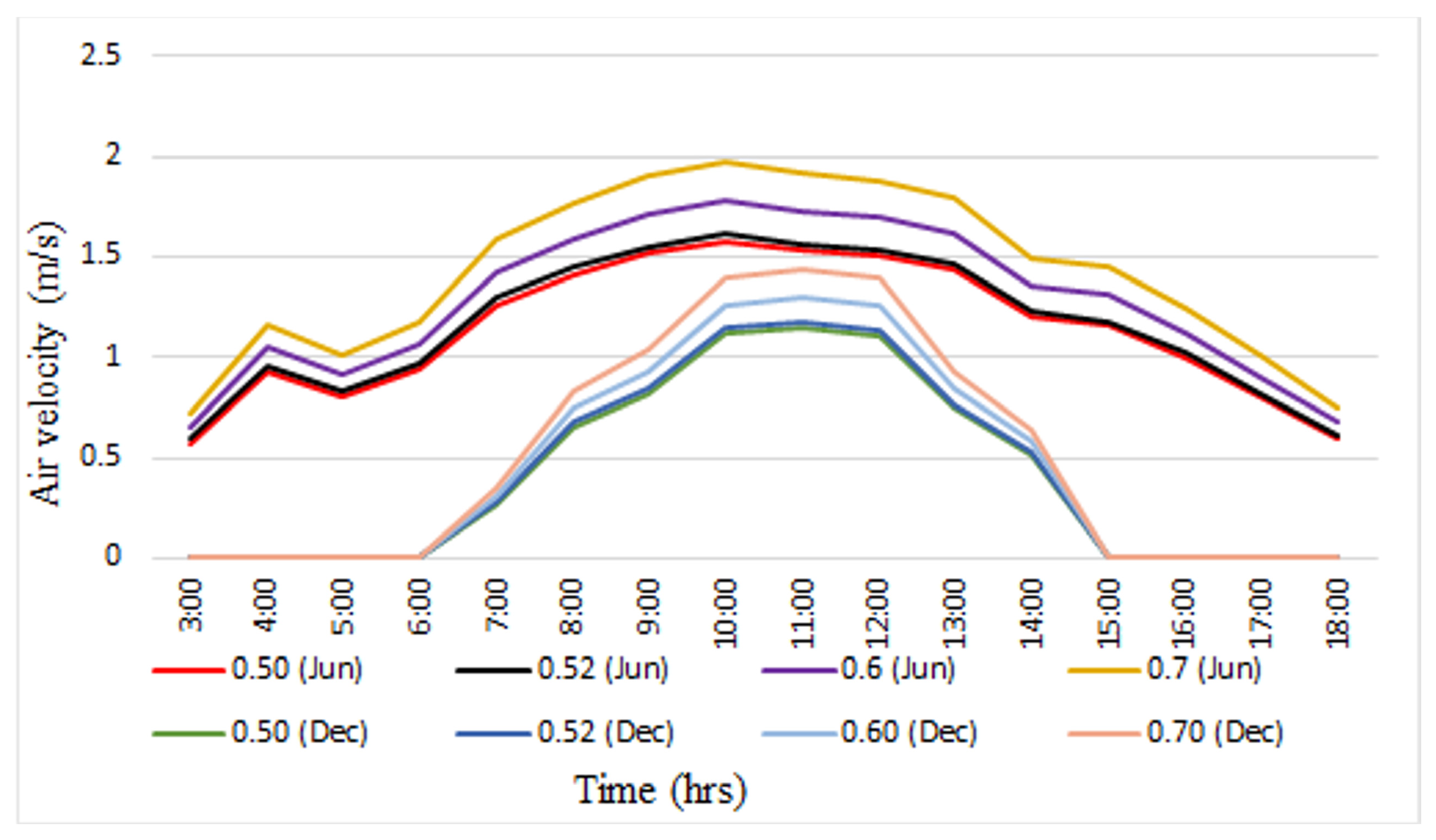
3.2. Sensitivity Analysis for Discharge Coefficient Cd

Discharge coefficient Cd is a parameter used in theoretical mathematical models to determine the mass flow rate of the medium through the installation. In the literature for solar chimneys, the following values can be found: 0.52 defined by Arce et al. [32], 0.57 assumed by Bassioune et al. [33], and 0.6 ± 0.1 assumed by Flourentzou et al. [34].
The graphs present an analysis of the changes in the main operating parameters of the solar chimney (variant A) depending on the assumed discharge coefficient. The analysis is shown for 21 June and 21 December. Discharge coefficient was changed from 0.50 to 0.70.
Figure 3 illustrates the effect of the discharge coefficient on the mass air flow in the solar chimney. As Cd increases, the air flow through the installation increases. The difference in the amount of air flowing is greater, the higher the intensity of solar radiation.
Figure 4 shows the effect of the discharge coefficient on the air velocity in the solar chimney. With the increase in Cd, the air velocity in the installation increases.
Figure 5 shows the effect of the discharge coefficient on the increase in air temperature in the solar chimney. With the increase in Cd, the increase in air temperature in the system decreases.
In this article, the discharge coefficient of 0.52 was assumed for analysis.
This paper presents the analysis of a vertical solar chimney with an absorber covered with a non-selective coating and the currently used three selective coatings. The parameters of the analyzed absorber coatings are shown in Table 1.
The calculations were based on the climatic data for Katowice provided by the Ministry of Investment and Development [36]. The calculations were performed for data for each hour of the day during the calendar year. The analysis was carried out from 1 January to 31 December for 8760 h during the year. The following quantities were used in the calculations: total solar radiation on a plane situated at an angle of 90°, direct solar radiation on a horizontal plane, diffuse solar radiation on a horizontal plane, dry bulb temperature, air velocity, and sky temperature. Table 2 presents the main assumptions for the calculations.
Types of the analyzed installations:
(1)
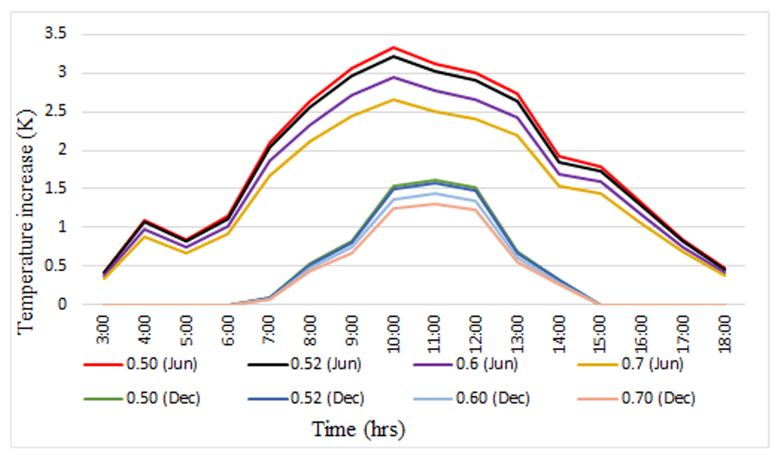
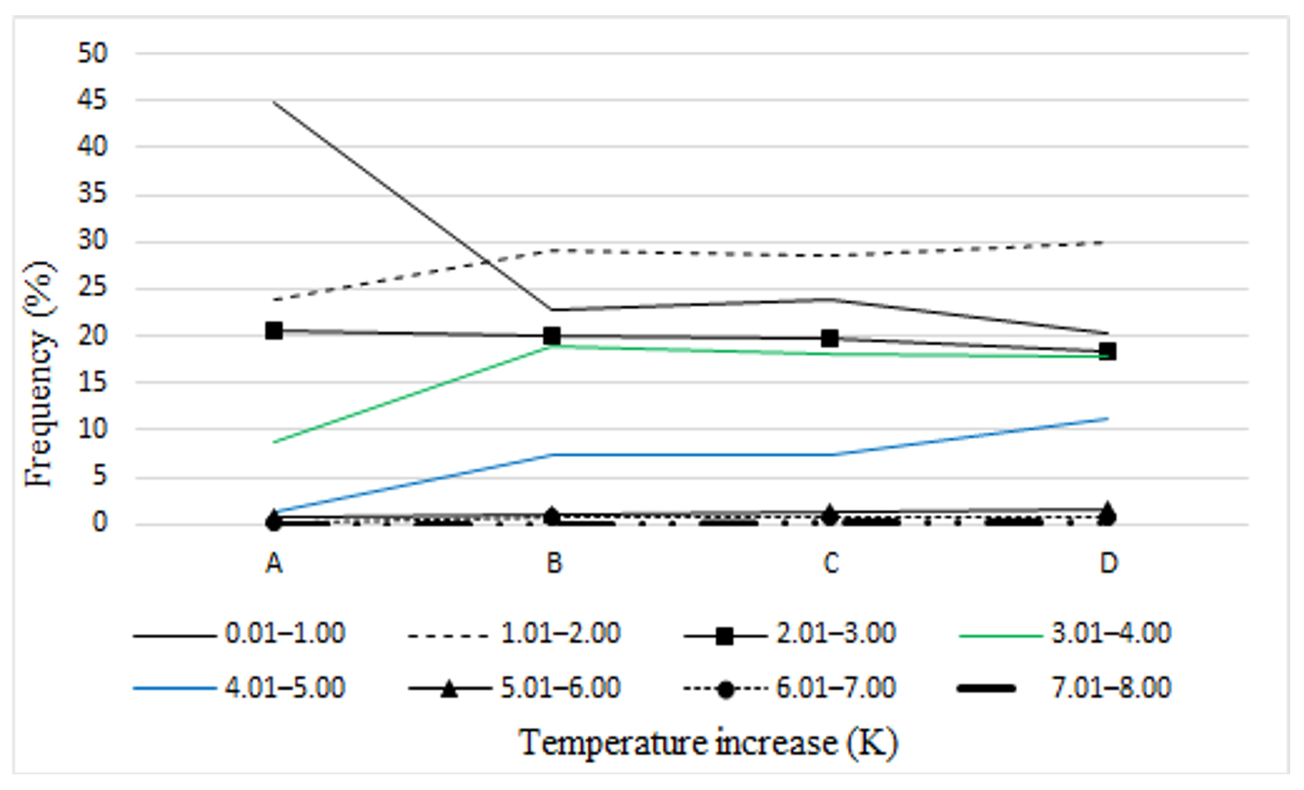
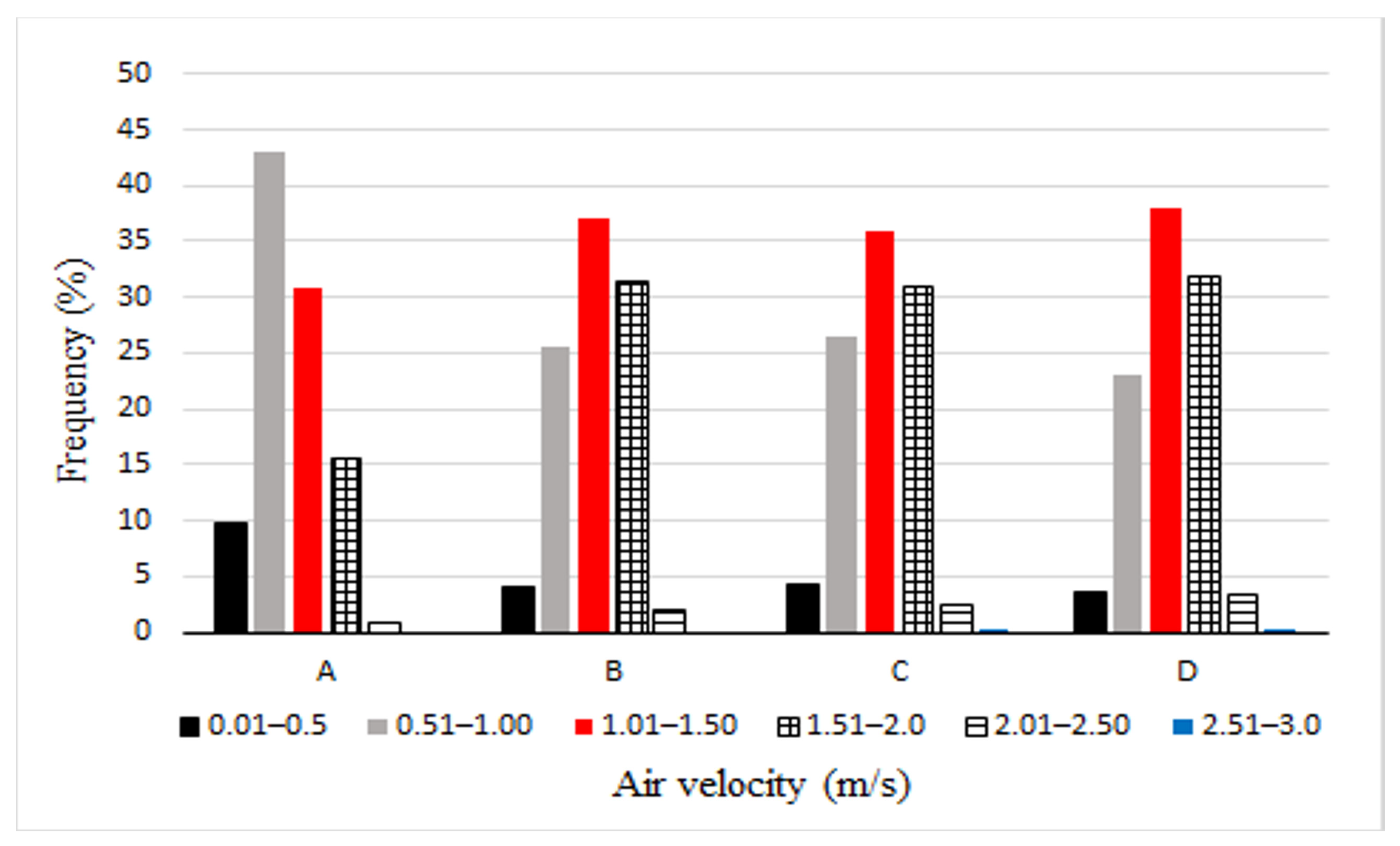
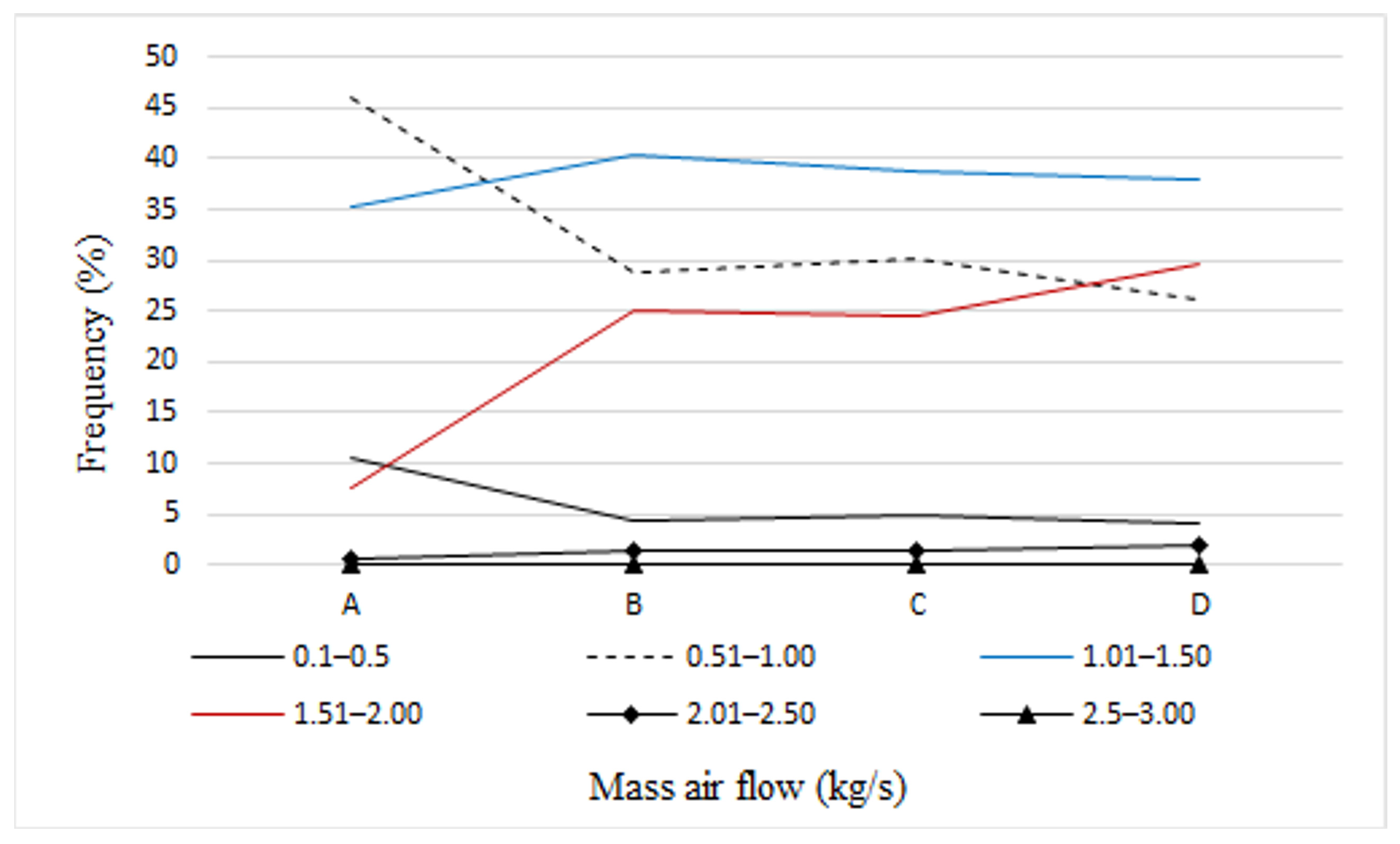
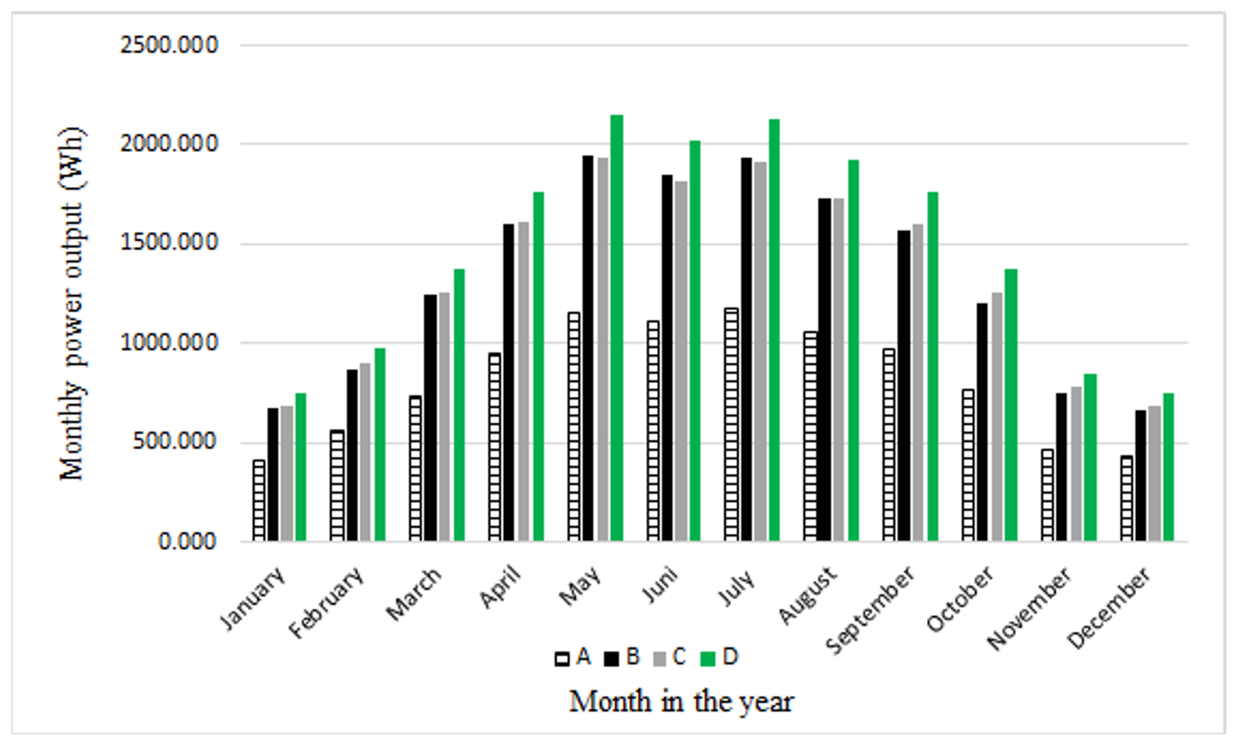
Variant A is an installation with an absorber covered with black paint with an absorption coefficient of 0.95 and an emission coefficient of 0.95.
(2)
Variant B is a system with an absorber covered with CuO with an absorption coefficient of 0.85 and an emission coefficient of 0.11.
(3)
Variant C is a system with an absorber covered with black chrome with an absorption coefficient of 0.98 and an emission coefficient of 0.14.
(4)
Variant D is a system with an absorber covered with TiNOX with an absorption coefficient of 0.95 and an emission coefficient of 0.05.
Figure 6 shows the frequency of air temperature increase (ΔT) at the collector outlet during a calendar year for the analyzed cases of solar chimney installation.
The highest temperature increase of 7.01–8.00 K occurred in installations C and D. The temperature increase of 6.01–7.00 K occurred in all analyzed installations. The temperature increase of 0.01–2.00 K occurred with the highest frequency in all installations. ΔT from 3.01 to 4.00 K in variant B occurred with a frequency of 19.02% and in system A with a frequency of 8.73%. The temperature increase in the range of 4.01–5.00 K occurred with a frequency of 11.17% in installation D and in system A with a frequency of 1.21%.
Figure 7 shows the frequency of occurrence of air velocity ranges in the solar chimney during a calendar year for the tested installations.
In system A, the highest air speed in the range of 2.01–2.50 m/s occurred with the lowest frequency. An air speed of 0.51–1.00 m/s occurred with the highest frequency of 43.06%. The lowest air speed of 0.01–0.5 m/s occurred with a frequency of 9.79%. In variant B, the highest air speed of 2.01–2.50 m/s occurred with a frequency of 2.05%, while the lowest 0.01–0.5 m/s occurred with a frequency of 4.04%. The highest frequency of 37.02% was for the air speed of 1.01–1.5 m/s. An air speed in the range of 1.51–2.00 m/s occurred with a frequency of 31.41%.
In installation C, the highest air velocity of 2.51–3.00 m/s occurred with a frequency of 0.07%. The lowest air velocity of 0.01–0.5 m/s had a frequency of 4.26%. The highest frequency was in the range of 1.01–2.00 m/s.
In system D, the highest air velocity of 2.51–3.00 m/s occurred with a frequency of 0.14%. The lowest air velocity of 0.01–0.5 m/s had a frequency of 3.51%. The highest frequency was in the range of 1.01–1.50 m/s. The air velocity of 2.01–2.50 m/s occurred with a frequency of 3.28%.
Figure 8 shows the frequency of occurrence of mass air flow ranges in the solar chimney during a calendar year for the analyzed installations.
In the analyzed installations, the lowest frequency was for the mass air flow of 2.01–3.00 kg/s. In variant A, the highest frequency was for the mass air flow of 0.51–1.00 kg/s. In systems B, C and D, the highest frequency can be observed for 1.01–1.50 kg/s.
The lowest range of the mass air flow of 0.1–0.5 kg/s occurred with the highest frequency of 10.47% in system A, while in the remaining installations the frequency was 3.97–4.97%.
The mass air flow in the range of 1.51–2.00 kg/s in variant A occurred with a frequency of 7.51%, while in variants B, C and D the frequency ranged from 24.41% to 29.6%.
Figure 9 shows the amount of energy produced in each month for the analyzed solar chimney systems. The largest amount of electricity is produced in spring and summer, while the smallest is produced in autumn and winter. The highest electricity generation occurs in May and June, while the lowest occurs in December and January.
Table 3 shows the total amount of electricity generated during the year. Of the analyzed solar chimney systems, installation D allows for the generation of the largest amount of electricity, while installation A produces the smallest amount. Installations B and C produce similar amounts of electricity. Installation C produces more electricity than variant B from September to April and generates a smaller amount from May to August. Over the entire year, installation C produces more electricity than installation B.
Figure 10 presents a percentage comparison of electricity generation in individual months for the analyzed installations compared to variant A.
The largest difference in the amount of generated electricity between case A and the other installations occurs in March. Installation B allows for the production of 70.4% more energy, installation C 71.9%, and installation D 88.2% more electricity. The smallest difference in the amount of generated electricity occurs in December. Installation B allows for the production of 52.3% more energy, system C 58.1%, and installation D 71.7% more electricity.
Table 4 lists the costs of individual coatings and the cost of electricity generation.
The cost of electricity generation was calculated from the following relationship:
E l e c t r i c i t y   g e n e r a t i o n   c o s t = c o a t i n g   c o s t · a b s o r b e r   a r e a a m o u n t   o f   e l e c t r i c i t y   g e n e r a t e d   d u r i n g   a   y e a r  
The highest material costs were incurred for aluminum-coated CuO, the lowest for black paint. The cost of generating electricity is the highest for aluminum-coated CuO, and the lowest for black chrome.

4. Discussion

Vertical collectors and solar chimneys are being researched all over the world in buildings for ventilation purposes [32,41,42,43,44,45].
This paper presents an analysis of a vertical solar chimney with a non-selective and selective absorbers. The solar chimney faced south. In Katowice, the most favorable conditions for solar radiation are in this geographical direction. Due to the variable intensity of radiation and cloudiness, a year-round analysis of the solar chimney was carried out.
Calculations of the operating parameters of the solar chimney installation: air temperature increase, air velocity and mass air flow were reflected in the generation of electricity. In system A, it was observed that the lower ranges of these parameters occur with greater frequency than in the other installations, and in this system the least electricity can be obtained. In variants B, C and D, the higher ranges of the tested parameters had a greater frequency, which, as a result, translates into a greater amount of generated electricity. In installation B, the absorber coverage was characterized by a lower emission coefficient and a lower absorption coefficient than the absorber coverage in installation C. Variants B and C generated similar amounts of electricity. The year-round analysis of the operation of these installations allowed the amounts of generated electricity in the individual months of the year to be shown. Installation B produced more electricity than variant C in the spring and summer months but less in the autumn and winter periods.
Periodic changes in the angle of incidence of the sun’s rays, the length of the day, cloudiness, humidity and air turbidity determine the amount of solar energy reaching the collector.
The differences in the amount of electrical energy generated by the analyzed absorbers are greater at lower latitudes (characterized by high solar radiation and a dry climate), compared to areas located at higher latitudes (characterized by lower solar radiation and a humid climate).

5. Conclusions

The article presents the main parameters of solar chimney operation: air temperature at the collector outlet, air velocity in the solar chimney and mass air flow. The frequencies of occurrence of these parameters during a calendar year in installations with a solar collector with an absorber characterized by different absorption and emission coefficients of solar radiation were compared. The amount of electricity generated during the year was also shown. The most important conclusions of the analysis are:
(1)
The largest increases in temperature, air velocity and mass air flow can be achieved in systems with an absorber characterized by the highest absorption coefficient and the lowest emission coefficient.
(2)
The installation of a solar chimney with an absorber covered with a selective coating having an absorption coefficient of 0.95 and an emission coefficient of 0.05 allowed the generation of the largest amount of electricity during the year.
(3)
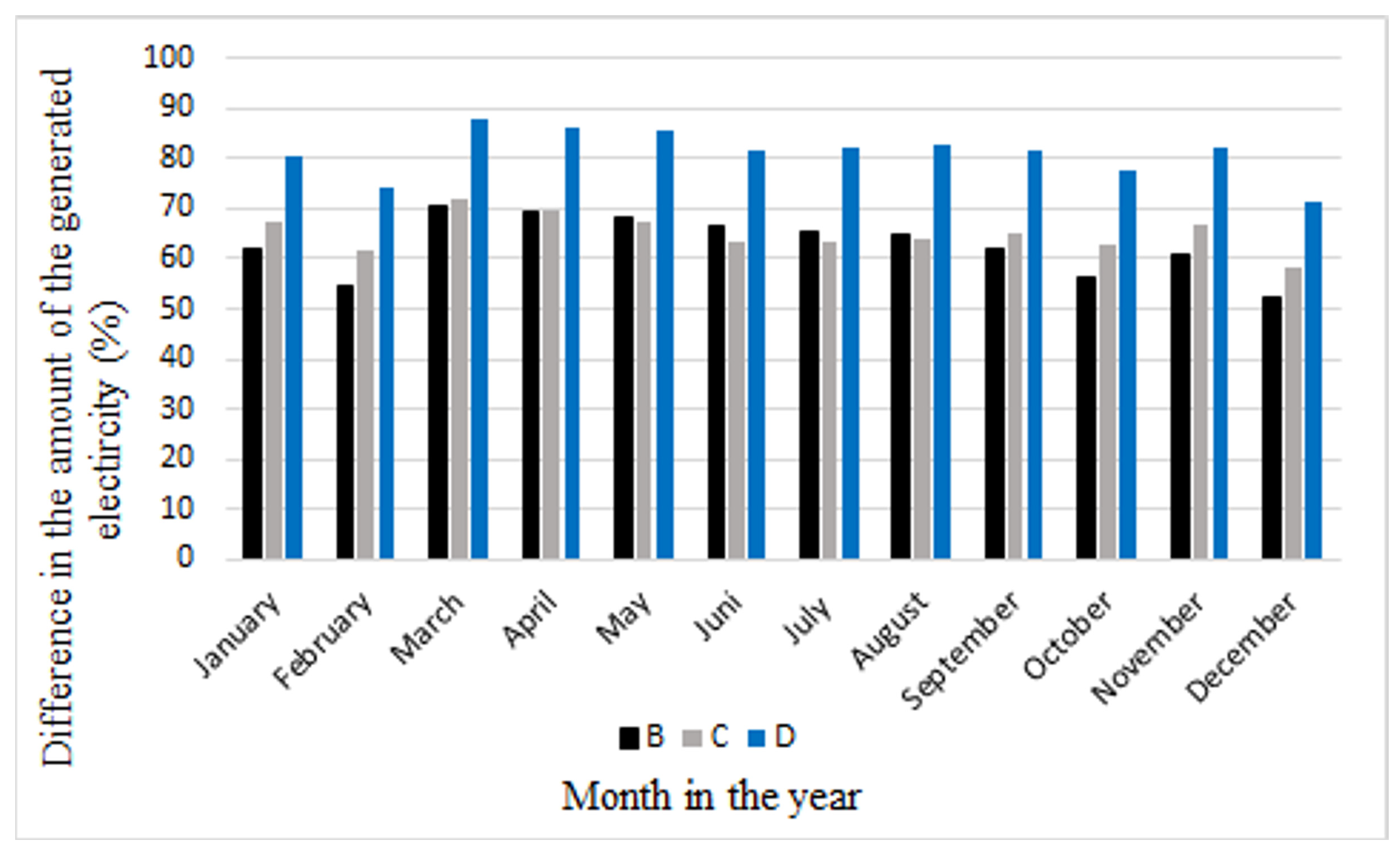
The year-long analysis of the solar chimney operation showed that the use of selective absorber coatings allows for the generation of an average of 62.8% (variant B) to 81.4% (variant D) more electricity compared to an absorber with a non-selective coating.

Funding

This research received no external funding.

Data Availability Statement

Data for Energy Calculations of Buildings available online: https://www.gov.pl/web/archiwum-inwestycje-rozwoj/dane-do-obliczen-energetycznych-budynkow (accessed on 8 January 2022). Sandtex 10 year black satin multi-surface paint 2.5 l available online: https://www.diy.com/departments/sandtex-10-year-black-satin-multi-surface-paint-2-5l/5010131585135_BQ.prd (accessed on 8 July 2025). Black Anodizing Services available online: https://www.indiamart.com/proddetail/black-anodizing-services-2851205644930.html (accessed on 8 July 2025). Absorber TiNOX Blue Selective coating for Flat Plate Collector available online: https://smmtmaterial.en.made-in-china.com/product/vaoRWiDVYGcr/China-Absorber-Tinox-Blue-Selective-Coating-for-Flat-Plate-Solar-Collector.html (accessed on 8 July 2025).

Conflicts of Interest

The author declares no conflict of interest.

Nomenclature

AAabsorber surface, m2
Accollector cross-section, m2
Achcross-section of the chimney, m2
Aicross-sectional area of the inlet, m2
Aocross-sectional area of the outlet, m2
alength of the collector side, m
blength of the collector side, m
Cdcoefficient of discharge
cpspecific heat, J/kgK
ddistance between glass and absorber, m
diinsulation thickness of the collector bottom, m
F′efficiency of the absorber
FRheat transfer coefficient
G β total radiation on an inclined surface, W/m2
ggravitational acceleration, m/s2
Hheight of the chimney, m
Hcollheight of the collector, m
hc1convective heat transfer coefficient, W/m2K
hr1heat transfer coefficient from the radiation between the absorber and the glass, W/m2K
hr2equivalent coefficient of heat transfer by radiation between the glass and the sky, W/m2K
hc2convective heat transfer coefficient from the glass surface to the environment caused by the wind, W/m2K
Lcharacteristic value
m ˙   air mass flow, kg/s
NuNusselt number
Pelelectric power, W
PrPrandtl number
Qeffective capacity of the collector, W
RaRayleigh number
ReReynolds number
Taambient temperature, K
TAabsorber temperature, K
Tcglass temperature, K
Tfaverage air temperature in the collector, K
Tskytemperature of the sky, K
tAabsorber temperature, °C
taambient temperature, °C
tcglass temperature, °C
tfaverage air temperature in the collector, °C
titemperature of the air that leaves the collector channel, °C
ti,2temperature at the inlet of the chimney, °C
uair speed in the chimney channel, m/s
u1air speed assumed in first approximation, m/s
Udheat loss coefficient of the collector bottom, W/m2K
ULloss factor, W/m2K
Ugequivalent coefficient of heat loss through the front surface of the collector, W/m2K
V ˙ volumetric air flow rate through the chimney, m3/s
vwwind speed, m/s
Greek symbols
β′air volume expansion coefficient, 1/K
γconstant, equal 0.75
εAabsorber emissivity
εcglass emissivity
ηtefficiency of the turbine
θangle between vertical plane and collector, °
λthermal conductivity coefficient, W/mK
λithermal conductivity coefficient of the collector’s thermal insulation, W/mK
νkinematic viscosity coefficient, m2/s
ρiair density at the inlet to the chimney, kg/m3
ρ0air density at the inlet to the collector, kg/m3
σStefan–Boltzmann constant, W/m2K4
ταmean transmission–absorption coefficient
P t   pressure difference generated in the solar chimney, Pa
ΔTtemperature difference between absorber and glass, K

References

  1. Xaman, J.; Vargas-Lopez, R.; Gijon-Rivera, M.; Zavala-Guillen, I.; Jimenez, M.J.; Arce, J. Transient thermal analysis of a solar chimney for buildings with three different types of absorbing materials: Copper plate/PCM/concrete wall. Renew. Energy 2019, 136, 139–158. [Google Scholar] [CrossRef]
  2. Hirunlabh, J.; Kongduang, W.; Namprakai, P.; Khedari, J. Study of natural ventilation of houses by a metallic solar wall under tropical climate. Renew. Energy 1999, 18, 109–119. [Google Scholar] [CrossRef]
  3. Naraghi, M.H.; Blanchard, S. Twenty-four hour simulation of solar chimneys. Energy Build. 2015, 94, 219–226. [Google Scholar] [CrossRef]
  4. El-Sebaii, A.A.; Al-Snani, H. Effect of selective coating on the thermal performance of flat plate solar air heaters. Energy 2010, 35, 1820–1828. [Google Scholar] [CrossRef]
  5. Smolec, W.; Jaroszyński, M.; Janus, B. Wpływ właściwości absorbera i szyb na sprawność płaskich kolektorów słonecznych do podgrzewania powietrza. Pr. Nauk. IICh PAN 2010, 14, 21–39. [Google Scholar]
  6. Huh, J.; Ahn, C.S.; Rahaman, M.; Bang, B.H.; Yarin, A.L.; Aldalbahi, A.; Yoon, S.S. Enhancing the buoyancy of air flows inside vertical solar chimneys using a G/CNT/AgNW-coated heat collector. Int. Commun. Heat Mass Transf. 2024, 156, 107675. [Google Scholar] [CrossRef]
  7. Al-Rjoub, A.; Rebouta, L.; Costa, P.; Vieira, L. Multi-layer solar selective absorber coatings based on W/WSiAlNx/WSiAlOyNx/SiAlOx for high temperature applications. Sol. Energy Mater. Sol. Cells 2018, 186, 300–308. [Google Scholar] [CrossRef]
  8. Dan, A.; Biswas, A.; Sarkar, P.; Kashyap, S.; Chattopadhyay, K.; Barshilia, H.C.; Basu, B. Enhancing spectrally selective response of W/WAlN/WAlON/Al2O3–based nanostructured multilayer absorber coating through graded optical constants. Sol. Energy Mater. Sol. Cells 2018, 176, 157–166. [Google Scholar] [CrossRef]
  9. Salarpour, N.; Azadani, L.N. Optimization and evaluation of thermo-hydraulic performance of solar air heaters equipped with different roughness geometries. Case Stud. Therm. Eng. 2024, 61, 105037. [Google Scholar] [CrossRef]
  10. Atia, A.; Bouabdallah, S.; Ghernaout, B.; Teggar, M.; Benchatti, T. Applied, Investigation of various absorber surface shapes for performance improvement of solar chimney power plant. Therm. Eng. 2023, 235, 121395. [Google Scholar] [CrossRef]
  11. Sheelam, S.; Chandramohan, V.P. Influence of pitch and height of pentagonal ribbed absorber plate of solar air heater for performance enhancement with environmental analysis. Therm. Sci. Eng. Prog. 2024, 56, 103035. [Google Scholar] [CrossRef]
  12. Abulkhair, H.; Alsaiari, A.O.; Ahmed, I.; Almatrafi, E.; Madhukeshwara, N.; Sreenivasa, B. Heat transfer and air flow friction in solar air heaters: A comprehensive computational and experimental investigation with wire-roughened absorber plate. Case Stud. Therm. Eng. 2023, 48, 103148. [Google Scholar] [CrossRef]
  13. Kamali, R.; Binesh, A.R. The importance of rib shape effects on the local heat transfer and flow friction characteristics of square ducts with ribbed internal surfaces. Int. Commun. Heat Mass Transf. 2008, 35, 1032–1040. [Google Scholar] [CrossRef]
  14. Karmveer, T.A.; Gupta, N.K.; Singh, H. An experimental study of thermohydraulic performance of solar air heater having multiple open trapezoidal rib roughnesses. Exp. Heat Transf. 2024, 37, 313–333. [Google Scholar] [CrossRef]
  15. Chaudhari, M.; Sharma, S.L.; Debbarma, A. Exergetic performance analysis of solar air heater with inverted L-shape ribs as roughness element. Arch. Thermodyn. 2023, 44, 241–267. [Google Scholar] [CrossRef]
  16. Ghritlahre, H.K. An experimental study of solar air heater using arc shaped wire rib roughness based on energy and exergy analysis. Arch. Thermodyn. 2021, 42, 115–139. [Google Scholar] [CrossRef]
  17. Lei, Y.; Zhang, Y.; Wang, F.; Wang, X. Enhancement of natural ventilation of a novel roof solar chimney with perforated absorber plate for building energy conservation. Appl. Therm. Eng. 2016, 107, 653–661. [Google Scholar] [CrossRef]
  18. Itaya, Y.; Adachi, K.; Mizuno, M.; Hasatani, M. Heat transfer and heat storage characteristics of optically semitransparent-material packed-bed solar air heater. J. Chem. Eng. Jpn. 1989, 22, 11–17. [Google Scholar] [CrossRef]
  19. Chen, W.; Qu, M. Analysis of the heat transfer and airflow in solar chimney drying system with porous absorber. Renew. Energy 2014, 63, 511–518. [Google Scholar] [CrossRef]
  20. Din, S.I.U.; Ibrahim, A.; Ajeel, R.K.; Fazlizan, A.; Ishak, A.A.; Al-Aasam, A.B. Thermal performance analysis of a double-pass solar air heater with lava rock as porous and sensible heat storage material. J. Energy Storage 2024, 95, 112564. [Google Scholar] [CrossRef]
  21. Shbailat, S.J.; Nima, M.A. Possible energy saving of evaporative passive cooling using a solar chimney of metal foam porous absorber. Energy Convers. Manag. 2021, 12, 100118. [Google Scholar] [CrossRef]
  22. Pretorius, J.P.; Kroger, D.G. Critical evaluation of solar chimney power plant performance. Sol. Energy 2006, 80, 535–544. [Google Scholar] [CrossRef]
  23. Pluta, Z. Podstawy Teoretyczne Fototermicznej Konwersji Energii Słonecznej; Politechniki Warszawskiej: Warszawa, Poland, 2006. [Google Scholar]
  24. Pudlik, W. Wymiana i Wymienniki Ciepła; Politechnika Gdańska: Gdańsk, Poland, 2012. [Google Scholar]
  25. Incopera, F.P.; DeWitt, D.P. Fundamentals of Heat and Mass Transfer; John Wiley: Hoboken, NJ, USA, 1996. [Google Scholar]
  26. Bejan, A. Convection Heat Transfer; John Wiley & Sons: Hoboken, NJ, USA, 2013. [Google Scholar]
  27. Berdowska, S. Analysis of the all-year operation of the solar chimney in Polish climatic conditions. Energies 2022, 15, 4738. [Google Scholar] [CrossRef]
  28. Ong, K.S. A mathematical model of a solar chimney. Renew. Energy 2003, 28, 1047–1060. [Google Scholar] [CrossRef]
  29. Schlaich, J. The Solar Chimney-Electricity from the Sun; Edition Axel Menges: Stuttgart, Germany, 1995. [Google Scholar]
  30. Cao, F.; Zhao, L.; Li, H.; Guo, L. Performance analysis of conventional and sloped solar chimney power plants in China. Appl. Therm. Eng. 2013, 50, 582–592. [Google Scholar] [CrossRef]
  31. Dutkowski, K.; Piątkowski, P. Badania eksperymentalne prototypowego, pasywnego powietrznego kolektora słonecznego z pokryciem poliwęglanem komorowym. Instal 2015, 3, 17–23. [Google Scholar]
  32. Arce, J.; Jiménez, M.J.; Guzmán, J.D.; Heras, M.R.; Alvarez, G.; Xamán, J. Experimental study for natural ventilation on a solar chimney. Renew. Energy 2009, 34, 2928–2934. [Google Scholar] [CrossRef]
  33. Bassiouny, R.; Koura, N.S.A. An analytical and numerical study of solar chimney use for room natural ventilation. Energy Build. 2008, 40, 865–873. [Google Scholar] [CrossRef]
  34. Flourentzou, F.; Van der Maas, J.; Roulet, C.A. Natural ventilation for passive cooling: Measurement of discharge coefficients. Energy Build. 1998, 27, 283–292. [Google Scholar] [CrossRef]
  35. Wiśniewski, G.; Gołębiowski, S.; Gryciuk, M.; Kurowski, K.; Więcka, A. Kolektory Słoneczne, Energia Słoneczna w Mieszkalnictwie, Hotelarstwie i Drobnym Przemyśle; Dom wydawniczy MEDIUM: Warszawa, Poland, 2008. [Google Scholar]
  36. Ministerstwo Inwestycji i Rozwoju Rzeczypospolitej Polskiej. Data for Energy Calculations of Buildings. Available online: https://www.gov.pl/web/archiwum-inwestycje-rozwoj/dane-do-obliczen-energetycznych-budynkow (accessed on 8 January 2022).
  37. B&Q, United Kingdom. Sandtex 10 Year Black Satin Multi-Surface Paint 2.5 l. Available online: https://www.diy.com/departments/sandtex-10-year-black-satin-multi-surface-paint-2-5l/5010131585135_BQ.prd (accessed on 8 July 2025).
  38. IndiaMART. Black Anodizing Services. Available online: https://www.indiamart.com/proddetail/black-anodizing-services-2851205644930.html (accessed on 8 July 2025).
  39. Kwon, Y.S.; Li, Y.; Huang, B. Scalable, Low-Cost Fabrication of Selective Solar Absorber by Ultrasonic Spray Coating. ES Mater. Manuf. 2023, 20, 812. [Google Scholar] [CrossRef]
  40. Made-in-China B2B Sales Platform. Absorber Tinox Blue Selective coating for Flat Plate Collector. Available online: https://smmtmaterial.en.made-in-china.com/product/vaoRWiDVYGcr/China-Absorber-Tinox-Blue-Selective-Coating-for-Flat-Plate-Solar-Collector.html (accessed on 8 July 2025).
  41. Ren, X.H.; Wang, P.L.; Zhang, C.X.; Song, Y.J.; Shang, J.; Wang, L.; Zhao, F.Y. Heat removal and ventilation limitations of the solar chimney attached with a built enclosure: Correlations of thermal Rayleigh numbers, port arrangements and discrete heating elements. Renew. Energy 2024, 221, 119782. [Google Scholar] [CrossRef]
  42. Zhang, H.; Tao, Y.; Nguyen, K.; Han, F.; Li, J.; Shi, L. A wall solar chimney to ventilate multi-zone buildings. Sustain. Energy Technol. Assess 2021, 47, 101381. [Google Scholar] [CrossRef]
  43. Wang, H.; Lei, C. A numerical investigation of combined solar chimney and water wall for building ventilation and thermal comfort. Build. Environ. 2020, 171, 106616. [Google Scholar] [CrossRef]
  44. Asadi, S.; Fakhari, M.; Fayaz, R.; Mahdaviparsa, A. The effect of solar chimney layout on ventilation rate in buildings. Energy Build. 2016, 123, 71–78. [Google Scholar] [CrossRef]
  45. Saifi, N.; Baadi, A.; Ghedamsi, R.; Guerrout, A.; Settou, N. An experimental study and numerical simulation of natural ventilation in a semi-arid climate building using a wind catcher with evaporative cooling system and solar chimney. J. Build. Eng. 2024, 85, 108475. [Google Scholar] [CrossRef]
Figure 1. Solar chimney.
Energies 18 03740 g001
Figure 2. Air temperature increase at the collector outlet. The blue line represents the mathematical model, the black line represents the results from Dutkowski et al. [31].
Energies 18 03740 g002
Figure 3. Effect of Cd on mass air flow in solar chimney.
Energies 18 03740 g003
Figure 4. Effect of Cd on air velocity.
Energies 18 03740 g004
Figure 5. Effect of Cd on temperature increase.
Energies 18 03740 g005
Figure 6. Frequency of temperature increase during the year in the analyzed solar chimney installations.
Energies 18 03740 g006
Figure 7. Frequency of air velocity occurrences during the year in the analyzed solar chimney installations.
Energies 18 03740 g007
Figure 8. Frequency of mass air flow during the year in the analyzed solar chimney installations.
Energies 18 03740 g008
Figure 9. Amount of electricity produced by the solar chimney.
Energies 18 03740 g009
Figure 10. Comparison of the electricity produced in each installation with variant A.
Energies 18 03740 g010
Table 1. Parameters of the analyzed absorber coatings [35].
Collector CoverAbsorption Coefficient, αEmission Coefficient, ε
Black paint0.950.95
Aluminum-coated CuO0.850.11
Black chrome0.980.14
TiNOX0.950.05
Table 2. The main assumptions for the calculations.
ParameterValue
Gravitational acceleration9.81 m/s2
Stefan–Boltzmann constant5.67∙10−8
Ground reflectivity0.2
Coefficient of reflection of radiation from the interface0.142
Extinction coefficient20 m−1
Collector glass thickness0.004 m
Glass emissivity0.95
Absorber area30 m2
Chimney height50 m
Diameter of the chimney1 m
Turbine efficiency0.8
Table 3. The amount of electricity generated during a year.
InstallationAmount of Electricity
A9773.7 Wh
B16,031.2 Wh
C16,155.0 Wh
D17,806.6 Wh
Table 4. Costs of coating and electricity generation.
Collector CoverCoating Cost ($/m2)Electricity Generation Cost ($/Wh)
Black paint6.0 [37]0.018
Aluminum-coated CuO16.2 [38]0.030
Black chrome8.0 [39]0.015
TiNOX10.0 [40]0.017
Disclaimer/Publisher’s Note: The statements, opinions and data contained in all publications are solely those of the individual author(s) and contributor(s) and not of MDPI and/or the editor(s). MDPI and/or the editor(s) disclaim responsibility for any injury to people or property resulting from any ideas, methods, instructions or products referred to in the content.

