
Non-Magnetic Assembly Technology and Mechanical Performance Analysis of Permanent Magnet Integrated Motor for Ball Mills


Abstract
1. Introduction
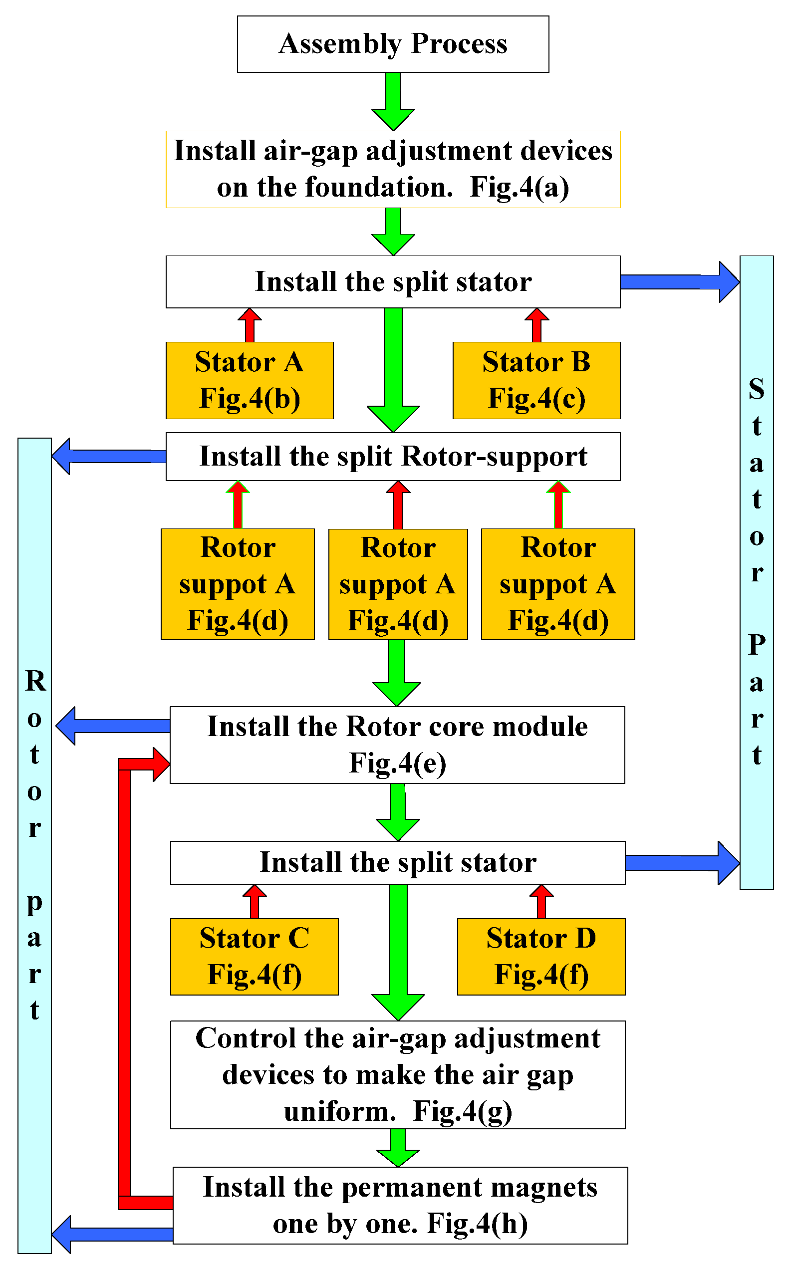
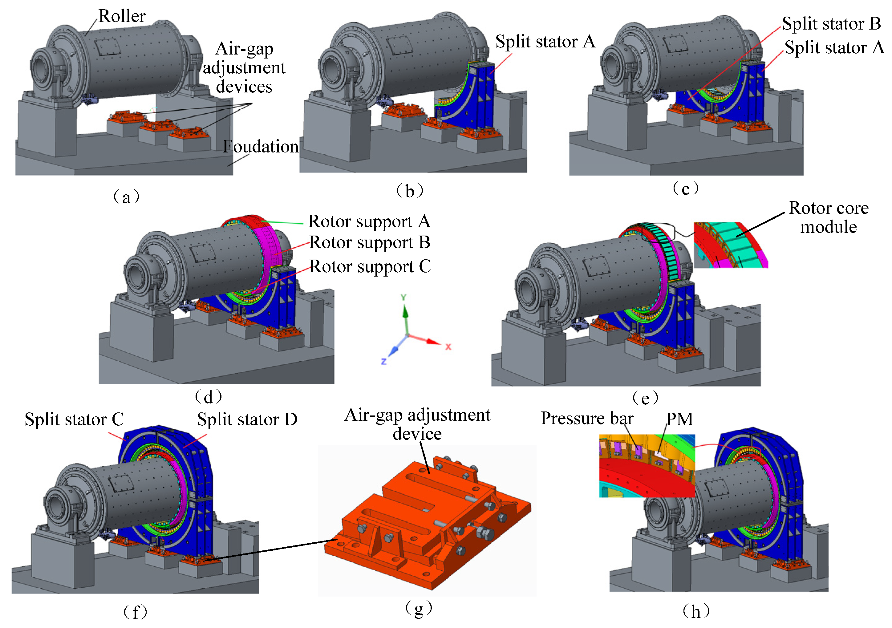
2. Structure and Non-Magnetic Assembly Technology of PMIM for Ball Mills
- (1)
- Install air gap adjustment device
- (2)
- Assembly of split stators A and B
- (3)
- Assembly of rotor support and rotor core
- (4)
- Complete stator and air gap adjustment
- (5)
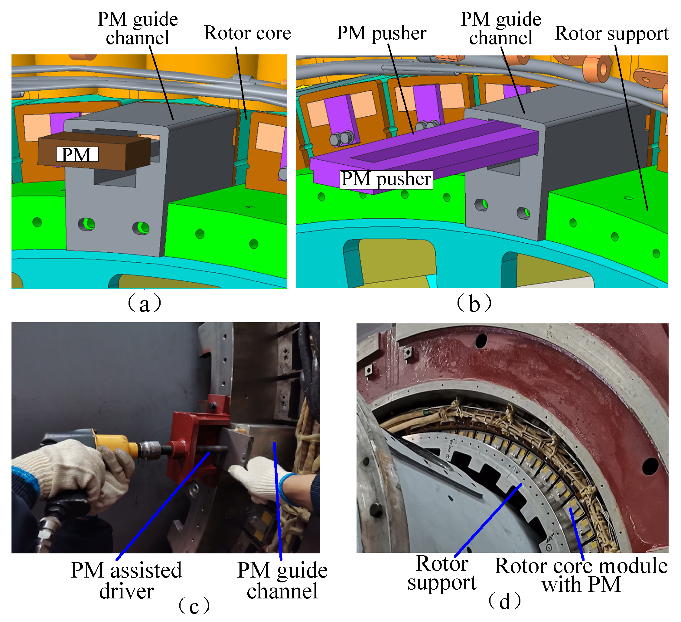
- Assembly of PM
3. Analytical Modeling of Magnetic and Non-Magnetic Assembled Stator Loads
4. Mechanical Performance Analysis of Magnetic and Non-Magnetic Assembly
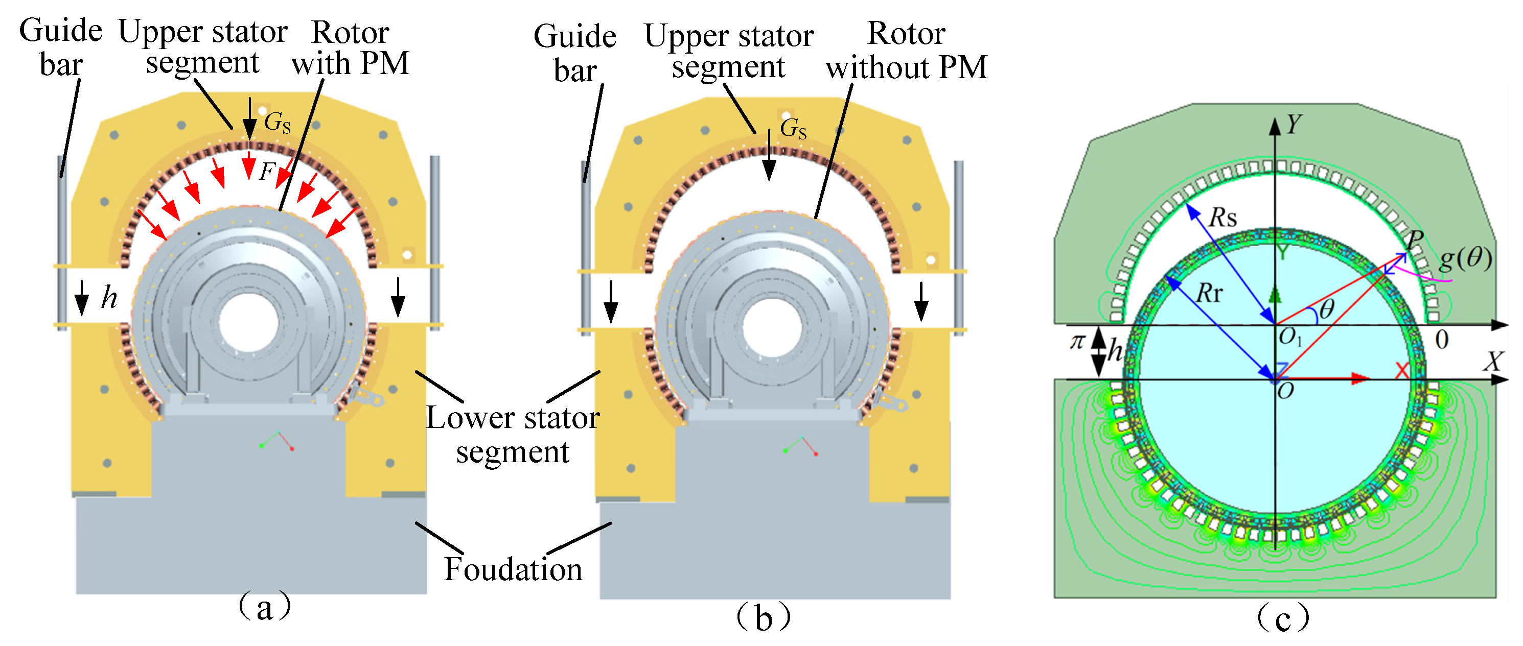
4.1. Mechanical Analysis of Stator During Assembly
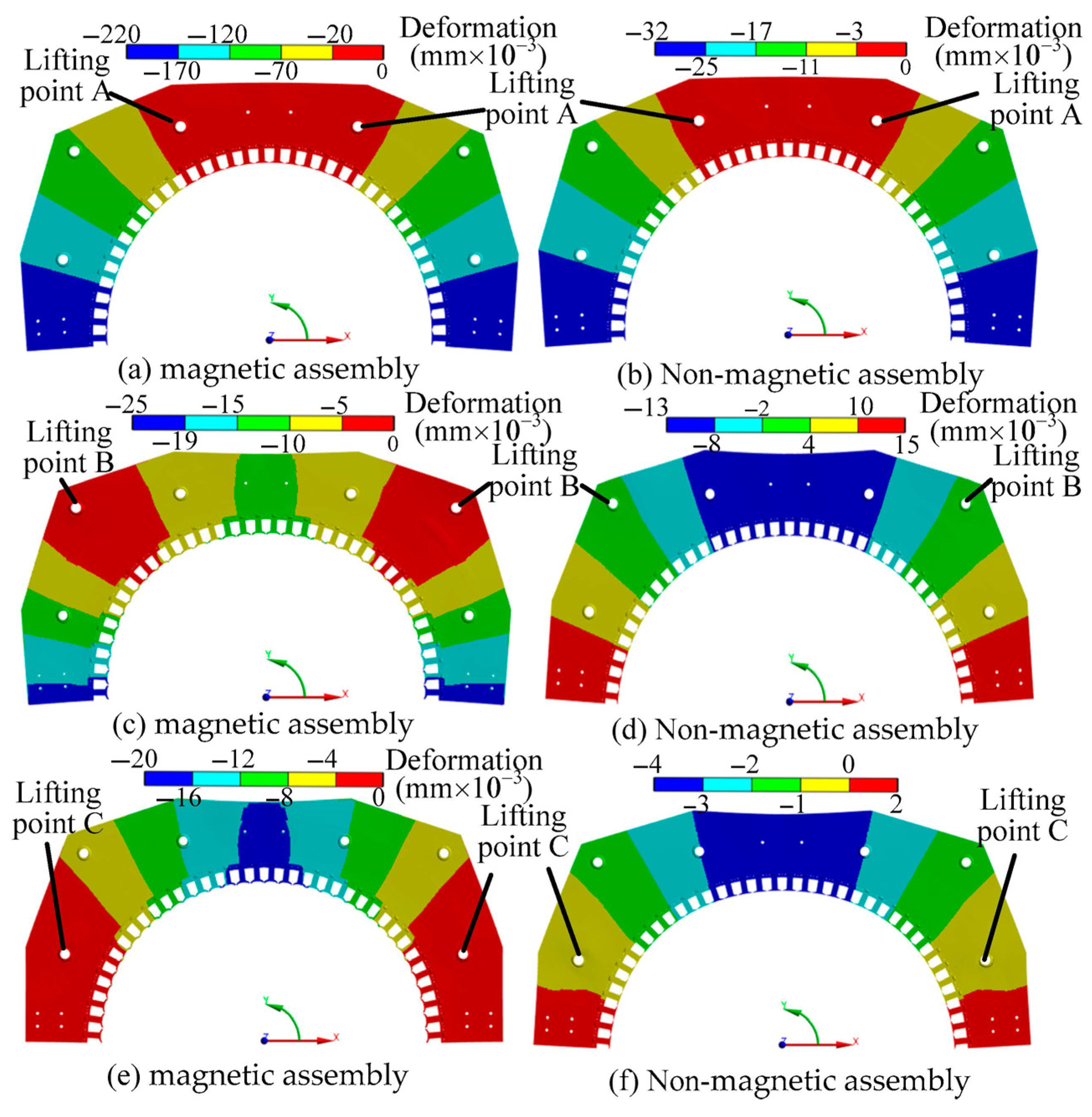
4.2. Stator Deformation Analysis at Different Lifting Positions
4.3. Mechanical Analysis of the Stator During Centering
5. Construction and Analysis of Air Gap Adjustment Device
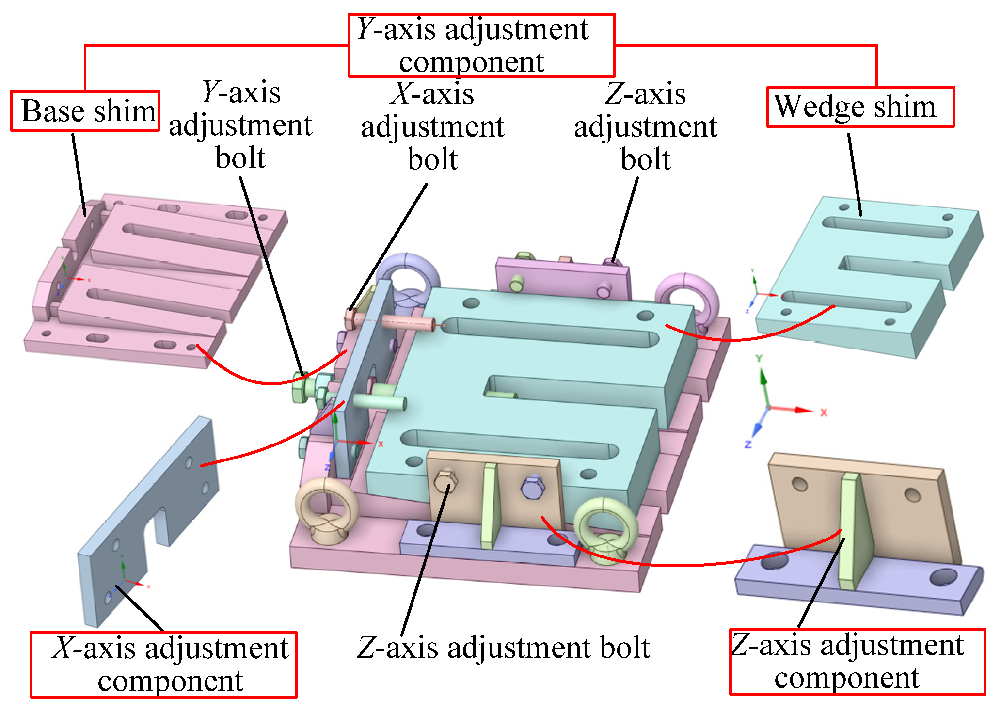
5.1. Construction of Air Gap Adjustment Device
5.2. Mathematical Model of Air Gap Adjustment Device
- (1)
- Non-magnetic adjustment
- (2)
- Magnetic adjustment
5.3. Analysis of Mechanical Properties of Air Gap Adjustment Device
- (1)
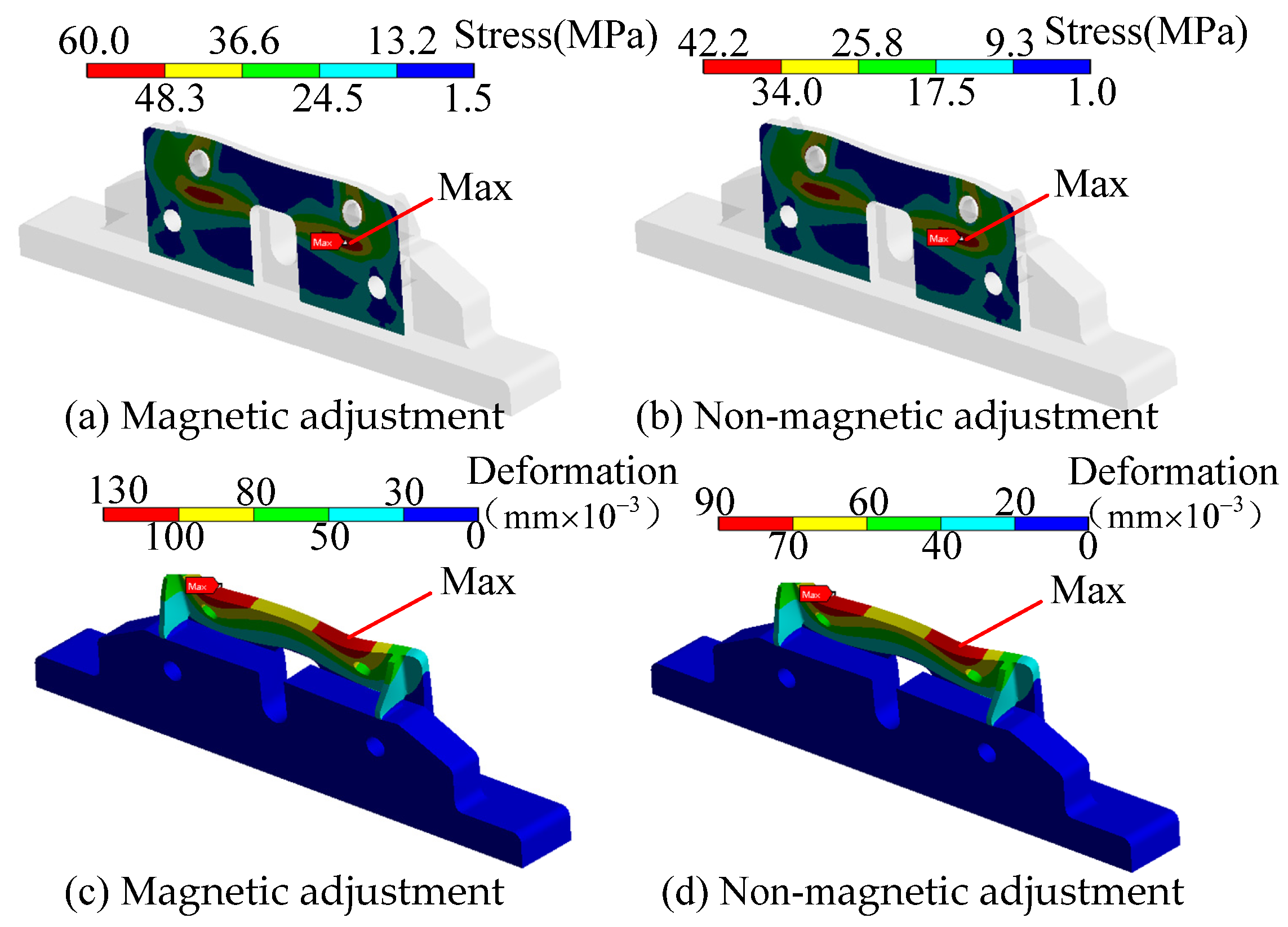
- Mechanical performance analysis of X-axis adjustment component
- (2)
- Mechanical performance analysis of Y-axis adjustment component
- (3)
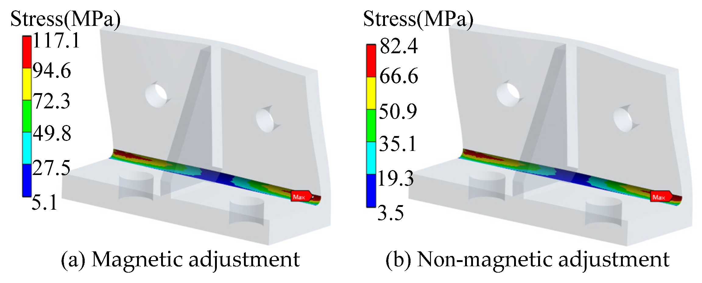
- Mechanical performance analysis of Z-direction adjustment component
6. Result Discussion

| Component | Assembled State | Force /kN | Stress /MPa | Deformation /mm × 10−3 |
|---|---|---|---|---|
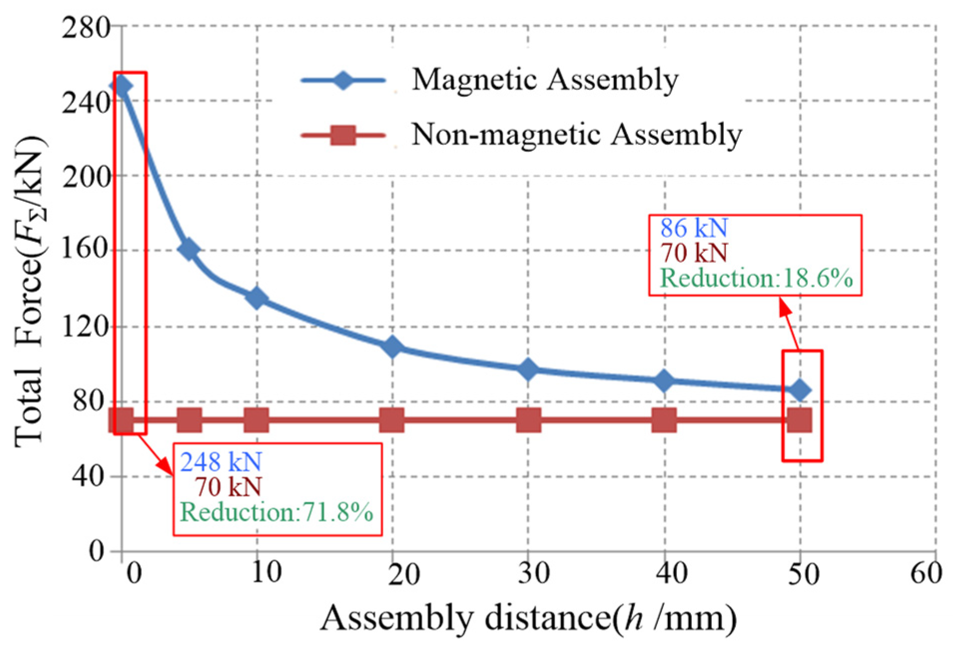
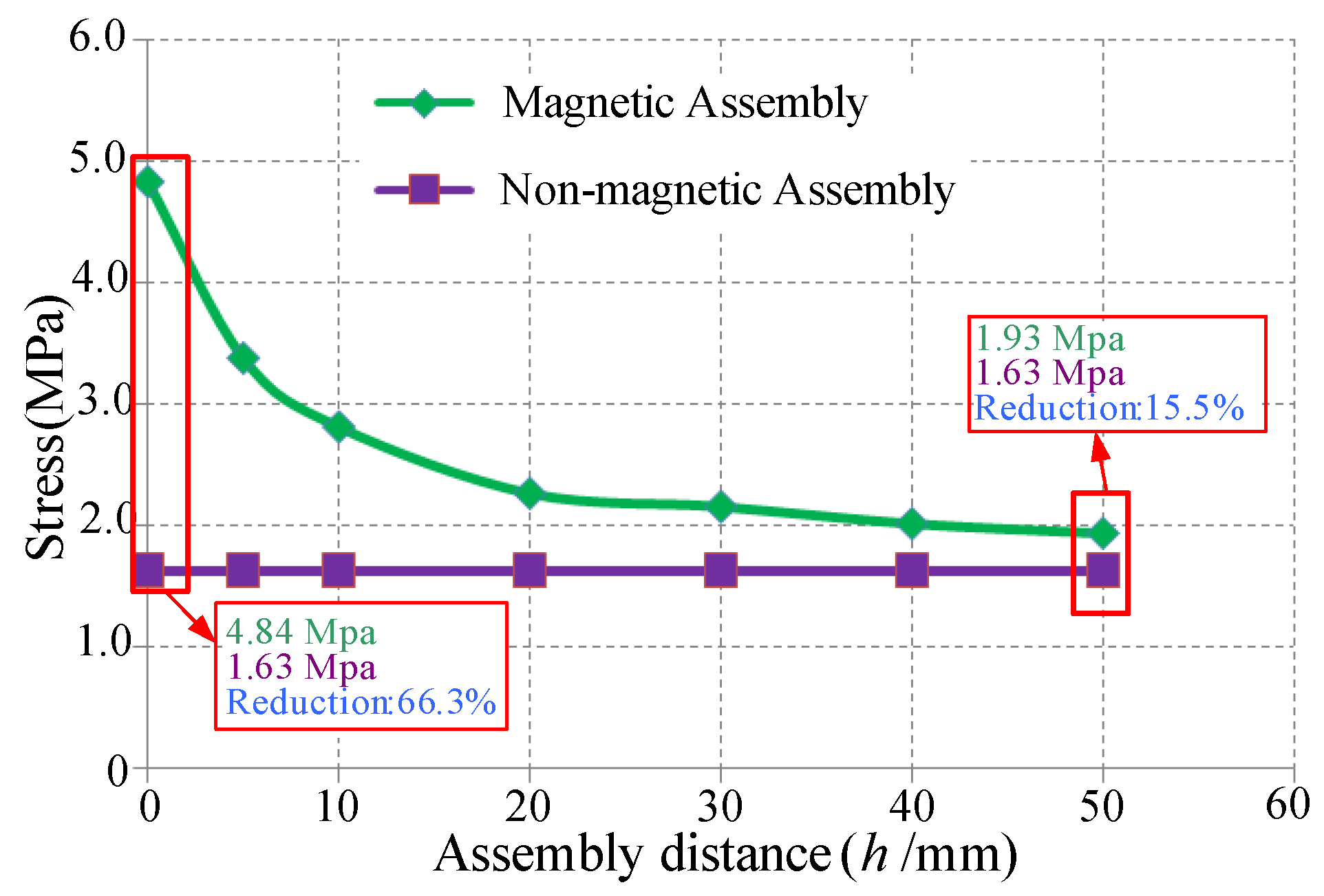
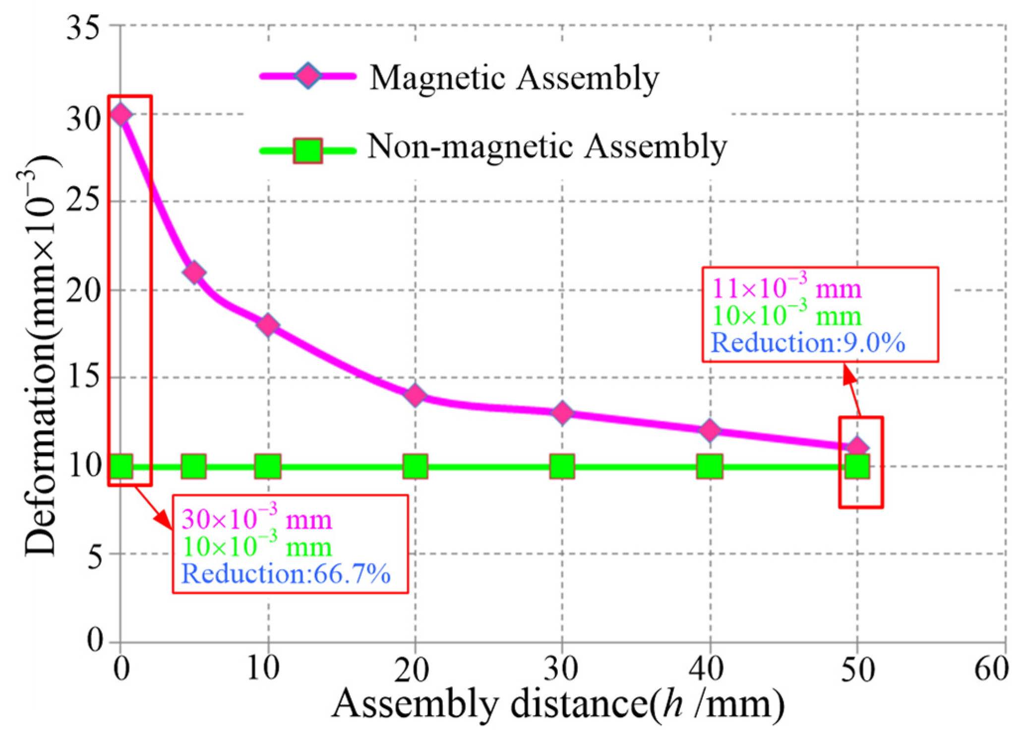
| Stator | Non-magnetic assembly | 70.0 | 1.6 | 10.0 |
| Magnetic assembly | 248.0 | 4.8 | 30.0 | |
| Stator | Non-magnetic centering | 170.0 | 1.4 | 12.8 |
| Magnetic centering | 313.0 | 8.0 | 30.2 | |
| X-direction adjustment | Non-magnetic adjustment | 34.0 | 42.2 | 90.0 |
| Magnetic adjustment | 62.6 | 60.0 | 130.0 | |
| Y-direction adjustment | Non-magnetic adjustment | 49.3 | 88.9 | 185.0 |
| Magnetic adjustment | 116.9 | 125.8 | 231.0 | |
| Z-direction adjustment | Non-magnetic adjustment | 34.0 | 82.4 | 120.0 |
| Magnetic adjustment | 62.6 | 117.1 | 170.0 |
7. Prototype and Assembly
8. Conclusions
- (1)
- A post-assembly permanent magnet installation technique based on non-magnetic principles is proposed. By deferring the magnet mounting to the final stage of motor assembly, this innovative approach effectively eliminates the magnetic attraction issues between the stator and rotor encountered in conventional methods. The implementation results demonstrate a remarkable 71.8% reduction in the total assembly load, significantly simplifying the assembly process while enhancing operational safety.
- (2)
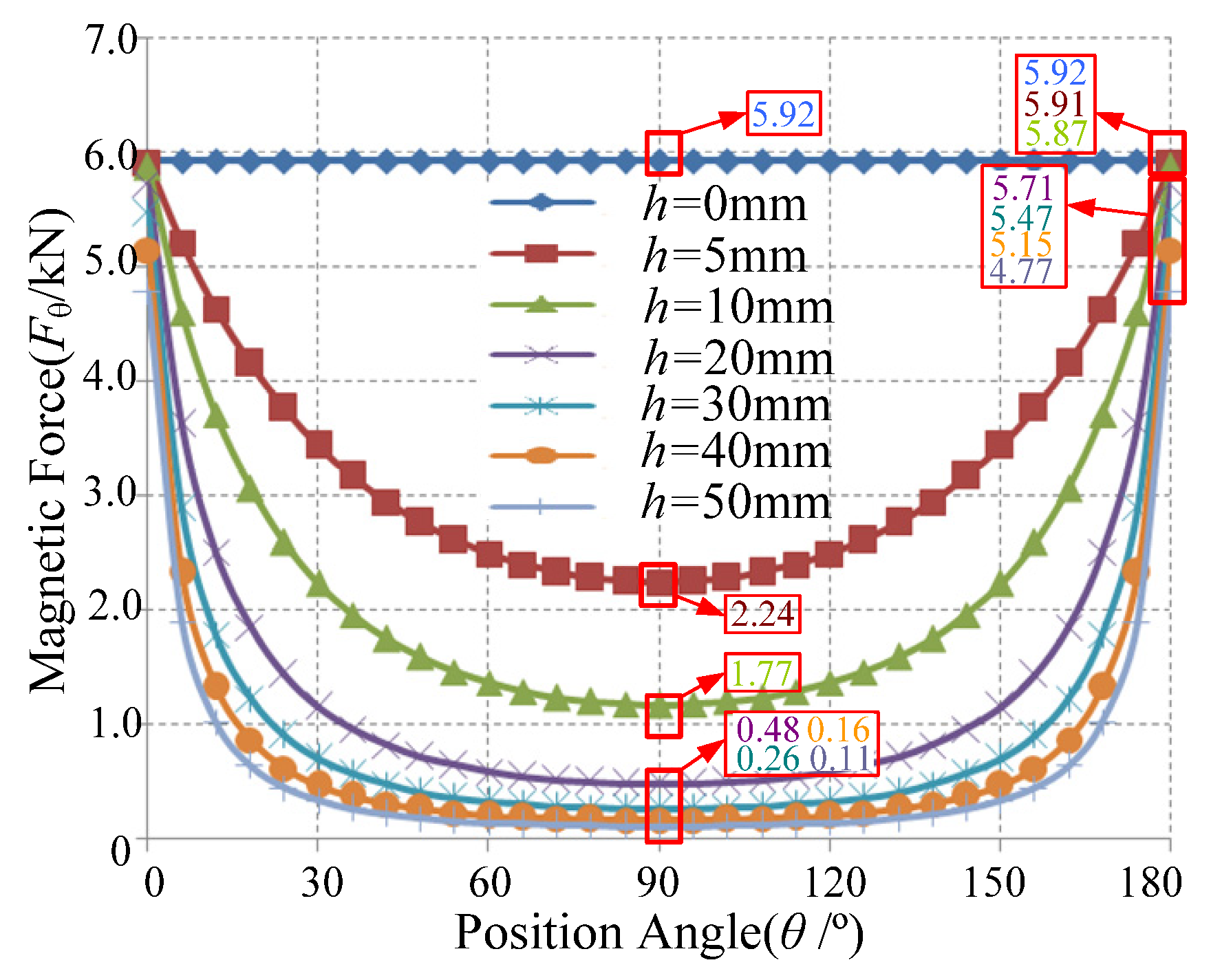
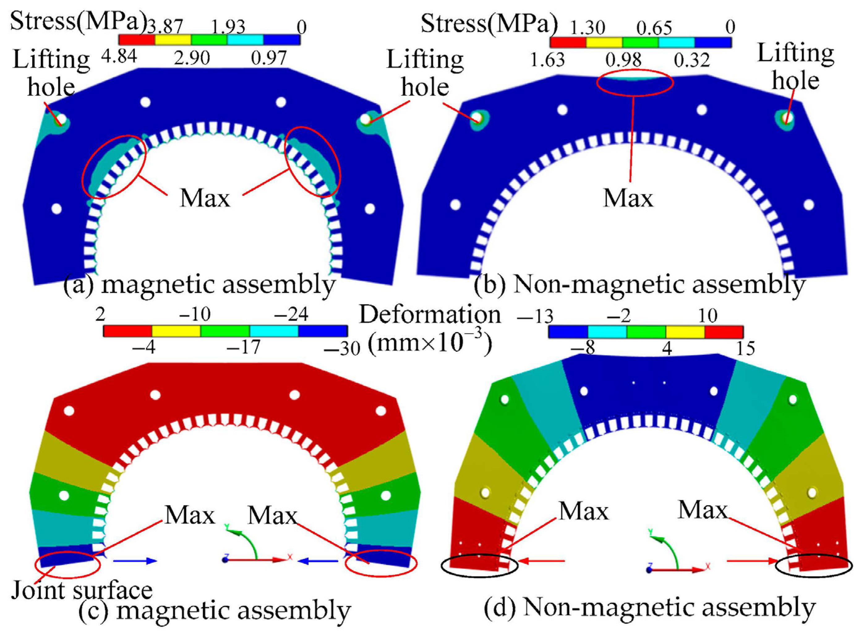
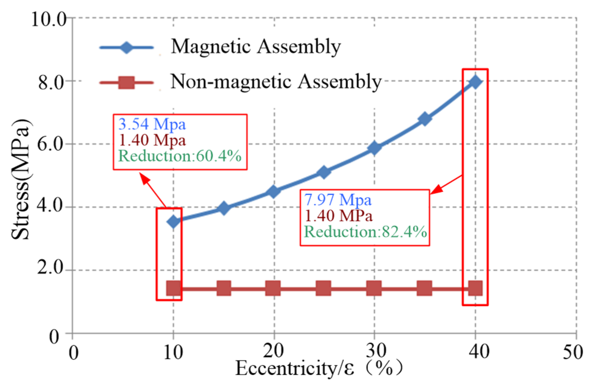
- By comparing the mechanical characteristics of magnetic and non-magnetic assembly, it is confirmed that the stress and deformation of the motor stator under non-magnetic assembly are significantly reduced. The maximum stress in the assembly stage is reduced by 66.3%, and the maximum deformation is reduced by 66.7%. The adjustment load in the air gap adjustment stage is not affected by the amount of eccentricity, and the stress and deformation increase with the growth of eccentricity. When the eccentricity is 40%, the maximum stress of the stator is reduced by 82.4%, and the maximum deformation is reduced by 57.6%. The maximum stress and deformation of each component of the air gap adjustment device during the non-magnetic adjustment stage are all reduced by about 30%.
- (3)
- The non-magnetic assembly process, combined with an air gap adjustment device, significantly reduces the on-site assembly difficulty of the PMIM for ball mills, providing a feasible technical solution for the assembly of large permanent magnet integrated motors.
- (4)
- Currently, the process technology for assembling 210 kW and 24 r/min and 540 W and 24 r/min ball mill permanent magnet motors has been successfully completed. The author’s future research in this field is anticipated to explore the scalability limits of motor size, particularly focusing on larger input power scales. Additionally, this paper did not consider the influence of motor axial eccentricity on the X-direction regulation; this aspect will be addressed in future work.
Author Contributions
Funding
Institutional Review Board Statement
Informed Consent Statement
Data Availability Statement
Conflicts of Interest
Nomenclature
| Gs | gravity of upper stator |
| GS1 | gravity of upper and lower stators |
| m1 | mass of upper and lower stators |
| m2 | mass of wedge shim |
| P | any point on inner surface of upper stator |
| RS | stator inner radius |
| Rr | rotor outer radius |
| θ | angle between point P and X-axis |
| h | mating interface gap between upper and lower stators |
| B0 | air gap magnetic flux density when air gap is uniform |
| Bg(θ) | air gap magnetic flux density at any arbitrary point on upper stator |
| g | acceleration of gravity |
| g0 | air gap value when air gap is uniform |
| g(θ) | air gap value at any arbitrary point on upper stator |
| P(θ) | magnetic pull force at point P |
| Py(θ) | magnetic pull force along Y-axis at point P |
| total magnetic pull force along Y-axis | |
| total stator load, during magnetic assembly ( = + Gs), and during non-magnetic assembly ( = Gs) | |
| total load that needs to be overcome in air gap with magnetic adjustment | |
| unbalanced magnetic pull | |
| friction resistance force of X-axis adjustment component during non-magnetic adjustment | |
| friction resistance force of Z-axis adjustment component during non-magnetic adjustment | |
| friction resistance force of Y-axis adjustment component during non-magnetic adjustment (downward) | |
| friction resistance force of Y-axis adjustment component during non-magnetic adjustment (upward) | |
| friction resistance force of X-axis adjustment component during magnetic adjustment | |
| friction resistance force of Z-axis adjustment component during magnetic adjustment | |
| friction resistance force of Y-axis adjustment component during magnetic adjustment (downward) | |
| friction resistance force of Y-axis adjustment component during magnetic adjustment (upward) | |
| L | length of stator core |
| ε | eccentricity of motor |
| μ | coefficient of sliding friction (μ = 0.2) |
| μ0 | vacuum permeability (μ0 = 4π × 10−7 H/m) |
References
- Xu, Y.Y.; Zhang, B.Y.; Feng, G.H. Analysis of Unwinding Stator Module Combined Permanent Magnet Synchronous Machine. IEEE Access 2020, 8, 191901–191909. [Google Scholar] [CrossRef]
- Niu, Y.L.; Zahng, B.Y.; Pei, Z. Stress analysis and optimization of transmission structure of permanent magnet direct drive ball mill. In Proceedings of the International Conference on Mechanisms and Robotics (ICMAR 2022), Zhuhai, China, 25–27 February 2022. [Google Scholar] [CrossRef]
- Xu, Y.Y.; Zhang, B.Y.; Feng, G.H. Electromagnetic Design and Thermal Analysis of Module Combined Permanent Magnet Motor with Wrapped Type for Mine Ball Mil. IET Electr. Power Appl. 2022, 16, 139–157. [Google Scholar] [CrossRef]
- Xu, Y.Y.; Zhang, B.Y.; Feng, G.H. Research on Efficiency Optimal Torque Distribution of Stator Module Combined Permanent Magnet Synchronous Machine. IET Electron. Power Appl. 2022, 16, 236–247. [Google Scholar] [CrossRef]
- Qiu, X.; Bai, J.; Sui, Y.; Xiao, Q.; Li, G.; Liu, Y. Design and Analysis of a Free-Piston PM Linear Motor Considering the Influence of Processing and Assembly. In Proceedings of the 2023 26th International Conference on Electrical Machines and Systems (ICEMS), Zhuhai, China, 5–8 November 2023; pp. 4909–4913. [Google Scholar] [CrossRef]
- Chen, M.; Zhang, B.; Li, H.; Gao, X.; Wang, J.; Zhang, J. Lifetime Prediction of Permanent Magnet Synchronous Motor in Selective Compliance Assembly Robot Arm Considering Insulation Thermal Aging. Sensors 2024, 24, 3747. [Google Scholar] [CrossRef] [PubMed]
- Matejić, M.; Matejić, M.; Miletić, I.; Marić, D.; Milojević, S.; Stojanović, B. Efficiency Calculation of Cycloid Reducer with Plastic Meshing Elements. Tehnički Vjesnik 2025, 32, 748–755. [Google Scholar] [CrossRef]
- Wu, S.; Li, Z.; Tong, W. Research on thermal calculation and end winding heat conduction optimization of low speed high torque permanent magnet synchronous motor. CES Trans. Electr. Mach. Syst. 2023, 7, 397–403. [Google Scholar] [CrossRef]
- Hu, Y.; Li, L.; Guo, W.; Wang, S. Study on the Rotor Strength of High-Speed Permanent Magnet Motor Considering the Influence of Assembly Pressing Force. Symmetry 2021, 13, 2161. [Google Scholar] [CrossRef]
- Lee, C.K.; Kwon, B.I.; Kim, B.T.; Woo, K.I.; Han, M.G. Analysis of magnetization of magnet in the rotor of line start permanent magnet motor. IEEE Trans. Magn. 2003, 39, 1499–1502. [Google Scholar] [CrossRef]
- Lee, C.K.; Kwon, B.I. Study in the post-assembly magnetization method of permanent magnet motors. Int. J. Appl. Electromagn. Mech. 2004, 20, 125–131. [Google Scholar] [CrossRef]
- Lee, C.K.; Kwon, B.I. Design of post-assembly magnetization system of line start permanent-magnet motors using FEM. IEEE Trans. Magn. 2005, 41, 1928–1931. [Google Scholar]
- Hsieh, M.F.; Hsu, Y.C.; Dorrell, D.G. Design of Large-Power Surface-Mounted Permanent-Magnet Motors Using Postassembly Magnetization. IEEE Trans. Ind. Electron. 2010, 57, 3376–3384. [Google Scholar] [CrossRef]
- Hsieh, M.F.; Hsu, Y.C.; Chen, P.T. Analysis and Experimental Study of Permanent Magnet Machines with In-Situ Magnetization. IEEE Trans. Magn. 2013, 49, 2351–2354. [Google Scholar] [CrossRef]
- Wang, Q.; Ding, H.; Zhang, H.; Lv, Y.; Guo, H.; Li, L. Study of a Post-Assembly Magnetization Method of a V-Type Rotor of Interior Permanent Magnet Synchronous Motor for Electric Vehicle. IEEE Trans. Appl. Supercond. 2020, 30, 5206205. [Google Scholar] [CrossRef]
- Fu, W.N.; Chen, Y. A Post-Assembly Magnetization Method for a Line-Start Permanent-Magnet Motor. IEEE Trans. Appl. Supercond. 2016, 26, 2535968. [Google Scholar] [CrossRef]
- Zhu, Z.-A.; Wang, Y.-C.; Qin, X.-F.; Yao, L.; Gyselinck, J.; Shen, J.-X. Optimal Design Method of Post-Assembly Magnetizing Device with Field–Circuit Coupling Analysis. Actuators 2023, 12, 383. [Google Scholar] [CrossRef]
- Kwon, S.-J.; Lee, B.-H.; Kim, K.-S.; Jung, J.-W. Design Process of Post-Assembly 3-Times Magnetizer for 10-Poles of Flux Concentrated Rotor Considering Eddy Current Effect. IEEE Access 2023, 11, 34476–34485. [Google Scholar] [CrossRef]
- Hyun-Soo, S.; Tak, J.; Hyun-Woo, J.; Ju, L.; Dong-Woo, K. Design of 3-Times Magnetizer and Rotor of Spoke-Type PMSM Considering Post-Assembly Magnetization. IEEE Trans. Magn. 2017, 53, 2707593. [Google Scholar] [CrossRef]
- Lv, Y.; Wang, G.; Li, L. Post-assembly magnetization of a 100 kW high speed permanent magnet rotor. Rev. Sci. Instrum. 2015, 86, 034706. [Google Scholar] [CrossRef] [PubMed]
- Seol, H.-S.; Kim, J.-Y.; Liu, H.-C.; Kang, D.-W.; Lee, J. Design Strategy of Magnetizer for Post-Assembly Magnetization of Spoke-Type Ferrite Magnet Motor. J. Electron. Mater. 2018, 48, 1368–1374. [Google Scholar] [CrossRef]
- Tu, Z.; Lv, Y.; Li, X.; Xu, W.; Peng, T.; Han, X.; Ding, H.; Li, L. Design and Experiment of Post-assembly Magnetization System for a 160-kW Interior Permanent-magnet Motor. IEEE Trans. Appl. Supercond. 2024, 34, 3364132. [Google Scholar] [CrossRef]


| Parameter | Value | Parameter | Value |
|---|---|---|---|
| Rated power | 210 kW | Continuous speed | 24 r/min |
| Outer diameter of rotor | 2724 mm | Slots/poles | 72–60 |
| Inner diameter of rotor | 2550 mm | Air gap length | 8 mm |
| Thickness of PM | 30 mm | Density of rotor | 7850 kg/m3 |
| Width of PM | 105 mm | Rotor core length | 300 mm |
Disclaimer/Publisher’s Note: The statements, opinions and data contained in all publications are solely those of the individual author(s) and contributor(s) and not of MDPI and/or the editor(s). MDPI and/or the editor(s) disclaim responsibility for any injury to people or property resulting from any ideas, methods, instructions or products referred to in the content. |
© 2025 by the authors. Licensee MDPI, Basel, Switzerland. This article is an open access article distributed under the terms and conditions of the Creative Commons Attribution (CC BY) license (https://creativecommons.org/licenses/by/4.0/).
Share and Cite
Gao, J.; Han, X.; An, Z.; Yu, Z. Non-Magnetic Assembly Technology and Mechanical Performance Analysis of Permanent Magnet Integrated Motor for Ball Mills. Energies 2025, 18, 3730. https://doi.org/10.3390/en18143730
Gao J, Han X, An Z, Yu Z. Non-Magnetic Assembly Technology and Mechanical Performance Analysis of Permanent Magnet Integrated Motor for Ball Mills. Energies. 2025; 18(14):3730. https://doi.org/10.3390/en18143730
Chicago/Turabian StyleGao, Jun, Xueyan Han, Zhongliang An, and Zhanyang Yu. 2025. "Non-Magnetic Assembly Technology and Mechanical Performance Analysis of Permanent Magnet Integrated Motor for Ball Mills" Energies 18, no. 14: 3730. https://doi.org/10.3390/en18143730
APA StyleGao, J., Han, X., An, Z., & Yu, Z. (2025). Non-Magnetic Assembly Technology and Mechanical Performance Analysis of Permanent Magnet Integrated Motor for Ball Mills. Energies, 18(14), 3730. https://doi.org/10.3390/en18143730