Article

Sensor-Reduced Active Power Decoupling Method for Single-Phase Rectifiers

1
Huizhou Power Supply Bureau of Guangdong Power Grid Co., Ltd., Huizhou 516000, China
2
School of Automation, Central South University, Changsha 410083, China
*
Author to whom correspondence should be addressed.
Energies 2025, 18(14), 3711; https://doi.org/10.3390/en18143711
Submission received: 22 May 2025 / Revised: 5 July 2025 / Accepted: 10 July 2025 / Published: 14 July 2025

Abstract

Active power decoupling (APD) technology demonstrates significant advantages in addressing the mismatched second-order ripple power issue in single-phase rectifiers. However, conventional methods typically require additional voltage or current sensors to achieve precise decoupling control, thereby increasing the cost of the decoupling circuit. To reduce costs and simplify the control system, a sensor-reduced decoupling control method is proposed, with its key advantages highlighted in three aspects: First, the proposed method operates by replacing actual sampled variables with designed reference values, reducing the number of sensors—only the DC bus voltage information is required for operation. Second, the sensor-reduced control scheme is designed based on Lyapunov stability conditions and ensures system stability. Third, virtual impedance produces the reference current of the decoupling circuit, which eliminates grid signal interaction and simplifies control. Simulation and experimental results validate the effectiveness and feasibility of the proposed method.

1. Introduction

The single-phase rectifier is one of the most commonly used power electronic devices, with extensive applications in industrial, commercial, and residential fields [1,2,3]. However, there is an inherent second-order ripple power mismatch between the AC and DC sides of the single-phase rectifier. This ripple power leads to many adverse effects. For example, in applications such as LED lighting drivers and photovoltaic inverters, the ripple power may lead to fluctuations in the DC-side voltage/current, resulting in low-frequency flickering in LEDs [4] or reducing the Maximum Power Point Tracking (MPPT) efficiency of photovoltaic panels [5]. To address the ripple power issue, large electrolytic capacitors are typically used to absorb pulsating power (passive power decoupling), but they increase the system volume and reduce reliability [6,7]. As an alternative solution, Active Power Decoupling (APD) has gained widespread attention from researchers and engineers in recent years [8,9]. APD circuits use small capacitors with large voltage fluctuations to buffer second-order ripple power, greatly reducing electrolytic capacitor requirements.
Although APD technology demonstrates significant advantages in addressing the mismatched second-order pulsating power in single-phase rectifiers, it also introduces new challenges. For instance, the implementation of APD typically requires additional voltage/current sensors. This is because the decoupling circuit increases the system order, requiring additional state variable measurements for control. For example, Reference [10] employed a total of six sensors to realize its designed feedback linearization-based decoupling control method. However, the excessive use of sensors conflicts with key technical metrics such as power density, cost efficiency, and system reliability [8,9]. An increased number of sensors raises the system volume and economic costs, making their extensive use impractical for applications with stringent cost and space constraints, such as LED lighting [11]. Moreover, under non-ideal operating conditions and harsh environments (e.g., high temperature, humidity, and mechanical vibration), the reliability of sensing devices may degrade.
Recently, research on APD control with a reduced sensor count has attracted scholars’ attention. Current sensor reduction decoupling control methods are primarily divided into two categories: observer-based approaches and nonlinear controller design methods. The observer-based method employs observers to estimate variables requiring sampling and utilizes the results for feedback control. The literature [12,13,14,15] analyzes voltage sensor-reduced control methods based on algebraic observers, which transform the state-space average model into a series of observers to estimate the decoupling capacitor voltage. In addition to algebraic observers, the literature [16] proposes a voltage sensor-reduced Multiple Model Predictive Control (MMPC) method for Buck-type decoupling circuits. This method achieves the sensor-reduced prediction of decoupling voltage by reconstructing the dynamic model based on Euler approximation. However, these observer algorithms suffer from noise sensitivity and computational complexity, and they do not fundamentally eliminate the control strategy’s dependence on decoupling capacitor voltage information. Unlike observer-based methods, the nonlinear controller design approach for sensor reduction does not require decoupling capacitor voltage feedback in the control process. The literature [17,18] proposes an optimized modulation strategy that eliminates the need for prior decoupling capacitor voltage information, using ideal voltage reference values as modulation signals to achieve sensor reductions. However, this method requires Linear Matrix Inequality (LMI) to calculate the relevant control parameters when generating voltage reference signals and relies on complex H∞ theory to prove system stability, thereby increasing the system’s computation and application complexity. The literature [19,20] predicts the decoupling capacitor energy and voltage based on energy relationships to realize sensor-reduced control, but it requires two error correctors to compensate for both control accuracy and parameter robustness.
However, all the aforementioned sensor reduction decoupling control methods require interaction with the rectifier to obtain the grid-side voltage, current, and phase angle information, inevitably necessitating a centralized controller and higher-cost, real-time communication technologies. In this study, a Lyapunov equation-based APD control method is proposed. This method ensures stability while eliminating grid-side information dependence. Consequently, it achieves APD control with minimal sensors.
The structure of this paper is organized as follows: Section 2 proposes a sensor-reduced decoupling control strategy based on the Lyapunov equation; Section 3 designs the current reference signal reduction scheme using a virtual impedance approach; Section 4 validates the effectiveness of the proposed method through simulations and experiments; and Section 5 provides a concluding summary of the entire study.

2. Sensor-Reduced Control Strategy Based on Lyapunov Equation

This section analyses and proposes a Lyapunov equation-based sensor-reduced decoupling control strategy. First, the working principle of the Buck-type decoupling circuit is introduced. Then, the designed reference signals are utilized to replace the original sensor measurements, thereby achieving sensor reductions. Based on Lyapunov stability theory, the required conditions for the designed signals are derived, with system stability being rigorously proven.

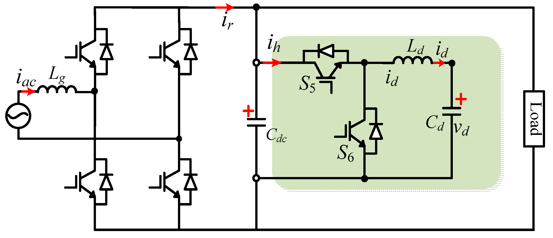
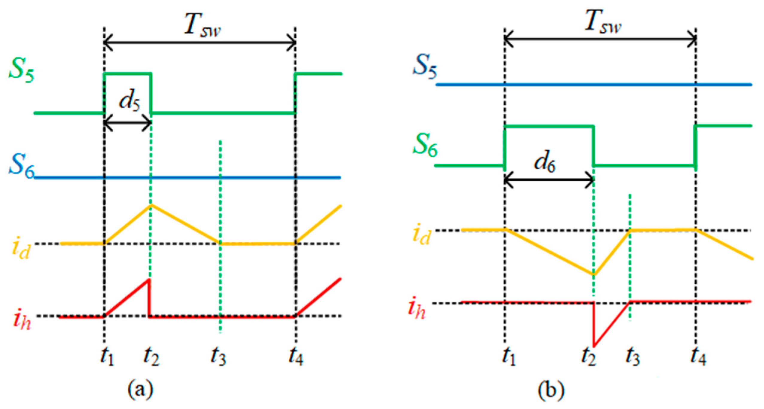
2.1. Operating Principle of Buck-Type Decoupling Circuit

Figure 1 illustrates a single-phase voltage-source rectifier with a parallel Buck-type decoupling circuit, where the Buck-based decoupling unit, consisting primarily of the decoupling inductor Ld, decoupling capacitor Cd, and switching devices S5/S6, is connected in parallel to the DC bus as an independent decoupling module.
During operation, this single-phase rectifier exhibits an inherent second-order ripple power mismatch between its input and output ports. Assuming a sinusoidal AC-side grid voltage vac and in-phase current iac, the expressions are as follows:
v a c ( t ) = 2 V a c sin ( ω t ) i a c ( t ) = 2 I a c sin ( ω t )
where Vac and Iac are the root-mean-square values of the grid voltage vac and input current iac, respectively, and ω is the grid angular frequency.
According to the instantaneous power calculation method, the AC-side power is the product of the instantaneous voltage and current, given by the following:
p a c ( t ) = V a c I a c V a c I a c   cos ( 2 ω t )
Equation (2) shows that pac(t) consists of two components: a constant term Pac and a term related to cos(2ωt). The cos(2ωt) term represents a second-order grid frequency component, whose amplitude is equal to the average power. This implies that, in addition to the DC power delivered to the load, there exists an AC-side ripple power oscillating at twice the grid frequency. This ripple power cannot be directly utilized in the circuit and is inherently determined by the characteristics of single-phase rectifiers. It will not disappear regardless of the topology or control strategy employed. The expression is given by the following:
p r i p ( t ) = V a c I a c   cos ( 2 ω t )
From the perspective of active filtering, the second-order ripple power induces low-frequency voltage/current components in the main circuit. By controlling the decoupling circuit to generate the corresponding compensating voltage/current, these low-frequency components can be cancelled, thereby maintaining a constant DC voltage/current. Therefore, under steady-state conditions, to prevent harmonic currents from flowing into the load, the decoupling circuit must counteract these harmonics. Accordingly, the reference current for the decoupling port ihref should be as follows:
i h r e f = V a c I a c 2 v d c cos ( 2 ω t + φ )
To generate the port current reference, the Buck-type decoupling circuit operates in two distinct modes: the step-down mode is defined as when ripple power is absorbed (where secondary ripple energy flows from the DC bus to the decoupling capacitor with the bus voltage exceeding the capacitor voltage), during which S5 operates at high frequency while S6 remains off; conversely, the step-up mode occurs when releasing ripple power (with second-order ripple energy transferring from the decoupling capacitor to the DC bus while maintaining the bus voltage higher than the capacitor voltage), where S6 performs high-frequency switching while S5 stays inactive. Figure 2 shows the switching signals and waveforms of id and ih in both modes.
During step-down operation, the average value of id per switching cycle derived from the state-space averaging model is as follows:
i ¯ d = d 5 2 v d c ( v d c v d ) τ v d
where τ = 2Ld/Tsw.
After obtaining the average current value, the dynamic equations for the capacitor voltage vd and current ih flowing into the decoupling unit are derived, establishing the mathematical model of the Buck-type decoupling circuit in step-down mode as follows:
v ˙ d = d 5 2 v d c ( v d c v d ) τ C d v d i ¯ h = d 5 2 ( v d c v d ) τ
Similarly, the mathematical model of the Buck-type decoupling circuit operating in step-up mode is derived as follows:
v ˙ d = d 6 2 v d c v d τ C d ( v d c v d ) i ¯ h = d 6 2 v d 2 τ ( v d c v d )

2.2. Stability-Conscious Sensor-Reduced Control Strategy Design

According to the Lyapunov stability theorem [17,18,19], system stability can be determined by analyzing a scalar energy function (commonly referred to as the Lyapunov function V(x)). Lyapunov’s direct method states that the equilibrium point is globally asymptotically stable when V(x) meets the following conditions:
(a)
V(0) = 0;
(b)
V(x) > 0, x ≠ 0;
(c)
V(x) → ∞, ||x|| → ∞;
(d)
V ˙ ( x ) < 0 , x ≠ 0.
For the system under study, the following positive definite Lyapunov function is considered:
V ( e ) = 0.5 C d e 2
where e = vdvdref, with vdref being a specified target reference whose concrete design form will be derived in the subsequent sections. Clearly, V(e) satisfies conditions (a)–(c). To ensure that condition (d) is satisfied, the derivative of Equation (8) is analyzed:
V ˙ ( e ) = C d ( v d v d r e f ) ( v ˙ d v ˙ d r e f ) = C d e e ˙
If the condition is satisfied e ˙ e < 0 , then V ˙ ( e ) < 0 . To achieve this objective, by substituting the Buck-type decoupling circuit model into the derivative expression, the following expression is obtained for step-down operation:
C d e ˙ = C d ( v ˙ d v ˙ d r e f ) = d 5 2 v d c ( v d c v d ) τ v d C d v ˙ d r e f
Since d5 serves as the control input with design degrees of freedom, it can be configured as required. In conventional control strategies, based on the system model in Equation (6), the steady-state value of d5 in step-down operation satisfies the following:
d 5 2 = τ i h r e f v d c v d
To eliminate the voltage sensor for vd and achieve stable decoupling control under a condition where vd is unknown, the control law in Equation (11) is referenced, where the expression of vd is replaced with the given signal vdref, yielding the following:
d 5 2 = τ i h r e f v d c v d r e f
To analyze system stability under this control law, Equation (12) is substituted into Equation (10) (see Appendix A), yielding the following:
C d e ˙ = v d c i h r e f v d c C d v ˙ d r e f v d v d ( v d c v d r e f ) + i h r e f v d c C d v ˙ d r e f v d r e f v d c v d r e f
Equation (13) determines the system’s stability at the equilibrium point. If condition d is satisfied in Equation (13), this control law achieves stable decoupling control without requiring vd measurement. Condition d can be reformulated as e ˙ e < 0 , where the proper design of the relationship between vdref and ihref must satisfy this requirement. To facilitate the elimination of the second term in Equation (13), the reference voltage vdref is designed to fulfil the following:
C d v ˙ d r e f v d r e f = i h r e f v d c
Substituting into (13) yields the following:
C d e ˙ = v d c i h r e f v d c i h r e f v d c v d / v d r e f v d ( v d c v d r e f ) = α e
where α = i h r e f v d c 2 v d v d r e f ( v d c v d r e f ) > 0 .
The topology of the Buck-type decoupling circuit inherently ensures that the actual decoupling capacitor voltage vd cannot exceed the DC bus voltage vdc. Consequently, the feasible range for vdref is strictly bound between 0 and vdc. Furthermore, in step-down operation, ihref remains consistently positive (as dictated by the modulation strategy). This guarantees that α will be a positive quantity, thereby satisfying condition (c). Thus, in the step-down mode, the decoupling capacitor voltage vd will asymptotically converge to its prescribed reference value vdref.
Considering the step-up operation mode of the decoupling circuit, which is analogous to the step-down mode, the actual voltage vd is similarly replaced with its reference signal vdref and the duty ratio is designed as follows:
d 6 2 = τ i h r e f ( v d c v d r e f ) v d r e f 2
Similar to the step-down analysis, step-up mode meets these conditions under control law (16) and reference (14):
C d e ˙ = C d ( v ˙ d v ˙ d r e f ) = d 6 2 v d c v d τ ( v d c v d ) C d v ˙ d r e f = α e
where α = i h r e f v d c 2 v d r e f 2 ( v d c v d ) > 0 .
In step-up operation, ihref remains consistently negative (as determined by the modulation strategy). Consequently, α′ is guaranteed to be positive, thereby satisfying condition (d). Thus, the decoupling capacitor voltage vd asymptotically converges to its prescribed reference vdref in step-up mode.
At this stage, the design of the decoupling voltage reference signal in (14) ensures system stability under the control laws specified in (12) and (16). This achieves the autonomous convergence of the decoupling capacitor voltage vd, while reducing the number of internal variable samplings required for decoupling control.

3. Current Reference Design and Control System Implementation

This chapter specifically designs the current references for sensor-reduced control based on Lyapunov equations. First, the decoupling module port current reference ihref is obtained using the virtual impedance method. Building on this, the decoupling voltage reference signal vdref required for sensor-reduced control is further refined. Ultimately, the implemented control system achieves complete independence from the AC-side information exchange with the rectifier, accomplishing the goal of minimal sensor deployment.

3.1. Virtual Impedance-Based Reference Current Design Methodology

Virtual impedance generates current references by emulating an LC resonant circuit at 2ωg. This creates a low-impedance path for second-order ripple current, diverting it from the load.
As shown in Figure 3, the equivalent admittance of the passive LC resonant circuit is as follows:
G = j ω C   | |   j ω L = j ω C 1 ω 2 L C
where L and C represent the inductance and capacitance values of the passive resonant circuit, respectively, and the resonant frequency satisfies ω r = 2 π L C .
When ω = 0, then G = 0, indicating that the resonant circuit behaves as an open circuit to the DC component in ir. When ω = 2ωg, the equivalent admittance G approaches infinity, demonstrating that the circuit acts as a short circuit to the second-order component in ir, thereby bypassing the second-order ripple current through the resonant path.
The control objective of the decoupling circuit is to ensure that the port output characteristics match those of the resonant circuit, thereby achieving an equivalent effect to the resonant circuit. Initially, based on the differential equation relationship between the port voltage and current of the resonant circuit, the transfer function relationship between the input current of the decoupling circuit port and the bus voltage can be derived:
i h ( s ) = s / L s 2 + 1 / ( L C ) v d c ( s )
Based on this, the port characteristics can be emulated. In Figure 3b, the reference current for the decoupling module port should be as follows:
i h r e f ( s ) = k r s s 2 + ω r 2 v d c ( s )
where the resonant gain kr = 1/L and the resonant angular frequency ωr = 2ωg. From Equation (20), it can be observed that the decoupling current reference based on the virtual impedance method requires only the DC bus voltage vdc as external information. The decoupling unit no longer reuses the rectifier’s information and eliminates the need for a centralized controller, which is an advantage of this method.

3.2. Overall Structure of Sensor-Reduced Control

According to the virtual impedance strategy, the reference signal ihref should be selected as follows:
i h r e f = k r s s 2 + ω r 2 v d c
To determine vdref, substitute the known expression from Equation (21) into Equation (14), which gives the following:
v d r e f = 1 C d V d 0 + i h r e f v d c d t
where V d 0 is an initial voltage integration constant.
In summary, the system control block diagram is shown in Figure 4. The rectifier adopts a classic dual-loop voltage–current control strategy to regulate the input current and maintain the average output voltage. The decoupling control uses open-loop virtual impedance to calculate the port current reference. It calculates the duty cycles using the reference voltage vdref for stable decoupling. The control diagram reveals that neither the actual decoupling inductor current id nor the decoupling capacitor voltage vd requires sampling. Moreover, the decoupling control operates without information exchange with the AC grid side of the rectifier. The entire decoupling control system only needs the DC bus voltage information, realizing decoupling control with the minimum number of sensors.

4. Qualitative and Quantitative Assessments

To verify the effectiveness of the proposed control strategy, a qualitative comparative analysis table, along with simulation and experimental platforms, was constructed. The overall control block diagram is shown in Figure 4, where the rectifier adopts a classic voltage outer-loop and current inner-loop control scheme, with the voltage outer-loop regulating the average DC bus voltage as the reference to achieve average power control. The decoupling circuit employs the proposed sensor-reduced control strategy, with the following key controller parameters: ωr = 100, kr = 50, α = 5 × 10⁻⁷.

4.1. Qualitative Comparative Analysis

The traditional capacitor decoupling and sensor-reduced decoupling control methods are selected for comparison with the proposed method in this paper. A characteristic comparison table is established in Table 1.
Through qualitative comparisons, it can be seen that the proposed method has advantages in the number of sensors, resulting in fewer fault points and higher reliability. On the other hand, the proposed method is simple to implement, requiring less parameter tuning and lower complexity.

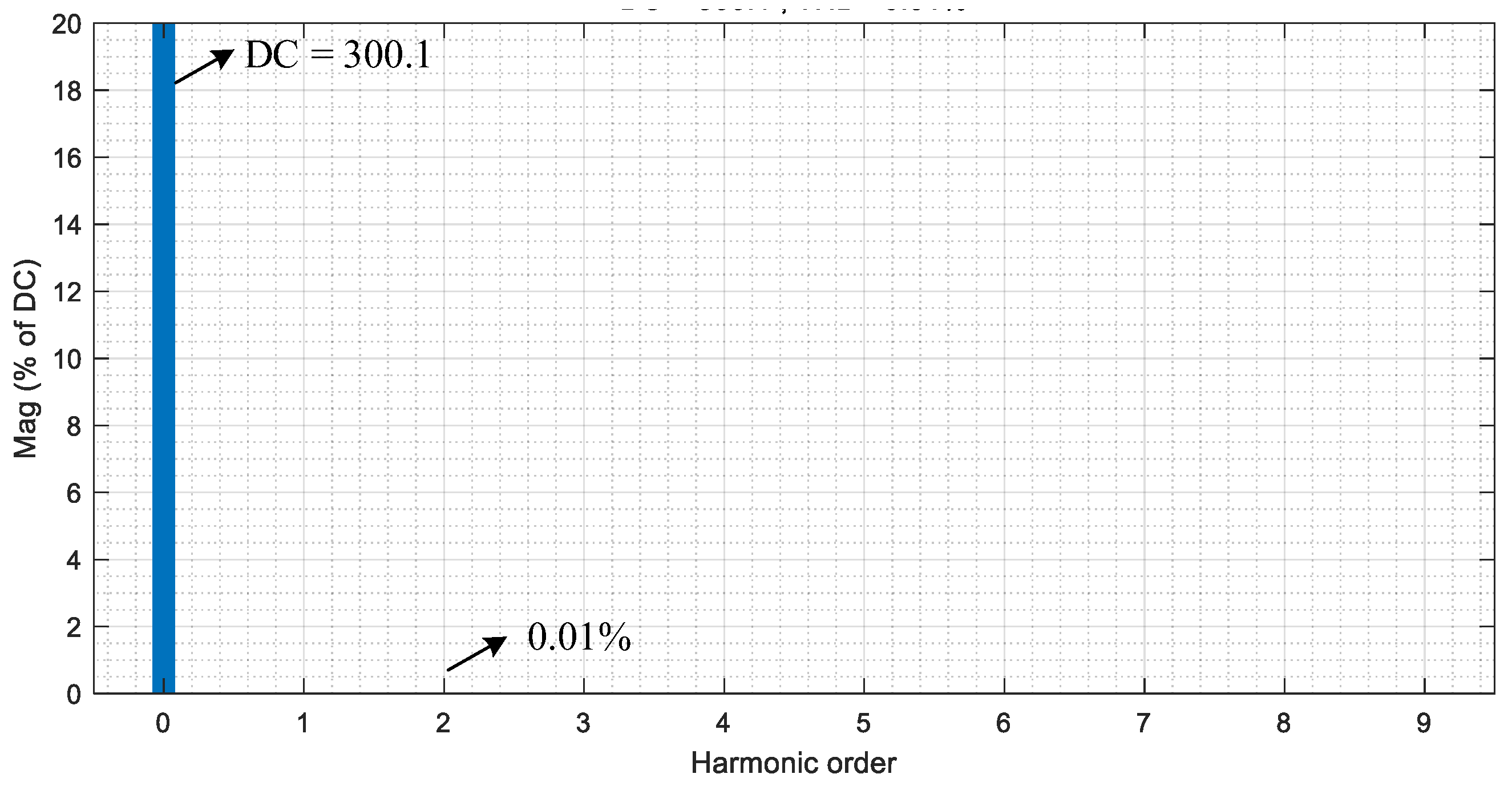
4.2. Simulation Verification and Analysis

First, a simulation model of the single-phase PWM rectifier with a parallel Buck-type decoupling circuit (shown in Figure 1) was built in the MATLAB/Simulink platform. The Buck-type decoupling unit under the control scheme illustrated in Figure 4 was then verified through a simulation, with the circuit parameters specified in Table 2.
Figure 5 presents the steady-state waveforms under the proposed control: DC bus voltage vdc, decoupling capacitor voltage vd, grid-side voltage vac, and grid-side current iac. As can be seen from the figure, the grid-side current iac is a sinusoidal wave in phase with the grid voltage, with a power factor (PF) = 0.99 and total harmonic distortion (THD) = 1.6%. Meanwhile, the bus voltage exhibits minimal fluctuations with a ripple ratio of 2.8%, meeting the IEC 61000-3-2 standard [21]. On the other hand, the decoupling capacitor voltage fluctuates at twice the grid frequency (100 Hz), with its average value stabilized at 170 V. These results verify that the proposed sensor-reduced decoupling control scheme achieves equivalent performance to conventional decoupling control methods [22] without requiring decoupling capacitor voltage sensor sampling, demonstrating both efficient and stable operation of the decoupling unit.
FFT spectral analysis was performed on the steady-state DC bus voltage waveform, yielding the voltage spectrum shown in Figure 6. The results indicate that the second-harmonic component in the DC bus voltage is merely 0.01%, demonstrating the proposed control strategy’s excellent steady-state decoupling performance.

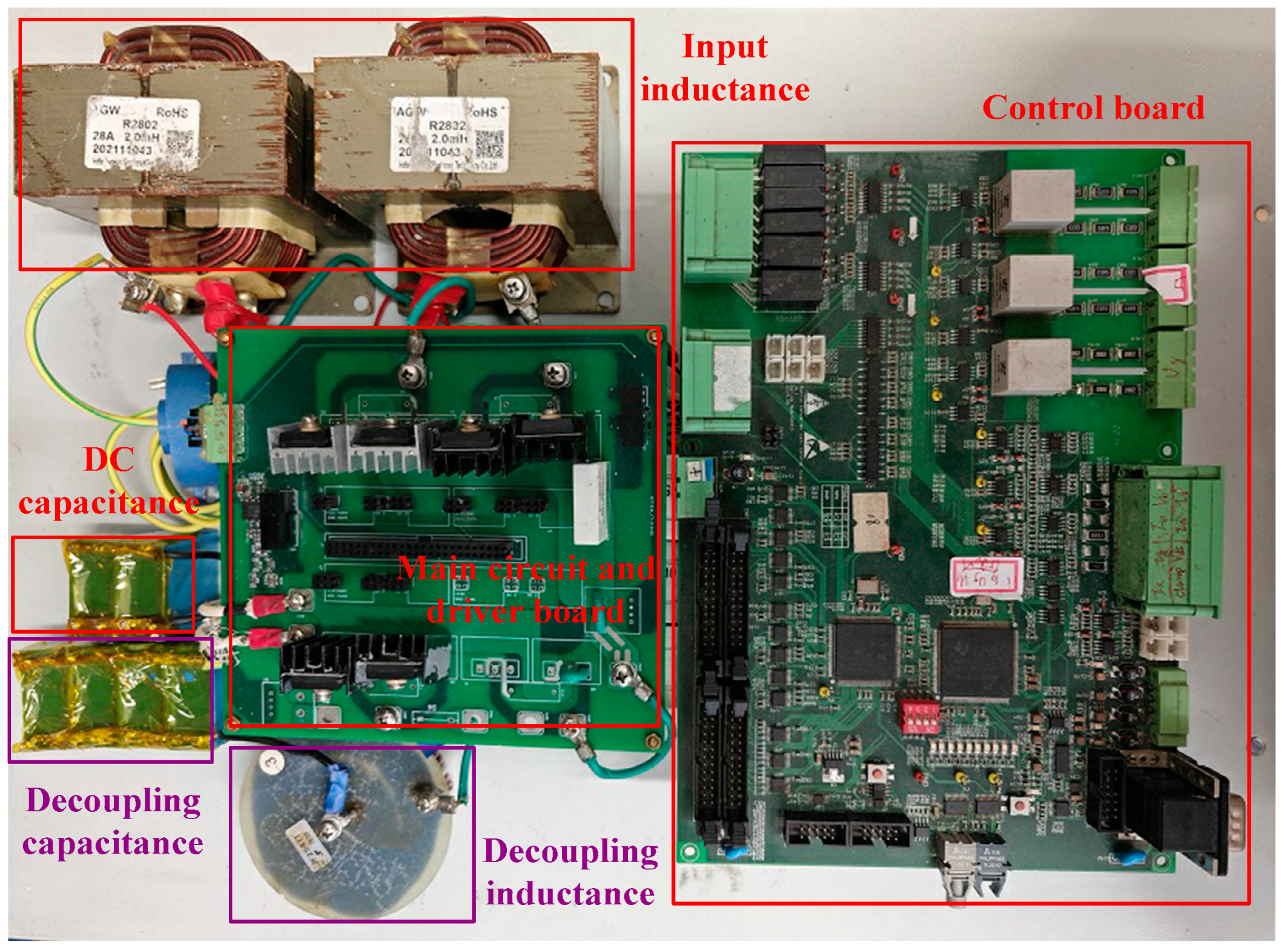
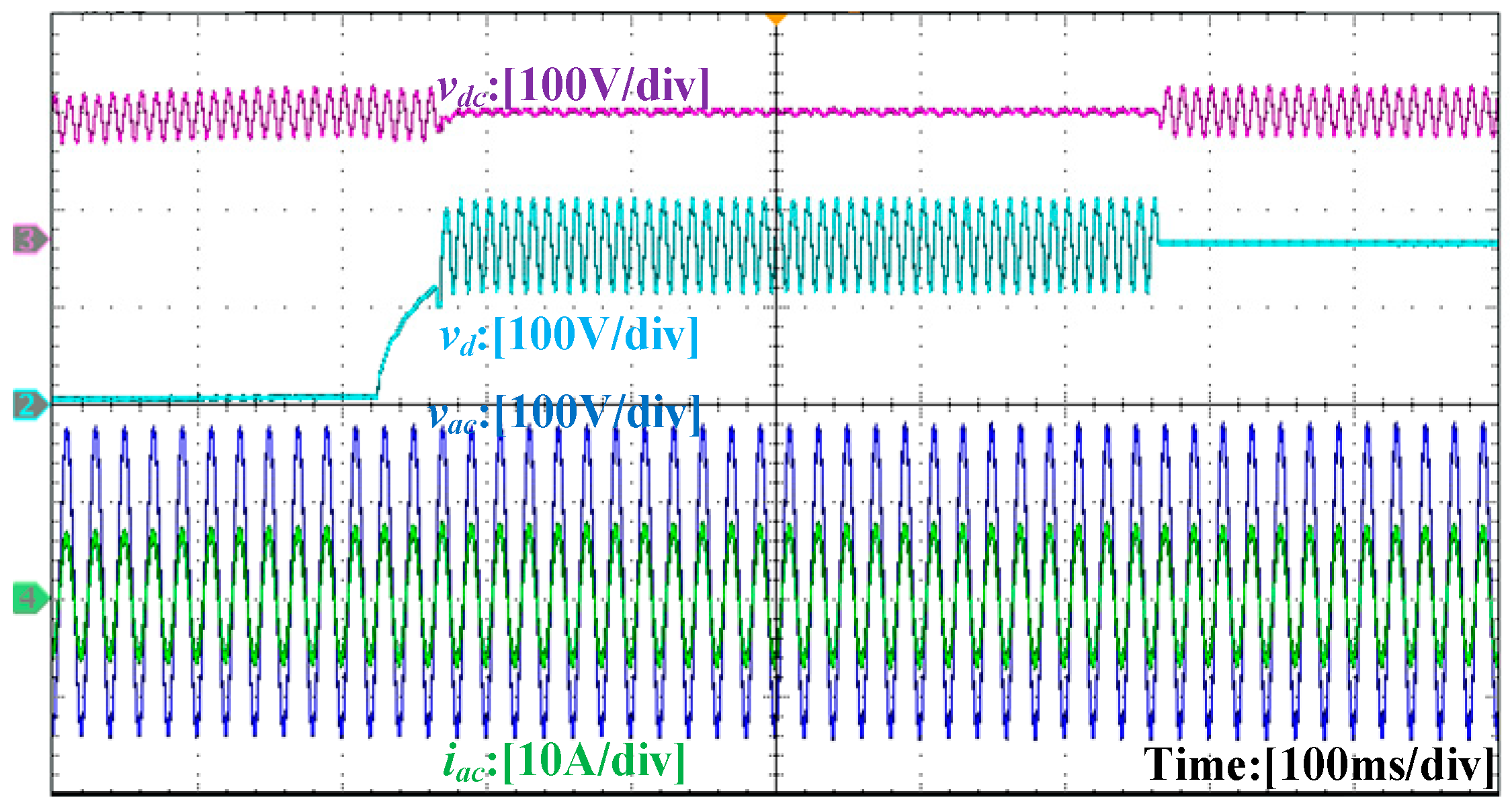
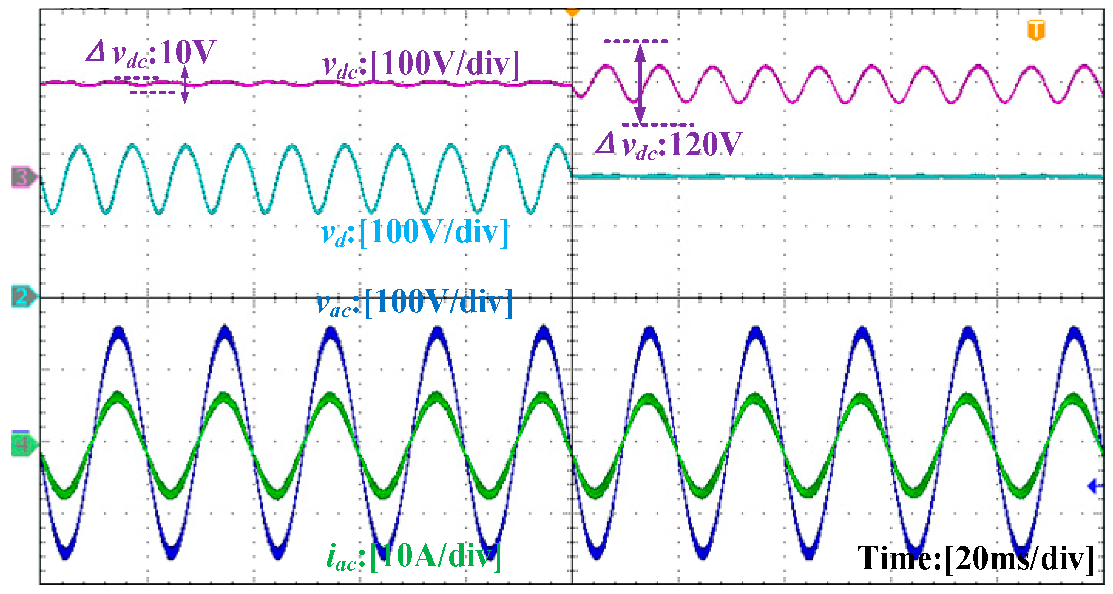
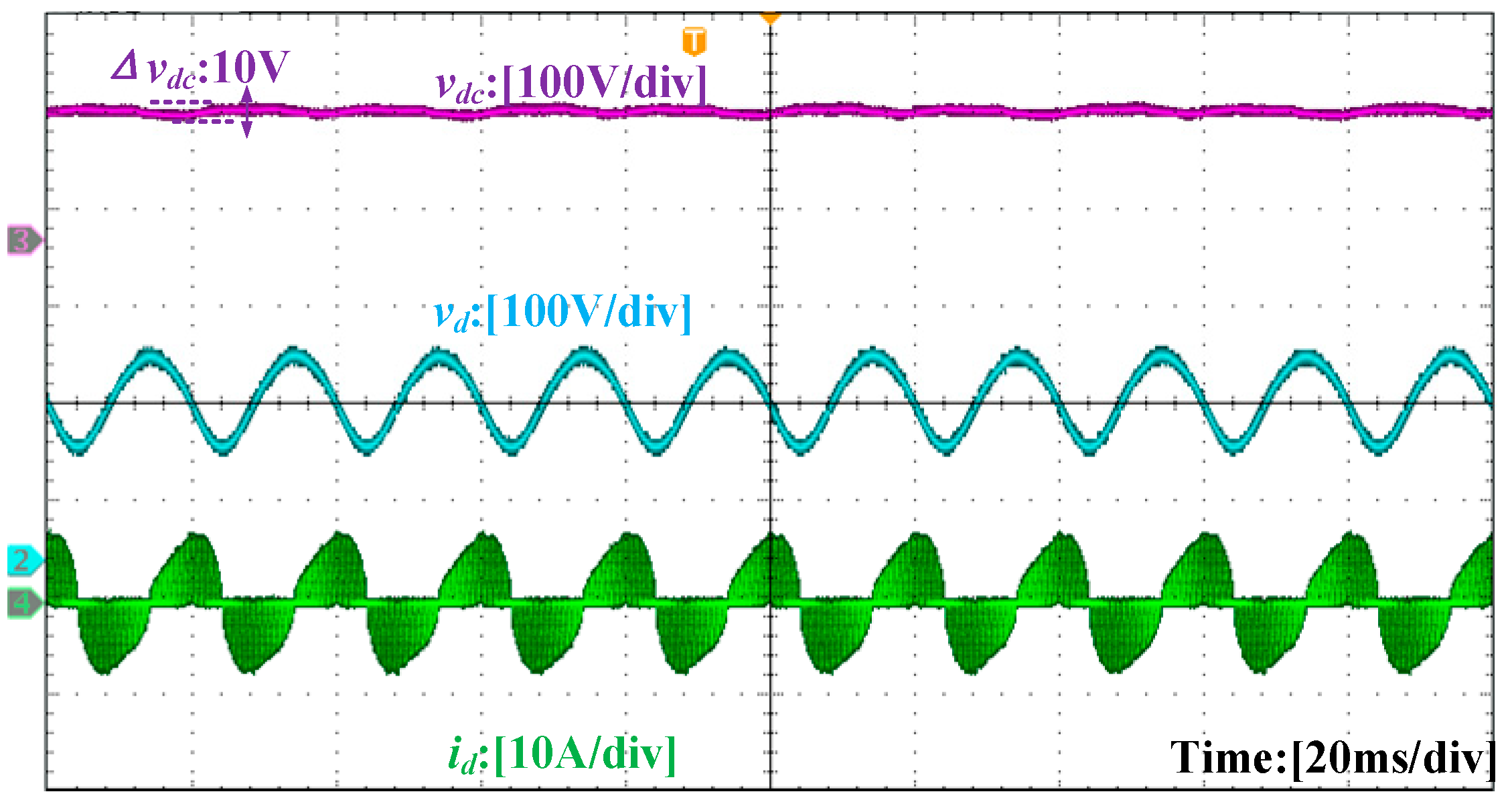
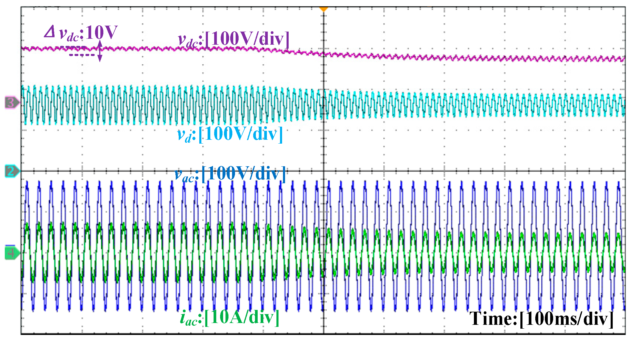
4.3. Experimental Verification and Analysis

Building upon the simulation verification, experimental validation was conducted using the test platform shown in Figure 7.
The experimental waveforms are shown in Figure 8, Figure 9, Figure 10, Figure 11 and Figure 12, with Figure 8 displaying the overall operational waveforms of the system, including the decoupling capacitor voltage vd, DC bus voltage vdc, input voltage vac, and input current iac in sequence. The system incorporates a soft-start function to prevent current overshoot during startup, implemented by fixing the duty cycle d5 at a constant value of 0.05 to achieve a gradual voltage ramp-up. When the control program’s interrupt counter reaches 8000 (equivalent to 40 ms), the decoupling capacitor voltage charges to approximately 150 V, after which the system enters its normal operation mode with the decoupling circuit buffering the second-order ripple power. Subsequently, the decoupling circuit is disconnected, allowing the bus voltage to resume its ripple characteristics.
Figure 9 presents the key waveforms before and after shutdown to visually demonstrate the decoupling control performance. The results show that during normal operation of the decoupling circuit, the capacitor voltage vd exhibits a 100 V peak-to-peak ripple with a 170 V average value, confirming the decoupling capacitor’s effectiveness in smoothing voltage fluctuations and ensuring a stable DC output. The output voltage is precisely regulated at 300 V with minimal fluctuations (Δvdc ≈ 3.3%Vdc). The measured input current characteristics reveal the THD of 2.9% and the PF of 0.99, fully complying with the IEC 61000-3-2 Class standards. These results demonstrate that the system meets International Electrotechnical Commission requirements and can operate safely and reliably in various applications.
Figure 10 displays the internal variable waveforms of the decoupling circuit, including the decoupling capacitor voltage vd and decoupling inductor current id. The results clearly show the inductor operating in its discontinuous conduction mode (DCM), with the inductor current exhibiting second-order grid frequency ripple characteristics, which aligns perfectly with the theoretical analysis presented in Figure 2.
Figure 11 and Figure 12 document the output voltage reference tracking test results, designed to evaluate the system’s dynamic response to reference voltage variations. The experiment toggled the output voltage reference between 300 V and 250 V to monitor the behavior of both the decoupling capacitor voltage reference vdref and its actual value vd. When increasing the output voltage from 250 V to 300 V, the vdref calculated through the control strategy in Equation (22) displayed an increased fluctuation range. Conversely, decreasing the output voltage from 300 V to 250 V resulted in opposite variation characteristics for vdref. Notably, vd stably tracked vdref during transitions, showing that the control strategy has good tracking performance.

5. Conclusions

This work proposes a sensor-reduced control strategy based on Lyapunov theory. By replacing actual voltage sampling with designed references, it minimizes sensors while guaranteeing stability. Simultaneously, a virtual impedance-based method is adopted to derive the reference current signal required for the sensor-reduced control at the decoupling port, eliminating the information exchange process between the decoupling control and the AC grid side of the rectifier. Ultimately, the entire control system requires only the DC bus voltage as the sole information input, realizing decoupling control with a minimal sensor configuration.
The experimental results show the following: (1) The decoupling unit effectively suppresses the DC bus voltage ripple to within 3.3% (Δvdc ≈ 3.3% of Vdc = 300 V) below the 5% threshold; (2) Only the DC bus voltage sensor is required, achieving minimal sensor control; (3) When the output voltage references toggle between 250 V and 300 V, the decoupling capacitor voltage vd stably tracks the reference vdref; (4) The rectifier achieves a power factor (PF) of 0.99 and a total harmonic distortion (THD) of 2.9%, complying with IEC performance standards.

Author Contributions

Conceptualization, M.C.; methodology, M.C. and S.L.; software, Q.C.; formal analysis, writing—review and editing, H.W. All authors have read and agreed to the published version of the manuscript.

Funding

This research was funded by China Southern Power Grid Co., Ltd. Technology Project, grant number GDKJXM20230303.

Data Availability Statement

The data that support the findings of this study are available from the corresponding author upon reasonable request.

Conflicts of Interest

Author Ming Chen, Shui Liu, Qinglong Cao were employed by the company Huizhou Power Supply Bureau of Guangdong Power Grid Co., Ltd. The remaining authors declare that the research was conducted in the absence of any commercial or financial relationships that could be construed as a potential conflict of interest.

Abbreviations

AbbreviationFull Term
APDActive Power Decoupling
MPPTMaximum Power Point Tracking
LEDLight Emitting Diode
PFPower Factor
THDTotal Harmonic Distortion
IECInternational Electrotechnical Commission
LMILinear Matrix Inequality
MMPCMultiple Model Predictive Control
DCMDiscontinuous Conduction Mode
SymbolMeaning
vacGrid voltage
iacGrid-side input current
Vac, IacRoot-mean-square values of vac and iac
PacGrid-side instantaneous power
PripSecond-order ripple power
PdcDC output power
ωGrid angular frequency
vdcDC bus voltage
CdcDC bus capacitor
LdDecoupling inductor
ihDecoupling port current
ihrefReference current of the decoupling port

Appendix A

Derivation of Formula (13)

First, it is noted that:
C d e ˙ = C d ( v ˙ d v ˙ d r e f )
Due to:
v ˙ d = d 5 2 v d c ( v d c v d ) τ C d v d
Thus:
C d e ˙ = d 5 2 v d c ( v d c v d ) τ v d C d v ˙ d r e f
Substituting the expression of d 5 2 into (A3):
d 5 2 = τ i h r e f v d c v d r e f
The expression can be obtained as:
C d e ˙ = i h r e f v d c ( v d c v d ) v d ( v d c v d r e f ) C d v ˙ d r e f
By finding a common denominator to unify the denominators of the first and second terms:
C d e ˙ = i h r e f v d c ( v d c v d ) v d ( v d c v d r e f ) C d v ˙ d r e f v d ( v d c v d r e f ) v d ( v d c v d r e f )
After simplification, it is derived that:
C d e ˙ = i h r e f v d c 2 i h r e f v d c v d v d ( v d c v d r e f ) C d v ˙ d r e f v d v d c C d v ˙ d r e f v d v d r e f v d ( v d c v d r e f ) = i h r e f v d c 2 C d v ˙ d r e f v d v d c v d ( v d c v d r e f ) i h r e f v d c v d C d v ˙ d r e f v d v d r e f v d ( v d c v d r e f ) = v d c i h r e f v d c C d v ˙ d r e f v d v d ( v d c v d r e f ) i h r e f v d c C d v ˙ d r e f v d r e f v d c v d r e f

References

  1. Tian, H.; Chen, M.; Liang, G.; Xiao, X. Single-phase rectifier with reduced common-mode current, auto-PFC, and power decoupling ability. IEEE Trans. Power Electron. 2021, 37, 6873–6882. [Google Scholar] [CrossRef]
  2. Esteve, V.; Bellido, J.L.; Jordán, J. Optimal Design of a Single-Phase Bidirectional Rectifier. Energies 2024, 17, 1280. [Google Scholar] [CrossRef]
  3. Yuan, Y.; Zhang, Z. A single-phase Vienna rectifier with wide output voltage range. IEEE Trans. Transp. Electrif. 2022, 8, 3884–3895. [Google Scholar] [CrossRef]
  4. Wang, H.; Liserre, M.; Blaabjerg, F. Toward reliable power electronics: Challenges, design tools, and opportunities. IEEE Ind. Electron. Mag. 2013, 7, 17–26. [Google Scholar] [CrossRef]
  5. Guo, B.; Su, M.; Sun, Y.; Wang, H.; Liu, B.; Zhang, X.; Pou, J.; Yang, Y.; Davari, P. Optimization design and control of single-stage single-phase PV inverters for MPPT improvement. IEEE Trans. Power Electron. 2020, 35, 13000–13016. [Google Scholar] [CrossRef]
  6. Wang, R.; Wang, F.; Boroyevich, D.; Burgos, R.; Lai, R.; Ning, P.; Rajashekara, K. A high power density single phase PWM rectifier with active ripple energy storage. IEEE Trans. Power Electron. 2011, 26, 1430–1443. [Google Scholar] [CrossRef]
  7. Sun, Y.; Liu, Y.; Su, M.; Xiong, W.; Yang, J. Review of active power decoupling topologies in single-phase systems. IEEE Trans. Power Electron. 2016, 31, 4778–4794. [Google Scholar] [CrossRef]
  8. Cui, Y.; Han, H.; Liu, Y.; Xu, G.; Su, M.; Xie, S. An efficiency-improved single-phase PFC rectifier with active power decoupling. IEEE Trans. Power Electron. 2022, 37, 10784–10796. [Google Scholar] [CrossRef]
  9. Xiong, J.; Zhang, J.; Xu, Z.; Din, Z.; Zheng, Y. Active power decoupling control for PWM converter considering sensor failures. IEEE J. Emerg. Sel. Top. Power Electron. 2022, 11, 2236–2245. [Google Scholar] [CrossRef]
  10. Liu, Y.; Zhang, W.; Sun, Y.; Su, M.; Xu, G.; Dan, H. Review and comparison of control strategies in active power decoupling. IEEE Trans. Power Electron. 2021, 36, 14436–14455. [Google Scholar] [CrossRef]
  11. Krein, P.T.; Balog, R.S. Cost-effective hundred-year life for single-phase inverters and rectifiers in solar and LED lighting applications based on minimum capacitance requirements and a ripple power port. In Proceedings of the 2009 Twenty-Fourth Annual IEEE Applied Power Electronics Conference and Exposition (APEC), Washington, DC, USA, 5–19 February 2009. [Google Scholar]
  12. Yuan, H.; Li, S.; Tan, S.-C.; Hui, S.Y.R. Means of reducing number of sensors in single-phase power converters with an active power buffer. In Proceedings of the 2020 IEEE Applied Power Electronics Conference and Exposition, New Orleans, LA, USA, 15–19 March 2020. [Google Scholar]
  13. Yuan, H.; Li, S.; Tan, S.-C.; Hui, S.Y.R. Sensor count reduction for single-phase converters with an active power buffer using algebraic observers. IEEE Trans. Power Electron. 2021, 68, 10666–10676. [Google Scholar] [CrossRef]
  14. Yuan, H.; Li, S.; Tan, S.-C.; Hui, R.S.-Y. Simplified algebraic estimation technique for sensor count reduction in single-phase converters with an active power buffer. IEEE Trans. Power Electron. 2021, 36, 11444–11455. [Google Scholar] [CrossRef]
  15. Yuan, H. Some control aspects of single-phase power converters with an active pulsating power buffer. In Proceedings of the 2022 IEEE 9th International Conference on Power Electronics Systems and Applications, Hong Kong, China, 20–22 September 2022; pp. 1–12. [Google Scholar]
  16. Farooqi, M.Z.; Singh, B.; Panigrahi, B.K. Reduced sensor based model predictive control of power decoupling circuit for on-board EV charger. IEEE Trans. Transp. Electrif. 2022, 9, 2104–2114. [Google Scholar] [CrossRef]
  17. Wang, X.; Chen, M.; Li, B.; Chen, N. Multifunction control strategy for single-phase AC/DC power conversion systems with voltage-sensorless power-decoupling function. IEEE Trans. Power Electron. 2020, 35, 13602–13620. [Google Scholar] [CrossRef]
  18. Wang, X.; Chen, M.; Li, B.; Zhu, G.; Chen, L.; Sun, X.; Zhang, D.; Hu, J. Control and modulation of a single-phase AC/DC converter with smooth bidirectional mode switching and symmetrical decoupling voltage compensation. IEEE Trans. Power Electron. 2022, 37, 3836–3853. [Google Scholar] [CrossRef]
  19. Shen, Y.; Zakzewski, D.; Hasnain, A.; Resalayyan, R.; Khaligh, A. Reduced sensor control approach for active power decoupling circuit in PV microinverter application. In Proceedings of the 2023 IEEE Energy Conversion Congress and Exposition, Nashville, TN, USA, 29 October–2 November 2023; pp. 13–18. [Google Scholar]
  20. Shen, Y.; Zakzewski, D.; Hasnain, A.; Resalayyan, R.; Khaligh, A. Sensorless control for DC-parallel active power decoupling in PV microinverters. IEEE Trans. Power Electron. 2023, 38, 14628–14637. [Google Scholar] [CrossRef]
  21. IEC 61000-3-2 ed 5.0; Electromagnetic Compatibility (EMC)-Part 3-2: Limit—Limits for Harmonic Current Emissions (Equipment Input Current ≤ 16 A per Phase. IEC: Geneva, Switzerland, 2018.
  22. Liu, Y.L.; Yuan, Y.H.; Wang, H.; Su, M.; Zhang, W.L. Cooperative control strategy for modular decoupling circuits. Trans. China Electrotech. Soc. 2024, 39, 3118–3128. [Google Scholar]
Figure 1. Single-phase voltage-source rectifier with Buck-type decoupling circuit.
Energies 18 03711 g001
Figure 2. Waveforms of switch drive signals and id, ih in different modes: (a) step-down mode; (b) step-up mode.
Energies 18 03711 g002
Figure 3. Decoupling control based on virtual impedance: (a) equivalent passive LC resonant circuit; (b) actual Buck decoupling circuit.
Energies 18 03711 g003
Figure 4. System control block diagram.
Energies 18 03711 g004
Figure 5. Steady-state simulation results of sensor-reduced control strategy.
Energies 18 03711 g005
Figure 6. FFT analysis result of DC bus voltage.
Energies 18 03711 g006
Figure 7. Experimental platform configuration.
Energies 18 03711 g007
Figure 8. Overall experimental waveforms of sensor-reduced control strategy.
Energies 18 03711 g008
Figure 9. Experimental waveforms at moment of shutdown.
Energies 18 03711 g009
Figure 10. Detailed experimental waveforms under steady state.
Energies 18 03711 g010
Figure 11. Experimental waveforms when output voltage derating.
Energies 18 03711 g011
Figure 12. Experimental waveforms when output voltage surging.
Energies 18 03711 g012
Table 1. The qualitative comparison of different methods.
Comparison AspectCapacitor Decoupling [6,7]APD Method in [12,13,14,15]APD Method in [16]Proposed Method
Decoupling PrinciplePassive filtering via large capacitorsAlgebraic observer-based controlVoltage-sensorless modulated model predictive controlLyapunov-based and virtual impedance control
SensorsNone3 Sensors1 Sensor1 Sensor
ReliabilityLowMediumHighHigh
ComplexityLowMediumHighMedium
VolumeLargeMediumSmallSmall
DC Bus Ripple>5%<5%<5%<5%
Power Factor0.9~0.95>0.98>0.98>0.98
THD10%~15%<3%<2%<3%
Table 2. Parameters of main circuit and control system.
ParameterSymbolValue
Grid voltagevac110 VRMS
Grid frequencyfg50 Hz
Output powerPdc600 W
DC bus voltageVdc300 V
DC-link capacitorCdc20 μF
Decoupling capacitorCd90 μF
Decoupling inductorLd0.5 mH
Switching frequencyfsw20 kHz
Proportional gain of PI1Kp10.8
Integral gain of PI1Ki11.5
Proportional gain of PI2Kp25
Integral gain of PI2Ki28
Disclaimer/Publisher’s Note: The statements, opinions and data contained in all publications are solely those of the individual author(s) and contributor(s) and not of MDPI and/or the editor(s). MDPI and/or the editor(s) disclaim responsibility for any injury to people or property resulting from any ideas, methods, instructions or products referred to in the content.

