Article

Dual-Closed-Loop Control System for Polysilicon Reduction Furnace Power Supply Based on Hysteresis PID and Predictive Control

School of Electrical Engineering, University of South China, Hengyang 421001, China
*
Author to whom correspondence should be addressed.
Energies 2025, 18(14), 3707; https://doi.org/10.3390/en18143707
Submission received: 19 May 2025 / Revised: 20 June 2025 / Accepted: 7 July 2025 / Published: 14 July 2025

Abstract

In the power system of a polysilicon reduction furnace, especially during the silicon rod growth process, the issue of insufficient temperature control accuracy arises due to the system’s nonlinear and time-varying characteristics. To address this challenge, a dual-loop control system is proposed, combining model-free adaptive control (MFAC) with an improved PID controller. The inner loop utilizes a hysteresis PID controller for dynamic current regulation, ensuring fast and accurate current adjustments. Meanwhile, the outer loop employs a hybrid MFAC-based improved PID algorithm to optimize the temperature tracking performance, achieving precise temperature control even in the presence of system uncertainties. The MFAC component is adaptive and does not require a system model, while the improved PID enhances stability and reduces the response time. Simulation results demonstrate that this hybrid control strategy significantly improves the system’s performance, achieving faster response times, smaller steady-state errors, and notable improvements in the uniformity of polysilicon deposition, which is critical for high-quality silicon rod growth. The proposed system enhances both efficiency and accuracy in industrial applications. Furthermore, applying the dual-loop model to actual industrial products further validated its effectiveness. The experimental results show that the dual-loop model closely approximates the polysilicon production model, confirming that dual-loop control can allow the system to rapidly and accurately reach the set values.

1. Introduction

A polysilicon reduction furnace power system [1] is the core component of polysilicon growth control, regulating the furnace temperature by controlling the silicon rod current [2] to meet the growth requirements. During growth, the silicon rod resistance decreases gradually, necessitating a power supply with decreasing voltage and increasing current outputs. In the modified Siemens method [3], trichlorosilane hydrogen reduction occurs at 1080–1100 °C. Excessive temperature fluctuations [4] cause thermal stratification in silicon rods, degrading the product quality. The existing methods focus on current control without direct temperature regulation [5]. However, these current-based approaches are limited because they fail to account for external disturbances such as fluctuations in the flow rate of reducing gas into the furnace or variations in the cooling water’s flow rate in the furnace base jacket—factors that significantly impact the surface temperature of silicon rods. Designing a controller with iterative dynamic linearization [6], ESO to estimate nonlinear uncertainties, and iterative parameter updating solves the problems of the unstable control and low precision of key variables in the repeated production of Czochralski silicon single crystals (Cz-SSCs). Building on this, in order to accurately control the diameter and thermal field temperature during the Cz-SSC batch production process, an iterative learning-based batch process predictive control strategy, MPC-ILC-ESO, is proposed [7]. Based on these foundations, this paper introduces a dual-loop control framework that optimizes both the current and temperature control dynamics. In this framework, PI-MFAC is used as the outer loop for temperature control, and an improved PI controller is used as the inner loop for current control. This system enables precise temperature control inside the reduction furnace, improving the quality of the produced silicon rods and ensuring that they meet the production requirements.
This paper is organized as follows: Section 2 introduces the polysilicon production process, emphasizing the need for the precise temperature control of the silicon rod, which is influenced by various factors, and proposes a dual-closed-loop control method, using hysteresis PID for current control and MFAC-PID for temperature control to improve the stability and reduce the fluctuations. Section 3 discusses the dynamic characteristics of silicon rod temperature control, highlighting the potential instability of traditional PID control and analyzing the power amplifier’s characteristics. Section 4 presents a dual-closed-loop control strategy combining hysteresis PID and MFAC-PID, addressing sensor inaccuracies, load changes, and system delays, while enhancing the stability using adaptive PID parameters and compensating for system uncertainties with MFAC. Section 5 introduces the PI-MFAC model for temperature control, with a simulation and practical validation showing improved performance over that of pure MFAC and PID controllers. Section 6 provides a concluding summary, highlighting the effectiveness of the dual-loop control system, which combines MFAC and improved PID for precise temperature control, offering superior performance and broad applicability across various industrial processes with uncertain dynamics and time delays.

2. Polysilicon Reduction Reaction

The constant-temperature heating process in polysilicon production requires that the surface temperature of the silicon rod be kept constant at 1000–1080 °C. The surface temperature of the silicon rod is affected not only by the power supply for heating but also by the concentration, pressure, and ratio of the gas in the furnace, as well as the furnace cooling system. The main reaction in the modified Siemens vapor deposition method [8] is as follows:
S i H C l 3 + H 2 high   t e m p e r a t u r e S i + 3 H C l
SiHCl3 and H2 gases at 250–300 °C are mixed in a certain concentration ratio. And simultaneously, the power supply is switched from the breakdown mode to the reduction mode. The greater the current supplied by the power source, the more heat the silicon rod generates and the higher the temperature on its outer surface. However, several factors can reduce the temperature. These include the fact that the temperature of the mixed gas just entering the reduction furnace fails to reach the reaction temperature, the unstable heat absorption caused by the change in the concentration ratio of the mixed gas, and the heat taken away by the 300–400 °C circulating cooling water flowing through the jacket layers of the furnace wall and the chassis of the reduction furnace. The current of the silicon rod can rapidly affect the surface temperature of the silicon rod. From a control perspective, the current can be regarded as the control variable, and the quantities of the other factors can be considered as disturbance variables.
Under the existing technological conditions [9], the operators observe the surface temperature of the silicon rod fed back by the infrared measuring instrument on the DCS and manually adjust the set value of the silicon rod current to keep the surface temperature constant between 1000 and 1080 °C. Due to numerous and unstable disturbances, the current fluctuates rapidly. Moreover, since the current threshold is manually adjusted, the temperature cannot be stabilized. To address these two issues, this paper proposes a dual-closed-loop control method. The inner loop is a current control using hysteresis PID, and the outer loop is a temperature control using a collaborative control strategy employing MFAC and PID.

3. Transfer Functions of Controlled Plant and Actuator

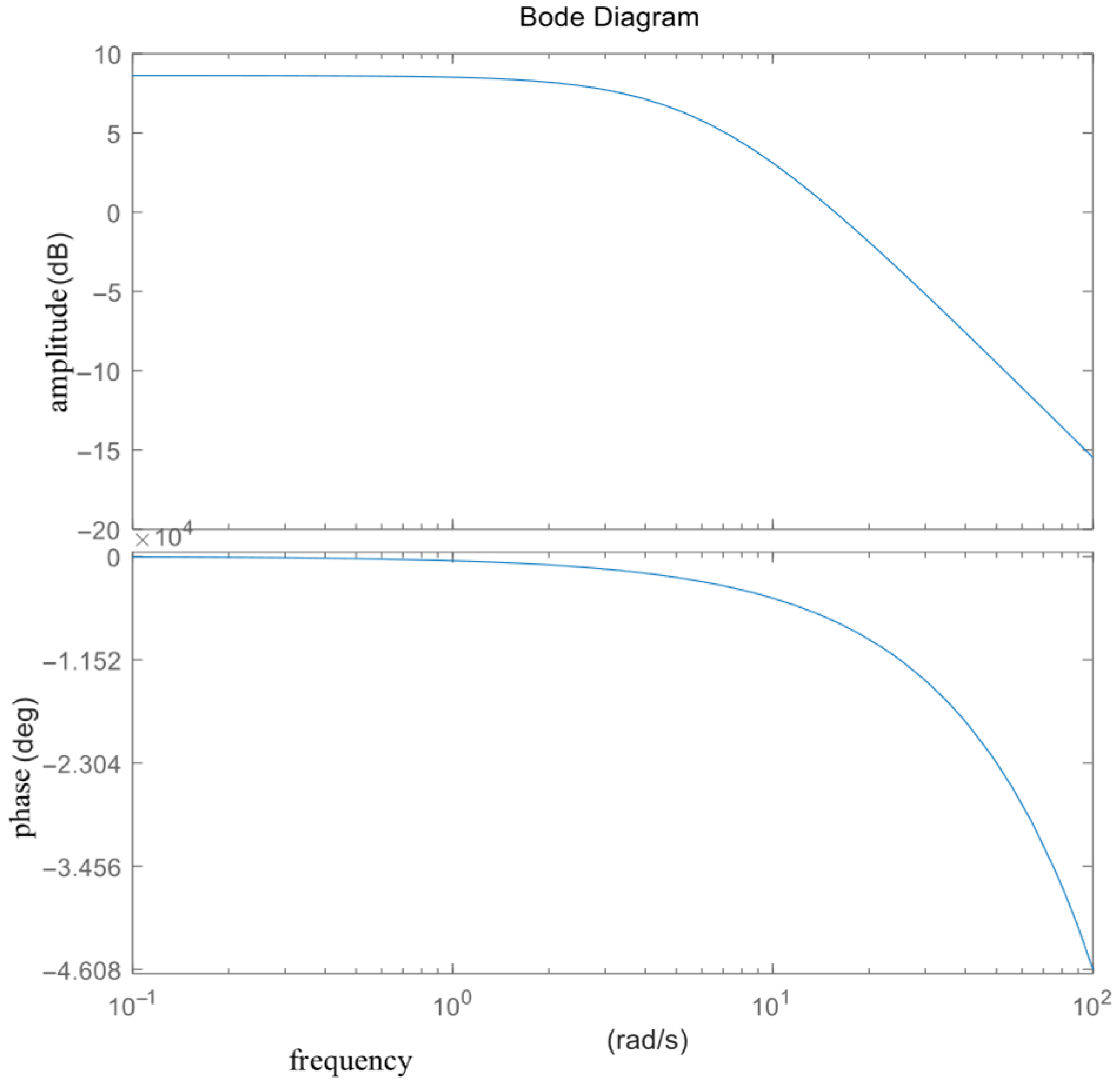
3.1. Current–Temperature Dynamics

Taking a silicon rod in the constant temperature stage as the research object [10], the heat generated by the electric heating of the silicon rod using an alternating current per unit time minus the sum of the heat absorbed during the silicon rod surface reaction per unit time and the heat dissipated by the cooling water in the reduction furnace wall and chassis jacket is equal to the change rate of the silicon rod’s stored energy.
G C d T dt = I 2 R 1 1 η K π D L ( T T A )
From this we can conclude that
G ( s ) = 2 I ( 1 η ) K π D L + G C ( 1 η ) s e τ s
τ = G C ( 1 η ) K π D L
C is the specific heat capacity of the reaction mixture in the reduction furnace, in J/(Kg·C); G is the mass of the reaction mixture in the reduction furnace, in kg; T is the surface temperature of the silicon rod, in °C; I is the heating current; R is the silicon rod’s equivalent resistance; η is the proportion of the reaction endotherm in relation to the total heat; K is the total heat transfer coefficient between the mixed gas and the surrounding medium; and L is the length of the polysilicon in the reduction furnace.
Based on the parameters derived from the transfer function in [9], we obtained the system transfer function as follows (Equation (5)):
G ( s ) = 540 32 s + 200 e 10 s
To comprehensively evaluate the system’s dynamic characteristics, frequency-domain analyses were performed on the transfer function (Equation (5)). Figure 1 presents a Bode plot, revealing a phase margin of 130.70° at the 15.90 rad/s gain crossover frequency and a gain margin of 0.11 dB at the 15.67 rad/s phase crossover frequency, indicating stable performance despite the system’s time delay. The −3 dB bandwidth at 0.25 rad/s reflects the inherent speed limitations of the system. Complementing this analysis, Figure 2 shows a Nyquist plot, in which the trajectory maintains a safe distance from the (−1, 0) point, confirming the system’s robust stability.
Since the ratio of the mixed gas composed of SiHCl3 and H2 changes during the actual production time, it can also be considered that the parameter K changes over time. The diameter of the silicon rod, D, changes from 8 mm to 150 mm at the beginning of the process, with a wide range of changes. The temperature delay time constant, τ , is related to the controlled object, the silicon rod, and the diameter of the silicon rod gradually increases over time. This parameter is generally taken to be 5~12 s.
It can be seen from this that the temperature control system is a system with a large time lag and a system whose structural parameters will change over time. If the system adopts traditional PID control, it will produce large fluctuations.

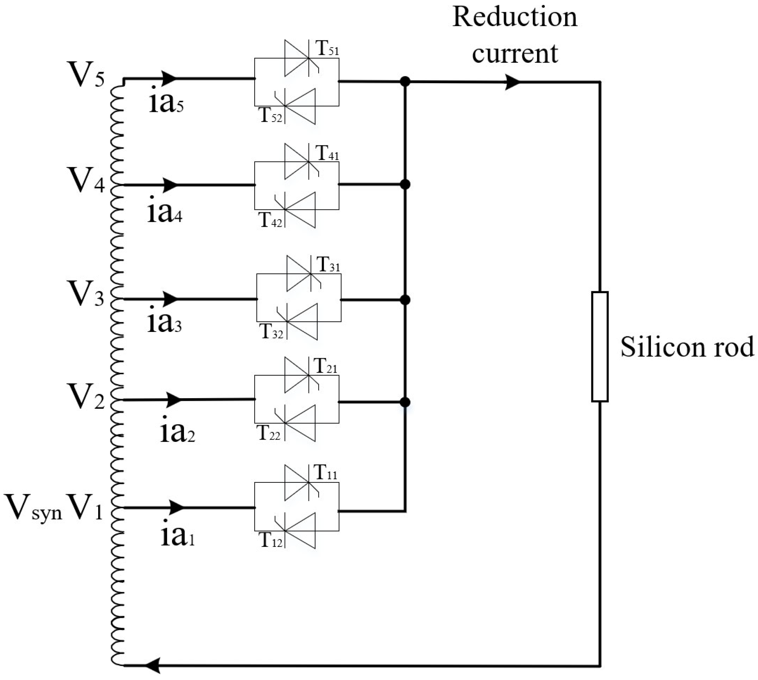
3.2. Power Amplifier
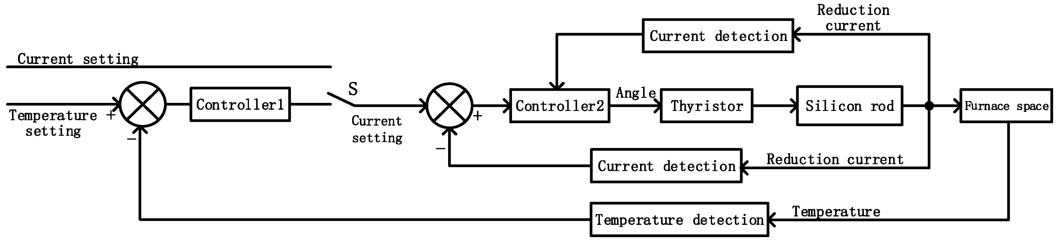
The transfer function of the thyristor power amplification link is considered a first-order lag function. Taking ABB’s high-power thyristor model 5STP03D6500 as an example, the amplification factor Ks is 1000 and the inertia time constant Ts is 5 ms.
Based on these parameters, the transfer function of the adopted thyristor model can be derived as shown in Equation (14). This first-order transfer function representation captures the essential dynamic characteristics of the thyristor power amplifier, where the 5 ms time constant reflects the device’s inherent response delay and the large amplification factor of 1000 indicates its high power gain capability. The formulation in Equation (14) provides a mathematically tractable model that is suitable for control system design and stability analysis while maintaining sufficient fidelity to represent the actual thyristor’s behavior in the polysilicon reduction furnace power system. This modeling approach is particularly valuable for developing the dual-loop control architecture discussed previously, as it enables the precise characterization of the power amplification stage’s dynamics within the overall system framework.

4. Control Strategy

In order to achieve constant temperature control and reduce the heating current fluctuations, this paper proposes dual-closed-loop control, as shown in Figure 3. The inner loop adopts voltage-limited current closed-loop hysteresis PID control, and the outer loop adopts temperature closed-loop control combining MFAC and improved PID.
Taking into account load changes, the non-ideal characteristics of thyristor action, sensor accuracy limitations, etc., the current closed loop adopts voltage-limited hysteresis PID control by combining the precise regulation of traditional PID with the robustness of hysteresis control. PID control uses proportional terms to quickly respond to current deviations, integral terms to eliminate steady-state errors, and differential terms to predict trends to reduce overshoots, while the voltage-limited hysteresis characteristic sets the hysteresis band and output limits around the target current. Especially in the face of sensor accuracy limitations, hysteresis can mask small measurement fluctuations and reduce the impact of sensor errors on the control. The logic of controller 2 is shown in Figure 4.
Select logic function: If the limit is exceeded, the trigger angle increment is zero; otherwise the incremental output is superimposed.
In view of the large time lag and changes over time in the structural parameters of the polysilicon reduction furnace temperature control system, this paper proposes a control algorithm that combines MFAC with improved PID. When the PID control method has a large forward deviation (initial stage), appropriate PID parameters can be set to increase the adjustment speed. However, when approaching the control target, there are problems such as difficulties in parameter adjustment and insufficient anti-disturbance abilities in nonlinear and time-varying systems. MFAC can compensate for system uncertainties (such as load mutations, the nonlinear characteristics of thyristors, or sensor noise) in real time without relying on an accurate mathematical model, especially for large-time-lag systems. Therefore, the two control strategies are combined. When the deviation is large, the control output of the two is summed as the output, but when the deviation is small, only the output of MFAC is output. The logic of controller 1 is as follows:
u ( k ) = u f ( k ) + u b ( k )
u ( k ) represents the controller output at time k, u f ( k ) is the output of the improved PID at time k, and u b ( k ) represents the output of MFAC at time k.
u f ( k ) = u f ( k 1 ) + Δ u f ( k )
Δ u f ( k ) K p e ( k ) e ( k 1 ) + K i e ( k ) e ( k ) / T d 0.15 0 e ( k ) / T d < 0.15
e k = T d T k
u f ( k 1 ) is the output of the improved PID at time k − 1. Δ u f ( k ) represents the increment of the output at time k; e k indicates the deviation between the given value Td at time k and the temperature feedback value at time k. Kp and Ki represent the proportional coefficient and the integral coefficient, respectively.
u b ( k ) = u b ( k 1 ) + ρ ϕ ( k ) λ + ϕ Λ ( k ) 2 [ T d ( k + 1 ) T ( k ) ]
ϕ Λ ( k ) = ϕ Λ ( k 1 ) + η u b ( k 1 ) μ + u b ( k 1 ) 2 [ Δ T ( k ) ϕ Λ ( k 1 ) Δ u b ( k 1 ) ]
ϕ Λ ( k ) = ϕ Λ ( 1 ) = 0.5          w h e n     ϕ Λ ( k ) ε     o r   Δ u b ( k 1 ) ε
Ρ is the learning factor, λ is the weight factor, η is the step sequence, and μ is the penalty factor.
The hysteresis comparator employs a symmetrical deadband of ±0.05 A (0.0125% of 400 A at the full scale), determined through multi-objective optimization that carefully balances three critical engineering considerations—the ±0.02 A noise floor of the current measurement system, the ±0.1% current stability requirement for high-quality silicon crystallization, and power electronics constraints requiring the thyristor switching frequencies to remain below 500 Hz for thermal management—with this optimal parameter configuration mathematically expressed in Equation (13) to ensure robust system performance while addressing all the practical implementation constraints.
I ref = I set + 0.05       I meas < I set 0.05 I set 0.05       I meas > I set 0.05 I s e t p r e v     o t h e r w i s e
Here, I ref is the reference current; I set is the set current; I meas is the measured current; and I s e t p r e v is the held previous output current.

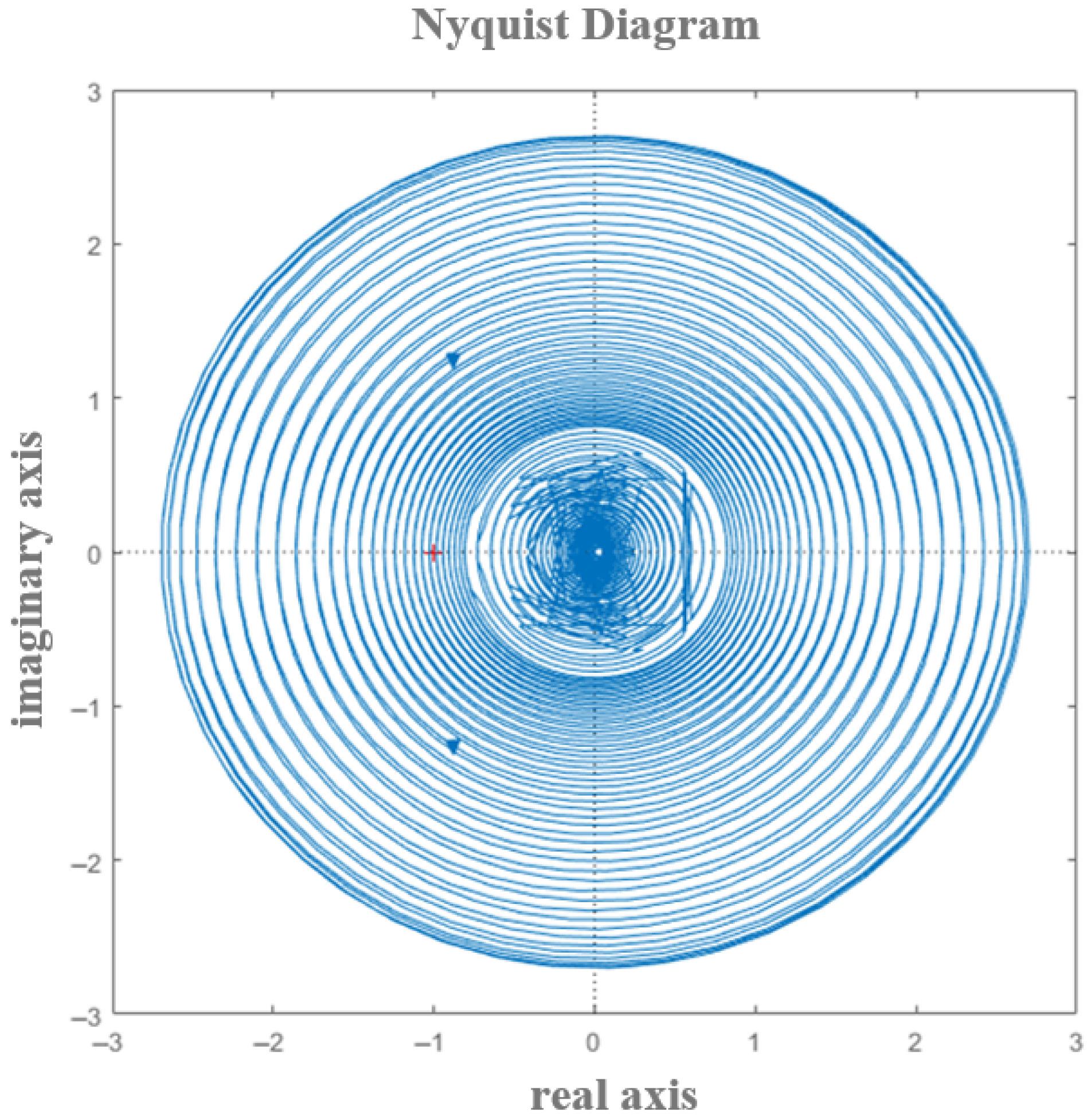
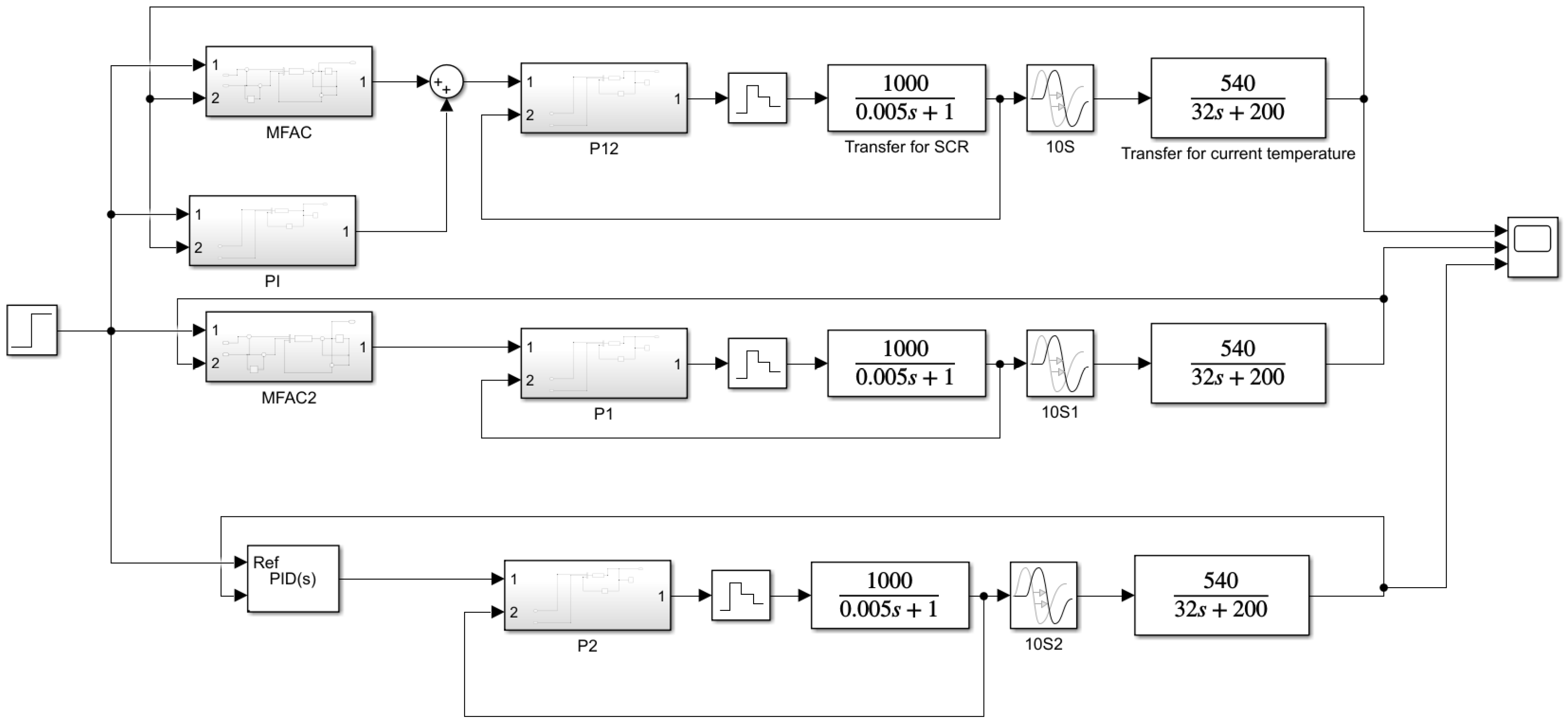
5. Theoretical Validation

Here, we describe how a PI-MFAC model was constructed based on the theoretical foundations mentioned above. As a comparison, we also needed to build an MFAC model and improve the PI model. After completing the construction of the algorithm model, it was compared to the actual model, which adopted a five-level stacked structure.

5.1. Algorithm Verification

A simulation model of the temperature control system of the polysilicon reduction furnace was built in Simulink, where the thyristor model was
1000 0.005 S + 1
Based on the actual data from a newly built system, the delay time constant τ of the current temperature transfer function was taken to be 10, and the other parts was
540 200 + 32 S
The S function P12 represents hysteresis PID control, the S function MFAC represents model-free adaptive control, and the S function PI represents improved PID control. For comparison, pure MFAC and PID control temperature outer loops were added. Figure 5 shows the simulation model of the system built according to the above description in Simulink. The specific Simulink model files are included as Supplementary Materials and can be found in the submitted files.
The given temperature was 1000 °C. When the parameters were adjusted to achieve the best controller output performance, the hysteresis PID control parameters of the current inner loop were Kp = 0.0005, Ki = 0.0001, and Kd = 0. The MFAC parameters were ρ = 0.0504, λ = 0.9, η = 1.8, and μ = 0.01, and the improved PID control parameters were Kp = 0.0005, Ki = 0.0001, and Kd = 0. For comparison, the parameters for pure MFAC were ρ = 0.0504, λ = 0.9, η = 1.8, and μ = 0.01, and the pure PID temperature outer loop control parameters were Kp = 0.0055, Ki = 0.0111, and Kd = 0. The simulation results are shown in Figure 6.
According to the simulation results in Figure 6, a comparative simulation was conducted to more intuitively demonstrate the performance of the three control methods. The key performance indicators are summarized in Table 1.
The simulation results show the PI-MFAC method achieved a 28.17 s rise time, 0.002% overshoot, and 0.002% steady-state error, outperforming pure MFAC and PID, and the results show a significant improvement in the rise time.
Indeed, reducing the rise time can significantly improve the overall dynamic response speed of the system while also shortening the system startup time. However, it is crucial to prevent excessive current fluctuations (overshoots) to avoid the risk of thermal stratification or even fracturing in the silicon rods, since the current is proportionally converted into the temperature. Thermal stratification and fractures in silicon rods can negatively impact the polysilicon quality.

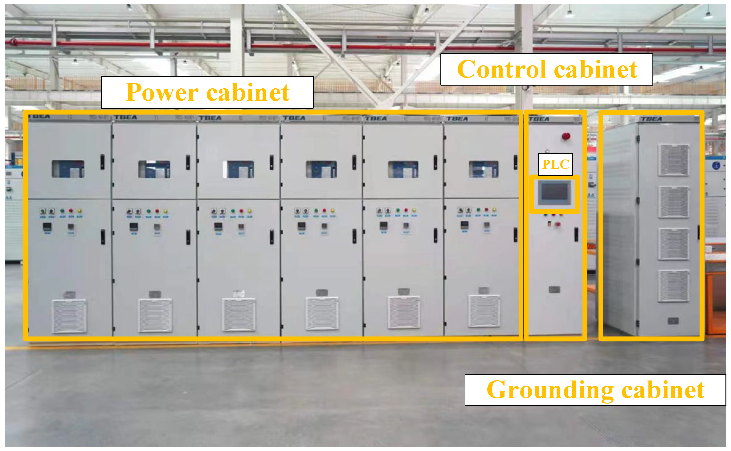
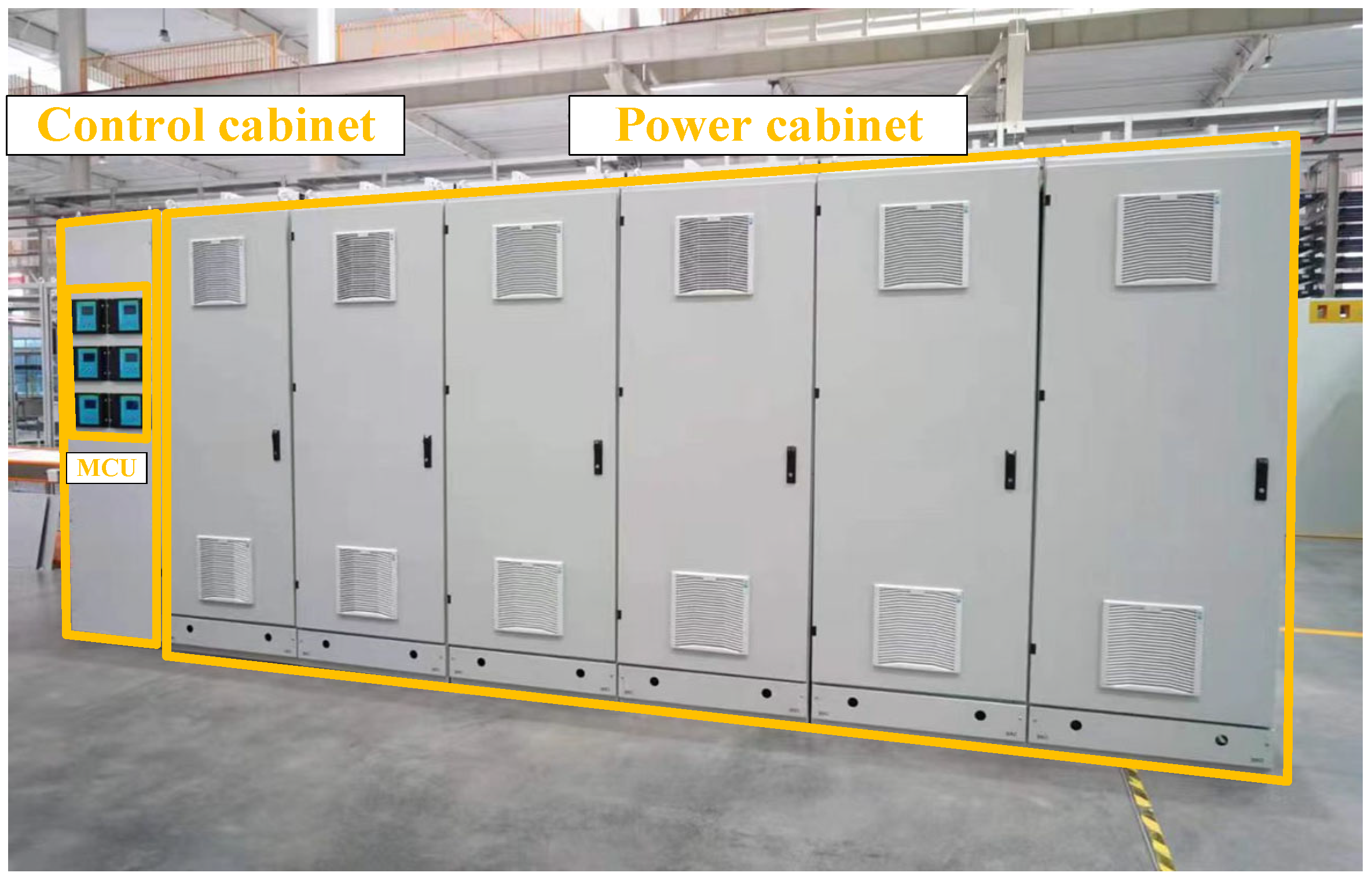
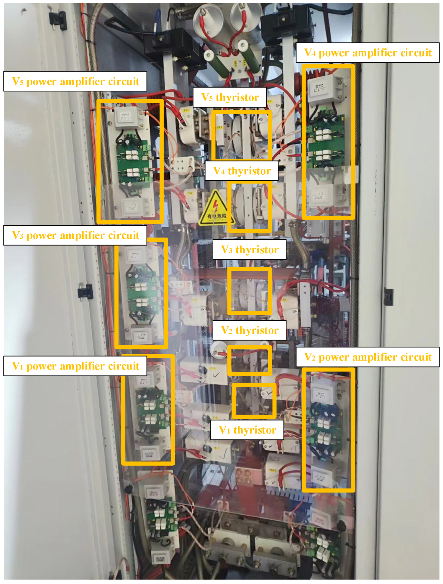
5.2. Practical Validation

We verified the effectiveness of the proposed method using actual models based on practical applications. The model we selected was the most commonly used model in the polycrystalline silicon preparation industry [5]. The simulation model was a five-level voltage stack, and the specific model is shown in Figure 7. In this model, there were five voltage levels, with the effective voltage values from high to low being 2800 V, 1550 V, 1000 V, 660 V, and 400 V, respectively. We selected 400 V as the synchronous voltage to determine the initial phase of the triggering angle for each voltage level. We simulated a silicon rod using a resistor with a resistance value of 2.8 ohms.
After zero crossing detection, the synchronous voltage became a square wave and reached the controller (Figure 8). The controller detected the rising edge to obtain the initial phase of each gear voltage. At the same time, the reduction current passed through the current conversion module and reached the controller and was sent as a feedback signal to controller 2. The receipt of this feedback signal completed the prediction model’s control of the output current, as shown in the reduction current in Figure 3 and Figure 4. In the current inner loop, the controller controlled the restoration current by reading the value of the restoration current and setting the value to determine the increase or decrease in the gear or angle. At the same time, there was only single-layer control or stacked control in the adjacent two layers. The controller normally started increasing the order of the incurrent in small steps followed by larger steps. The conduction sequence started from V1-V12-V23-V34-V45, where V1 represents that the current voltage applied to both sides of the silicon rod was only a V1-level voltage, V12 represents that the current voltage applied to both sides of the silicon rod was a stack of a V1-level voltage and V2-level voltage, and so on. In the temperature outer loop, the microcontroller obtained the surface temperature of the silicon rod by collecting data from the external temperature sensor. It then calculated the temperature conversion current by inverting the transfer function in Equation (15). The temperature conversion current was processed by controller 1 to generate the final set current.
There were five sets of output signals for the controller, where P11 and P12 represent the forward and reverse PWM waveforms at the V1 level, respectively, with the representations being similar for the other sets. After passing through the power amplification circuit, these five sets of signals were applied to the thyristors of each gear.
Figure 9 and Figure 10 show the front and rear views of the industrial model used in this experiment. The system consisted of six power cabinets, one control cabinet, and one grounding cabinet. Each power cabinet contained a complete five-stage stacked circuit (Figure 11). The control cabinet housed both a microcontroller and a PLC controller.
A trend chart of the changes in the V1 current at the beginning of the system startup is shown in Figure 12. As the program was adjusted, the trigger angle gradually decreased from 180°, causing the voltage applied to both sides of the simulated silicon rod to increase and the reduction current to gradually increase.
The following figure shows the waveforms of the set temperature and actual temperature during actual operation (Figure 13). Tset is the waveform of the set temperature and also the output waveform of the PI-MAFC model, while T is the waveform of the temperature changes on the surface of the silicon rod. It is not difficult to see that the changes in the surface temperature of the silicon rod basically followed the changes in the set temperature. The changes in the temperature on the surface of the silicon rod, shown in Figure 13, occurred in five stages, corresponding to different voltage (current) levels, namely V1-V12-V23-V34-V45. We selected two real-time current waveforms for each temperature stage, corresponding to (a), (b), (c), (d), and (e) in Figure 13.
The experimental validation demonstrated the excellent control performance of the proposed system. The obtained temperature curve showed remarkable consistency with the set temperature profile, with the actual temperature reaching the target in 28.18 s. The system exhibited a minimal overshoot (0.23%) and maintained high precision, with a maximum steady-state error of just 0.26%. Furthermore, the maximum observed time discrepancy between the setpoint and actual temperature was limited to 3.12 s. The 3.12 s maximum time lag represents an excellent performance characteristic for this thermal system, considering the inherent inertia of the polysilicon reduction process. This small temporal discrepancy demonstrates that our control system maintained tight synchronization between the set and actual thermal profiles while effectively compensating for various process disturbances. These results confirm that the developed control system fully satisfies all the specified technical requirements for this polysilicon reduction furnace application.

6. Conclusions

The dual-loop control system proposed in this paper combines model-free adaptive control (MFAC) with an improved PID controller, effectively addressing the challenges of temperature control in the power system of polysilicon reduction furnaces. The inner lag PID current loop ensures rapid and stable current regulation, while the outer hybrid MFAC-PID temperature loop enhances the tracking performance and compensates for the system’s nonlinearity and time-varying delays. The simulation and experimental results demonstrate the effectiveness of this approach, which achieved a fast rise time (28.17 s), minimal overshoot (0.002%), and low steady-state error (0.002%), significantly outperforming both MFAC and PID control alone.
The universality of this method is reflected in its adaptability to systems with uncertain dynamics and time-varying parameters, making it applicable to industrial processes other than polysilicon production. The MFAC component eliminates the reliance on precise system modeling, while the improved PID controller ensures robustness against disturbances. In addition, this control strategy has huge application potential in other time-delay systems, such as chemical reactors, heat treatment units, and energy conversion systems, which usually have significant time delays and parameter variations.
Beyond its immediate application in polysilicon production, the developed methodology establishes a new framework for complex thermal process control that bridges the gap between advanced control theory and industrial requirements. The system’s modular architecture and demonstrated performance in diverse applications suggest strong potential for extension to other challenging industrial domains, including semiconductor crystal growth, metallurgical processing, and distributed energy systems. Future research directions will focus on expanding the controller’s capabilities to multi-variable scenarios and optimizing its implementation on emerging smart manufacturing platforms, while maintaining the proven robustness and adaptability that characterize the current design.

Supplementary Materials

The following supporting information can be downloaded at: https://www.mdpi.com/article/10.3390/en18143707/s1, Supplementary File S1: “beforeandback2.m”: This file contains the MFAC running code. Supplementary File S2: “s_pid_control_d.m”: This file contains the hysteresis PID control code. Supplementary File S3: “s_pid_control_d3.m”: This file contains the improved PID control code. Supplementary File S4: “system_model.slx”: This file represents the Simulink model of the entire simulation system.

Author Contributions

All the authors contributed to the study’s conception and design. The research design, data analysis, and manuscript writing were performed by S.L. and Z.Y. Theoretical support was provided and data interpretation and discussion were participated in by Z.Y., S.J., T.Z. and G.C. Experimental data collection and the simulation setup were performed by Z.Y., Z.C. and G.L. The first draft of the manuscript was written by S.L., and all the authors commented on previous versions of the manuscript. All authors have read and agreed to the published version of the manuscript.

Funding

This research was funded by the 2024 Hunan Provincial Natural Science Foundation Program (grant number 2024JJ7438), the Excellent Youth Program of the Education Department of Hunan Province (grant number 23B0404), and the Central Government’s Guiding Local Science and Technology Development Program (grant number 2024ZYC026). We acknowledge that financial gains or losses may result from the publication of this manuscript.

Data Availability Statement

All the data were obtained through experimental simulations, and the simulation procedures and results are described in detail within this study. The complete dataset is available upon request from the corresponding author.

Conflicts of Interest

All the authors declare that they have no commercial conflicts of interest related to this study. The research funding was provided by the 2024 Hunan Provincial Natural Science Foundation Program, and no commercial companies or financial interests influenced the results of the study.

References

  1. Luo, X.; Huang, L.; Xu, Y.; Wang, Q. Optimization of Energy Saving and Consumption Reduction of Polysilicon Siemens Method Based on Improved K-means Algorithm. Teh. Vjesn. 2025, 32, 132–141. [Google Scholar]
  2. del Coso, G.; Obías, I.; Cañizo, C.; Luque, A. Temperature homogeneity of polysilicon rods in a Siemens reactor. J. Cryst. Growth 2007, 299, 165–170. [Google Scholar] [CrossRef]
  3. Si, W.; Wang, N.; Zong, Y.; Dai, G.; Zhao, L.; Xin, Z.; Jiang, G. Investigation of heat transfer mechanism affecting temperature homogeneity at polysilicon rods in a Siemens reduction furnace. J. Cryst. Growth 2024, 636, 127693. [Google Scholar] [CrossRef]
  4. Ma, Y. Simulation of Temperature Field in Polysilicon Reduction Furnace. Master’s Thesis, China University of Mining and Technology, Xuzhou, China, 16 August 2019. [Google Scholar]
  5. Li, W. Research and Design of 60-Pair Rod Polysilicon Reduction Electrical System. Master’s Thesis, Xi’an University of Technology, Xi’an, China, 2016. [Google Scholar]
  6. Ren, J.; Liu, D.; Wan, Y.; Shi, S.; Liu, Y. Iterative ESO-Based Data-Driven Active Disturbance Rejection Learning Control of Czochralski Silicon Single Crystal Growth Process. In Proceedings of the 2024 American Control Conference (ACC), Toronto, ON, Canada, 10–12 July 2024. [Google Scholar]
  7. Wan, Y.; Liu, D.; Ren, J.-C. Iterative learning-based predictive control method for electronic grade silicon single crystal batch process. IEEE Trans. Semicond. Manuf. 2023, 36, 239–250. [Google Scholar] [CrossRef]
  8. Cheng, J. Research on control method of polysilicon growth rate in reduction furnace. Sichuan Chem. Ind. 2022, 25, 34–36+44. [Google Scholar]
  9. Zou, G. Model-Free Adaptive Fuzzy Control for Silicon Rod Temperature In polysilicon Reduction Furnace. Master’s Thesis, Hunan University, Changsha, China, 15 April 2013. [Google Scholar]
  10. Ovcharenko, V.; Olena, T. Extreme Step-Type Automatic Temperature Control System For High-Temperature Heater From CCCM. In Proceedings of the 19th International Scientific and Practical Conference Creative Business Management and Implementation of New Ideas, Tallinn, Estonia, 14–17 May 2024; p. 281. [Google Scholar]
Figure 1. Bode diagram.
Energies 18 03707 g001
Figure 2. Nyquist diagram.
Energies 18 03707 g002
Figure 3. The control system for the constant-temperature stage of polysilicon production.
Energies 18 03707 g003
Figure 4. Current control using hysteresis PID.
Energies 18 03707 g004
Figure 5. System simulation diagram.
Energies 18 03707 g005
Figure 6. Simulation output comparison chart.
Energies 18 03707 g006
Figure 7. Polycrystalline silicon power supply model.
Energies 18 03707 g007
Figure 8. System control block diagram.
Energies 18 03707 g008
Figure 9. Front of polycrystalline silicon reduction furnace device.
Energies 18 03707 g009
Figure 10. Rear of polycrystalline silicon reduction furnace device.
Energies 18 03707 g010
Figure 11. Internal structure of power cabinet.
Energies 18 03707 g011
Figure 12. Current increase waveform for V1 gear.
Energies 18 03707 g012
Figure 13. Comparison chart of changes in set value and operating value of silicon rod current.
Energies 18 03707 g013
Table 1. Comparison of key performance indicators of three methods.
Control MethodRise Time (s)Overshoot (%)Steady-State Error (%)
PI-MFAC28.170.0020.002
PID50.490.00120.0012
MFAC112.7100.012
Disclaimer/Publisher’s Note: The statements, opinions and data contained in all publications are solely those of the individual author(s) and contributor(s) and not of MDPI and/or the editor(s). MDPI and/or the editor(s) disclaim responsibility for any injury to people or property resulting from any ideas, methods, instructions or products referred to in the content.

