Article

The Optimization of Mechanical Phase-Shifting Transformer Tap Positions Based on an Open-Loop and Closed-Loop Hybrid Strategy

1
State Grid Jiangsu Electric Power Co., Ltd., Research Institute, Nanjing 211103, China
2
School of Electrical and Power Engineering, Hohai University, Nanjing 211100, China
*
Author to whom correspondence should be addressed.
Energies 2025, 18(14), 3699; https://doi.org/10.3390/en18143699
Submission received: 12 May 2025 / Revised: 27 May 2025 / Accepted: 29 May 2025 / Published: 14 July 2025

Abstract

Phase-shifting transformers play a crucial role in power grid stability and efficiency. They adjust phase differences between loads, improve transmission efficiency, and balance loads during large-scale power transmission and grid integration. However, traditional mechanical phase-shifting transformers use fixed-tap designs with limited taps, preventing continuous and precise adjustments. This discrete adjustment method affects control accuracy and optimal tap position selection for proper power flow. This paper proposes a hybrid open-loop and closed-loop control strategy. This strategy maintains the phase-shifting transformer at its optimal tap position, enhancing system regulation precision and control effectiveness.

1. Introduction

In recent years, with the rapid growth of China’s economy and the continuous development of power system infrastructure, the structure and operation mode of the power grid are increasingly complex [1]. How to ensure the safe, reliable, and economical operation of the power grid is a challenge. Rational distribution of system power flow offers a solution. However, power flow in traditional power grids is affected by power supply and load distribution. This creates natural distribution characteristics, leading to frequent light-load and heavy-load conditions on transmission lines. Light-load conditions result in low resource utilization efficiency, compromising economic grid operation. Conversely, heavy-load conditions cause line overload, limiting the power supply capacity of the grid [2,3,4,5]. Therefore, developing effective power flow control technology is crucial. It enables controllable power flow, ensures balanced line load, and improves overall grid economic efficiency. With the continuous progress of power electronics technology, complex power flow control technologies, such as unified power flow controllers (UPFCs) [6,7,8], static synchronous series compensators (SSSCs) [9], and phase-shifting transformer (PSTs) [10,11,12,13,14], have received considerable attention and show broad potential.
As one of the key pieces of equipment for phase adjustment and the optimization of power transmission, the PST plays a key role in the electrical system [15]. The existing research has carried out correlation analysis on the mechanism of the PST, built the correlation model of the PST, and deepened the understanding of the working effect of the PST. For example, reference [16] has analyzed the relationship between the trigger angle and the phase shift in the discrete regulated PST controlled by a thyristor, and established a nonlinear mathematical model, which provides a theoretical basis for accurate control. In the system application, an optimal power flow model including a phase-shifting transformer is proposed, which shows that optimizing the phase-shifting angle can effectively reduce the system loss and improve the distribution [17]. In addition to changing the power flow distribution, the PST is also used to deal with the abnormal state of some lines, and the control strategies for different objectives have also been widely studied. For example, to effectively suppress the fault current, the excitation impedance switch control strategy of the PST is systematically studied in reference [18], and an adaptive control algorithm is proposed. The introduction of a unified polyphase modulation control strategy solves the problem of current spikes during load transients and significantly improves the quality of current waveforms [19]. The control strategy of the PST, considering the influence of the PST on power line distribution, system loss, and node voltage, guides actual operation control [20]; Reference [21] discussed the key problems of the PST in closed-loop application, and also designed a multi-objective optimal regulation strategy. The PST technology has also been fully developed. For example, [22] proposed a new concept of an independent fast PST (IFST), which has significant advantages in response speed and control accuracy compared with the traditional PST.
One study has compared the performance characteristics of different types of PSTs, revealing the differences between mechanical regulation and electronic control types in multiple dimensions [23]. Although the electronically controlled PST has the advantages of a fast response speed and unlimited adjustability, the mechanical phase-shifting transformer (MPST) with an on-load tap position converter is very advantageous due to its low operational costs and high reliability [24]. They are simple in structure design, relatively low in cost, stable in performance, easy to maintain and debug, and are increasingly used in power systems, making them indispensable technologies for power flow control and grid operation optimization [25,26,27,28,29]. Compared to power electronic devices, mechanical phase-shifting transformers offer significant advantages in operating costs and reliability. Their initial investment costs are lower, providing a clear economic benefit for projects with limited budgets. Additionally, the mechanical phase-shifting transformer features a simple structural design with fewer points of failure, making maintenance and commissioning more convenient, and the technical barrier is lower. Spare part supply is guaranteed, and maintenance costs are manageable. Despite these advantages, the MPST still faces some limitations, mainly due to its relatively slow dynamic response. This is because they rely on physical mechanical motion to adjust the phase angle [30,31]. When the output power needs to be adjusted quickly to closely match the reference power, the MPST may not respond quickly enough, resulting in deviation from the required output power. The existing research mainly focuses on the electrical PST, but the control method of the MPST is not considered enough. Therefore, it is of great significance to study the control method of the MPST. This paper focuses on the design and analysis of control circuits for MPST, aiming to address the limitations of their response time and optimize their performance. The primary contributions of this work are as follows:
(1)
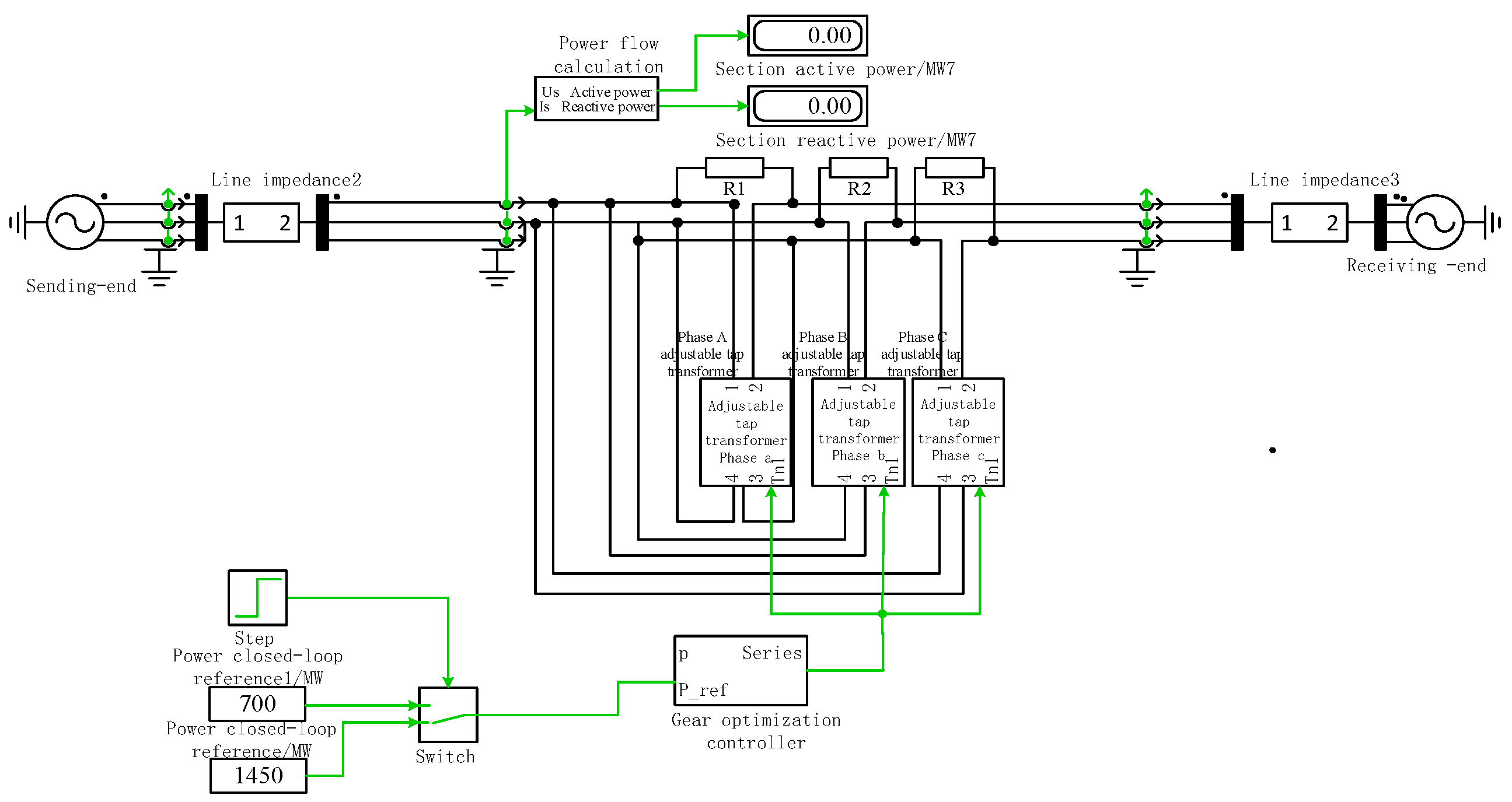
A novel control circuit for MPST is proposed, which is based on a hybrid control strategy that combines both open-loop and closed-loop control modes. By integrating a tap position optimization controller and a line power flow calculator, the control circuit achieves precise adjustment and optimization of the transformer’s tap. The system dynamically switches between open-loop and closed-loop control modes, effectively mitigating issues of system oscillation while enhancing control accuracy and improving response speed.
(2)
Based on the newly proposed control framework, a hybrid open-closed loop strategy is developed that integrates the continuous control function of a PI regulator with the discrete step adjustment of a mechanical tap changer. This strategy enables the real-time fine-tuning and optimization of the tap position in PSTs. When the system reaches a steady operational state or achieves the desired control objectives, it seamlessly transitions to pure mechanical tap changer control. This ensures a smooth handover from continuous to discrete regulation, allowing the system to maintain the optimized tap setting under stable conditions and guaranteeing long-term operational stability and performance.

2. Limitations and Impacts of Mechanical Phase-Shifting Transformer in Power Flow Control

2.1. The Principle of Phase-Shifting Transformer Suppression of System Oscillations

The PST is a widely used power flow control device both domestically and internationally, which controls the power flow by adjusting the phase angle at both ends of the transmission line. The PST consists of a series transformer, a parallel transformer, and a conversion device [32]. The phase-shifter first obtains the line voltage, then, through the conversion device, generates the compensation voltage that is inserted into the line, thereby changing the line power. Figure 1 shows the equivalent diagram of the PST after being integrated into the system.
Figure 2 is a typical topology diagram of a mechanical phase shifter, showing a three-phase configuration where each phase incorporates both series-connected and parallel-connected transformer arrangements. Each phase input passes through a series transformer for voltage regulation and impedance matching, then connects to a parallel transformer system that enables phase angle adjustment through controlled magnetic coupling, before reaching the respective output terminals.
XL is the equivalent impedance of the transmission line;
S and R represent the sending and receiving ends of the line, respectively;
L is the terminal node of the PST;
US, UR, ZS, and ZR represent the voltage magnitudes and impedance values at the sending and receiving ends, respectively.
The active power transmitted through the line can be expressed as below:
P = U S U R X sin ( δ ± σ )
δ is the voltage phase angle difference between the sending end and the receiving end;
σ is the phase angle difference between UL and US after phase-shifting by the PST.
As can be seen, changes in σ can significantly impact the active power of the line. By adjusting the tap changer of the voltage-regulating PST to inject a voltage ΔU into the line and change the voltage phase angles on both sides of the device, the power flow can be controlled.
The tap adjustment of the voltage-regulating PST is an important aspect of research on PSTs. In the equivalent model of the voltage-regulating PST shown in Figure 1, the active power transmitted through the transmission line can also be expressed as follows:
P = I L U L = U R U S + Δ U Z U L
During the tap position adjustment process, the transmission line current IL changes, thereby affecting the line power. The factors influencing the transmission line current IL are the output voltage ΔU of the voltage-regulating PST and the system’s total impedance, which can be expressed as follows:
I L = Δ U Z s + Z L + Z R
Assuming that the receiving end voltage UR, impedance ZR, and sending end voltage US remain constant, when there is a change in the external power grid (such as a line N-1 fault), and the line current (i.e., power) changes to k times its original value, the expression is as follows:
I L I L = Δ U Z S + Z L + Z R Δ U Z S + Z L + Z R = k
Simplifying this, we obtain the following:
Z S = Z S + ( 1 k ) ( Z L + Z R ) k
When k = 1.5, the equation becomes the following:
Z S = Z S 0.5 ( Z L + Z R ) 2 = 1 2 Z S 1 4 ( Z L + Z R )
When k = 2, the equation becomes the following:
Z S = Z S ( Z L + Z R ) 2 = 1 2 Z S 1 2 ( Z L + Z R )
When k = 0.5, the equation becomes the following:
Z S = Z S + 0.5 ( Z L + Z R ) 0.5 = 2 Z S + Z L + Z R
It can be seen that under different tap position adjustments, the total impedance of the voltage-regulating PST changes significantly. When the operating conditions of the external power grid change, causing the sending-end source impedance to change to Z S + ( 1 k ) ( Z L + Z R ) k times its original value, the change in line power due to a one-tap position adjustment of the PST will become k times the original value. The power change for each tap position adjustment of the PST is proportional to the product of the sending end and receiving end voltages, USUR. When the sending and receiving end voltages are changed to k1 and k2 times their original values, respectively, the power change for each tap position adjustment of the PST will change to k1k2 times the original value.

2.2. The Limitations of a Mechanical Phase-Shifting Transformer

Based on the analysis in Section 2.1, the adjustment of the phase-shifter tap position plays a crucial role in the power variations in the power system. Traditional MPST typically employ a fixed tap position design, where the number of taps is limited and non-adjustable, preventing continuous and fine-tuned regulation. This discrete adjustment method directly results in insufficient control precision, causing the system to fail to meet the precise power flow distribution requirements of the electrical network in practical applications. The inability to make fine adjustments means that the power system may not operate in an optimal state, leading to reduced power transmission efficiency. Specifically, the precise allocation of power flow is constrained, making it difficult to respond to load fluctuations and the need for system optimization.
Furthermore, as system load or generation fluctuates, traditional discrete tap position designs cannot achieve flexible, rapid, and precise phase angle adjustments, making it difficult to adjust power flow distribution promptly. In such cases, the system may fail to respond quickly to dynamic load changes, resulting in imbalanced power flow distribution. When system load increases or generation decreases, traditional MPST cannot make precise phase angle adjustments within a short time, leading to reduced power distribution efficiency. This delay in adjustment may not only affect the stability of the system but also potentially cause power flow fluctuations during dynamic processes, compromising the stability and reliability of the power supply. In extreme cases, it could even pose a risk of grid instability, impacting the safe operation of the power system.
Additionally, in the face of specific operating conditions, such as large-scale load jumps or abnormal generation fluctuations, the discrete adjustment mode of traditional phase-shifters fails to respond promptly, thus missing the optimal adjustment window. Although this delay effect may not immediately cause significant faults in the short term, the cumulative adjustment errors over time could drastically reduce system efficiency, increase energy consumption, and accelerate equipment wear, ultimately shortening the system’s operational lifespan. To mitigate these issues, there is an urgent need to adopt more refined and continuous adjustment technologies, such as electronic or digital-controlled phase-shifters, to improve the system’s adjustment response speed and precision, ensuring optimal power flow distribution and stable operation under various operating conditions.

3. Tap Position Optimization Strategy

3.1. Closed-Loop Control Strategy

Section 2.2 delves into the issue of MPSTs’ inability to select the optimal power flow and proposes a potential solution: optimizing tap position selection through a closed-loop control system combined with a feedback mechanism to address this limitation. The closed-loop control system monitors the power flow state in real time through sensors and compares it with preset target values. When the system detects a change in the power flow state, it quickly analyzes the difference between the measured and target values. Based on the feedback signal, the closed-loop control algorithm automatically selects the tap position that is closest to the target value, thereby effectively reducing adjustment errors. This method enables the system to dynamically adjust the tap position strategy according to changes in the power flow, improving the system’s adaptability to complex operating conditions.
Although closed-loop control systems theoretically provide precise regulation, their performance is still subject to certain limitations. First, closed-loop control relies on the real-time acquisition and processing of feedback signals, and the transmission and computation of these signals typically involve some time delay. Due to this delay, the system may not respond instantly, resulting in a delayed adjustment effect, which may manifest as overshooting or underadjustment. When the system response is delayed, the output signal may fluctuate significantly around the target value, ultimately causing oscillation and negatively impacting system stability. This delay effect is particularly pronounced when there are rapid load changes or sudden fluctuations in the system state, making it difficult for the system to quickly adjust to an optimal state, thereby decreasing the efficiency of the power system.
As illustrated in Figure 3, traditional closed-loop control exhibits significant limitations when responding to substantial changes in reference power. The upper panel depicts tap position variations (purple) over time, revealing initial stability at position 5 followed by rapid oscillations between positions 2 and 3 after the reference power undergoes a sharp downward adjustment at t = 10 s. Despite the control system’s initial responsive adjustment from level 5 to level 3, it fails to achieve the anticipated stable state. The lower panel displays the power flow response (red) in comparison to the reference power setpoint (green), demonstrating pronounced oscillations that persistently fluctuate around the target value without convergence after the step change from 2250 MW to 1750 MW.
This oscillatory behavior exemplifies a fundamental deficiency in traditional closed-loop control systems when managing large-scale reference power transitions. The inherent processing delay in feedback signal acquisition and analysis prevents the controller from responding with sufficient accuracy and timeliness. Consequently, the system experiences alternating cycles of control overcompensation and undercompensation, making convergence to a stable operating state unattainable. The continuous switching between tap positions and resultant power fluctuations not only diminishes operational efficiency but also potentially threatens system stability. This phenomenon underscores the imperative for implementing more sophisticated control methodologies, such as the hybrid strategy proposed in this study, in the design of PST control systems for enhanced performance and reliability.

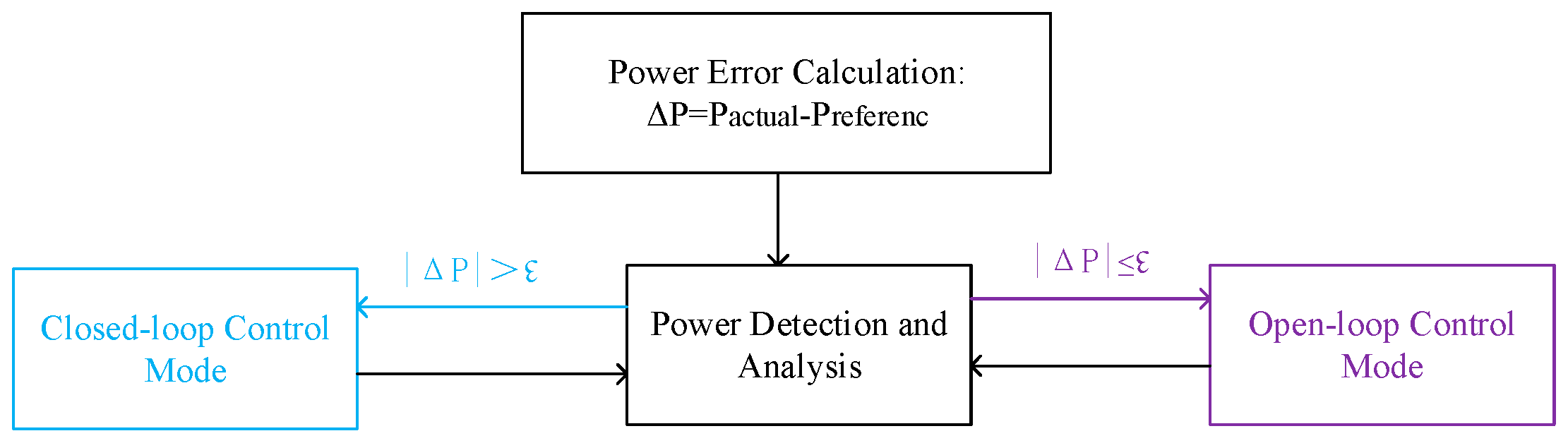
3.2. Open-Loop and Closed-Loop Hybrid Strategy

Due to the potential for system oscillations when relying solely on closed-loop control, a hybrid open-loop and closed-loop strategy is adopted. The open-loop and closed-loop hybrid strategy is not a simple concatenation of existing technologies, but rather achieves complementary advantages of two control methods through structured fusion. This control method implements intelligent mode switching based on error adaptation. It uses closed-loop control for large error situations to achieve rapid convergence. When errors fall within acceptable ranges, it switches to open-loop control to reduce computational burden. The system decides the control mode based on the following conditions:
When |Pactual − Preference| > ↋, Using closed-loop control;
When |Pactual − Preference| ≤ ↋, Using open-loop control;
Among them, ↋ represents the error tolerance preset by the system, which is usually set at 1–2% of the rated power.
As shown in Figure 4, the control system block diagram demonstrates the collaborative working mechanism of open-loop and closed-loop control, with the blue section representing the closed-loop control path and the purple section representing the open-loop control path, where the error calculation module compares the reference power with the actual power in real-time, triggering the appropriate control mode accordingly. This creates a progressive fusion rather than a simple hard switch, fully exploiting the stability advantages of open-loop and the precision of closed-loop control, thus resolving the inherent deficiencies of single control methods.
Figure 5 shows the complete process of finding the optimal tap position. First, the difference between the reference power and the actual power is calculated, determining whether the system operates in open-loop or closed-loop mode. During the closed-loop control phase, the PI controller is used to eliminate the error. The PI controller, which is the core of closed-loop control, includes both proportional and integral control components. The proportional control component of the PI controller provides a real-time, proportional response to the system’s error signal. It is sensitive enough to detect even the smallest deviation between the actual system state and the target state, and immediately initiates the appropriate adjustment mechanism. When a deviation is detected, the proportional control generates an adjustment signal proportional to the size of the error, thereby quickly reducing the deviation and improving the system’s response speed and stability. When a deviation occurs, proportional control quickly intervenes and applies the necessary adjustments to minimize the error.
The integral control component of the PI controller continuously accumulates the deviation between the actual output and the reference value, addressing these deviations to eliminate the system’s steady-state error. The continuous output signal from the PI controller is then converted to a discrete signal using the Z-transform, which steps the output and smooths the control process to reduce oscillations caused by sudden signal changes. After eliminating steady-state errors and stepping the output signal, the discrete signal is input into a Zero-Order Hold (ZOH). The ZOH retains the output signal value constant throughout each sampling cycle, ensuring signal stability in the discrete time domain and providing a stable input for subsequent numerical processing.
To prevent the system’s output from exceeding safety limits or physical constraints, maximum and minimum output limits are set. The magnitude limiter is configured based on the actual number of secondary taps of the MPST’s parallel transformer. Each phase of the MPST contains nine secondary taps, and it can output both positive and negative voltage polarities. Therefore, the maximum and minimum limits set by the magnitude limiter are 9 and −9, respectively. If the output of the ZOH’s discrete tap position signal falls below −9, the magnitude limiter forces the output tap position signal to −9. Similarly, if the output of the ZOH’s discrete tap position signal exceeds 9, the magnitude limiter forces the output tap position signal to 9. This effectively prevents any damage that could result from the system’s output exceeding the specified limits.
When switching to open-loop control, the discrete nature of the control system causes the power under closed-loop control to exhibit an opposite trend, indicating that the closed-loop control has been completed and the actual power is close to the reference power value. At this point, the system switches to open-loop mode. During the open-loop control phase, the error from the PI controller in closed-loop control is first cleared, eliminating any accumulated error from the closed-loop process and providing a zero-bias starting point for the open-loop control phase. At the same time, the output tap position is saved as a reference for subsequent optimal tap position search.
Next, the system enters the tap position optimization process. The reference tap position value is not necessarily the optimal tap position. To find the optimal tap position closer to the reference power, a trial-and-error approach is used. The tap position value is incremented or decremented from the reference tap position, and the difference between the actual power and the reference power is recorded for each adjustment. These differences reflect the deviation between the actual power and the reference power for each tap position, as detailed below:
(1)
Keep the reference tap position unchanged and record the difference between the actual power and the reference power, denoted as difference 1.
(2)
Adjust the tap position downward by one position from the reference tap position, i.e., reference tap position − 1, and maintain this for two seconds. Record the difference between the actual power and the reference power, denoted as difference 2.
(3)
Adjust the tap position upward by one position from the reference tap position, i.e., reference tap position + 1, and maintain this for two seconds. Record the difference between the actual power and the reference power, denoted as difference 3.
Finally, compare the obtained differences (difference 1, difference 2, and difference 3) and select the tap position corresponding to the smallest difference as the optimal tap position. Mathematically, the optimal tap position is determined as follows:
Optimal   Tap   Position = arg min | P a c t u a l ( i ) P r e f e r e n c e |
The main limitations are that the power control is discrete and the actual power of the line has upper and lower limits. Specific limitations are as follows:
P a c t u a l ( i ) = U S U R X sin ( δ ± σ ) σ = 2 arctan 3 n B n T n B = 9 / i n T = 2 i = 9 , 8 , 7 , , 9
i represents all possible tap positions;
nT represents the transformation ratio of the series transformer;
nB represents the transformation ratio of the parallel transformer;
Pactual(i) represents the actual power generated at tap position i;
Preference represents the reference power value;
argmin represents the value of “i” that minimizes the expression following it.
Once the optimal tap position is determined, the tap position optimization controller will operate based on this optimal tap position, thereby ensuring the optimal operation of the MPST. The two-second maintenance period was selected based on the typical mechanical operation time of 0.5–1 s for MPSTs, providing a sufficient observation window for the system to complete adjustments and observe its steady-state characteristics.
Our hybrid open-loop and closed-loop control strategy represents a fundamental departure from conventional advanced control methodologies for MPST. Unlike predictive control approaches that necessitate sophisticated forecasting algorithms and considerable computational overhead, our methodology eliminates prediction requirements, instead responding directly to system conditions by leveraging real-time voltage phase differentials between converter stations. This approach proves particularly advantageous within China’s distribution network infrastructure, where grid operators already provide prediction-based dispatch instructions, rendering additional predictive layers both redundant and potentially contradictory. Our approach distinguishes itself from purely feedback-driven optimization techniques by delivering superior performance while maintaining operational elegance. The central innovation resides in our novel solution to the inherent discrete–continuous control dilemma inherent to MPST—specifically, the integration of a 0.5-level winding to the parallel transformer, coupled with a continuously adjustable IGBT-thyristor hybrid valve array. This direct methodology achieves optimal efficiency by minimizing requisite tap adjustments when targeting specific power values. Moreover, our hybrid strategy exhibits exceptional resilience against exogenous disturbances, a critical attribute for practical grid operations. Through the development of a control architecture that appropriately processes real-time voltage phase information, we have engineered a remarkably stable, streamlined, and dependable control solution. This architectural simplicity translates directly to reduced implementation complexity and maintenance requirements, yielding substantial practical advantages in field deployment scenarios.

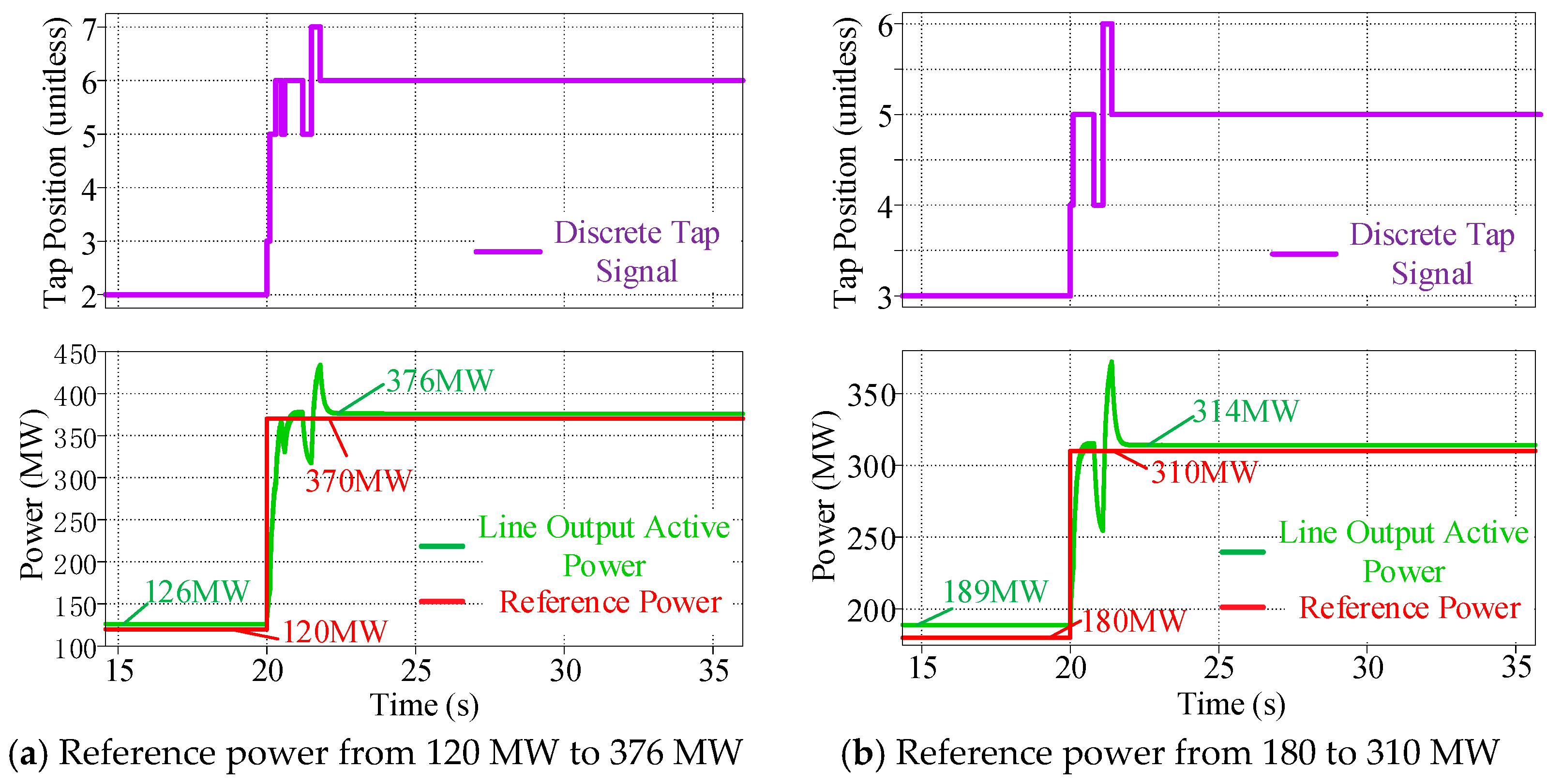
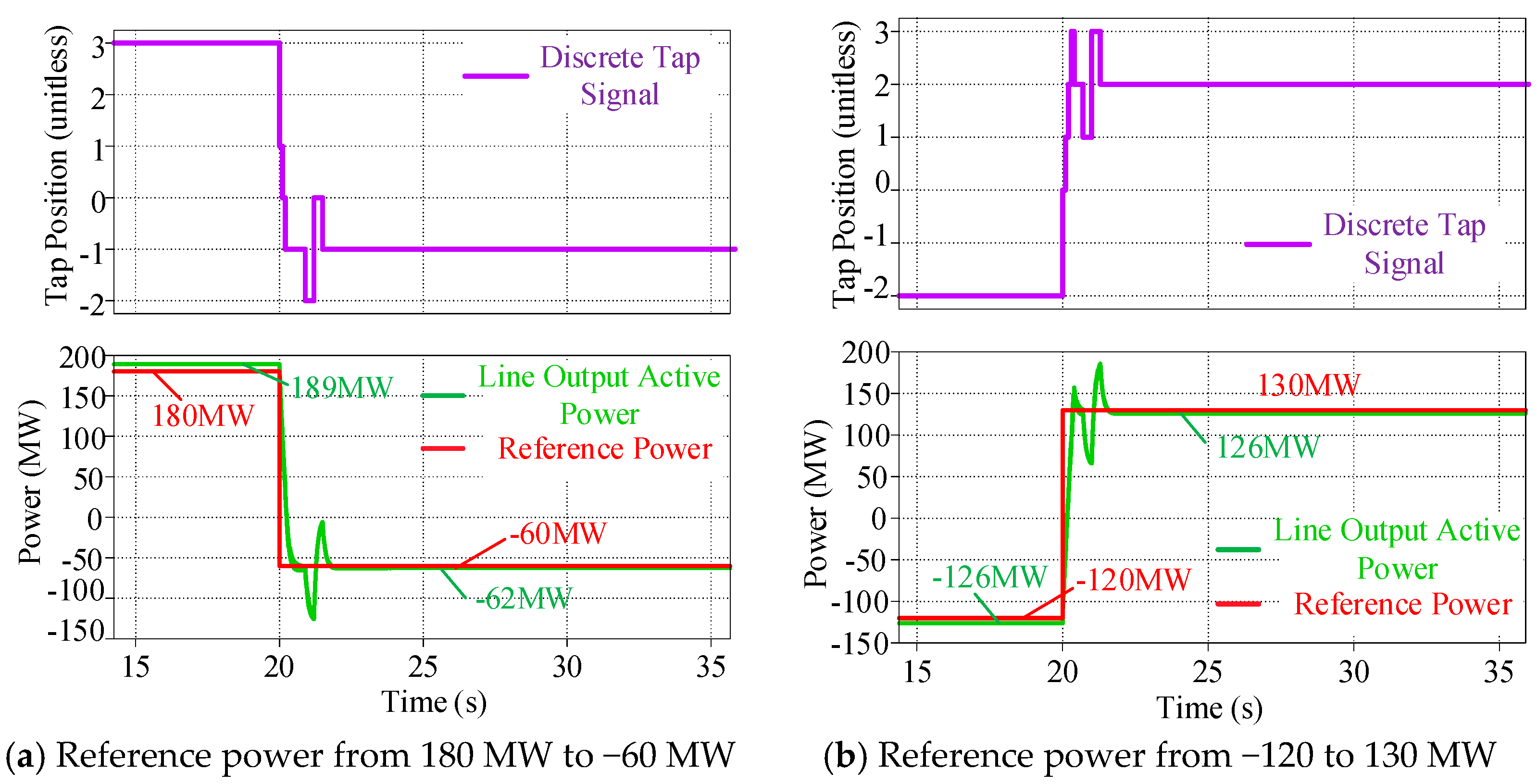
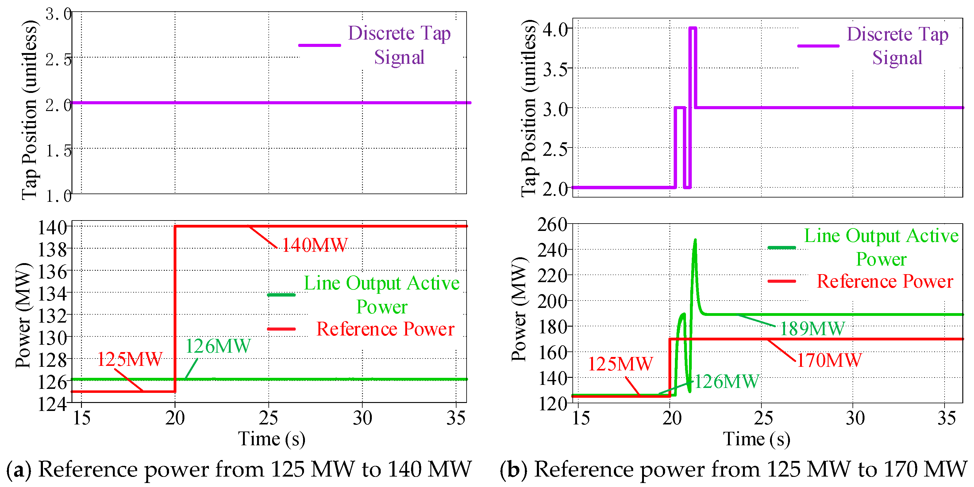
4. Simulation and Experimental Results

In order to verify the strategy, we use a two-node system for simulation verification. Each node points to a large system. The PST is installed on the connecting line of the two systems. There is a substation at both ends of the line. The network structure is shown in Figure 6.
Based on the network structure diagram, both ends of the line equipped with PST can be considered as two large systems. According to the hybrid open-loop control strategy proposed earlier, the network structure at both ends is equivalent, and the line model is built in PLECS. The accurate adjustment of the line active power by the PST control strategy is verified by simulation. The model structure is shown in Figure 6.
Figure 7 shows the complete topology of the mechanical phase-shifting transformer system using the proposed hybrid control strategy. The configuration features a two-terminal power network with defined sending and receiving ends. The three-phase transformer enables precise phase angle manipulation through multiple interconnection nodes. The control infrastructure includes a power flow calculator monitoring transmission parameters, a tap position optimization controller, and a reference power setting mechanism. An adaptive mode-selection switch enables seamless transitions between open-loop and closed-loop control based on threshold criteria. This topology validates the hybrid control methodology across various operational scenarios.
Figure 8, Figure 9, Figure 10 and Figure 11 shows the waveform of the selection process of the optimal tap position under different changes. We have chosen the 220 kV voltage level as the typical case for this study, based on its widespread application and representativeness in global power systems. This voltage level achieves an ideal balance between transmission capacity and economic efficiency, and is commonly used in regional transmission networks. By analyzing the system characteristics at this voltage level, our research findings can be effectively extended to similar grid infrastructures, providing a universally applicable reference value for the industry. The following section provides a detailed explanation of the process by which a mechanical phase-shifting transformer selects the optimal tap position at a 220 kV voltage level. As depicted in Figure 8, the voltage level of the line on which the mechanical phase-shifting transformer operates is 220 kV, with a maximum output tap position of 9. The initial control target for the line power flow is set at 450 MW. At the 20 s mark, the power flow control target is adjusted downward to 120 MW. The purple line in the figure represents the discrete tap position signal output by the tap position optimization controller, while the red line reflects the changes in the reference power set by the power flow control system. The green line shows the actual active power output of the line where the mechanical phase-shifting transformer is located.
In the initial phase of operation, the mechanical phase-shifting transformer maintains steady-state conditions, with the reference power of the line fixed at 450 MW. Due to the discrete nature of the phase-shifting transformer’s output, the actual active power output is recorded as 437 MW, which is very close to the reference power value. When the power flow control target is adjusted from 450 MW to 120 MW at 20 s, the mechanical phase-shifting transformer enters a brief tap position optimization phase. The system first enters the closed-loop control phase, as indicated by the blue dashed box in the figure. During this stage, the discrete tap position signal decreases rapidly, followed by a series of small fluctuations, before eventually stabilizing at tap position 2. In parallel, the active power output of the line fluctuates in response to the adjustments in the tap position signal, gradually stabilizing around 126 MW.
At this point, although the selected tap position appears to be close to optimal, it has not necessarily reached the optimal value. Consequently, the system proceeds to further optimize the tap position setting by entering the tap position probing phase. First, the system records the stable tap position 2 from the closed-loop control phase as the reference tap position, maintaining this setting for two seconds. During this time, the difference between the actual active power output of the line and the reference power is calculated and recorded as difference 1. Next, the tap position is reduced by one from the current reference tap position (i.e., the reference tap position is decreased by one), and the system remains in operation for an additional two seconds. At this point, it is evident that the output active power of the line is lower than the reference power, and the deviation between the two values is relatively large. This deviation is recorded as difference 2.
Subsequently, the system adjusts the tap position upward by one from the current reference tap position (i.e., the reference tap position is increased by one) and again maintains this setting for two seconds. In this instance, the output active power of the line exceeds the reference power, resulting in a significant deviation. This deviation is recorded as difference 3. By comparing differences 1, 2, and 3, it is found that difference 1 is the smallest. As a result, tap position 2 is ultimately selected as the optimal tap position for the MPST, corresponding to the line’s control target of 126 MW.
This optimization process highlights the precision with which the mechanical phase-shifting transformer adjusts the tap position setting to align with the required power flow control target. Through this systematic process of adjustment and evaluation, the system ensures that the most efficient operational configuration is achieved, improving overall system performance and stability.

5. Conclusions

Traditional MPSTs use a fixed tap position design with a limited number of tap settings, making continuous and precise adjustment impossible. This discrete regulation leads directly to insufficient control accuracy, failing to meet the requirements for precise power flow distribution in actual power grids. As a result, MPSTs cannot perform rapid and accurate phase angle adjustments in response to load fluctuations and generation variations in the system.
Thus, this paper proposes a hybrid strategy based on open-loop and closed-loop control to optimize the tap positions of MPSTs. This strategy allows the system to dynamically switch between open-loop and closed-loop control modes to respond to load variations in the system. In the closed-loop control phase, a PI controller is used to eliminate system errors in real-time, and the z-transform along with a zero-order hold circuit is employed to discretize continuous signals, ensuring smoothness and stability during the control process. In the open-loop control phase, the error in the PI controller is reset, and the output tap position is maintained to achieve precise optimization of the tap position, selecting the best tap position closest to the reference power.
Finally, a simulation was conducted on a typical two-node system with a voltage level of 220 kV. The results show that the proposed hybrid control strategy effectively mitigates the limitations caused by the discrete nature of MPST regulation. When there are significant changes in the power flow target, the system is able to select a tap position close to the optimal one, significantly reducing the deviation between actual power and reference power. Moreover, compared with the traditional closed-loop control method, the hybrid strategy demonstrates clear advantages in suppressing system oscillations and improving system stability. The simulation results confirm the effectiveness of the proposed control strategy in practical applications.

Author Contributions

Writing—original draft, J.D., X.W., J.L. and S.C.; Writing—review & editing, H.L. and C.W.; Project administration, J.L. and S.C. All authors have read and agreed to the published version of the manuscript.

Funding

This research was funded by [the Science and Technology Project of State Grid Corporation of China] grant number [J2024016].

Data Availability Statement

The original contributions presented in this study are included in the article. Further inquiries can be directed to the corresponding author.

Conflicts of Interest

Authors Jinjiao Lin, Shi Chen were employed by the State Grid Jiangsu Electric Power Co., Ltd. The remaining authors declare that the research was conducted in the absence of any commercial or financial relationships that could be construed as a potential conflict of interest.

References

  1. Boroyevich, D.; Cvetkovic, I.; Burgos, R.; Dong, D. Intergrid: A Future Electronic Energy Network? IEEE J. Emerg. Sel. Top. Power Electron. 2013, 1, 127–138. [Google Scholar] [CrossRef]
  2. Sreejith, S.; Simon, S.P.; Selvan, M.P. Analysis of FACTS devices on security constrained unit commitment problem. Int. J. Electr. Power Energy Syst. 2015, 66, 280–293. [Google Scholar] [CrossRef]
  3. Luburi, Z.; Pand, I.H. FACTS devices and energy storage in unit commitment. Int. J. Electr. Power Energy Syst. 2019, 104, 311–325. [Google Scholar] [CrossRef]
  4. Taher, M.A.; Kamel, S.; Jurado, F.; Ebeed, M. Optimal power flow solution incorporating a simplified UPFC model using lightning attachment procedure optimization. Int. Trans. Electr. Energy Syst. 2020, 30, e12170. [Google Scholar] [CrossRef]
  5. Sha, J.; Guo, C.; Rehman, A.U.; Zhao, C. A quantitative index to evaluate the commutation failure probability of LCCHVDC with a synchronous condenser. Appl. Sci. 2019, 9, 925. [Google Scholar] [CrossRef]
  6. Liu, J.; Xu, Z.; Yang, J.; Zhang, Z. Modeling and analysis for global and local power flow operation rules of UPFC embedded system under typical operation conditions. IEEE Access 2020, 8, 21728–21741. [Google Scholar] [CrossRef]
  7. Wang, H.F. Interactions and multivariable design of multiple control functions of a unified power flow controller. Int. J. Electr. Power Energy Syst. 2002, 24, 591–600. [Google Scholar] [CrossRef]
  8. Kawabe, K.; Yokoyama, A. Stability enhancement by multiple unified power flow controllers using wide-area information in the multi-machine power system. In Proceedings of the International Conference on Power System Technology, Hangzhou, China, 24–28 October 2010. [Google Scholar]
  9. Rashad, A.; Kamel, S.; Jurado, F.; Rihan, M.; Ebeed, M. Optimal design of SSSC and crowbar parameters for performance enhancement of Egyptian Zafrana wind farm. Electr. Eng. 2022, 104, 1441–1457. [Google Scholar] [CrossRef]
  10. Zhen, Q.; Gao, S.; Zhang, N.; Zhao, X.; Shi, Q.; Wang, Y.; Yang, L.; Liu, C. The design of TCPST operation parameter considering steady and dynamic characteristics. In Proceedings of the IEEE Sustainable Power and Energy Conference (iSPEC), Nanjing, China, 23–25 December 2021. [Google Scholar]
  11. Lu, W.; Chen, Y.; Zeng, K.; Li, J.; Chen, N.; Du, Z. A power flow control measure of across voltage levels based on TCPST in a distribution network with DG. In Proceedings of the 2022 12th International Conference on Power and Energy Systems (ICPES), Guangzhou, China, 23–25 December 2022. [Google Scholar]
  12. Hill, A.T. Thyristor Control of an Existing Phase-Shift Transformer; EPRI: Palo Alto, CA, USA, 1993. [Google Scholar]
  13. Minnesota Power. Static Phase-Shift Transformer Application and Concepts for Minnesota-Ontario Interconnection; EPRI: Palo Alto, CA, USA, 1992. [Google Scholar]
  14. Navabi, R.; Etemad, R.; Shayanfar, H.A. Self tuning fuzzy PI controller for UPFC to improve power system stability optimized by ant colony method. In Proceedings of the 2010 ECTI International Conference on Electrical Engineering/Electronics, Computer, Telecommunications and Information Technology, Chengdu, China, 28–31 March 2010. [Google Scholar]
  15. Al-Khanisi, N.; Heng, C. Thyristor controlled phase-shift transformer: A comprehensive survey. J. Southeast Univ. 2001, 17, 87–88. [Google Scholar]
  16. Wang, D.; Zhou, Q.; Ding, F. Analysis on Thyristor Firing Angle Influence of Discrete Regulated Fhase Shifter. Autom. Electr. Power Syst. 2014, 38, 121–126. [Google Scholar]
  17. Ding, T.; Bo, R.; Bie, Z.; Wang, X. Optimal Selection of Phase Shifting Transformer Adjustment in Optimal Power Flow. Power Syst. IEEE Trans. 2017, 32, 2464–2465. [Google Scholar] [CrossRef]
  18. Liu, J.; Hao, X.; Wang, X.; Chen, Y.; Fang, W.; Niu, S. Application of thyristor controlled phase shifting transformer excitation impedance switching control to suppress short-circuit fault current level. J. Mod. Power Syst. Clean Energy 2018, 6, 821–832. [Google Scholar] [CrossRef]
  19. Yan, Y.; Bai, H.; Chen, R.; Tolbert, L.M.; Wang, F. Unifying the Transformer Current in Multiple Phase Modulation Without Current Spike During Load Transients. IEEE Trans. Power Electron. 2022, 37, 14057–14061. [Google Scholar] [CrossRef]
  20. Chen, Z.; Han, X.; Wu, J.; Jiang, W. Study of Application Scenarios of Phase Shifting Transformers Considering Optimal Power Flow in Transmission Networks. In Proceedings of the 2023 3rd International Conference on Electrical Engineering and Control Science (IC2ECS), Hangzhou, China, 29–31 December 2023; pp. 210–214. [Google Scholar]
  21. Xu, Z.; Qin, R.; Ma, H.; Lu, J.; Tang, J.; Yang, Y. Research on the Optimal Regulation Strategy of Loop Closing Device Based on Phase Shifting Transformer. In Proceedings of the 2021 IEEE 5th Conference on Energy Internet and Energy System Integration (EI2), Taiyuan, China, 22–24 October 2021; pp. 1203–1208. [Google Scholar]
  22. Yuan, J.; Zhang, W.; Mei, J.; Gan, D.; Zhou, H.; Zheng, Y.; Liu, J. Independent Fast Phase Shifting Transformer: A Flexible and High-Precision Power Flow Controller. IEEE Trans. Power Deliv. 2023, 38, 4410–4421. [Google Scholar] [CrossRef]
  23. Wu, Q.; Wang, Y.; Zheng, Y.; Yang, Z.; Zhao, X.; Gao, B. Review on the Technology and Engineering Application of Phase Shifting Transformer. In Proceedings of the 2024 IEEE PES 16th Asia-Pacific Power and Energy Engineering Conference (APPEEC), Nanjing, China, 25–27 October 2024; pp. 1–5. [Google Scholar]
  24. Hurlet, P.; Riboud, J.C.; Margoloff, J.; Tanguy, A. French Experience in Phase-Shifting Transformers; CIGRE: Paris, France, 2006. [Google Scholar]
  25. IEC 62032-2005; Guide for the Application Specification and Testing of Phase-Shifting Transformers. International Electrotechnical Commission: Geneva, Switzerland, 2005.
  26. Patel, B.K.; Smith, H.S.; Hewes, T.S.; Marsh, W.J. Application of phase shifting transformers for daniel-mc knight. IEEE Trans. Power Deliv. 1986, 1, 167–173. [Google Scholar] [CrossRef]
  27. Spoorenberg, C.J.G.; Hulst, B.F.V.; Reijinder, H.F. Specific aspects of design and testing of a phase shifting transformer. In International Symposium on High Voltage Engineering; ISH: Rotterdam, The Netherlands, 2003. [Google Scholar]
  28. Carlini, E.M.; Manduzio, G.; Bonmann, D. Power flow control on the Italian network by means of phase-shifting transformers. CIGRE Sess. 2006, A2-206, 1–12. [Google Scholar]
  29. Siddiqui, A.S.; Khan, S.; Ahsan, S.; Khan, M.I. Application of phase shifting transformer in Indian network. In Proceedings of the 2012 International Conference on Green Technologies (ICGT), Trivandrum, India, 18–20 December 2012; pp. 186–191. [Google Scholar]
  30. Gajic, Z. Use of standard 87T differential protection for special three phase power transformers part 1: Theory. IEEE Trans. Power Deliv. 2012, 27, 1035–1040. [Google Scholar] [CrossRef]
  31. Khan, U.N.; Sidhu, T.S. A phase-shifting transformer protection technique based on directional comparison approach. IEEE Trans. Power Deliv. 2014, 5, 2315–2323. [Google Scholar] [CrossRef]
  32. Okon, T.; Wilkosz, K. Phase-shift transformer models for steady state analysis. In Proceedings of the 17th International Scientific Conference on Electric Power Engineering (EPE), Prague, Czech Republic, 16–18 May 2016; IEEE: New York, NY, USA, 2016; pp. 1–6. [Google Scholar]
Figure 1. Equivalent schematic diagram of a transmission line with a phase-shifting transformer installed.
Energies 18 03699 g001
Figure 2. Topology of MPST.
Energies 18 03699 g002
Figure 3. Dynamic response waveforms under pure closed-loop control.
Energies 18 03699 g003
Figure 4. Open-Loop and closed-loop hybrid control strategy diagram.
Energies 18 03699 g004
Figure 5. Control diagram based on open-closed loop fusion strategy.
Energies 18 03699 g005
Figure 6. Network structure with PST.
Energies 18 03699 g006
Figure 7. MPST simulation model.
Energies 18 03699 g007
Figure 8. Line transmission power reduction.
Energies 18 03699 g008
Figure 9. Line transmission power increase.
Energies 18 03699 g009
Figure 10. Transmission line power flow reversal.
Energies 18 03699 g010
Figure 11. Small change in line reference power.
Energies 18 03699 g011
Disclaimer/Publisher’s Note: The statements, opinions and data contained in all publications are solely those of the individual author(s) and contributor(s) and not of MDPI and/or the editor(s). MDPI and/or the editor(s) disclaim responsibility for any injury to people or property resulting from any ideas, methods, instructions or products referred to in the content.

