Article

Experimental Study of an Evaporative Cooling System in a Rotating Vertical Channel with a Circular Cross-Section for Large Hydro-Generators

1
State Key Laboratory of High-Density Electromagnetic Power and Systems, Institute of Electrical Engineering, Chinese Academy of Sciences, Beijing 100190, China
2
University of Chinese Academy of Sciences, Shijingshan District, Beijing 100049, China
*
Author to whom correspondence should be addressed.
Energies 2025, 18(14), 3681; https://doi.org/10.3390/en18143681
Submission received: 6 May 2025 / Revised: 29 June 2025 / Accepted: 10 July 2025 / Published: 12 July 2025

Abstract

With the evolution of hydroelectric generators toward larger capacity and higher rotational speeds, the significa++nt increase in power density has rendered rotor cooling technology a critical bottleneck restricting performance enhancement. Addressing the need for feasibility verification and thermodynamic characteristic analysis of evaporative cooling applied to rotors, this study innovatively proposes an internal-cooling-based evaporative cooling architecture for rotor windings. By establishing a single-channel experimental platform for a rotor evaporative cooling system, the key parameters of the system circulation flow under varying centrifugal accelerations and thermal loads are obtained, revealing the flow mechanism of the cooling system. The experimental results demonstrate that the novel architecture has outstanding heat dissipation performance. Furthermore, the experimental findings reveal that the flow characteristics of the medium are governed by the coupled effect of centrifugal acceleration and thermal load; the flow rate decreases with increasing centrifugal acceleration and increases with rising thermal load. Centrifugal acceleration reduces frictional losses in the heating pipe, leading to a decrease in the inlet–outlet pressure difference. Through the integration of experimental data with classic formulas, this study refines the friction factor model, with the modified formula showing a discrepancy of −10% to +5% compared with the experimental results. Finally, the experiment was rerun to verify the universality of the modified friction factor.

1. Introduction

With the increasing capacity and rotational speed of hydroelectric generators, rotor temperature rise has emerged as a critical bottleneck, directly affecting the design, manufacturing, and operational reliability of high-speed and high-power-density hydro-generators. Air cooling, which dissipates heat through the centrifugal air flow induced by rotor rotation or forced-air ventilation, remains the dominant cooling approach for hydro-generator rotors. The ventilation and heat dissipation calculations within generators are highly complex, falling under the multi-physics coupling of electromagnetics, heat transfer, and fluid dynamics. Current research on air-cooled rotors for hydro-turbine generators primarily employs computational fluid dynamics (CFD) methods [1,2]. Studies have performed multi-physics coupling simulations on rotors to analyze the effect of non-uniform heat transfer coefficients on the temperature distribution of rotor poles and have summarized the temperature distribution laws across various positions [3,4]. The air utilization efficiency of traditional air-cooling structures is low. When applied to high-power-density generators, a significant increase in cooling air volume is required to meet the rotor’s cooling demands. This increase not only further decreases heat exchange efficiency but also leads to a substantial rise in ventilation losses. Internal air-cooling, by optimizing the rotor’s air flow path, enables precise control of air volume modulation, thereby reducing windage losses [5,6]. However, the slender configuration of high-speed hydro-generators compromises their air-blowing capability and results in inadequate air ducts, making it difficult to supply sufficient cooling airflow to the generator. Furthermore, the elongated structure causes an uneven distribution of airflow along the rotor shaft, exacerbating temperature gradients and giving rise to more severe thermal deformation issues. Given the impact of windage losses, merely increasing the airflow volume does not necessarily enhance the cooling efficiency [7].
Internal water cooling represents an alternative approach for rotor windings, which involves circulating deionized water through the channels within rotor windings, leveraging water’s ultra-high specific heat capacity for convective heat exchange to remove heat from the windings. This method offers advantages such as high heat transfer efficiency and good winding temperature uniformity [8,9]. However, operational experience has shown that generators using internal water-cooling rotors have a significantly higher failure rate than those with air-cooled rotors. On one hand, the combined effects of centrifugal force and vibration easily cause joint leakage or pipeline friction rupture, and the leakage can lead to insulation damage and short circuits [10,11]. On the other hand, internal water cooling requires auxiliary facilities such as deionization systems and water pumps, increasing the complexity of the cooling system [12,13]. In high-speed generators, these drawbacks are amplified, posing challenges to the long-term reliable operation of the unit. Therefore, internal water cooling for rotors is not the optimal choice [14].
Evaporative cooling technology utilizes the latent heat of vaporization during liquid boiling for heat exchange and has seen numerous successful application cases in the field of internal cooling for hydro-generator stators [15,16]. There have been comprehensive studies on circulation, heat transfer characteristics, and coolant selection for stator evaporation cooling [17,18,19,20]. In contrast, research on rotor evaporation cooling is much scarcer. Given the development trend of hydro-generators, scholars have recently refocused their attention on rotor cooling and proposed immersive rotor evaporative cooling technology. Under rotation, this self-circulating structure demonstrates remarkably high cooling capacity and low circulation resistance, as centrifugal force drives coolant circulation without external pumps [14,21,22]. However, this structure completely seals the heat source in the liquid box, precluding the use of air cooling. Once the evaporative cooling system malfunctions, there is a risk of excessive temperature rise.
In response to these challenges, this research proposes a novel rotor evaporative cooling structure. In this design, channels containing cooling medium are embedded inside the rotor excitation windings. This design offers several benefits, including its lightweight nature and ease of installation. It not only serves as a viable approach for innovative generator designs but also provides a cost-effective solution for the retrofitting and upgrading of traditional vertical generators.
The theoretical foundation of this novel rotor evaporative cooling system is rooted in the principles of two-phase flow and heat exchange within rotating pipelines. Numerous scholars have conducted extensive research in this field, yielding noteworthy findings. For instance, a CFD study was conducted on the application of the novel structure examined in this research to hydroelectric generators [23]. However, this study primarily focused on vibration and model analysis, without involving two-phase heat transfer and flow, thus failing to support the study of the cooling system’s thermodynamic characteristics. Research on the heat transfer mechanism of rotating heat pipes under centrifugal acceleration up to 170 G has shown that increasing centrifugal acceleration enhances the cooling performance of heat pipes [24]. A similar study on rotating heat pipes that use nanofluids as the cooling medium was conducted and reached the same conclusion [25]. However, the structure, heat exchange mechanism, and circulation principle of the rotating heating pipe in the above studies are different from those of the rotor evaporative cooling system. A series of experiments were conducted on the boiling heat transfer characteristics in horizontal pipes. In the experiment, the direction of centrifugal acceleration was opposite to the direction of working medium flow, with a maximum centrifugal acceleration of 2G [26,27,28]. The study concluded that as the centrifugal acceleration increases, the thermal loss of the two-phase flow in the pipeline intensifies, while the single-phase flow in the pipeline is less affected. In addition, the flow resistance inside the pipe is influenced by the number of phases present in the flow, and the frictional head loss of the two-phase flow is significantly affected by centrifugal acceleration. However, the centrifugal acceleration condition in this study is relatively small, and it cannot cover the design requirements of hydroelectric generators. Furthermore, the examined pipe was orthogonal to the direction of gravity. This alignment diverges from the characteristics of the cooling pipes in vertical generators, which align parallel to the rotation axis. Therefore, the findings cannot be precisely applicable to vertical hydroelectric generators. To tackle the challenge of in-tube boiling being difficult to observe, scholars have performed simulation studies on horizontal pipes, numerically calculating the transient flow and heat transfer characteristics of subcooled boiling [29,30,31]. However, these studies are generally conducted under stationary conditions, failing to account for the influence of complex unsteady flows induced by rotational motion. In the field of experimental research, current visualized horizontal pipe boiling flow experiments are predominantly performed on static platforms, whereas studies on the impact of high centrifugal acceleration on flow and heat transfer characteristics remain limited. For subcooled boiling experiments in horizontal channels, the bubble distribution perpendicular to the heating surface and local porosity have been measured, revealing that heat flux density and mass flow velocity are the main factors affecting the flow pattern [32]. In addition, the effects of heating surface oxidation state, mass flow rate, and channel height on the flow and heat transfer characteristics of subcooled boiling have been explored [33]. Additionally, studies have analyzed the mechanism by which flow and heat transfer parameters (e.g., channel pressure, wall superheat, flow velocity, and liquid subcooling degree) influence the bubble rising diameter during the boiling process [34]. When studying rotor evaporative cooling systems, it is necessary to introduce dimensionless numbers containing rotational speed into the research on two-phase flow in pipes. One study introduced the Rossby number, and CFD was used to analyze the rotating two-phase flow patterns [35]. Another study introduced the rotational Reynolds number and reported that the frictional pressure drop of two-phase flow in rotating channels is negatively correlated with rotational speed and positively correlated with the Reynolds number in the pipe [36].
This study constructs a single-channel experimental platform to study the cooling mechanism of a rotor evaporative cooling system. In this research, a theoretical analysis and experimental research are conducted, and a parametric quantitative analysis is adopted to study the laws of the influence of centrifugal acceleration and thermal load on the system flow characteristics. This research provides a theoretical framework and design criteria for the application of rotor evaporative cooling technology.

2. Basic Theory

Figure 1 depicts the configuration of a single pole in the rotor evaporative cooling system proposed in this study. The circulation system comprises a condenser and a pole with multiple coolant-filled pipes axially embedded along the rotor coils. All of the heating pipes converge into a vapor pipe connected to the upper inlet of the condenser. The condenser is either enclosed within the pole support or designed as a monolithic structure with it. The condenser’s lower outlet connects to the heating pipes via a liquid return pipe, forming a closed-loop cooling circuit. All components are mounted on the shaft through the pole support, ensuring concentric rotation during operation. During generator shutdown, the coolant accumulates in the lower half of the structure under gravitational influence. Upon startup, the liquid coolant rapidly fills the pole’s heating pipes as the rotational speed ramps up.
Based on the structure depicted above, taking a single heating pipe as the research object, a schematic diagram of a single-channel evaporative cooling system is obtained, as shown in Figure 2. The assembly of the condenser, return pipe, vapor pipe, and heating pipe constitutes a hermetically sealed cycling system that revolves with the shaft. Under the effect of centrifugal acceleration, the liquid medium, which has a much higher density, is propelled towards the periphery of the axis. Upon exiting the condenser, the liquid medium is channeled through the return pipe into the heating pipe, where it undergoes thermal elevation in temperature, subsequently flowing into the vapor pipe and experiencing flash evaporation. The vapor medium, entraining a small amount of liquid medium, flows towards the condenser, where it sheds heat, reverts to a liquid state, and exits via the condenser’s outlet. Thus, a cycle flow is established. The density difference between the medium in the return pipe and the vapor pipe generates a flow head, serving as the driving force for the cycle flow.
For the rotor evaporative cooling system, the heat absorbed by the working medium is almost entirely used to increase fluid enthalpy, enabling the fluid to have work capacity and, thus, drive the entire cycle. In the evaporation section, the coolant absorbs excitation losses, with q > 0. The temperature of the coolant rises, and partial boiling occurs. The absorbed heat partly increases the enthalpy of the coolant, and the other part is converted into kinetic energy and potential energy through steam expansion. Taking a certain mass of the medium as the research object, a thermodynamic equilibrium equation is established based on the coolant states at the inlet and outlet of the heating pipe. The energy equations of the medium in each stage of the circulation flow are as follows [21,37,38]:
q Δ u = P b v b P a v a + 1 2 · c f b 2 c f a 2 + g l b l a + a b a r r d r + w i
a r r = π n N 30 2 r
In this formula, q represents the power absorbed from the external environment, and for this research, this is the electric heating power; u is the internal energy of the system in the time unit; m ˙ is the mass flow rate of the medium; P is the pressure; v is specific volume of the medium; c f is the flow rate of the medium; g is the gravitational acceleration; a r r is the centrifugal acceleration; n N is the rotating speed; r is the radius of rotation; and w i is the internal work. The subscript a indicates the parameters are at the inlet; for b , the parameters are at the outlet.
The frictional head loss of incompressible fluids in circular pipes is calculated using the Darcy–Weisbach equation [39,40]:
Δ P L = λ · ρ · c f 2 2 · D + ρ g
c f = m ˙ ρ · π · D 2 2
λ = 64 R e                                                                                                 R e < 2300 1 2 l o g 10 2.51 R e λ 2                       3000 < R e < 80 D ε 1 2 l o g 10 2.51 R e λ + ε 3.7 D 2               80 D ε < R e < 4160 D 2 ε 0.85 1 1.74 + 2 l g D 2 ε 2                               80 D ε < R e < 4160 D 2 ε 0.85
R e = ρ c f D μ
Here, λ is the friction factor; ρ is the density of the liquid medium; L is the length of the pipeline; D is the diameter of the pipeline; μ is the viscosity; and ε is the absolute roughness of the pipeline’s inner wall.
For turbulent flows with 4000 < R e < 10,000, the Blasius formula is commonly used to calculate the friction factor λ [40,41]:
λ = 0.3164 R e 0.25                                           4000 < R e < 10 , 000
This experiment is conducted under rotational conditions where centrifugal acceleration is much greater than gravitational acceleration. A high centrifugal acceleration induces a significant radial pressure gradient in the pipe, driving the coolant to generate a secondary flow, which intensifies fluid turbulence, destabilizes the flow pattern, and decreases the outflow rate and frictional losses. Therefore, by treating centrifugal acceleration as an additional term in the pressure difference calculation, the friction factor formula is revised based on the Blasius equation, incorporating this dynamic effect.
The heating pipe is parallel to the shaft; therefore,
Δ P 1 L 1 = λ c D 1 · ρ 1 c f 2 2 + ρ 1 g
λ c = k c · 0.3164 R e 0.25                                 4000 < R e < 10 5
k c = 1 + 2.56 + 0.008 R e 0.03 a r r g 0.03
Here, Δ P 1 is the pressure difference between the inlet and outlet of the heating pipe, Pa; λ c is the modified friction factor; L 1 is the length of the heating pipe in m; and k c is the correction coefficient.
The correction coefficient k c consists of two terms; the first term is the basic term based on the Blasius formula, and the second term is the increase term considering the influence of centrifugal acceleration and the Reynolds number.

3. Experimental Platform Design

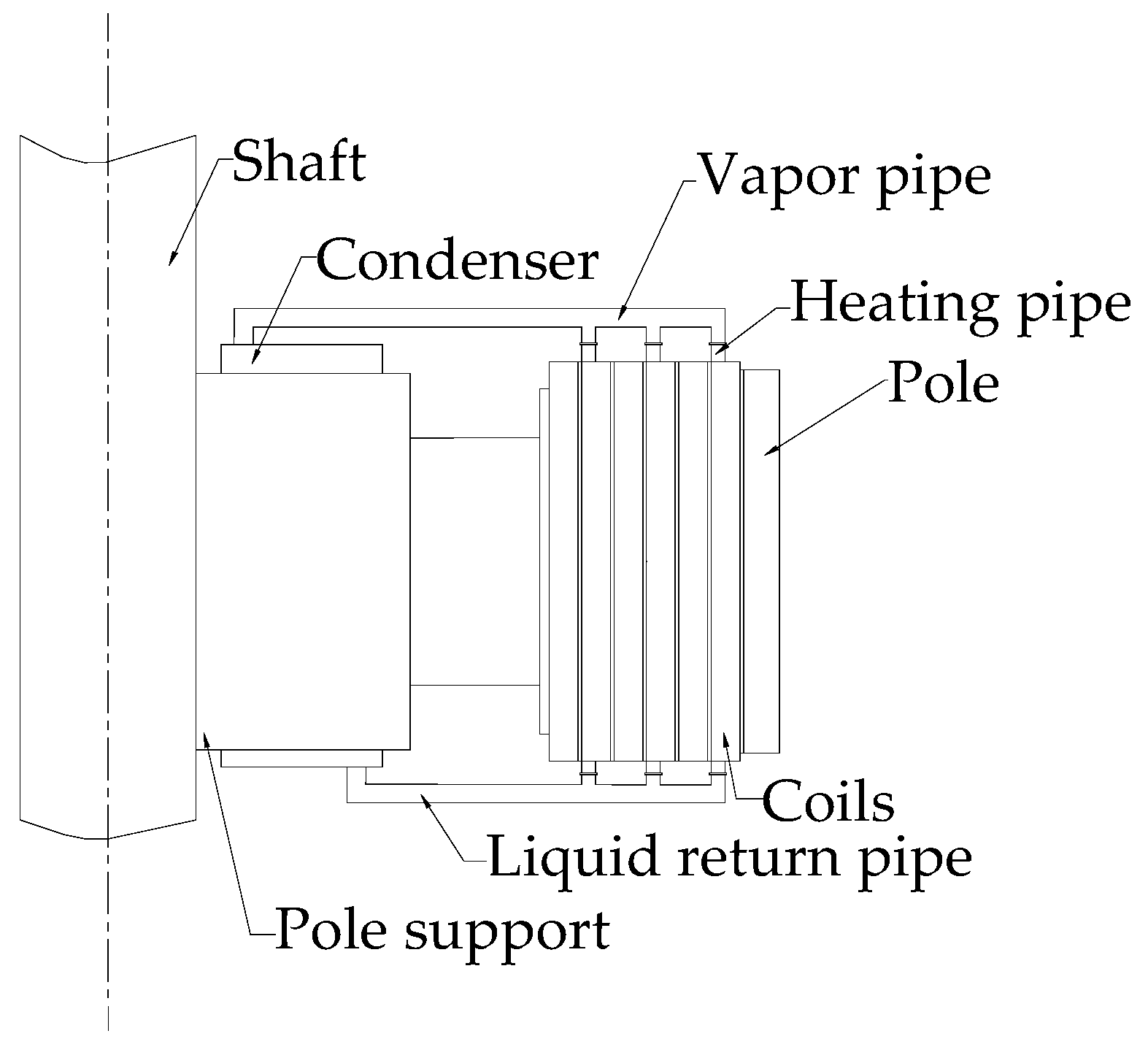
3.1. Basic Structure and Measurement Points

To study the circulation characteristics of the rotor evaporative cooling system in a vertical channel, a single-channel experimental platform was constructed, as shown in Figure 3. The platform is mainly composed of a frame, shaft, sliding ring, experimental part, counterweight part, and timing belt driving system. The experimental part and counterweight part are installed on the shaft and rotate concentrically with it. The shaft is driven by a motor through a timing belt transmission mechanism. The sliding ring provides a power supply and measurement signal transmission.
The experimental part consists of a heating pipe, a vapor pipe, a liquid return pipe, and a condenser. The material of the heating pipe is brass, with a length of 400 mm, an inner diameter of 6 mm, and an outer wall diameter of 22 mm. The required thermal load for the experiment is applied through a heating film attached to the outer wall surface. The vapor pipe and the liquid return pipe are transparent polycarbonate pipes with an outer diameter of 12 mm and an inner diameter of 8 mm. The condenser is of the shell-and-tube type, using water cooling as the secondary cooling method.
Temperature sensors T1~T4 and pressure sensors P1~P4 are set both at the inlet and outlet of the heating pipe and condenser, respectively, to measure the inlet and outlet temperature and pressure of each section of the circulation pipeline. Starting from the heating pipe inlet, a pair of small holes are drilled every 50 mm along the axial direction of the pipeline on the outer wall surface, and 14 platinum RTD sensors are installed to measure the outer wall temperature T w of the pipeline. The heating pipe, vapor pipe, and liquid return pipe are wrapped with an insulating layer to minimize the influence of air cooling. Table 1 lists the specific parameters of the sensors used in the experiment.
The mass flow rate is obtained based on the following principle of thermal flowmeters:
m ˙ = Q e f f C p T b T a
Here, C p is the specific heat capacity of the liquid medium, T b is the heating pipe outlet temperature, and T a is the inlet temperature.

3.2. Experimental Conditions

In this experiment, the thermal load on the outer wall of a heating pipe and centrifugal acceleration of the heating pipe are employed as parameter variables. The range selection for these variables is based on the water-cooling unit in the Bieudron hydroelectric station [10]. Twenty sets of experimental conditions were designed considering the advancement of research and the safety requirements, as shown in Table 2. The thermal load is 200 W~500 W, and the centrifugal acceleration is 40 G~80 G (40 times the gravitational acceleration to 80 times the gravitational acceleration).

4. Experimental Results and Discussion

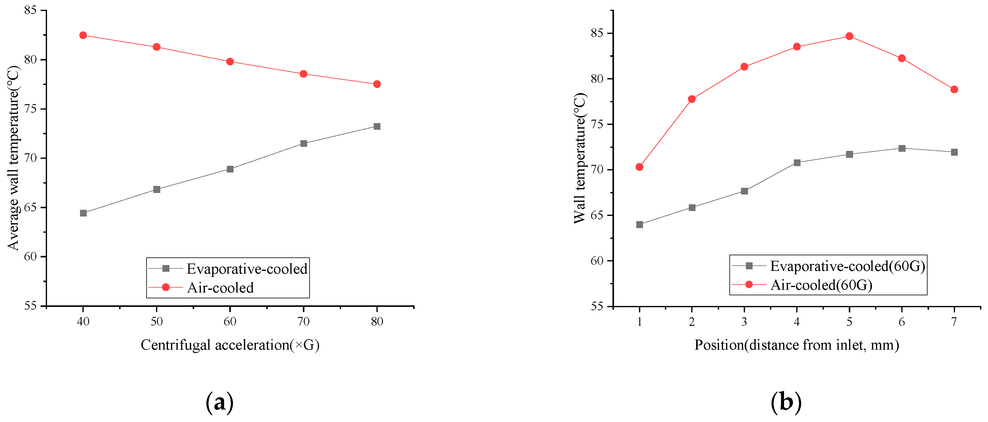
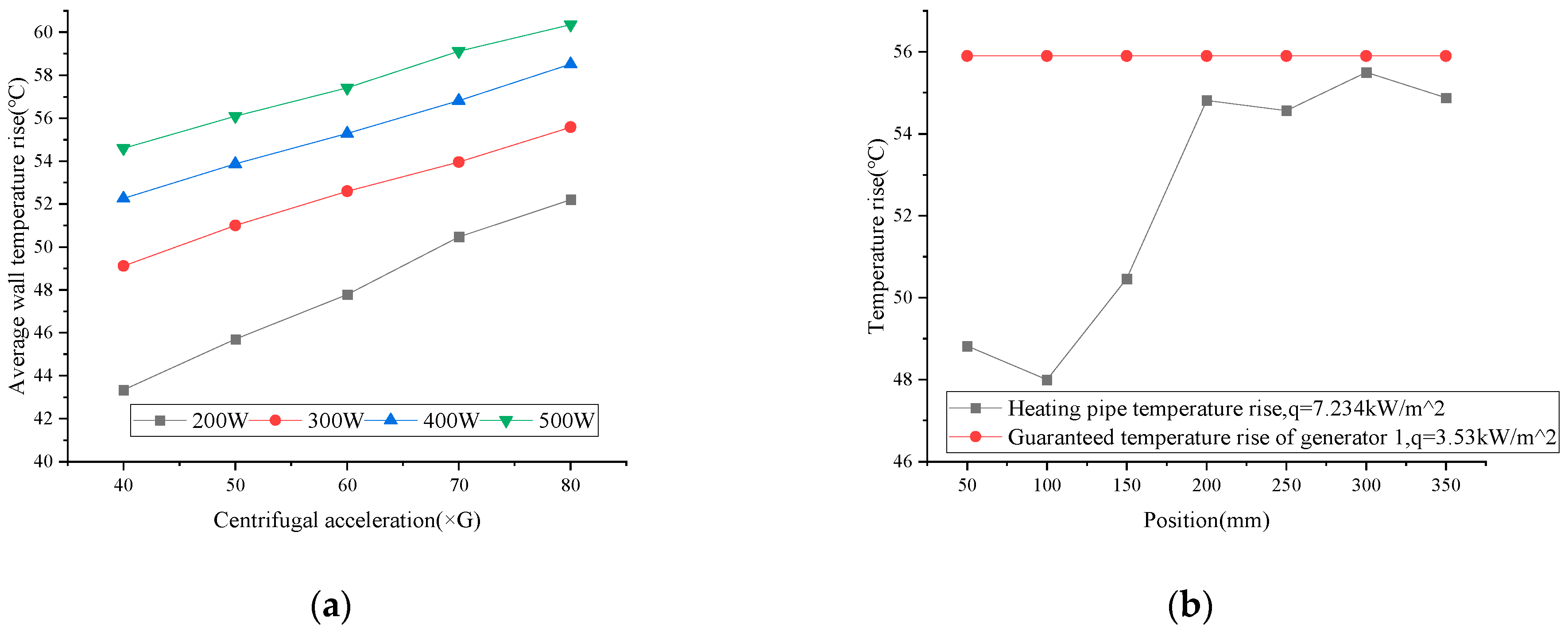
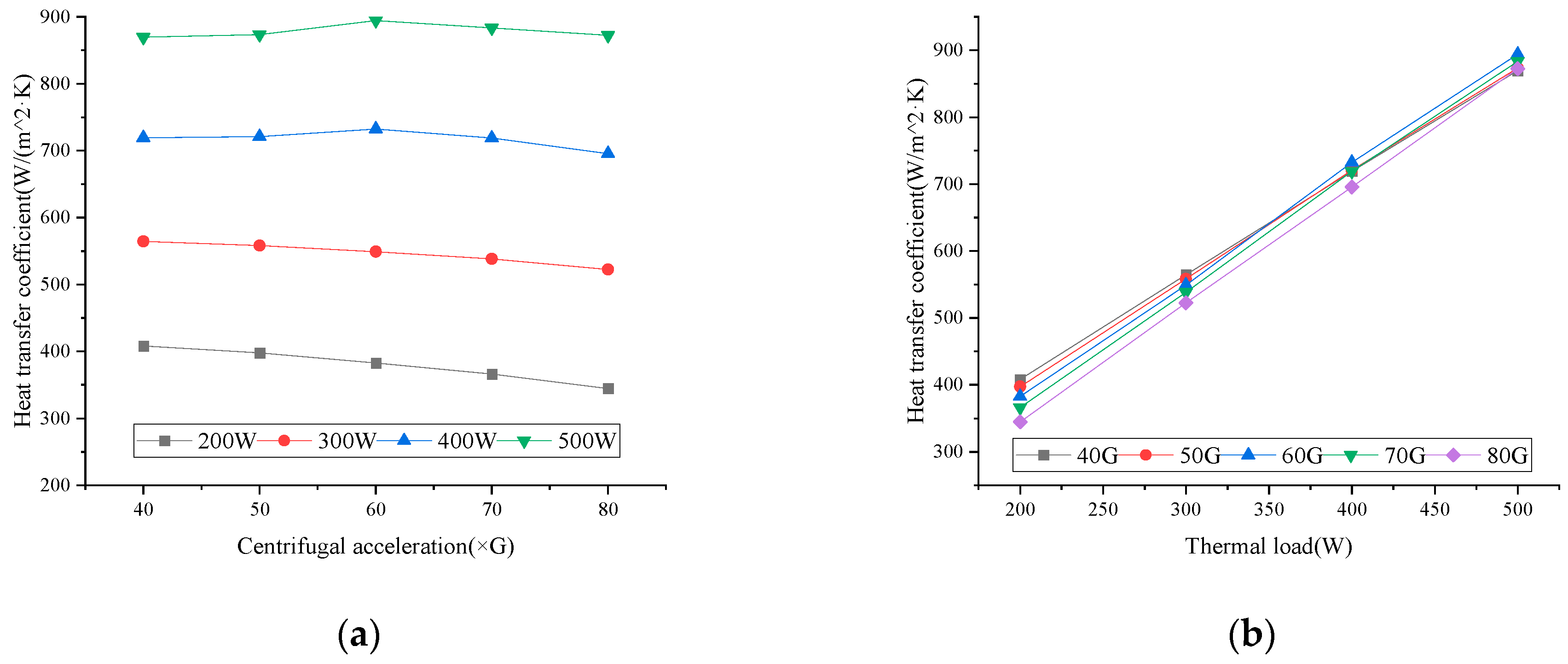
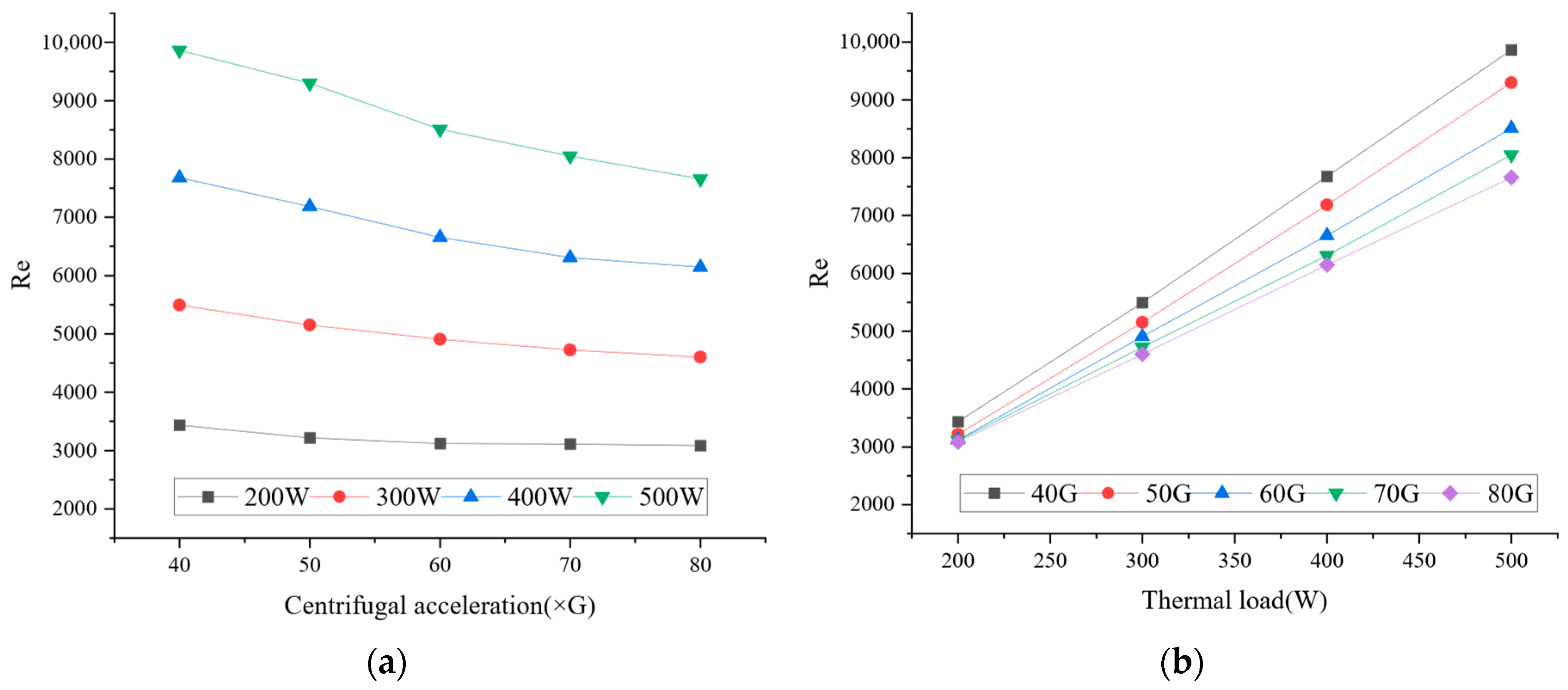
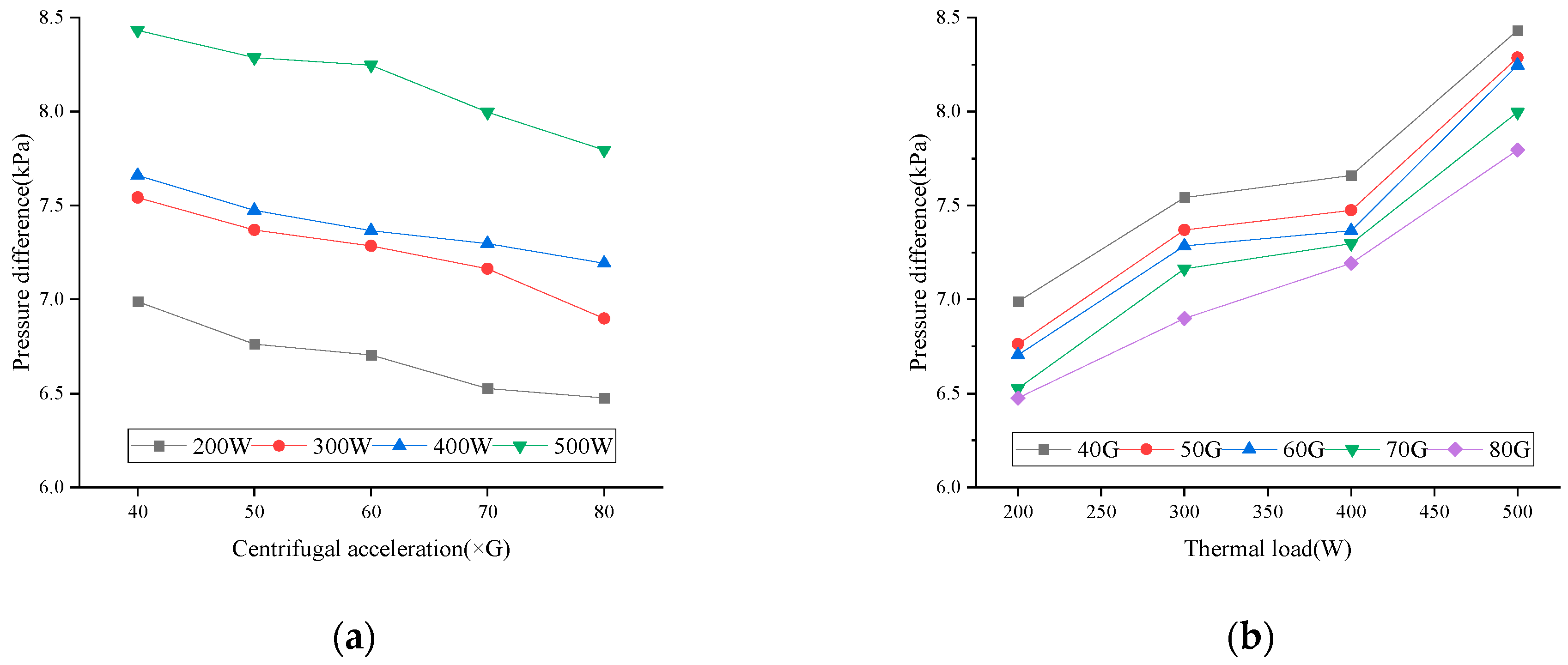
4.1. Experimental Results

First, as a control group, a heating pipe identical to the one on the experiment platform without any surface insulation coating was used, relying solely on air-cooling for heat dissipation. In the experiment, a thermal load of 100 W had already caused the maximum wall temperature of the air-cooled heating pipe to approach 100 °C. To protect the sensors, the applied power boundary condition was set to 100 W for controlled variable comparisons. Figure 4a shows that within the experimental range of centrifugal acceleration and under the same thermal load, the surface temperature of the evaporatively cooled heating pipe is consistently lower than that of the air-cooled pipe. Figure 4b illustrates the temperature uniformity along the pipe wall for both pipes under identical thermal load and centrifugal acceleration conditions (100 W/60 G). The temperature in the middle section of the air-cooled heating pipe is significantly higher than at its ends, whereas the evaporatively cooled heating pipe exhibits better temperature uniformity.
Figure 5a illustrates the variation in the average temperature rise in the heating pipe with centrifugal acceleration, showing that the average temperature rises as centrifugal acceleration rises. Figure 5b compares the wall temperature rise in the heating pipe with the guaranteed temperature rise of the rotor winding in a large, air-cooled hydro-generator unit under similar centrifugal acceleration [24]. It can be seen that even when the heat flux is twice that of the air-cooled unit, the wall temperature rise in the evaporative cooling pipe is still lower than that of the air-cooled unit, and the fluctuation range of the pipe wall temperature is smaller, indicating superior cooling capacity.
Figure 6 shows the mainstream temperature of the working medium inside the heating pipe under various thermal loads at a centrifugal acceleration of 40 G. The experimental results indicate that under high-speed rotation, due to the significant increase in pressure of the working medium within the heating pipe caused by centrifugal acceleration, the mainstream temperature of the working medium remains consistently lower than the saturation temperature corresponding to the pressure inside the pipe, preventing the occurrence of saturated boiling.
The wall temperature remains higher than the saturation temperature while the fluid is in a subcooled state, leading to the possible coexistence of subcooled boiling and single-phase convective heat transfer in the pipe. The convective heat transfer coefficients on the inner wall of the heating pipe were calculated using Newton’s law of cooling, and the average heat transfer coefficients under various working conditions are shown in Figure 7. It can be observed that the average heat transfer coefficient of the pipe inner wall decreases with the increase in centrifugal acceleration. This is because the increase in centrifugal acceleration raises the internal pressure, leading to an increase in the saturation temperature of the coolant. The higher degree of subcooling raises the proportion of single-phase convection, thus reducing the heat transfer coefficient. When flash evaporation occurs in the vapor pipe, it sharply increases the flow velocity of the coolant in the heating pipe, affecting the convective heat transfer coefficient. The intensification of flashing is directly influenced by the increase in loading power, so the heat transfer coefficient in the pipe increases with the rise in loading power.
Based on Formula (8), the mass flow rate of the working medium in the heating pipe is shown in Figure 8. The flow rate of the medium decreases with increasing centrifugal acceleration and increases with increasing power load. Due to the effect of centrifugal acceleration, a radial pressure gradient is induced in the pipe, driving the coolant to generate secondary flow and diminishing the outward flow rate of the fluid. On the other hand, according to the continuity equation, when the flow channel cross-section remains constant, an increase in fluid density leads to a decrease in flow rate. The increase in thermal load exacerbates the intensity of flashing in the vapor pipe. Then, a large amount of liquid working medium undergoes a phase transition to become a gaseous working medium, causing a sudden pressure to drop in the vapor pipe. As a result, the significant surge in the pressure head drives a large quantity of coolant in the heating pipe to flow rapidly into the vapor pipe, leading to an increase in the mass flow rate with the rise in the loading power.
According to Formula (6), the Reynolds number of the working medium in the pipe is calculated, as shown in Figure 9. It can be seen that the Reynolds number of the working medium in the pipe ranges from 3000 to 10,000, indicating turbulent flow in the heating pipe.
The variation in the pressure difference across the heating pipe inlet and outlet is shown in Figure 10. It can be observed that the pressure difference decreases with the increase in centrifugal acceleration and increases with the rise in thermal load. When centrifugal acceleration increases, the coolant velocity decreases and the density difference decreases, leading to a decrease in the pressure difference across the heating pipe. Conversely, as the thermal load increases, flashing in the vapor pipe intensifies, enhancing the density difference across the inlet and outlet, thereby increasing the pressure difference. Within the range of experimental conditions, the highest pressure difference is 8.43 kPa, which occurs under the condition of 500 W/40 G.
Figure 11 presents the correlation among pressure difference, mass flow rate, centrifugal acceleration, and thermal load, depicted through a three-dimensional color-mapped surface plot. The data suggest that a decrease in centrifugal acceleration and an increase in thermal load correlate with a higher flow rate within the heating pipe. As the flow rate escalates, there is a consequent increase in the Reynolds number and intensifying turbulence. This intensification leads to an increase in losses along the channel, thereby augmenting the pressure difference between the inlet and outlet.

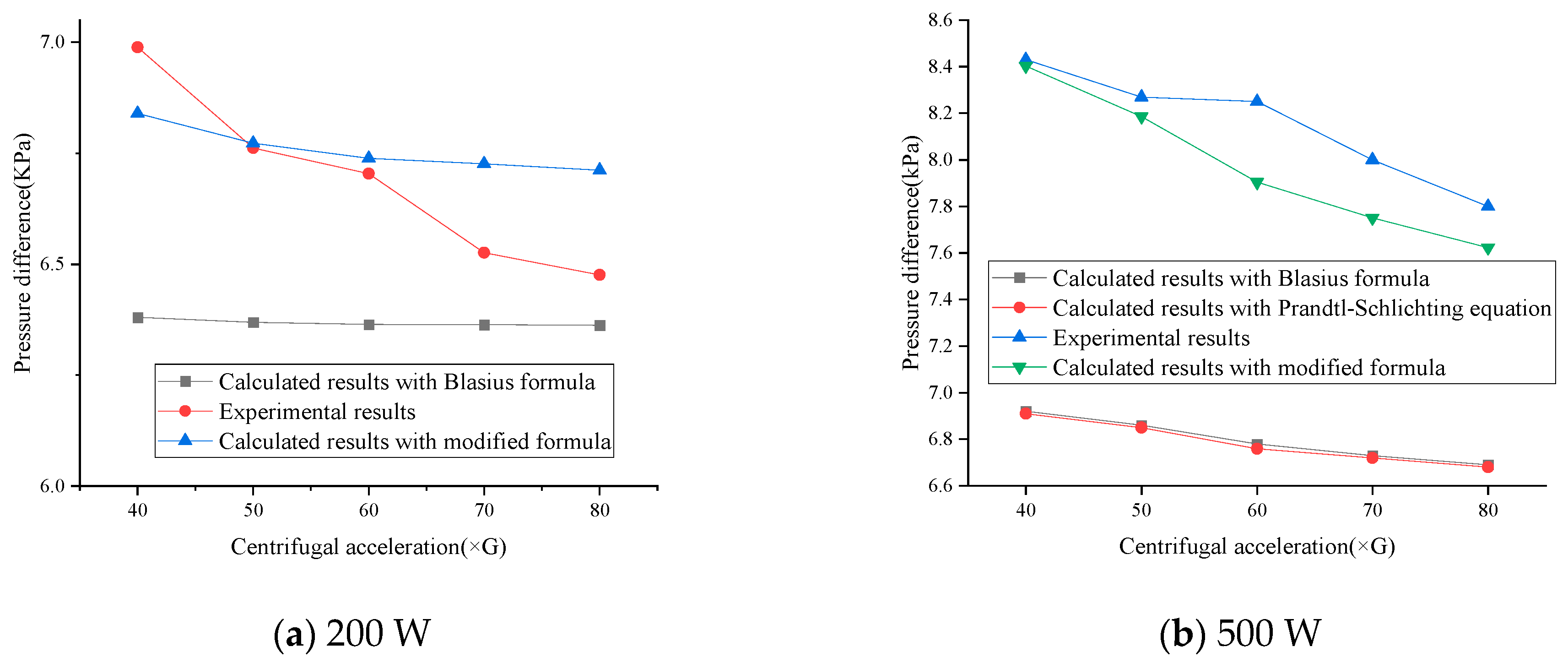
4.2. Friction Factor Modification and Experimental Verification

The inner wall surface of the heating pipe was manufactured using the EDM process, and the absolute surface roughness is 0.02 mm. The pressure differences between the inlet and outlet of heating pipe under the 500 W thermal load are calculated using classic formulas and then compared with the experimental data to verify their consistency. The results are shown in Table 3. It can be seen that there is a significant discrepancy between the results of the classical formulas and the experimental results, and the Blasius formula performs slightly better.
The comparison of the pressure difference calculation results before and after using the modified friction factor with the experimental results under the thermal loads of 200 W and 500W is shown in Figure 12. The pressure difference calculated with the modified friction factor fits well with the experimental results.
As demonstrated in Figure 13, the modified formula exhibits a relative error range of −10% ~ +5% between its predicted values with the experimental results across all test conditions.
The experimental results, in conjunction with Formulas (10)–(12), demonstrate that under the same thermal load, while the Reynolds number and flow rate decrease as centrifugal acceleration increases, this change is marginal. The primary impact of increased centrifugal acceleration is on the second term of the correction factor, while the base term remains literally unaffected. Consequently, both the friction loss and pressure difference within the heating pipe section decrease with the increase in centrifugal acceleration. When the centrifugal acceleration remains constant, an increased thermal load significantly elevates the flow rate, correspondingly augmenting the first term of the correction factor. As the pressure difference is positively correlated with the square of the flow rate, an increased thermal load results in a substantial rise in pipeline friction loss.
To verify the universality of the correction coefficient, the liquid filling amounts were adjusted to 1.2× and 2× the reference volume, and experiments were rerun under identical thermal load and centrifugal acceleration conditions. As illustrated in Figure 14, due to the unique characteristic that the rotating cooling pipeline operates in a high-centrifugal-acceleration field, the Reynolds numbers of the working medium in the heating pipe remain within the range of 3000–10,000 across different filling amounts.
Figure 15 compares the calculated and experimental pressure differences across the heating pipe inlet/outlet under thermal loads of 200 W and 500 W with 1.2 times and 2 times the baseline liquid filling amount. The results show that even with increased filling volumes, calculations using the correction coefficient considering the Reynolds number and centrifugal acceleration still exhibit better agreement with the experimental data under rotational conditions than the classical formulas.

5. Conclusions

5.1. Key Findings

This study presents an innovative rotor evaporative cooling structure and constructs a single-channel experimental platform. A series of control experiments show that evaporative cooling rotors have better cooling capacity and temperature uniformity than air cooling rotors. First, by comparing an air-cooled heating pipe with an evaporatively cooled heating pipe under the same thermal load, it was found that the average wall temperatures of the evaporatively cooled pipe at different centrifugal accelerations were all lower than those of the air-cooled pipe, with a temperature difference above 4.26 °C and the maximum reaching 18.03 °C. Moreover, after fixing the centrifugal acceleration at 60 G, the maximum temperature difference along the wall of the evaporatively cooled pipe was 8.52 °C, while that of the air-cooled pipe was 14.28 °C. Subsequently, the wall temperature rise in the evaporatively cooled pipe was compared with the guaranteed temperature rise in a rotor of a certain large hydro-generator with similar centrifugal acceleration. The results demonstrate that, even when the heat flux was doubled compared with that of an air-cooled unit, the maximum wall temperature rise in the cooling pipe was 9.7% lower than the guaranteed winding temperature rise in the air-cooled unit. This significant finding strongly validates the outstanding heat dissipation performance of the proposed structure. Furthermore, to investigate the flow and heat transfer mechanism within the pipe, the above results were obtained under the condition that the heating pipe surface was covered with a thermal insulation layer to exclude the air-cooling effect. That is to say, when applied in the field of actual generator rotors, in which heating pipes are embedded in the rotor coils, and in conjunction with the air-cooling technology for rotor poles, it can be anticipated that the rotor temperature rise will be further reduced.
Furthermore, the research reveals that the flow characteristics of the medium within the system are jointly influenced by centrifugal acceleration and thermal load. Specifically, the flow rate exhibits an inverse relationship with centrifugal acceleration, decreasing as centrifugal acceleration increases, while it is positively correlated with thermal load, increasing as the thermal load rises. Centrifugal acceleration reduces the frictional losses in the heating pipe, consequently decreasing the pressure difference between the pipe’s inlet and outlet. As the thermal load intensifies, the flash evaporation of the coolant becomes more pronounced, driving a notable increase in the flow rate.
Under the experimental conditions of this study, the heat transfer coefficient demonstrates greater sensitivity to thermal load variations. At constant centrifugal acceleration, a 100% increase in thermal load induces a maximum heat transfer coefficient variation of 311.07 W/(m2·K) (at 40 G). In contrast, with fixed thermal load, a 100% increase in centrifugal acceleration results in a maximum variation of only 63.45 W/(m2·K) (under a 200 W thermal load).
Similarly, the flow rate exhibits higher sensitivity to thermal load fluctuations. When the centrifugal acceleration is held constant, a 100% increase in thermal load yields a maximum flow rate change of 0.012 kg/s (at 40 G). Conversely, with thermal load fixed, a 100% increase in centrifugal acceleration leads to a maximum flow rate change of merely 0.0062 kg/s (under a 500 W thermal load).
In a rotating pipe flow, centrifugal acceleration influences friction loss. This study refines the friction factor by combining experiments with classic formulas. The discrepancy between the calculated results of the modified formula and the experimental data ranges from −10% to +5%.

5.2. Future Work

Compared with air cooling, evaporative cooling exhibits higher cooling capacity. In contrast to water cooling, it features a simpler system, higher reliability, and insulating properties of the working medium. Therefore, applying evaporative cooling technology to the rotor coils in high-power-density hydro-generators is a highly rational choice. Due to the limitations of experimental conditions, compared with future high-parameter units, there is still a gap in the centrifugal acceleration that this experimental platform can provide. The research results obtained are only applicable to the experimental conditions described in Table 2. In the later stages, it is necessary to expand the research boundaries and combine experiments and simulations to study the applicability of rotor evaporative cooling technology under higher centrifugal accelerations.
Within the experimental conditions of this study, the higher the coolant velocity, the lower the pipeline temperature and the greater the heat transfer coefficient of the heating pipeline wall, which is because the increase in flow velocity enhances the single-phase convective heat transfer, which seems to be beneficial. However, for evaporation cooling systems using low-boiling-point coolants, excessively increasing the flow velocity will instead reduce the proportion of subcooled boiling in the pipe. Evaporative cooling systems prefer to utilize the latent heat of vaporization to remove heat, as the heat transfer coefficient of coolant phase change is much higher than that of single-phase convective heat transfer. Therefore, a more optimal approach is to reasonably design the pipeline and appropriately reduce the flow velocity of the coolant to enhance the subcooled boiling in the heating pipe, which is an important part of future work.
From an application perspective, this study focuses on the heat transfer and flow mechanism of a single pipeline in the evaporative cooling system for rotors with internal pipe cooling. In the future, there is still a vast research space for the application of multiple pipelines working in coordination in hydro units. Additionally, as a forward-looking study prepared for practical engineering applications, the economic analysis of this technology is also of great necessity.

Author Contributions

R.L.: Conceptualization; Data curation; Formal analysis; Investigation; Writing—Original draft; Methodology. L.R.: Funding acquisition; Project administration; Writing—Review and Editing. All authors have read and agreed to the published version of the manuscript.

Funding

This research received no external funding.

Data Availability Statement

The original contributions presented in this study are included in the article. Further inquiries can be directed to the corresponding author.

Conflicts of Interest

The authors declare no conflicts of interest.

Nomenclature

ar(r)centrifugal acceleration (m2/s)
cflow rate (m/s)
Ddiameter (m)
ggravitation acceleration (m2/s)
kccorrection coefficient
Llength (m)
m ˙ mass flow rate (kg/s)
nNrotating speed (r/min)
Ppressure (Pa)
ΔPpressure difference (Pa)
qelectric heating power (W)
rradius of rotation (m)
uinternal energy (W)
vspecific volume (m3/kg)
wiinternal work (W)
Greek letters
εabsolute roughness of pipeline inner wall (mm)
λfriction factor
εcmodified friction factor
μviscosity (Pa·s)
ρdensity (kg/m3)
Subscripts and superscript
1heating pipe position
ainlet
boutlet

References

  1. Zhu, D.; Guo, W.; Zhang, X. Study on simulation of fluid-solid thermal coupled fields for the ventilation and heat rejection system of hydrogenerator. J. Hydroelectr. Eng. 2009, 28, 5. [Google Scholar]
  2. Staton, D.A.; Cavagnino, A. Convection Heat Transfer and Flow Calculations Suitable for Electric Machines Thermal Models. IEEE Trans. Ind. Electron. 2008, 55, 3509–3516. [Google Scholar] [CrossRef]
  3. Li, W.; Zhou, F.; Hou, Y.; Cheng, S. Calculation of Rotor Temperature Field for Hydro-generator as well as the Analysis on Relevant Factors. Proc.-Chin. Soc. Electr. Eng. 2002, 22, 86–91. [Google Scholar]
  4. Lu, Y.P.; Li, W.L.; Ma, X.H.; Jin, H.Y. Numerical Simulation of Temperature Field in Rotor of Large Turbo Generator with Air-coolant. Proc. Chin. Soc. Electr. Eng. 2007, 27, 7–13. [Google Scholar]
  5. Zheng, X.; Zhang, T.; Liu, Y.; Luo, Y.; Li, D.; Wang, C. Research on High-efficient Cooling Technology in Rotor of 1000MW Hydro Generator. Hydropower Pumped Storage 2019, 5, 14–19. [Google Scholar]
  6. An, Z.; Qin, G.; Han, R.; Chi, S.; Jiang, B. The Demonstration and Calculation Analysis of Cooling Structure of Large Motor/Generator. Hydropower Pumped Storage 2017, 3, 1–5. [Google Scholar]
  7. Ding, D.; Li, Y.; Wang, T. Research on Ventilation System of High-head and High-speed Hydraulic Turbine Generator. Shanghai Medium Large Electr. Mach. 2016, 01, 24–26. [Google Scholar] [CrossRef]
  8. Ruan, L.; Chen, J.; Gu, G. Different Influence of Cooling Method to Stator Bar Insulation Characteristics in Pumped Storage Units. Trans. China Electrotech. Soc. 2017, 32, 246–251. [Google Scholar] [CrossRef]
  9. Yu, W. Make Choice of Cooling Means for Large Hydrogenerators. Large Electr. Mach. Hydraul. Turbine 2001, 7, 58–62. [Google Scholar]
  10. Schafer, D. The World’s Largest Fully Water Cooled Hydro Generators in the Bieudron Power Plant (Switzerland). In Proceedings of the IEEE International Electric Machines and Drives Conference (IEMDC 99), Seattle, WA, USA, 9–12 May 1999; pp. 827–829. [Google Scholar] [CrossRef]
  11. Zhao, D.; Jiang, R. Technical Renovation of 300MW Dual Water Internal Cooling Unit in Liujiaxia Hydropower Plant. Water Power 1999, 9, 15–17. [Google Scholar]
  12. Liu, F. The Study and Numerical Calculation on the Evaporative Cooling of Hydro-Generator; Hebei University of Technology: Tianjin, China, 2013. [Google Scholar]
  13. Li, D. Dissertation of Choosing Cooling Mode for Giant-scale Hydrogenerator. Water Power 2007, 33, 40–43. [Google Scholar]
  14. Wang, Y. Circulation Characteristics and Measuring Method of Evaporative Cooling System for the Rotor of Vertical Machine; Institute of Electrical Engineering, Chinese Academy of Sciences: Beijing, China, 2022. [Google Scholar]
  15. Zhang, J.; Zhong, S.; Zhang, X. Comparative Analysis of Cooling Methods for Hydroelectric Generators in the Three Gorges Underground Power Station. Mech. Electr. Tech. Hydropower Stn. 2017, 40, 47–50. [Google Scholar] [CrossRef]
  16. Yuan, J.; Gu, G.; Ruan, L.; Tian, X.; Duo, L.; Zhang, T. Applied Engineering Design of Three Gorges’ 840MVA Hydro-generator with Close Loop Self Circulating Evaporative Cooling System. In Proceedings of the 11th International Conference on Electrical Machines and Systems, Wuhan, China, 17–20 October 2008. [Google Scholar]
  17. Gu, G.; Ruan, L. Applications and Developments of the Evaporative Cooling Technology in the Field of Hydrogenerators. Proc. Chin. Soc. Electr. Eng. 2014, 34, 5112–5119. [Google Scholar]
  18. Ruan, L.; Gu, G.; Tian, X.; Yuan, J. Experimental Research of New Coolant in Evaporative Cooling Technique of Large Generators. Adv. Technol. Electr. Eng. Energy 2002, 21, 21–24. [Google Scholar]
  19. Ruan, L.; Gu, G.; Tian, X. Experiment on Two-Phase Flowing Pressure Drop in the Evaporative Cooling System of Hydro-Generators. J. Tianjin Univ. 2005, 38, 27–30. [Google Scholar]
  20. Dong, H.; Ruan, L. Research on the Temperature Distribution of Stator Collector Ring in Evaporative Cooling Hydro-generator. In Proceedings of the 1st International Conference on Energy and Environmental Protection (ICEEP 2012), Hohhot, China, 23–24 June 2012; pp. 1622–1625. [Google Scholar] [CrossRef]
  21. Wang, Y.; Ruan, L. Self-Circulating Evaporative Cooling System of a Rotor and Its Experimental Verification. Processes 2022, 10, 934. [Google Scholar] [CrossRef]
  22. Zhao, S.; Wang, Y.; Yang, Z. Study on Heat Transfer Characteristics of Fully Immersed Evaporative Cooling for Excitation Winding of Vertical Hydrogenerator Rotor. Adv. Technol. Electr. Eng. Energy 2023, 42, 1–10. [Google Scholar]
  23. Zhu, K.; Li, R.; Yang, Z.; Hou, Z. Study on Vibration Characteristics of Evaporative Cooling Rotor of Vertical Hydro-generator. Adv. Technol. Electr. Eng. Energy 2024, 43, 104–112. [Google Scholar]
  24. Song, F.; Ewing, D.; Ching, C.Y. Experimental Investigation on the Heat Transfer Characteristics of Axial Rotating Heat Pipes. Int. J. Heat Mass Transf. 2004, 47, 4721–4731. [Google Scholar] [CrossRef]
  25. Hamdy, H.; Souad, H. Effect of Using Nanofluids on the Performance of Rotating Heat Pipe. Appl. Math. Model. 2015, 39, 4445–4462. [Google Scholar] [CrossRef]
  26. Yao, Q.; Song, B.; Zhao, M. Effects of Dynamic Load on the Heat Transfer Characteristics of Two-phase Pipe Boiling Flow. J. Aerosp. Power 2010, 25, 28–34. [Google Scholar] [CrossRef]
  27. Zhao, M. Experimental Research on Boiling Heat Transfer of Pipe Water Flow under Hi-G Condition. Master’s Thesis, Nanjing University of Aeronautics and Astronautics, Nanjing, China, 2008. [Google Scholar]
  28. Luo, Z. Experimental Study of Flow Boiling Heat Transfer Characteristics of R245fa Under Hypergravity; Nanjing University of Aeronautics and Astronautics: Nanjing, China, 2023. [Google Scholar]
  29. Liu, Z.; Yu, Z.; Sun, W.; Zhang, K. Unsteady Numerical Calculation of Subcooled Boiling Heat Transfer in a Horizontal Pipe. J. Harbin Inst. Technol. 2023, 55, 39–45. [Google Scholar]
  30. Yan, Y. Experimental and Numerical Simulation of Heat Transfer Characteristics of R134A Flow in a Horizontal Smooth Tube; Xi’an University of Technology: Xi’an, China, 2023. [Google Scholar]
  31. Lei, H. CFD-VOF Simulation of Flow Boiling Process in a Square Channel; Ningxia University: Ningxia, China, 2024. [Google Scholar]
  32. Maurus, R.; Ilchenko, V.; Sattelmayer, T. Study of the Bubble Characteristics and the Local Void Fraction in Subcooled Flow Boiling Using Digital Imaging and Analysing Techniques. Exp. Therm. Fluid Sci. 2002, 26, 147–155. [Google Scholar] [CrossRef]
  33. Vlachou, M.C.; Lioumbas, J.S.; David, K.; Chasapis, D.; Karapantsios, T.D. Effect of Channel Height and Mass Flux on Highly Subcooled Horizontal Flow Boiling. Exp. Therm. Fluid Sci. 2017, 83, 157–168. [Google Scholar] [CrossRef]
  34. Jeon, S.S.; Kim, S.J.; Park, G.C. Numerical Study of Condensing Bubble in Subcooled Boiling Flow Using Volume of Fluid Model. Chem. Eng. Sci. 2011, 66, 5899–5909. [Google Scholar] [CrossRef]
  35. Wu, M.; Gao, N.; Miao, R.; Dong, Y.; Huang, N. Numerical Analysis of Boiling Vapor-liquid Distribution in a Central Orthogonal Rotating Pipe. Proc. Chin. Soc. Electr. Eng. 2020, 40, 1947–1953. [Google Scholar]
  36. Wang, S.; Dong, J.X.; Guo, H.Z.; Qiao, L.; Zhang, S.; Wang, J. Experimental Study on Condensation Friction Pressure Drop in Rotating Channels and Proposal of New Correlation. Therm. Sci. 2022, 26, 5253–5266. [Google Scholar] [CrossRef]
  37. Yu, S.; Cai, J.; Guo, C.; Gu, G. Cooling System Circulation Principle of Vertical Evaporative Cooling Motor. Sci. Sin. 2006, 49, 320–325. [Google Scholar]
  38. Yu, S. Study on the Void Fraction of Two-Phase Flow in the Evaporative Cooling Generator. Master’s Thesis, University of Chinese Academy of Sciences (UCAS), Beijing, China, 2003. [Google Scholar]
  39. Colebrook, C.F.; White, C.M. Experiments with Fluid Friction in Roughened Pipes. Proc. R. Soc. Lond. Ser. A-Math. Phys. Sci. 1937, 161, 367–381. [Google Scholar] [CrossRef]
  40. Moody, L.F. Friction Factors for Pipe Flow. Trans ASME 1944, 66, 671–678. [Google Scholar] [CrossRef]
  41. Allen, J.J.; Shockling, M.A.; Kunkel, G.J.; Smits, A.J. Turbulent Flow in Smooth and Rough Pipes. Philos. Trans. R. Soc. A-Math. Phys. Eng. Sci. 2007, 365, 699–714. [Google Scholar] [CrossRef] [PubMed]
Figure 1. The structure of the rotor evaporative cooling system.
Energies 18 03681 g001
Figure 2. Circulation principle of the rotor evaporative cooling system.
Energies 18 03681 g002
Figure 3. Single-channel experimental platform.
Energies 18 03681 g003
Figure 4. Comparison between air-cooled and evaporatively cooled heating pipes. (a) Comparison of average wall temperature between evaporative-cooling and air-cooling. (b) Wall temperature along the pipes.
Energies 18 03681 g004
Figure 5. Wall temperature rise in the heating pipe. (a) Average wall temperature rise of the evaporative-cooled pipe with centrifugal acceleration. (b) Comparison of temperature rise between the heating pipe and the air-cooled rotor.
Energies 18 03681 g005
Figure 6. Variation in the mainstream temperature of the working medium.
Energies 18 03681 g006
Figure 7. Heat transfer coefficient of the heating pipe’s inner wall. (a) Heat transfer coefficient of the pipe with centrifugal acceleration. (b) Heat transfer coefficient of the pipe with thermal load.
Energies 18 03681 g007
Figure 8. Variation in the mass flow rate with acceleration and thermal load. (a) Mass flow rate of the working medium with centrifugal acceleration. (b) Mass flow rate of the working medium with thermal load.
Energies 18 03681 g008
Figure 9. Variation in the Reynolds number. (a) The Reynolds number of the working medium with centrifugal acceleration. (b) The Reynolds number of the working medium with thermal load.
Energies 18 03681 g009
Figure 10. Variation in the pressure difference between heating pipe inlet and outlet with centrifugal acceleration and thermal load. (a) Pressure difference between the inlet and outlet of the pipe with centrifugal acceleration. (b) Pressure difference between the inlet and outlet of the pipe with thermal load.
Energies 18 03681 g010
Figure 11. Variation in pressure difference.
Energies 18 03681 g011
Figure 12. Comparison of the heating pipe’s pressure difference between the inlet and outlet.
Energies 18 03681 g012
Figure 13. Error range of the modified pressure difference formula.
Energies 18 03681 g013
Figure 14. Reynolds numbers under different liquid filling amounts.
Energies 18 03681 g014
Figure 15. Modified friction factor verification under different liquid filling amounts.
Energies 18 03681 g015
Table 1. Parameters of the sensors.
IDSensorRangeAccuracy
P1~P4Pressure sensor−50–200 kPa±0.25%
T1~T4PT1000–200 °C±0.25%
TwPT100−50–200 °C±0.15%
Table 2. Test parameters.
No.Thermal Load (W)Centrifugal Acceleration
120040 G
230040 G
340040 G
450040 G
520050 G
630050 G
740050 G
850050 G
920060 G
1030060 G
1140060 G
1250060 G
1320070 G
1430070 G
1540070 G
1650070 G
1720080 G
1830080 G
1940080 G
2050080 G
Table 3. Comparison of pressure difference results (thermal load = 500 W).
Centrifugal AccelerationResults Calculated with the Blasius Formula ΔPl (pa)Results Calculated with the Prandtl–Schlichting Equation ΔPl (pa)Experimental Results ΔPl (pa)
40 G6922.086907.208432.44
50 G6858.906846.038286.61
60 G6775.006764.808247.06
70 G6729.596720.827997.14
80 G6691.826687.317796.74
Disclaimer/Publisher’s Note: The statements, opinions and data contained in all publications are solely those of the individual author(s) and contributor(s) and not of MDPI and/or the editor(s). MDPI and/or the editor(s) disclaim responsibility for any injury to people or property resulting from any ideas, methods, instructions or products referred to in the content.

