Abstract
Progressive research on reducing engine emissions is highly valued due to the emissions’ significant environmental and health impacts. This comprehensive comparative study examines the catalytic efficiency of manganese (Mn) and cerium silica (Ce-Si) synthesis catalyst-based molds in a diesel engine using a selective catalytic reduction (SCR) technique with diesel and diesel–plastic oil blend (DPB) (B50). In addition to Fourier transform infrared spectroscopy (FTIR) studies, X-ray diffraction (XRD), scanning electron microscopy (SEM), and the Brunauer–Emmett–Teller (BET) method are utilized to characterize the produced molds before and after exhaust gas passes. The Ce-Si-based mold demonstrates superior redox capacity, better adsorption capacity, and better thermal stability, attributed to enhanced oxygen storage and structural integrity compared to the Mn-based mold. Under minimum load conditions, nitrogen oxide (NO) reduction efficiency peaks at 80.70% for the Ce-Si-based mold in the SCR treatment with DPB fuel. Additionally, significant reductions of 86.84%, 65.75%, and 88.88% in hydrocarbon (HC), carbon monoxide (CO), and smoke emissions, respectively, are achieved in the SCR treatment under optimized conditions. Despite a wide temperature range, Ce-Si-based mold promotes high surface area and superior gas diffusion properties. Overall, the Ce-Si-based mold provides efficient emission control in diesel engines, which paves a path for developing better environmental sustainability. The outcomes contribute to advancing environmental sustainability by supporting the achievement of SDGs 7, 11, and 13.
1. Introduction
Globally, the increasing public and industrial consumption has led to a surge in energy demand. Now, plastic wastes are categorized into renewable, non-renewable, and e-waste plastics that are converted into energy, addressing the need for diverse strategies to meet growing power requirements. Petroleum products remain the most commonly used non-renewable fuels for internal combustion (IC) engines, which face a steadily increasing demand for fuel. IC engines utilize a variety of fuels, including biofuels, biodiesel, alcohol-based fuels, gaseous fuels, and nanofuels.
The waste-to-energy approach provides a dual benefit: it facilitates the conversion of waste into fuel and offers an innovative pathway to address both waste management and the rising demand for engine fuels. Enhanced trials in this domain pave the way for sustainable solutions in energy and waste management [1]. Land pollution is predominantly caused by the accumulation of waste plastics, which continues to increase annually [2]. A significant portion of this waste can be converted into plastic oil, which serves as a potential alternative fuel for IC engines.
Urbanization and population growth have significantly contributed to increasing levels of domestic solid waste. Several factors drive the rising levels of plastic waste, including changing lifestyles, economic development, and the proliferation of electronic gadgets. Plastics are preferred across industries due to their durability, lightweight nature, and affordability. These materials are widely used in the production of toys, automobile components, electronic devices, and agricultural products. Most plastics are made from non-biodegradable petroleum HC, posing a significant challenge to waste management. After use, plastic materials often accumulate as waste, occupying landfills and polluting water resources across nations. Plastic mass production began in 1950 with less than 2 million tons produced globally. Since then, production has grown steadily, reaching 380 million tons in 2020. Between 1950 and 2020, a cumulative 9.7 billion metric tons of plastic were produced, with more than 5.8 billion metric tons (approximately 60% of total production) disposed of in landfills. It is estimated that almost 40% of all plastic is used only once before being discarded. Plastic waste is generated through two main channels: industrial production and consumer use. Discarded plastic from industrial production is often considered reprocessable, whereas end-user plastic waste is typically discarded. As of 2020, the total plastic waste generated can be categorized as follows: 4 million tons of industrial machinery waste, 27 million tons of transportation waste, 47 million tons of textile waste, 60 million tons of building and structural waste, 140 million tons of packaging materials waste [3].
Diesel is widely used as a base fuel in IC engines. Alternative diesel fuels are different from conventional diesel, often involving a combination of various fuel types. However, many researchers have investigated the use of diesel blends rather than entirely alternative fuels. Biodiesel and alcohol are commonly blended with diesel, with blending ratios typically ranging from 6% to 20% (B6 to B20) [4]. Biodiesel is considered a renewable fuel that is derived from various agricultural products, including both edible and non-edible vegetable sources. These feedstocks include jatropha seeds, neem seeds, cotton seeds, and cashew shells. However, the availability of biodiesel is constrained by several factors, including limited cultivation areas, season-specific production, and restricted quantities. Considering these limitations, combined with the continued growth of demand, there is a need for improved biodiesel research and development in order to ensure sustainable production [5].
The primary emissions from IC engines include NOx, HC, CO, and smoke. NOx emissions are produced at high engine temperatures and are associated with adverse environmental effects, including smog formation, respiratory issues, and acid rain. Ground-level ozone is produced as a result of the combustion of fuels and lubricating oils, posing significant health risks to humans. Several factors influence emission characteristics in IC engines, including incomplete combustion, poor air–fuel mixing, and oxygen deficiency. The incomplete combustion of fuel and lubricating oil is a primary cause of smoke emissions, which are linked to respiratory and cardiovascular health problems. These challenges underscore the importance of developing advanced combustion techniques and emission control strategies for IC engines. The European emission standards for various emissions are highlighted in Table 1.

Table 1.
Emission standards up to 2025 [6].
The after treatment process uses techniques like exhaust gas recirculation (EGR), diesel oxidation catalyze (DOC), diesel particulate filters (DPFs), catalytic converters (CCs), selective catalytic reduction (SCR), lean NOx traps (LNT), non-selective catalytic reduction (NSCR), and scrubbers to turn harmful exhaust gases into harmless gases. Platinum group metals (PGMs) include platinum, palladium, rhodium, osmium, iridium, and ruthenium, which are utilized extensively in high-tech applications. As a result of their high corrosion and oxidation resistance, excellent thermal conductivity, and outstanding catalytic activity, these metals are indispensable in many advanced technologies. In the automotive sector, components such as DOC, DPFs, CCs, SCR systems, NSCR systems, and scrubbers rely on PGMs for their functionalities [6]. Automotive catalysts represent the richest and most widely exploited secondary sources of PGMs. Light-duty vehicles (LDVs) typically use catalysts containing 1–3 g of PGMs, while heavy-duty vehicles (HDVs) utilize 12–15 g per catalyst, as shown in Figure 1. A catalyst plays an important role in reducing PM (particulate matter), NOx, and HC emissions. The exceptional catalytic properties and high-temperature resistance of PGMs are central to their effectiveness in mitigating vehicular emissions [7].
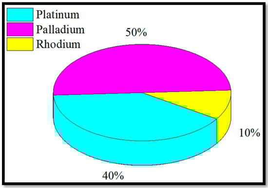
Figure 1.
Global utilization of PGM catalyst in catalytic converters up to 2025.
Catalysts containing rare-earth elements such as Mn, Ce, lanthanum (La), yttrium (Y), and samarium (Sm) have garnered significant attention in recent years. Mn-based catalysts can be synthesized using homogeneous precipitation or impregnation techniques, often with other metal oxides serving as supports, dopants, or promoters. The roles of various components in influencing catalytic activity and selectivity have been extensively studied over the past decades [8]. Mn exhibits excellent redox properties, particularly under low-temperature conditions. Mn oxides are categorized based on parameters such as specific surface area, dispersion, and oxidation states. For example, Mn active species are well dispersed on TiO2, enhancing catalytic performance. Further, Lewis acid sites on the synthesis of catalysts effectively adsorb hydrogen and also contribute to catalytic activity; a comparison of catalysts is shown in Table 2 [9].
Table 2.
Comparison of similar catalyst systems.
According to previous literature findings, PGMs have been widely utilized in diesel engine exhaust systems due to their proven ability to reduce emissions. These metals are typically coated on ceramic materials in a honeycomb structure, which serves as the standard approach for emission reduction. Previous research investigated the potential of rare-earth metals in emission control and demonstrated their superior performance across a wide range of operating temperatures compared to PGMs. This study is considered novel in its design and implementation, featuring the development of a new performance-enhanced mold resembling the conventional honeycomb structure. Moreover, this work utilizes the functionalities of two distinct rare-earth metal catalysts, Mn and Ce-Si-based mold, demonstrating superior emission reduction efficiency and enhanced thermal stability in engine applications. Its cost-effectiveness offers a significant advantage over traditional systems, making it a promising alternative for emission control technologies.
This comprehensive study presents a comparative emission analysis of Mn and Ce-Si synthesis catalyst-based molds for diesel engines at temperature ranges of 150–600 °C. The investigation focuses on the catalytic efficiency of these molds when utilizing base fuel and a DPB. Mn and Ce-Si catalyst-based molds are synthesized via impregnation and sol-gel processes, respectively. The synthesized molds are characterized both before and after exhaust gases pass, to evaluate their morphology using field emission scanning electron microscopy (FESEM)—Carl Zeiss, Oberkochen, Germany, functional groups using FTIR—PerkinElmer Inc., Waltham, MA, USA, a crystalline structure using XRD, PANalytical, Almelo, The Netherlands and surface textural properties using BET surface volume analysis, Micromeritics Instrument Corporation, Norcross, GA, USA. The correlation between SCR performance and operating conditions is assessed using an AVL444 gas analyzer—AVL List GmbH, Graz, Austria and smoke meter—AVL, Graz, Austria. The findings highlight their superior emission reduction efficiency and potential as sustainable alternatives to conventional emission control technologies, contributing to enhanced environmental sustainability.
2. Materials and Methods
2.1. Materials Utilized
Plastic oil, a high calorific value fuel, is purchased from M/s. Rathi Rubber Private Limited, Chennai, India. The chemical composition of plastic oil is dibenzylic propane-based hydrocarbons, making it closely resemble pure diesel. The chemicals like manganese dioxide (MnO2, 80%), sodium carbide (99.9%), aluminum chloride (AlCl3, 99%), cerium heptahydrate (99%), cerium (III) Chloride (99%) tetra ethyl ortho silicate (TEOS, 98%), propylene oxide (99%) and ethanol are purchased from SRL chemicals, Mumbai, India.
2.2. Preparation of Mn Synthesis Catalyst-Based Mold
The synthesis process for the Mn catalyst-based mold, illustrated in Figure 2, is adapted from previous studies [13,14,15] to ensure its suitability for combustion-related applications. The procedure begins with the preparation of reactants, where 18 g of MnCl2 and 34 g of CeCl3 were accurately measured, then the molar ratio of Mn:Ce ≈ 1:2 was obtained, and it was introduced into a reaction vessel. To this, 15 g of sodium carbide and AlCl2 were added. Ethanol, in a volume of 250 mL, was utilized as the reaction medium to facilitate homogenization of the mixture. The homogenized mixture underwent high-temperature processing in an autoclave at 450 °C, allowing it to interact under controlled thermal conditions. Then, the solution was subjected to an ultrasonication process for 3.45 h to enhance particle dispersion and promote uniform interactions. Subsequently, the ultrasonicated solution was agitated using a magnetic stirrer set at 250 rpm to ensure thorough mixing. Once the stirring process was completed, the solution was dried, and the Mn catalyst was obtained in its purified form. It underwent calcination in a temperature range of 450 to 550 °C and for 3–4 h. The catalyst was then shaped using a binder material, with plaster as supporting material to achieve the final mold structure.
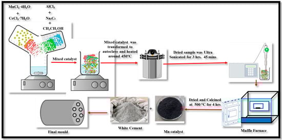
Figure 2.
Schematic representation of the synthesis procedure for Mn-based catalyst mold using the impregnation technique.
2.3. Preparation of Ce-Si Synthesis Catalyst-Based Mold
The synthesis process for the Ce-Si catalyst-based mold, illustrated in Figure 3, followed a systematic procedure utilizing the sol-gel method. Cerium (III) chloride (CeCl3) at the required quantity was dissolved in a mixture of water and ethanol, and its molar ratio was 1:1. This solution was stirred thoroughly to ensure the complete dissolution of CeCl3 and set aside for subsequent use. Simultaneously, tetraethyl orthosilicate was prepared by mixing tetraethyl orthosilicate (TEOS) with ethanol in a separate container. The mixture was stirred until a clear and homogeneous silica precursor solution was obtained [16].
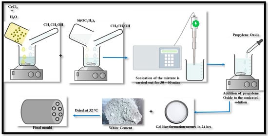
Figure 3.
Schematic representation of the sol-gel synthesis route for Ce-Si catalyst-based mold.
Next, the CeCl3 solution was gradually added to the Tetraethyl orthosilicate solution under continuous stirring to ensure proper mixing and homogeneity. The combined solution was then subjected to sonication, either using a sonication bath or a probe sonicator, for 30–60 min. This step promoted uniform dispersion of the components, which was essential for achieving a consistent precursor solution and pH of approximately 7–8. Then, propylene oxide was slowly introduced into the above-obtained solution while stirring gently.
This addition facilitated gel formation, transitioning the solution into a gel-like consistency at 24 h, at room temperature. Once the gel formed, white cement was incorporated into the mixture and stirred thoroughly to achieve uniform distribution, serving as the base material for the catalyst mold. Finally, the prepared mixture was poured into a suitable mold or container and allowed to cure under controlled conditions, such as 32 °C temperature or slightly elevated temperatures. This curing process solidified and stabilized the material, resulting in the formation of the Ce-Si catalyst mold at a calcination temperature range of 500 to 600 °C and a duration of 4 h. The sol-gel method employed in this synthesis integrated the advantageous properties of cerium and silica, yielding a robust and efficient catalytic material suitable for various applications. The specific images of the mold samples provide a visual representation of the structural features incorporated to increase efficiency for exhaust emission control measures. The examples shown utilized a honeycomb mold instead of the standard solid mold. The honeycomb structure would create more surface area and give improved bulk gas flow paths to increase catalytic contact and processing efficiency. The images also demonstrate that the length of the mold was extended for further initial improvement of the residence time of the exhaust gases in the catalyst zone as an additional mechanism for more pollutant conversion. The mold was constructed with five holes and was increased to seven holes. In theory, increasing the number of holes in the mold (perforation design) is likely to minimize exhaust emissions as well as increase gas diffusion and contact with the catalytic surfaces. In conclusion, the specific images illustrate deliberate engineering improvements in structural geometry, perforation design, and shapes that improve exhaust gas processing capability, allowing for lower emissions.
2.4. Characterization Studies
The characterization of the Mn and Ce-Si synthesis catalyst-based molds was performed both before and after exhaust gas passes through them. The samples were taken from the molds in different process configurations, which are designated as M1: Mn-based mold without exhaust gas passes in engine utilizing diesel fuel, M2: Ce-Si-based mold without exhaust gas passes in engine utilizing diesel fuel, M3: Mn-based mold without exhaust gas passes in engine utilizing DPB fuel, M4: Ce-Si-based mold without exhaust gas passes in engine utilizing DPB fuel, M5: Mn-based mold with exhaust gas passes in engine utilizing diesel fuel, M6: Ce-Si-based mold with exhaust gas passes in engine utilizing diesel fuel, M7: Mn-based mold with exhaust gas passes in engine utilizing DPB fuel, and M8: Ce-Si-based mold with exhaust gas passes in engine utilizing DPB fuel. FTIR spectroscopy was conducted using a Nicolet iS50 spectrometer, Thermo Fisher Scientific, Waltham, MA, USA. Prior to analysis, the samples were pre-treated in an air flow at 500 °C for 20 min and subsequently cooled to 100 °C under nitrogen (N2) flow. For NH3 adsorption studies, the samples were exposed to a 500 ppm NH3/N2 gas feed, and spectra were recorded every 10 min until NH3 adsorption reached saturation. The crystal structures of the catalyst base mold were identified using powder XRD with Cu Kα radiation. Intensity data were collected over a scattering angle range of 2θ = 5° to 80° at a scanning rate of 2°/min. Additionally, nitrogen adsorption and desorption isotherms were recorded at −195 °C using a Micrometrics analyzer, Micromeritics Instrument Corporation, Norcross, GA, USA. The specific surface area and pore size distribution were analyzed based on the BET method. SEM images were obtained using a Zeiss EVO50 microscope, Zeiss EVO50 microscope, Oberkochen, Germany. The scanning voltage and spot size were varied to achieve high-resolution images at different magnifications, enabling detailed observation of the catalyst’s surface morphology.
2.5. Experimental Setup
This investigation utilized a Kirloskar single-cylinder, four-stroke, IC engine rated at 5.2 kW. An eddy current dynamometer was employed to evaluate the engine’s performance under varying load conditions. The schematic layout of the research engine is depicted in Figure 4a, and the real-time engine setup is shown in Figure 4b,c. The detailed technical specifications of the engine are provided [10,17,18,19]. The engine was equipped with advanced instrumentation, including pressure transducers, thermocouples, mass flow sensors, and throttle position sensors, enabling a comprehensive analysis of combustion, performance, and emission characteristics. A data acquisition system (DAS) was integrated into the setup to record in-cylinder pressure profiles and facilitate real-time monitoring and control. Pressure sensors installed within the combustion chamber provided precise data on in-cylinder pressure dynamics, which were processed via the DAS [11,20,21]. Exhaust gas emissions were quantified using an AVL five-gas analyzer, enabling the measurement of critical emission parameters, including CO, carbon dioxide (CO2), NO, HC, and O2 concentrations engine measurement and specification details are shown in Table 3. A resistance thermometer was employed for precise monitoring of water temperature, while K-type thermocouples were strategically positioned at various locations within the cylinder chamber to capture localized thermal gradients. Additionally, the tailpipe emissions were analyzed to assess overall engine emission characteristics [22,23]. Six experimental trials were conducted to justify the impact of catalysts and fuel on exhaust gas emission analysis in the stationary diesel engine: T1: Engine utilizing diesel fuel; T2: Engine utilizing DPB fuel; T3: Engine utilizing diesel fuel and Mn-based mold; T4: Engine utilizing DPB fuel and Mn-based mold; T5: Engine utilizing diesel fuel and Ce-Si-based mold; and T6: Engine utilizing DPB fuel and Ce-Si-based mold.
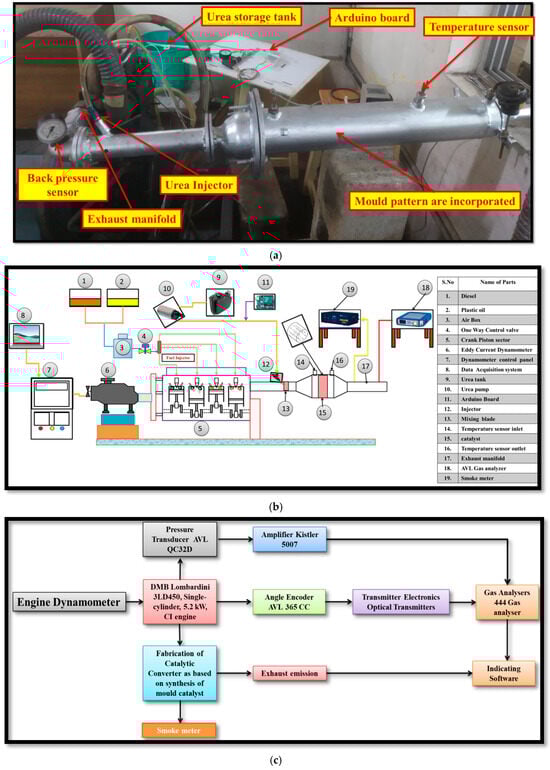
Figure 4.
(a) Photograph of the actual experimental diesel engine test setup. (b,c) Schematic layout of the experimental diesel engine test setup with integrated CC system.
Table 3.
Engine and mode specification.
3. Results and Discussion
3.1. FTIR Study
The Mn and Ce-Si-based molds under exhaust temperature conditions to activate the adsorption of exhaust species like NO, HC, CO, and smoke emissions, utilizing diesel and DPB fuels, with and without exhaust gas passing through them, are analyzed for stretching group behavior, and the obtained results are depicted in Figure 5. The comparison between Mn and Ce-Si synthesis catalysts based molds reveals that the Ce-Si-based mold is more effective in reducing NO emissions, as evidenced by FTIR characterization [11,24,25].
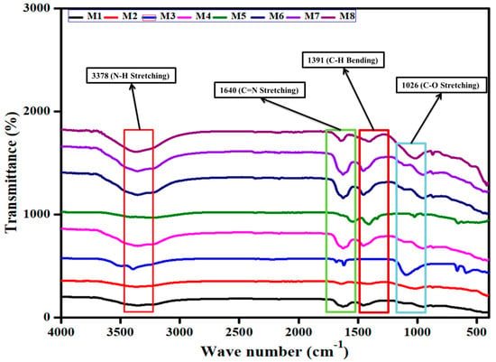
Figure 5.
FTIR spectra illustrating adsorption behavior of Mn and Ce-Si catalyst molds with and without exhaust gas passage.
In Figure 5, M1 shows wavenumbers at 3371, 1637, 1445, 1163, and 966 cm−1, while M2 exhibits wave numbers at 3344, 1643, 1423, 1031, and 878 cm−1. M3 displays wave numbers at 3396, 1688, 1626, 1092, and 472 cm−1; M4 shows wave numbers at 3361, 1634, 1455, 1109, and 958 cm−1. With the exhaust gas passes, M5 records wave numbers at 3399, 1533, 1424, 1035, and 665 cm−1. M6 shows 3372, 1637, 1447, 1126, and 962 cm−1. M7 under exhaust conditions produces wave numbers at 3377, 1637, 1472, 1121, and 948 cm−1, and M8 under exhaust conditions produces wave numbers at 3366, 1636, 1401, 1031, and 884 cm−1.
The FTIR spectrum for NO adsorption shows several weak bands for the Mn-based mold sample, including 3371, 1637, 1445, 1163, and 966 cm−1. The Ce-Si-based mold sample, in comparison, exhibits strong bands at 3344, 1643, 1423, 1031, and 878 cm−1, indicating the formation of N2O3. After exposure to NO, the Ce-Si-based mold sample shows a strong band at 3371 cm−1, with bands intensifying from 1688 to 1533 cm−1 as well. These observations suggest the presence of a cationic system in the Mn-based mold sample, whereas the Ce-Si-based mold sample demonstrates higher adsorption rates, particularly for bands at 1604 to 1026 cm−1, attributed to the ease of NO adsorption [26,27]. The Ce-Si-based mold sample also shows pronounced vibration features in the ranges of 1400 to 1385 cm−1, ascribed to nitrate species. Exhaust gas further facilitates NO reduction, with analysis indicating that NO was split into nitrogen and oxygen more effectively in the Ce-Si-based mold sample than in the Mn-based mold sample. Isotopic red shifts in the N-H stretching group are observed, with the Ce-Si-based mold sample showing higher adsorption of these species. In Ce-Si-based mold synthesis, catalysts disproportion NO emission in the range of 1640 to 1320 cm−1 [28].
Bands at 1251 to 1026 cm−1 are associated with nitrates, while bands between 1600 and 1250 cm−1 indicate the conversion of nitrates into nitro species. The Ce-Si-based mold sample demonstrates high IR intensities, reflecting enhanced NO adsorption and superior redox properties compared to the Mn-based mold sample. Furthermore, the interaction between compounds present in the molds contributes to improving NO adsorption on noble metal sites, consistent with the presence of large metallic Ce-Si particles [29]. Ce-Si-based mold exhibits higher NO adsorption capacity compared to the Mn mold. The nitrate and nitrite bands, particularly in the 1640 to 1600 cm−1 range, are significantly stronger for the Ce-Si-based mold sample. Additionally, the Ce-Si synthesis catalyst supports splitting the NO into nitrogen and oxide compared to the Mn synthesis catalyst, demonstrating its superiority in emission reduction applications. Then these results as wave number are expressed in cm−1 standard and SI consistent for spectral frequencies analysis as shown in Table 4.
Table 4.
FTIR ranges for both diesel and DPB.
3.2. XRD Study
The XRD analysis of the Mn- and Ce-Si-based molds was performed over the range of 2θ = 10–90°, and the resulting diffraction patterns are presented in Figure 6. Accentuated peaks pronounced at angles of 2θ = 28.55°, 33.58°, 47.79°, 56.47°, and 58.72° were indexable to the (111), (200), (220), (311), and (222) planes, respectively, confirming fluorite cubic phase structure for CeO2. Overall, the broadness and limited intensity of these peaks indicate a lower crystallinity, which is almost always extremely desirable in order to improve catalytic reactivity due to an increased amount of surface defects and active sites [30].
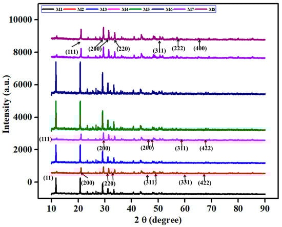
Figure 6.
X-ray diffraction patterns of Mn and Ce-Si catalyst-based molds showing crystal structure and phase analysis.
The slight shift in the diffraction peak found at 28.55° represents lattice distortion, which originates from the dopant Mn4+ ions in the CeO2 crystal, due to the smaller ionic radius of Mn (0.053 nm) compared to Ce (0.097 nm). This substitution effect can create oxygen vacancies and improve the redox characteristics of the catalyst. In the case of the Ce-Si-based mold, there appears to be an additional peak at 2θ = 37.33°, which corresponds to the MnO2 phase that potentially arises as a result of thermal treatment. The comparative analysis suggested that with regards to the Mn-based mold; it either has no peak or a weaker intensity than the Ce-Si-based mold peak at the MnO2 position suggesting that any excess Mn ions are not fully accommodated into the cerium oxide lattice and, that the formation of the separate MnO2 phases, are partially suppressed. Overall, the data suggested that the addition of modifying oxides can impede the crystallization of MnO2, which may also lead to increasing the dispersion and performance of active species during catalytic activity [31].
The diffraction peak at 2θ = 28.55° for the Mn-based mold sample shifts slightly toward higher angles, implying lattice contraction. Normally, Mo6+ ions have a radius of 0.059 nm, which is smaller than that of the Ce4+ ions, allowing Ce4+ ions to form larger crystals than Mo6+ ions. This difference in size means that Ce4+ ions can form larger crystals than Mo6+ ions. This difference in size also leads to different chemical and physical properties. The suppression of MnO2 crystallization by MO addition was beneficial to catalytic performance, as poor crystallization of MnO2 enhances its catalytic activity. As a result of these characterizations, the catalytic performance level has been increased due to the inhibition of Mo6+ in the catalyst for CeO2 synthesis. The results highlight the critical role of lattice modifications and controlled crystallization in optimizing catalyst functionality.
3.3. Morphology Analysis
SEM analysis is carried out for both Ce-Si and Mn-based mold samples with and without exhaust gas pass, and the obtained morphologies are shown in Figure 7. Upon exposure to exhaust gas, the morphology changes to an irregular form, suggesting structural degradation due to catalytic reactions. The Ce-Si-based mold sample initially presents a flower-like morphology, which evolves into an irregular structure when exposed to exhaust gas, reflecting substantial catalytic activity and interaction with exhaust compounds [32].
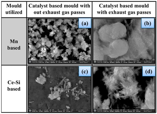
Figure 7.
Morphology of mold samples, (a)—Mn-based mold without exhaust gas passes, (b)—Mn-based mold with exhaust gas passes, (c)—Ce-based mold without exhaust gas passes, (d)—Ce-based mold with exhaust gas passes.
The Ce-Si-based mold sample exhibits highly porous, high adsorption capacity. These characteristics encourage a high-performance level for NO emission reduction. The increased surface area facilitates efficient adsorption and decomposition of NO into N2 and O2. In comparison, the Ce-Si-based mold sample demonstrates superior structural stability and catalytic efficiency, making it a more robust and effective choice for exhaust gas treatment applications than the Mn-based mold sample. Figure 7a represents the surface morphology of the Mn-based mold with no exhaust gas passes. This image could be described as being well-defined crystalline particles that appear relatively uniform in size and distribution. Figure 7b is a similar view of the Mn-based mold after exhaust gases have passed over the surface. This figure appears to have changed morphology altogether, as there now seem to be larger aggregated structures. These suggest that there may have been some level of sintering or at least structural changes due to the catalytic reactions. Figure 7c represents the Ce-Si-based catalyst mold prior to the exhaust gas passes, and its morphology appears as a flower-like and porous surface with dispersed particulate matter that assists in enhancing the number of available active sites for adsorption. Figure 7d displays a Ce-Si-based mold that has been subjected to exhaust gas passes; the morphology remains flower-like and appears altered slightly. This indicates that the structure has maintained its thermal and morphological stability while in operation. Each image has a clear scale bar that provides information about the level of magnification and allows for direct structural feature comparison for both Mn and Ce-Si-based catalyst molds under different conditions.
3.4. Surface Area Analysis
BET characterization represents the average pore structure, pore size, and pore volume of the targeted mold samples with exhaust gas pass. The obtained results are presented in Table 5. The Ce-Si-based mold sample exhibits a higher pore volume, which enhances the dispersion of the Ce-Si compound on the catalyst surface. Comparatively, the Ce-Si-based mold sample exhibits better surface area, encouraging better adsorption capacities. Thus, it supports emission reduction while passing exhaust gas through it, due to its pore structure, impregnation drying, and calcination steps [33]. BET results indicate that the surface area increases compared to the Mn-based mold sample [34], due to its higher degree of pore filling while exhaust gas passes through it.
Table 5.
BET study comparing Ce-Si-based and Mn-based samples.
The nitrogen adsorption–desorption isotherms and BJH pore size distribution plots for the Mn- and Ce-Si templates. The Ce-Si catalyst exhibits a typical Type IV isotherm featuring an H3-type hysteresis loop, indicating mesopores made up of slit-like pores produced by plate-like particles. The pore size distribution curve shows a predominant peak in the 4 and 6 nm range, confirming their mesoporosity. The Mn-based template shows a much narrower distribution with a peak at about 3 nm, indicating a smaller mean pore size. The Ce-Si template has a very broad range of pore sizes and a significantly higher mesoporosity, which presumably permits better diffusion of the reactants and enhances both NOx adsorption and dissociation, consistent with the observed greater emissions reduction efficiencies during the engine tests as shown in Figure 8.
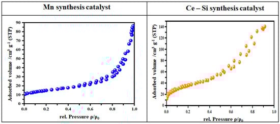
Figure 8.
Surface area analysis of Mn and Ce-Si catalyst-based molds showing crystal structure and phase analysis.
3.5. Emission Analysis
3.5.1. Exhaust Emissions
Exhaust emissions were investigated in diesel and DPB fuels utilized engines with Mn and Ce-Si-based molds under minimum and maximum load conditions, and the obtained readings are depicted in Figure 9. The Mn- and Ce-Si-based molds were evaluated for their effectiveness in reducing NO exhaust emissions. The Mn-based mold shows a lower pore structure and volume than the Ce-Si-based mold, which exhibits a higher pore structure and adsorption capacity. The Ce-Si-based mold is highly efficient for NO emission reduction [35]. Compared to trial T1, NO emissions are reduced by 66.67%, 69.29%, 70.17%, and 80.70% for trials T3 to T6, respectively, under minimum load conditions. The same is further reduced by 73.18%, 74.09%, 74.54%, and 80%, for trials T3 to T6 when compared with T1 under maximum load conditions.
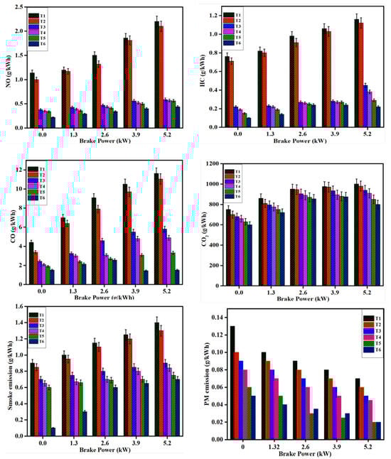
Figure 9.
Comparative exhaust emission analysis (NO, HC, CO, smoke, and PM) for different catalyst configurations under minimum and maximum loads.
Under minimum load conditions, HC emissions demonstrate significant reductions when compared to trial T1. Specifically, reductions of 71.05%, 75%, 80.26% and 86.84% were observed for trials T3, T4, T5, and T6, respectively. Under maximum load conditions, HC emissions were further reduced by 61.20%, 67.04%, 75%, and 81% for trials T3, T4, T5, and T6 compared to T1. For CO emissions under maximum load conditions, reductions of 44.67%, 52.60%, 56.68% and 65.75% were recorded for trials T3, T4, T5, and T6, respectively. Under maximum load conditions, these reductions increased to 50%, 57.91%, 71.48% and 87% for trials T3 to T6 in comparison to T1.
CO2 emissions also exhibited a notable decrease. Under minimum load conditions, reductions of 9.33%, 12%, 16%, and 20% was observed for trials T3, T4, T5 and T6, respectively, relative to T1. Similarly, under maximum load conditions, CO2 emissions were reduced by 6%, 9%, 15%, and 20% for trials T3 and T6 compared to T1.
Smoke emissions followed a similar trend. Under maximum load conditions, reductions of 22.22%, 27.77%, 33.33% and 88.88% was achieved for trials T3, T4, T5, and T6, respectively, relative to T1. Under maximum load conditions, the reduction was 35.71%, 40%, 46.42% and 50% for trials T3 to T6 when compared with T1.
PM emissions followed a similar trend. Under maximum load conditions, reductions of 16.66%, 27.77%, 50.50% and 75.00% was achieved for trials T3, T4, T5, and T6, respectively, relative to T1. Under maximum load conditions, the reduction was 35.71%, 40%, 46.42% and 50% for trials T3 to T6 when compared with T1.
The experimental results thoroughly highlight the relative performance of the Mn and Ce-Si synthesis catalyst-based molds over the maximum engine load conditions. The FTIR spectra show that the Ce-Si mold has substantially more intense adsorption bands associated to the nitrate and nitrite species, than the Mn-based mold, suggesting better NO adsorption and stronger redox behavior; the shift and intensity of these vibrational bands showed that the Ce-Si catalyst has a more efficient means of NO decomposition into nitrogen and oxygen, therefore directly assisting with NO abatement.
The XRD analyses showed that the Ce-Si mold has broader and less intense diffraction peaks compared to the Mn-based mold, suggesting better active species dispersion and more amorphous material, which leads to high catalytic activity and thermal stability. The apparent suppression of unwanted crystallization phases in the case of the Mn mold suggests that the Ce-Si system maintains structural integrity for the entire operating temperature range tested.
SEM micrographs show considerable differences in morphology between the two catalysts. The Ce-Si mold has a well-developed porous structure with high surface area and homogeneous particle dispersion and was determined to be durable under CC operation even after the exhaust gas had been flushed through. Although the Mn mold demonstrates a considerable reduction in structure, it remains to be seen if its degraded structure will hinder the performance of the Mn catalyst in refractory conditions typical of high-temperature exhaust.
Micrographs of the BET surface area and pore analysis confirm that the Ce-Si mold shows the best performance. The Mn mold has a slightly greater initial specific surface area, but the Ce-Si mold has a higher pore volume and more appropriate distribution of pore sizes for optimal gas diffusion, which significantly aids the access of reactants to the active sites. The observed difference in structure contributes to the trends seen in emissions reductions.
The analysis of engine exhaust emissions under both minimum and maximum loads shows that the SCR system combined with the Ce-Si mold will reduce NO, HC, CO, and smoke emissions significantly in both minimum and maximum loads with the DPB. Notably, NO emissions were reduced by as much as 80.70% under minimum load and 80% under maximum load, while HC emissions demonstrated reductions over 80% and CO emissions demonstrated reductions over 65%. The reforms in emissions validate that the Ce-Si catalyst helps not only to increase the effectiveness of pollutant conversion efficiencies, but also improves combustion quality.
Overall, the findings have been logically linked to the systematic relation of the physicochemical properties of the Ce-Si synthesis catalyst; i.e., its better oxygen storage capacity (OSC). The Ce-Si mold has higher redox behavior because of the reversible Ce3+/Ce4+ oxidation states that allow dynamic oxygen storage and release. This characteristic is directly related to the efficient conversion of NO into N2 and O2 during CC via continued redox cycles. In addition, the BET and SEM data indicate that the Ce-Si catalyst has a higher surface area and more pore volume for gas diffusion/availability to reactants at active sites. The XRD patterns show that the crystalline phase is well dispersed, which also supports that the Ce-Si matrix holds its stability and its accessibility to active sites when it comes to the exposed nature of exhaust gases. The FTIR data also indicate better bands for the adsorption of nitrates/nitrites, which demonstrates the Ce-Si material’s better OSC, as well as having a better adsorption capacity. All of the physicochemical properties contribute directly to the favorable NO reduction efficiency (up to 80.70%) and overall emissions reduction, which supports that both the intrinsic oxygen storage and redox capabilities of the catalyst give way to its catalytic efficiencies.
In summary, unique surface chemistry, crystalline stability, and favorable morphology allow the Ce-Si synthesis catalyst to deliver repeatable, effective emission control performance throughout a wide range of operating temperatures. Overall, these data validate the general performance of the Ce-Si catalyst, demonstrating that it can be a feasible and stable sustainable substitute for conventional pollutant emission control materials, improving the overall research goal of achieving the necessary environmental goals for stricter emissions standards and environmental sustainability.
PM emissions control solutions in diesel engines can be achieved through design, treatment, optimization, and upgrades. DPFs are used because of the various performance-based parameters they provide to accomplish complete oxidation of soot PM deposits that are contained within the diesel exhaust stream. DPFs are constructed from porous ceramic materials that hold the generated soot in place while allowing sufficient oxidation of the soot PM to occur. As with DPFs, CC and SCR units will reduce PM emissions by promoting the complete burn of unburned hydrocarbons to improve overall combustion quality. The use of rare-earth metal catalysts, such as the Ce-Si synthesis catalysts developed in this research, can promote PM emissions reductions based on their ability to store oxygen and have reversible redox states of Ce3+ and Ce4+. This new redox-based mechanism stores oxygen, which will provide active oxygen species to oxidize soot PM emissions into harmless and less harmful gases. The additional high surface area and porous structure used in the Ce-Si catalyst mold will retain appropriate gas diffusion to maximize contact between the exhaust fuel and active sites in the mold face, which will promote more consistent PM conversion during the exhaust cycle that can occur over temperature ranges of 150 °C to 600 °C.
Another important avenue for reducing PM from the source is improving combustion quality. This can be accomplished by blending diesel fuel with oxygenated fuels such as waste plastic oil, which helps increase atomization, provides better air–fuel mixing, and reduces zones of incomplete combustion which are where soot nuclei are generally found. Furthermore, optimizing operating conditions of the engine—by using the proper air–fuel ratio, using high-pressure multiphase injection, and retarding injection timing slightly—can help to reduce the formation of locally rich pockets of fuel where PM precursors originate. Also, EGR can be applied to reduce peak cylinder temperature to essentially suppress thermal cracking of heavier HC, leading to soot formation. Additionally, using catalytic fuel additives, such as cerium oxide nanoparticles, could help act in-cylinder to catalyze better completion of fuel oxidation which will help eliminate or reduce the carbon residue that leads to PM formation.
Together, a Ce-Si synthesis catalyst mold, a diesel–DPB and SCR treatment, as shown in this study, provide a strong and effective strategy for decreasing PM emissions. The experimental results make evident that the combined attributes of high redox activity, large surface area, enhanced pore volume, and thermal stability found in the Ce-Si catalyst contribute directly to reducing PM with proceeding reductions of other regulated emissions to support the compliance with tighter emission regulations and advance environmental sustainability, as shown in Table 6.
Table 6.
Comparison of similar catalysts when reducing exhaust emissions.
3.5.2. NH3 Conversion Efficiency
The reaction of NH3 with Mn and Ce-Si-based mold in examining NO conversion efficiency was investigated with the SCR technique, and the obtained results are depicted in Figure 10. The molds are utilized to perform efficiently under maximum load conditions. The exhaust manifold system has recently evolved to operate across a wider temperature range, leading to increased demand for Ce-Si-based molds, which are well-suited for such conditions. However, achieving high activity in the lower temperature range remains a challenge [36]. For instance, Mn-based mold, derived from salts, can react with SO2 present in exhaust gases to form MnSO4, which can poison the catalyst’s active sites. This issue contributes to the ongoing problem of catalyst deterioration. Moreover, the Mn-based mold is limited to a narrow temperature range, making it unsuitable for applications requiring versatility across varying temperatures. This limitation underscores the superiority of Ce-Si synthesized catalysts, which deliver outstanding performance and stability in challenging environments, particularly those involving high urea content treatments and elevated temperatures, where both efficiency and reliability are crucial. The Ce-Si-based mold maintains consistent activity across a broad temperature range of 150 to 600 °C [12,37,38]. At maximum load conditions, the Ce-Si catalyst mold achieves an 80% higher NO conversion efficiency compared to the Mn-based catalyst mold. Additionally, urea treatment significantly enhances the effectiveness of the Ce-Si mold, making it highly efficient in reducing NO emissions.
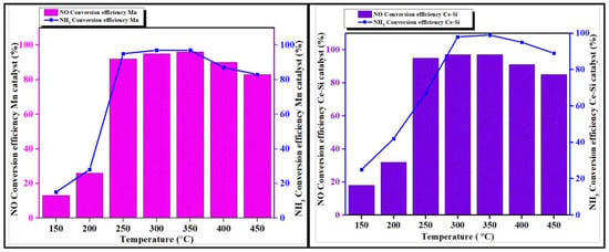
Figure 10.
NO and NH3 conversion efficiency of Mn and Ce-Si catalyst molds under SCR process.
3.6. Catalytic Mechanism
The Ce-Si catalyst tested in this work acts as a fairly efficient thermal catalyst for diesel engine exhaust emissions such as NO, HC, and CO. Cerium catalysts are well known to be great with oxygen storage and reversible redox properties Ce3+/Ce4+ that can assist oxidation and reduction reactions at normal exhaust temperatures [39], as shown in Figure 11.
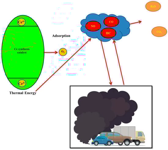
Figure 11.
Illustrated thermal catalyst mechanism for Ce-Si and Mn synthesis catalyst.
The dominant catalytic mechanism is considered thermal as opposed to relying on some sort of external irradiation. While the engine was operational, the hot exhaust gas induced redox cycling of the Ce3+ and Ce4+ species, resulting in the continuous supply of active oxygen [40]. This chemical mechanism facilitates CO and HC oxidation to CO2 and H2O, while also promoting the reduction of NO to N2. The sol-gel synthesis method used ensures that cerium oxide is uniformly dispersed throughout the silica matrix and prevents sintering at high temperatures, increasing the catalyst’s long-term thermal stability [41].
The catalytic efficiencies were tested under real diesel exhaust conditions with no UV light supplied. There was no external light source or photo catalytic enhancement during the test. Therefore, any references to photo catalytic activity are only pertaining to the general potential of the Ce-Si materials and do not describe the operation conditions tested in this situation [42,43,44].
A comparative study of the structural and surface characteristics defining this thermal catalytic activity was carried out by FTIR, XRD, SEM, and BET surface pore volume analysis. The findings from the FTIR spectra indicated the presence of various functional groups and adsorbed species, which also confirmed robust O2 storage and redox activity [45]. The findings from the XRD spectra determined that the processed CeO2 material had stable crystalline phases producing good solid-state dispersion, and the amorphous SiO2 support material inhibited material agglomeration while maintaining a high surface area. The SEM images indicated that the same pattern of well-distributed, stable particle morphology and availability of accessible active sites.
BET surface area measurements determined that the Ce-Si mold retained a high surface area capacity with even repeated thermal cycling achieving consistent catalytic performance at high exhaust temperatures, whereas the Mn-based mold achieved a performance with commendable thermal redox activity at low-to-moderate temperatures by forming Mn–O and Mn–OH bonds and also through the activation of the NO species, but The surface area and pore structure appeared to be less stable due to sintering upon prolonged thermal exposure, resulting in a gradual decrease in adsorption capacity and the availability of active sites [46,47].
In summary and conclusion, the Ce-Si catalyst has very good thermal stability and redox activity without an active source of external light, which is very advantageous for diesel exhaust after treatment in continuous operation applications.
3.7. Cross-Sectional Area of Synthesis Catalyst
The cross-sectional area of the Mn synthesis catalyst is also laid out to maintain adequate surface accessibility to reactant gases. The Mn-based mold entails a porous structural form that is considered a somewhat designed porous matrix that was produced more as simply impregnation processes with fairly high surface area by BET characterization with a privileged porous structure, so that all the pores were interconnected so to ensure maximum surface or volume for NO adsorption and activation and with respect to the strong redox properties of Mn, especially at lower exhaust temperatures. In distributing the Mn active sites across the cross-section of the mold, there was enough distribution of active sites that impacted oxidation of CO and HC species in parallel, where the Lewis acid sites in the catalyst played a role in some of the hydrogen adsorption and reaction pathway possibilities after the initial ideal adsorption of NO. However, compared to the Ce-Si catalyst, the Mn-based mold appeared to have lower pore volume and was somewhat less thermally stable, and the range of activity was at fairly higher temperature ranges. Overall, the optimized cross-sectional area of the Mn-based mold has contributed to the important catalytic interaction work and has resulted in demonstrating observable reductions in NO and HC emissions at minimum to maximum load conditions, as shown in Figure 12a,b.
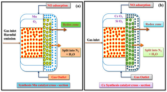
Figure 12.
Illustrated cross-sectional area of catalyst (a) Mn synthesis catalyst and (b) Ce-Si synthesis catalyst.
4. Expanded Conclusions
This study systematically investigated and compared the emission control efficiency of Mn and Ce-Si synthesis catalyst-based molds incorporated into a diesel engine with conventional diesel fuel as well as a DPB. The Ce-Si-based mold was shown to consistently outperform the Mn-based mold using advanced synthesis, characterization of both the catalyst and molds, and the engine exhaust emissions evaluations using minimum to maximum load conditions for both fuels.
Findings importantly illustrate that the Ce-Si catalyst mold provided excellent NO reduction efficiencies with a minimum load of 80.70% and 80% of the maximum load with DPB fuel. The catalyst mold had great emission reductions for HC (up to 86.84%), CO (up to 87%), CO2 (up to 20%), and smoke opacity (up to 88.88%). This means that the Ce-Si-based mold exhibited great NO reductions via the CC reaction pathway and dramatically reduces and rigs conserve unburnt hydrocarbons and carbon emissions due to its favorable redox properties, high surface area, and higher thermal stability.
The findings from the morphology and pore structure tests showed that the Ce-Si mold maintained structural integrity and surface area after running exhaust gases, while the Mn-based mold did not manage to do so due to loss of porosity and activity at exaggerated temperature conditions.
Additionally, the Ce3+/Ce4+ system has a greater storage capacity for oxygen, thereby making reactions for oxidation and adsorption more sustainably maintainable, and this captures reduced exhaust emissions. Furthermore, the Ce-Si molds’ range of performance (150–600 °C) is very good relative to the real-world conditions with diesel as its progressively increasing-temperature conditions. On top of that (and overall), aside from experimental results supporting the viability of the Ce-Si catalysts to SCR technology with plastic-oil-diesel blends with value-add consideration to circular economy and waste plastics value-added to the goal of reducing virgin fossil-fuel to meet Bharat Stage VI emissions standards limits.
5. Final Conclusions
In conclusion, this research has clearly demonstrated that the Ce-Si synthesis catalyst-based molds, used in combination with CC systems and plastic oils, represent a significantly effective, sustainable, and cheap means of reducing harmful emissions from diesel engines. The use of advanced rare-earth catalysts enables clean combustion, reduced greenhouse gases, and a considerable contribution toward the Sustainable Development Goals (SDGs 7, 11, and 13). Future work would incorporate metal–organic frameworks (MOFs) or other next-generation catalyst structures to enhance emissions control and increase the operational durability of such systems in the widest variety of real-world testing conditions. In conclusion, the acquired Ce-Si-based catalyst displayed favorable structural and catalytic properties for reducing exhaust emissions. However, it should be noted that the lifetime and durability of the catalyst under continuous engine operation were not evaluated in this study. For practical applicability, prolonged performance tests, including thermal aging, cyclic regeneration, and long-duration operation.
Author Contributions
Methodology, P.S., K.G., M.S., A.T. and B.D.; Validation, P.S., J.K.P., R.K., M.S. and B.D.; Formal analysis, R.K., M.S., A.T. and B.D.; Investigation, P.S., K.G., J.K.P. and B.D.; Data curation, J.K.P. and R.K.; Writing—draft, P.S., K.G., M.S., A.T. and B.D.; Writing—review & editing, P.S., K.G., M.S. and A.T. All authors have read and agreed to the published version of the manuscript.
Funding
This research received no external funding.
Data Availability Statement
The original contributions presented in the study are included in the article, further inquiries can be directed to the corresponding authors.
Acknowledgments
This work was partially funded by the Centre for Sustainable Materials and Surface Metamorphosis, Chennai Institute of Technology, India, through funding number CIT/CSMSM/2024/RP/005. Also, the authors thank the Thermal Laboratory (Mechanical Department) and SRM Central Instrumentation Facility (SCIF), SRM Institute of Science and Technology, Kattankulathur, Chengalpattu, Tamil Nadu, for assisting us in carrying out experimental studies and characterization studies.
Conflicts of Interest
The authors declare that they have no known competing financial interests or personal relationships that could have appeared to influence the work reported in this paper.
Nomenclature
| AlCl3 | Aluminum Chloride |
| BET | Brunauer–Emmett–Teller |
| CC | Catalytic Converters |
| CeO2 | Cerium Oxide |
| Ce-Si | Ceriumsilica |
| CO | Carbon Monoxide |
| CO2 | Carbon Dioxide |
| CeCl3 | Cerium (III) Chloride |
| DAS | Data Acquisition Systems |
| DOC | Diesel Oxidation Catalyst |
| DPB | Diesel–Plastic Blend |
| DPF | Diesel Particulate Filter |
| EGR | Exhaust Gas Recirculation |
| FTIR | Fourier Transform Infrared Spectroscopy |
| HC | Hydrocarbon |
| HDVs | Heavy-Duty Vehicles |
| H2O | Water |
| IC | Internal Combustion |
| La | Lanthanum |
| LDVs | Light-Duty Vehicles |
| LNT | Lean NOx Traps |
| Mn | Manganese |
| N2 | Nitrogen |
| NH3 | Ammonia |
| NO | Nitrogen Oxide |
| NSCR | Non-Selective Catalytic Reduction |
| OH | Hydroxyl Radicals |
| OSC | Oxygen Storage Capacity |
| O2 | Superoxide Ions |
| PGMs | Platinum Group Metals |
| PM | Particulate Matter |
| ROS | Reactive Oxygen Species |
| SCR | Selective Catalytic Reduction |
| SEM | Scanning Electron Microscope |
| SiO2 | Silicon Dioxide |
| Sm | Samarium |
| XRD | X-ray Diffraction |
| TEOS | Tetra Ethyl Ortho Silicate |
| Y | Yttrium |
References
- Kaimal, V.K.; Vijayabalan, P. A study on synthesis of energy fuel from waste plastic and assessment of its potential as an alternative fuel for diesel engines. Waste Manag. 2016, 51, 91–96. [Google Scholar] [CrossRef] [PubMed]
- Kaewbuddee, C.; Sukjit, E.; Srisertpol, J.; Maithomklang, S.; Wathakit, K.; Klinkaew, N.; Liplap, P.; Arjharn, W. Evaluation of waste plastic oil-biodiesel blends as alternative fuels for diesel engines. Energies 2020, 13, 2823. [Google Scholar] [CrossRef]
- Mohan, R.K.; Sarojini, J.; Rajak, U.; Verma, T.N.; Ağbulut, Ü. Alternative fuel production from waste plastics and their usability in light-duty diesel engine: Combustion, energy, and environmental analysis. Energy 2023, 265, 126140. [Google Scholar]
- Sundar, S.P.; Palanimuthu, V.; Sathyamurthy, R.; Hemalatha, D.; Kumar, R.S.; Bharathwaaj, R.; Vasanthaseelan, S.; Chamkha, A. Feasibility study of neat plastic oil with TiO2 nanoadditive as an alternative fuel in internal combustion engine. J. Therm. Anal. Calorim. 2022, 147, 2567–2578. [Google Scholar] [CrossRef]
- Raj, B.K.; Jyothi, Y.; Kanasani, P.; Gangadhar, D.S. The best suitable alternative to diesel in a compression ignition engine between waste plastic oil and waste tire oil blends with diesel. Energy Sources Part A Recover. Util. Environ. Eff. 2020, 42, 2731–2741. [Google Scholar] [CrossRef]
- Sunaryo, S.; Sesotyo, P.A.; Saputra, E.; Sasmito, A.P. Performance and fuel consumption of diesel engine fueled by diesel fuel and waste plastic oil blends: An experimental investigation. Automot. Exp. 2021, 4, 20–26. [Google Scholar] [CrossRef]
- Das, A.K.; Hansdah, D.; Mohapatra, A.K.; Panda, A.K. Energy, exergy and emission analysis on a DI single cylinder diesel engine using pyrolytic waste plastic oil diesel blend. J. Energy Inst. 2020, 93, 1624–1633. [Google Scholar] [CrossRef]
- Arjharn, W.; Liplap, P.; Maithomklang, S.; Thammakul, K.; Chuepeng, S.; Sukjit, E. Distilled waste plastic oil as fuel for a diesel engine: Fuel production, combustion characteristics, and exhaust gas emissions. ACS Omega 2022, 7, 9720–9729. [Google Scholar] [CrossRef]
- Ramesha, D.K.; Kumara, G.P.; Lalsaheb; Mohammed, A.V.T.; Mohammad, H.A.; Kasma, M.A. An experimental study on usage of plastic oil and B20 algae biodiesel blend as substitute fuel to diesel engine. Environ. Sci. Pollut. Res. 2016, 23, 9432–9439. [Google Scholar] [CrossRef]
- Liu, Y.; Tan, J. Experimental study on solid SCR technology to reduce NOx emissions from diesel engines. IEEE Access 2020, 8, 151106–151115. [Google Scholar] [CrossRef]
- Zhang, Z.; Ye, J.; Tan, D.; Feng, Z.; Luo, J.; Tan, Y.; Huang, Y. The effects of Fe2O3 based DOC and SCR catalyst on the combustion and emission characteristics of a diesel engine fueled with biodiesel. Fuel 2021, 290, 120039. [Google Scholar] [CrossRef]
- Tan, L.; Guo, Y.; Liu, Z.; Feng, P.; Li, Z. An investigation on the catalytic characteristic of NO reduction in SCR systems. J. Taiwan Inst. Chem. Eng. 2019, 99, 53–59. [Google Scholar] [CrossRef]
- Kumar, A.; Pali, H.S.; Kumar, M. Evaluation of waste plastic and waste cooking oil as a potential alternative fuel in diesel engine. Next Energy 2024, 5, 100181. [Google Scholar] [CrossRef]
- Faisal, F.; Rasul, M.; Jahirul, M.; Chowdhury, A.A. Waste plastics pyrolytic oil is a source of diesel fuel: A recent review on diesel engine performance, emissions, and combustion characteristics. Sci. Total Environ. 2023, 886, 163756. [Google Scholar] [CrossRef]
- Damodharan, D.; Sathiyagnanam, A.; Rana, D.; Saravanan, S.; Kumar, B.R.; Sethuramasamyraja, B. Effective utilization of waste plastic oil in a direct injection diesel engine using high carbon alcohols as oxygenated additives for cleaner emissions. Energy Convers. Manag. 2018, 166, 81–97. [Google Scholar] [CrossRef]
- Güngör, C.; Serin, H.; Özcanlı, M.; Serin, S.; Aydın, K. Engine performance and emission characteristics of plastic oil produced from waste polyethylene and its blends with diesel fuel. Int. J. Green Energy 2015, 12, 98–105. [Google Scholar] [CrossRef]
- Bhargavi, M.; Kumar, T.V.; Shaik, R.A.A.; Kanna, S.K.; Padmanabhan, S. Effective utilization and optimization of waste plastic oil with ethanol additive in diesel engine using full factorial design. Mater. Today Proc. 2022, 52, 930–936. [Google Scholar] [CrossRef]
- Latha, H.S.; Prakash, K.V.; Veerangouda, M.; Maski, D.; Ramappa, K.T. A review on SCR system for NOx reduction in diesel engine. Int. J. Curr. Microbiol. Appl. Sci. 2019, 8, 1553–1559. [Google Scholar]
- Resitoglu, I.A.; Altinisik, K.; Keskin, A.; Ocakoglu, K. The effects of Fe2O3 based DOC and SCR catalyst on the exhaust emissions of diesel engines. Fuel 2020, 262, 116501. [Google Scholar] [CrossRef]
- Wardana, M.K.A.; Lim, O. Review of improving the NOx conversion efficiency in various diesel engines fitted with SCR system technology. Catalysts 2022, 13, 67. [Google Scholar] [CrossRef]
- Keskin, A.; Yaşar, A.; Candemir, O.C.; Özarslan, H. Influence of transition metal based SCR catalyst on the NOx emissions of diesel engine at low exhaust gas temperatures. Fuel 2020, 273, 117785. [Google Scholar] [CrossRef]
- Zhu, Y.; Xia, C.; Shreka, M.; Wang, Z.; Yuan, L.; Zhou, S.; Feng, Y.; Hou, Q.; Ahmed, S.A. Combustion and emission characteristics for a marine low-speed diesel engine with high-pressure SCR system. Environ. Sci. Pollut. Res. 2020, 27, 12851–12865. [Google Scholar] [CrossRef]
- Nie, X.; Bi, Y.; Liu, S.; Shen, L.; Wan, M. Impacts of different exhaust thermal management methods on diesel engine and SCR performance at different altitude levels. Fuel 2022, 324, 124747. [Google Scholar] [CrossRef]
- Pietikäinen, M.; Väliheikki, A.; Oravisjärvi, K.; Kolli, T.; Huuhtanen, M.; Niemi, S.; Virtanen, S.; Karhu, T.; Keiski, R.L. Particle and NOx emissions of a non-road diesel engine with an SCR unit: The effect of fuel. Renew. Energy 2015, 77, 377–385. [Google Scholar] [CrossRef]
- Lei, Y.; Qin, C.; Qiu, T.; Yue, G.; Ding, M. NOx emission removal from a parallel diesel engine group by scr system based on distributed control technology. Environ. Sci. Technol. 2021, 55, 6352–6362. [Google Scholar] [CrossRef]
- Loganathan, C.S. Emission reduction from a diesel engine fueled by cerium oxide nano-additives using SCR with different metal oxides coated catalytic converter. J. Eng. Sci. Technol. 2015, 10, 1404–1421. [Google Scholar]
- Zhang, Y.; Xia, C.; Liu, D.; Zhu, Y.; Feng, Y. Experimental investigation of the high-pressure SCR reactor impact on a marine two-stroke diesel engine. Fuel 2023, 335, 127064. [Google Scholar] [CrossRef]
- Feng, S.; Li, Z.; Shen, B.; Yuan, P.; Ma, J.; Wang, Z.; Kong, W. An overview of the deactivation mechanism and modification methods of the SCR catalysts for denitration from marine engine exhaust. J. Environ. Manag. 2022, 317, 115457. [Google Scholar] [CrossRef]
- Kim, H.J.; Jo, S.; Kwon, S.; Lee, J.-T.; Park, S. NOx emission analysis according to after-treatment devices (SCR, LNT + SCR, SDPF), and control strategies in Euro-6 light-duty diesel vehicles. Fuel 2022, 310, 122297. [Google Scholar] [CrossRef]
- Wang, T.J. Effects of insulation on exhaust temperature and subsequent SCR efficiency of a heavy-duty diesel engine. J. Mech. Sci. Technol. 2019, 33, 923–929. [Google Scholar] [CrossRef]
- Chen, Z.; Liu, Q.; Liu, H.; Wang, T. Recent advances in SCR systems of heavy-duty diesel vehicles—Low-temperature NOx reduction technology and combination of SCR with remote OBD. Atmosphere 2024, 15, 997. [Google Scholar] [CrossRef]
- Tempelman, C.; el Arkoubi, B.; Spaan, J.; Slevani, R.; Degirmenci, V. Decomposition of heavy diesel SCR urea fluid adsorbed in Cu/HZSM-5 SCR catalysts studied by FTIR spectroscopy at ambient conditions. Reactions 2022, 3, 576–588. [Google Scholar] [CrossRef]
- Liu, K.; Pei, Z.; Deng, B.; Yang, J.; Li, Y. Experimental study on transient emissions characteristics of a heavy duty natural gas engine under world harmonized transient cycle. Case Stud. Therm. Eng. 2022, 38, 102377. [Google Scholar] [CrossRef]
- Irshad, M.A.; Nawaz, R.; Ur Rehman, M.Z.; Adrees, M.; Rizwan, M.; Ali, S.; Ahmad, S.; Tasleem, S. Synthesis, char-acterization and advanced sustainable applications of titanium dioxide nanoparticles: A review. Ecotoxicol. Environ. Saf. 2021, 212, 111978. [Google Scholar]
- Liu, G.; Zhang, H.; Li, Y.; Wang, P.; Zhan, S. Selective catalytic reduction of NOx with NH3 over copper-based catalysts: Recent advances and future prospects. EES Catal. 2024, 2, 231–252. [Google Scholar]
- Lisi, L.; Cimino, S. Poisoning of SCR catalysts by alkali and alkaline earth metals. Catalysts 2020, 10, 1475. [Google Scholar] [CrossRef]
- Xu, J.; Yu, H.; Zhang, C.; Guo, F.; Xie, J. Development of cerium-based catalysts for selective catalytic reduction of nitrogen oxides: A review. New J. Chem. 2019, 43, 3996–4007. [Google Scholar] [CrossRef]
- Tan, L.; Feng, P.; Yang, S.; Guo, Y.; Liu, S.; Li, Z. CFD studies on effects of SCR mixers on the performance of urea conversion and mixing of the reducing agent. Chem. Eng. Process.-Process Intensif. 2018, 123, 82–88. [Google Scholar] [CrossRef]
- Zhang, Z.; Zhao, Z.; Tan, D.; Zhang, B.; Lu, K.; Ye, Y.; Mao, C. Experimental study of ammonia storage characteristics of selective catalytic reduction for diesel engine based on Cu-based catalysts. Process. Saf. Environ. Prot. 2024, 190, 368–380. [Google Scholar] [CrossRef]
- Qing, M.; Su, S.; Qian, K.; Liu, L.; Yin, Z.; Hu, S.; Wang, Y.; Xiang, J. Insight into the catalytic performance and NH3 adsorption under high concentration of CO2 and/or H2O conditions on selective catalytic reduction of NO by NH3 over V2O5-WO3/TiO2 catalyst. Fuel 2021, 286, 119478. [Google Scholar] [CrossRef]
- Duan, L.; Hsieh, Y.-L.; Lin, S.-L.; Mansor, W.N.W.; Bin Mansor, M.I.A.; Lee, H.; Huang, C.-E.; Chao, H.-R.; Song, M.; Song, M. Unignorable emissions and potential health effects of unregulated pollutants from nonroad engines using greener fuels—A review. Aerosol Air Qual. Res. 2024, 24, 240074. [Google Scholar] [CrossRef]
- Gevers, L.E.; Enakonda, L.R.; Shahid, A.; Ould-Chikh, S.; Silva, C.I.Q.; Paalanen, P.P.; Aguilar-Tapia, A.; Hazemann, J.-L.; Hedhili, M.N.; Wen, F.; et al. Unraveling the structure and role of Mn and Ce for NOx reduction in application-relevant catalysts. Nat. Commun. 2022, 13, 2960. [Google Scholar] [CrossRef] [PubMed]
- Kanakaraju, D.; Reduan, A.R.B.; Lim, Y.C. TiO2/ZnS/GO composites and beads: A dynamic triad with enhanced adsorption and photocatalytic performance. J. Clust. Sci. 2024, 35, 1063–1082. [Google Scholar] [CrossRef]
- Yitagesu, G.B.; Leku, D.T.; Workneh, G.A. Green synthesis of TiO2 using Impatiens rothii Hook. f. leaf extract for efficient removal of methylene blue dye. ACS Omega 2023, 8, 43999–44012. [Google Scholar] [CrossRef]
- Chen, C.; Cao, Y.; Liu, S.; Chen, J.; Jia, W. Review on the latest developments in modified vanadium-titanium-based SCR catalysts. Chin. J. Catal. 2018, 39, 1347–1365. [Google Scholar] [CrossRef]
- Rogóż, R.; Kapusta, Ł.J.; Bachanek, J.; Vankan, J.; Teodorczyk, A. Improved urea-water solution spray model for simulations of selective catalytic reduction systems. Renew. Sustain. Energy Rev. 2020, 120, 109616. [Google Scholar] [CrossRef]
- Zhang, Z.; Wang, S.; Pan, M.; Lv, J.; Lu, K.; Ye, Y.; Tan, D. Utilization of hydrogen-diesel blends for the improvements of a dual-fuel engine based on the improved Taguchi methodology. Energy 2024, 292, 130474. [Google Scholar] [CrossRef]
Disclaimer/Publisher’s Note: The statements, opinions and data contained in all publications are solely those of the individual author(s) and contributor(s) and not of MDPI and/or the editor(s). MDPI and/or the editor(s) disclaim responsibility for any injury to people or property resulting from any ideas, methods, instructions or products referred to in the content. |
© 2025 by the authors. Licensee MDPI, Basel, Switzerland. This article is an open access article distributed under the terms and conditions of the Creative Commons Attribution (CC BY) license (https://creativecommons.org/licenses/by/4.0/).