1. Introduction
The problem of methane emissions from coal mines has become more severe due to the increasing depth of coal seam exploitation, which is associated with higher methane content in deeper-lying seams. The presence of methane in these seams creates significant challenges during exploitation, as it can lead to hazards such as explosions and sudden rock outbursts [
1,
2]. Due to the risks associated with methane emissions during mining processes, draining this gas is crucial for managing methane hazards in Polish coal mines [
3]. Additionally, the methane captured serves as a cleaner energy source and helps reduce emissions of this highly potent greenhouse gas into the atmosphere [
4,
5]. Diverse technologies have been implemented to mitigate methane emissions from coal mining operations; however, these practices are still not standard across the industry. Among the mitigation methods is ventilation of air methane (VAM) and the application of methane drainage systems [
5]. Two fundamental types of methane drainage methods can be distinguished based on the timing of the drainage process relative to mining operations: pre-drainage and post-drainage methods. Pre-drainage involves extracting methane from the coal seam in high-gas-content coal mines using various borehole-drilling techniques, including vertical boreholes, horizontal in-seam boreholes drilled directionally from the ground surface, and in-seam or superjacent boreholes originating from within the mine workings before mining operations begin. The effectiveness of pre-drainage methods varies significantly depending on geological conditions, including coal seam burial depth and specific coal properties that determine both methane storage capacity and gas flow characteristics. Key factors affecting methane storage capacity include adsorbed methane content and coal porosity, while gas flow rate is controlled by permeability, reservoir pressure, and coal diffusivity. Particularly high methane capture rates are achieved during pre-drainage in fractured rock formations with high gas permeability [
6].
In contrast, post-drainage focuses on capturing methane and other gases released from surrounding coal seams and rock strata due to longwall-induced subsidence, stress relaxation, and enhanced permeability caused by mining activities [
7]. Post-mining drainage technologies aim to capture methane released during and after mining operations through vertical goaf wells, superjacent boreholes, and cross-measure in-seam boreholes [
8] drilled into the strata overlying the coal seam targeted for production. This method, frequently complemented by ventilation systems, has been proven to achieve methane drainage efficiency in the range of 41–64% [
9].
Methane pre-drainage in Polish coal mining conditions exhibits low effectiveness due to the inherently low gas permeability of coal seams. Consequently, drainage technology in Poland relies primarily on post-mining methods in which methane is captured from zones where mining activities have increased permeability, specifically in areas surrounding active coal panels during extraction [
9].
To meet the increasing demand for more efficient drainage in gassy coal mines, a drainage technique utilising long-reach directional drilling (LRDD) was developed and has been tested both as a pre-drainage and post-drainage configuration in coal mines in the U.S.A. [
10], China [
11], Australia [
10,
12], Turkey [
8], and more recently in Poland [
13,
14].
In general, any quantitative analysis of methane production from coal structures applies a modern numerical modelling and simulation approach. It refers to both methane recovered from coal unmined beds (CBM—coal bed methane) and methane removed from active or abandoned coal mines (CMM—coal mine methane, AMM—abandoned mine methane). In particular, various aspects of methane drainage from coal mines were studied with this approach.
The use of numerical modelling and simulations is recommended as a standard for the analysis of methane drainage in coal mines by various investigation centres devoted to coal mining issues (e.g., [
15]). In particular, this approach is recommended by international agencies such as the Global Methane Initiative, a partnership of 44 member countries and the European Commission that focuses on cost-effective, near-term methane recovery and use as a clean energy source (e.g., [
16]). Various theoretical gas flow and simulation models have been developed by research groups from academia and research institutes. Hao Xu et al. [
17] developed an integrated numerical model of desorption and diffusion during borehole gas extraction for a dual-porosity structure. They found the relative gas permeability function of gas saturation in fractures to mainly control the gas flow rate in the early extraction stages, while the coal matrix size and matrix-to-fracture diffusion coefficient mainly control the gas flow rate in the late extraction stages. Adel Taheri et al. [
18] investigated methane flow in a coal structure to calculate the pressure of gas and its molecular velocity for methane gas drainage operations. They used a coal piece surrounded by cleats for geometrical modelling and numerical simulation and successfully simulated movements of fluid and gas molecules in a porous medium by applying COMSOL Multiphysics software. C. Özgen Karacan et al. [
19] reviewed the technical aspects of coal mine methane capture in and from coal mines and the main factors affecting coal mine methane accumulations in underground mines. They also summarized the following issues: (i) various methods for capturing methane using boreholes as well as specific borehole designs for effective methane capture, (ii) aspects of removing that gas from abandoned mines and from sealed/active goafs of operating mines, (iii) benefits of capturing and controlling coal mine methane for mine safety, and (iv) benefits for energy production and greenhouse gas reduction. They also emphasised the significance of simulation studies in the quantitative analysis of methane drainage processes. Q. Haisheng and W. Kuijun [
20] proposed a mathematical model of gas flow around bedding drainage boreholes that is a modification of the existing gas flow models with the free gas and adsorbed gas considered separately and the free gas flowing in the coal fractures with adsorbed gas being the positive quality source of the fracture. The governing equations were implemented and solved using COMSOL Multiphysics. Peng Liu et al. [
21] developed a mechanism-based model to describe gas desorption/diffusion/flow from/between/within the coal matrix/fractures around the drainage borehole and studied the effects of parametric sensitivity on drainage performance using numerical simulations and mine site measurements. Shadi Jamalan et al. [
22] found numerical methods to be powerful tools for studying the gas flow inside a coal block from their study of the gas drainage from coal seams using COMSOL software. They determined the appropriate pattern for drilling drainage holes and inferred from the model that the methane outlet pressure decreases over time, depending on the porosity of the coal and the number of boreholes. Tomasz Janoszek [
23] presented a methodology for predicting the influence of the longwall shearer’s control parameter on methane flow rate to the working of a longwall panel based on computational fluid dynamics methods. Kazem Oraee and Arash Goodarzi [
24] constructed a two-dimensional mathematical model based on the finite element approach to simulate a methane drainage system where the resultant risk is linked to the coefficient of diffusion, coal permeability, hole pattern, and the duration of drainage. Mingyun Tang et al. [
25] established a mathematical model of gas–solid interaction in coal rock based on the Kozeny–Carman equation, where the coal rock is considered a fracture-porosity dual medium. Yi Zhang et al. [
26] carried out a numerical simulation of methane emission under coal mining conditions to optimise coalbed methane extraction. They used the dynamic coupling of a permeability field and virtual well with the mining face to identify the rapid-pressure high-speed decrease effect on the adjacent layer under the influence of mining. According to the authors, their method provided effective guidance for future coal bed methane capacity prediction under mining conditions.
Other groups of studies on methane drainage from coal seams refer to more specific issues. Xinguang Zhu et al. [
27] proposed a fracture–pore equivalent model to establish the relationship between the fracture aperture under hydraulic fracturing and the permeability coefficient of coal in the process of gas extraction. They quantitatively analysed the change in the cracks’ distribution with the injection pressure and indicated the significance of optimal design of gas extraction activity under hydraulic fracturing. Xiaoyan Li et al. [
28] studied the impact of borehole diameter and drainage time on gas drainage volume using numerical simulations. The simulation results revealed that the gas drainage volume increased along with the borehole diameter increase and the gas pressure decrease. Accordingly, the effective pre-drainage radius varied as a power function of the pre-drainage time. In another paper, Xiaojun Li et al. [
29] studied the problem of gas overlimits in the upper corner of a hard roof of a selected coal mine working face. Their findings offered guidance and technical references for gas control in the upper corners of hard roofs. Ali Bagherzadeh et al. [
30] addressed the optimizing problem of the operational parameters of the borehole pattern in the coal seam to maximise gas drainage with the least amount of drilling, investment, and drainage time. They performed numerical modelling of the boreholes with different parameters and three drainage patterns (rectangular, parallelogram, and triangular) and showed the triangular pattern to be more suitable than the other two. The presented model was found to be applicable in coal mines where gas drainage operations are necessary and helpful for the design of drainage borehole patterns to maximise their gas drainage efficiency. D.I. Blokhin et al. [
31] studied the effect of high-rate mining of methane-bearing coal seams on gas drainage performance in longwalls under difficult geological conditions. They identified an increase in local gas release and the stability of gas drainage wells due to the rise in the reservoir characteristics of rocks under the impact of swelling. They performed numerical experiments to model the stress–strain changes in the stratified coal–rock mass of a selected coal mine with gas drainage wells at different positions of the longwall face. The justification was provided for the expedience of correcting gas drainage patterns occurring in similar mining conditions as in the presented research. C.Ö. Karacan et al. [
32] investigated different horizontal methane drainage borehole patterns, borehole lengths, and degasification times before and during panel extraction and evaluated their effectiveness using dynamic 3D reservoir modelling of a selected longwall panel operating in the Pittsburgh coalbed. They found dual and tri-lateral boreholes to be more effective in decreasing emissions compared to fewer, shorter, cross-panel, horizontal boreholes parallel to the longwall face. The dual and tri-lateral boreholes are also more effective in shielding the entries. Hua Guo et al. [
33] studied a system of horizontal boreholes for longwall goaf gas drainage using computational fluid dynamics simulations. Their results showed that horizontal drainage boreholes significantly improved gas management through controlling goaf gas pressure distribution and flow pattern. Consequently, gas-related longwall production delays were largely eliminated. Moreover, the fugitive emissions from the mine were significantly reduced. Qingquan Liu et al. [
34] found a method of improving sealing performance and borehole space maintenance for high-efficiency methane drainage. They proposed a visco-elastic plastic model including the plastic softening and dilatancy features of soft coal. The model included deformation, shrinkage, and fracture characteristics of the coal-surrounded boreholes and roadways to determine the proper sealing depth and the borehole spacing that provides favourable conditions for maximum methane pre-drainage from outburst-prone coal and maximum utilisation of the in-seam boreholes. Liang Zhang et al. [
35] constructed a fully coupled thermo-hydro-mechanical model to simulate methane flow in coal and used this model and data from a coal mine to investigate various effects. They included the effect of multiple tree-type borehole layouts, tree-type borehole spacing, different Langmuir volumes and different Langmuir pressure constants, and initial coal permeabilities on methane drainage. The results showed that the total pre-drainage time increases as a power function of the tree-type borehole spacing. The effective drainage zone expands with the increase in the Langmuir pressure constant, the fracture permeability, and the matrix permeability. Xincheng Hu et al. [
36] established a numerical model of surface boreholes draining methane from overlying layers and mining goafs in underground gassy mines. They studied the influence of surface drainage boreholes on coal spontaneous combustion. The simulation results showed the occurrence of an elliptic combustion zone around the borehole located in a deep goaf. It was found that the advancement of drainage boreholes enlarges the width of the combustion zone in the middle goaf. Zixi Guo et al. [
37] conducted a feasibility analysis and optimal design of acidising drainage wells in a selected block of a Chinese coal bed. By combining their method with the current numerical model of acidising, they presented an optimal design that optimises the volume and injection rate of the acid. It turned out that acidising is an effective stimulation technology for some specific drainage wells. The feasibility analysis and the optimal design could thus improve the effect of acidising drainage wells. Pan Wei et al. [
38] constructed a fluid–solid coupling mathematical model considering the creep properties of coal. The properties were determined from a permeability evolution equation, considering the effects of matrix shrinkage and effective stress. The results showed that the reduction in gas pressure around the boreholes was larger than that from a single borehole. The borehole spacing should be more than twice that of the effective drainage radius. The effect of gas extraction after optimising parameters conformed to industry standards. Ali Hosseini et al. [
39] developed a 3D numerical model for methane drainage from an underground coal mine to determine the suitable distance between methane drainage stations in a cross-measure borehole. The model simulation results showed that the gas flow rate and the amount of gas produced by the boreholes increased to an acceptable level when the distance between methane drainage stations was reduced. Numerical simulation in that study provided basic support for the design of drainage boreholes in underground coal mines. Ying-ke Liu et al. [
40] investigated a double-seam mining operation at a selected coal mine in China. In particular, they, studied the deformation and the resultant pressure relief of highly gassy seams. They simulated the extraction process by constructing a scaled physical model and a computational model. The simulation results showed the features of deformation resulting from the double-seam extraction to be different from those in the case of single-seam extraction. They found that the goaf below the gassy seam provided a buffering effect for the protective seam to be mined. They also found that the depressurisation effect was largely weakened. Shujun Ma et al. [
41] proposed a method of combining gas content field data and numerical simulation calculation to accurately determine the effective drainage radius of a drainage borehole. The results showed that the effective drainage radius increases rapidly at the initial stage and then gradually decreases, eventually reaching a limit value. According to the authors, their research provided references for determining and laying out the effective drainage radius of a drainage borehole in a mining coal seam. Wenjie Xu et al. [
42] used the finite element method and reservoir simulation model to study gas drainage by high-pressure air injection. They established a fluid–structure model for gas drainage by air injection. They found an optimal spacing between the extraction and injection holes as a function of extraction time. According to the authors, their approach provides a basis for guiding gas drainage by injecting high-pressure air on-site. Dangyu Zhang et al. [
43] established a coal damage permeability evolution model of a selected coal mine. They simulated the influence of various factors, such as the initial coal permeability, negative pumping pressure, and pumping time, on the pre-drainage borehole effective pumping radius. The simulation results showed the significant powerful effects of the factors on the effective extraction radius. According to the authors, their research results provided theoretical references for the pre-drainage of gas in the selected mine. Xingkui Liu et al. [
44] established 3D models to investigate different borehole positions to drain methane in low-protective coal seams. The models covered three kinds of drill holes. The model results showed that the high-level crossing holes contribute to better methane drainage than the other drill holes. Accordingly, the research findings provided theoretical grounds for methane drainage from coal mine workings. Szott et al. [
45] presented procedures and results of drainage borehole stimulation methods. They performed numerical simulations under the specific conditions of a selected coal mine in Poland. The simulations were carried out for hydraulic fracturing, high-pressure jet slotting, and the use of explosives. The influence of the basic technological parameters of the stimulation methods upon the drainage process characteristics was determined. In another paper, Szott et al. [
46] addressed the problem of initial conditions before commencement of methane drainage. They used a numerical model to simulate the influence of the broad surroundings of the analysed coal seam on initial conditions for the simulation of coal extraction from the seam. They analysed the influence of spatial and temporal effects of the prior mining activities on detailed distributions of various parameters, including pore pressure, the direction of reservoir fluid flows, fluid saturation in natural fractures, and methane desorption from the coal matrix.
The studies presented hereafter address specific issues referring to long-reach directional drilling (LRDD) for methane drainage purposes, a problem not covered by the previous studies referenced above and, to the authors’ knowledge, not addressed by any research group worldwide. In particular, the reported studies aimed to assess the effectiveness of coal mine methane drainage in a multi–seam coal mine situated within the Upper Silesian Coal Basin (USCB) in Poland using LRDD. The studies also included a sensitivity analysis of the methane drainage effects to basic geological and geomechanical parameters of the studied system and partial optimisation analysis of the studied method for the most significant operational parameters. Determination of the above aims was carried out using numerical modelling methods with coupled reservoir fluid flow simulations and geomechanical simulations. The basis of both geomechanical and fluid flow models was developed from geological structural and parametric models of the coal seams and surrounding rocks. As a result of a comprehensive analysis and data integration, complex numerical models of the Polish hard coal mines from the USCB were developed. The models were used to perform the simulations of processes taking place in coal seams and the surrounding rocks during coal mining and concomitant methane drainage according to the proposed technology of LRDD. The thorough analysis of the simulation results provided the means with which to quantitatively assess the above fundamental aims, that is, the effectiveness of the technology, its sensitivity to the geological and geomechanical properties of the rocks, and its potential optimisation with respect to the technological and operational parameters of the proposed strategy.
2. Geological Setting
The study area lies within the central part of the Upper Silesian Coal Basin (USCB) in southern Poland, as shown in
Figure 1A. The USCB, the largest coal basin in the country and one of the largest in Europe, originated as a foredeep of the Moravo-Silesian fold belt. It is characterised as a deep molasse basin with a polygenetic origin.
The Carboniferous coal-bearing deposits within the USCB exhibit a distinct dual zonation. The lower part of the Upper Mississippian coal-bearing lithostratigraphic succession, representing a paralic depositional system dated to Namurian A, unconformably lies over marine siliciclastic sediments. The upper part consists of continental (terrestrial) deposits, including the Upper Silesian Sandstone Series (belonging to the Upper Namurian A, B, and C), the Mudstone Series, and the Kraków Sandstone Series (of Westphalian age). The zone of highest interest in the study area includes the sediments of the Upper Silesian Sandstone Series, dated to the Namurian B and C. These deposits are developed predominantly as sandstones, with sandy shales and shales, interbedded with thick coal seams [
47]. The continental deposits mentioned above lie concordantly on the paralic series with a sedimentation gap. Individual lithostratigraphic units significantly thin towards the east and southeast [
48,
49]. The main structural features of the USCB are related to the block structure of the basement, formed primarily during the Asturian phase. Three zones with distinct structural features can be distinguished within the USCB: fold tectonics, disjunctive tectonics, and fold–block tectonics. The fold tectonics zone occurs in the western part of the USCB and forms a narrow SSW-NNE belt where the Carboniferous formations are strongly folded into mostly asymmetrical brachysyncline types and also exhibit minor strata disturbances. The block tectonics zone encompasses most of the basin, with the predominant structural elements being WNW-ESE faults that have formed horst and graben structures. Carboniferous strata in the study area are gently inclined, with dips generally not exceeding 15 degrees, forming anticlinal highs, domes, synclinal zones, and troughs. Fault throws typically range from 100 to 150 m. The fold–block tectonics zone covers the relatively narrow eastern part of the USCB, characterised by structures with N-E vergence, intersected by faults of meridional direction [
50,
51]. Additionally, the Alpine orogeny significantly influenced the structure of the basin, leading to the rejuvenation of numerous faults that were originally formed during the Variscan orogeny.
3. Geological Model
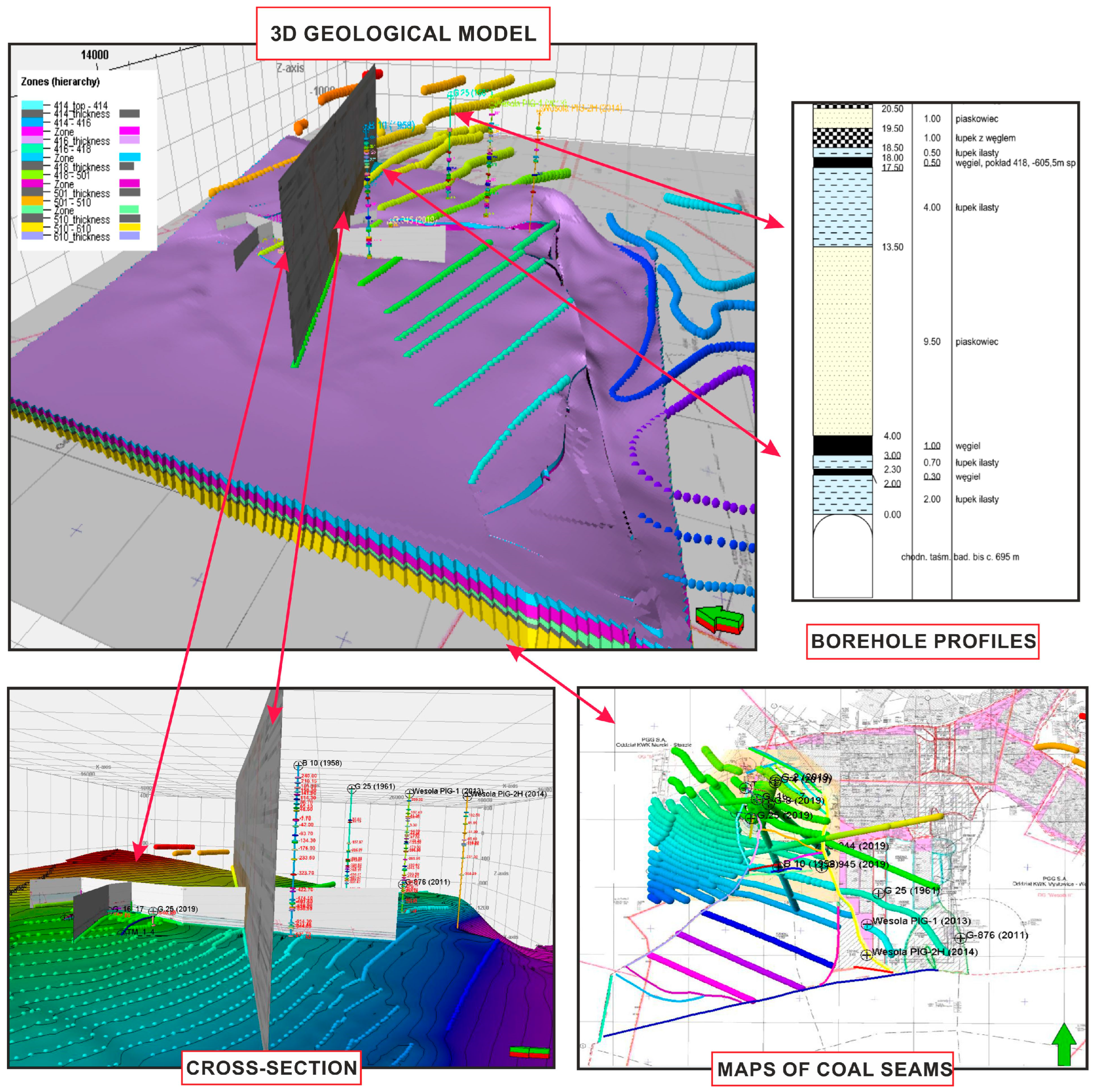
The data required for structural and parametric modelling were provided by the PGG Mining Group of the Department of Staszic-Wujek Coal Mine, as well as the PIG (Polish Geological Institute—NRI), as the owners of geological information from the W-1 borehole. The dataset consisted of results from laboratory measurements of various rock and fluid properties, well log data, borehole sedimentological profiles from 18 wells, and structural maps and cross-sections capturing the structural information of coal seams observed in the modelled mine. The wells included 3 deep surface research boreholes—B-10 (1958), W-1—PIG1 (2013), and W-PIG-2H (2014); 10 downholes—G-876 (2011), G-25 (1961), G-945 (2019), G-25 (2019), G-2 (2019), G-944 (2019), G-4 (2019), G-8 (2019), G-16 (2019), and G-17 (2019); and 5 LRDD draining boreholes drilled in 2019—TM-2, TM-3, TM-4, TM-5, TM-1/4, and TM-1A.
The maps included the geometry of the bottom and information regarding the thickness of the 510, 501, 418, 416, and 414 coal seams of interest. The use of general scale cross-sections aided the reproduction of the structure of more shallow-lying coal seams.
The well-log data from the W-1 borehole, approximately 1000 m long, was particularly important as the data set from this well contained a wide spectrum of geophysical profiling results to be used in a subsequent stage of petrophysical properties interpolation. The lithological profile in the area of interest, with well log data of the W-1 borehole used for interpretation, is shown in
Figure 1B. Despite this well not being located directly in the vicinity of the project’s area of interest, due to the drilled geological profile, set of measured logs, and laboratory data of the petrophysical parameters, it was found useful for drawing conclusions on a regional scale and extrapolating the results to the study area being modelled.
Two-scale geological modelling was implemented for the C sector in the Staszic-Wujek coal mine, using both a regional model and higher-resolution local models focused on drainage test areas. Both were able to capture the geometry of the 510, 501, 418, 416, and 414 coal seams and surrounding formations (
Figure 1C) as well as petrophysical/geomechanical properties from the overlying 610 coal seam to the surface.
The regional model incorporated all data, including data from the W-1 well, reducing structural uncertainty and enabling stress field determination affected by multi-seam mining activity. This model used a 25 × 25 m horizontal grid with vertical resolution varying from 10 through 20 m in overburden to approximately 5 m in drainage areas.
Local models used 1 × 1 m horizontal resolution with approximately 1 m vertical resolution in the 501 coal seam and surrounding strata to capture mine infrastructural details and wall face movement. These models incorporated all available structural and parametric data for subsequent coupled geomechanics and fluid flow numerical modelling.
The visualisation of data used for regional-scale geological model development with the well data location is shown in
Figure 2.
Development of 3D Parametric Models
The structural model presenting the geometry of the C sector of the Staszic-Wujek Coal mine was parametrised with petrophysical and geomechanical parameters, which is necessary in stress field calculations and the modelling of fluid flow in the area of methane drainage. The parametrisation was preceded by the modelling of lithotypes occurring in the area of interest.
The 3D lithotype model development was primarily motivated by the value of understanding the spatial distribution of lithotypes for geomechanical property modelling. The strong correlation between rock lithology and mechanical characteristics [
52] enabled more effective assignment of geomechanical parameters to specific lithotypes, which was particularly valuable given the limited geomechanical data available for the Staszic-Wujek coal mine area. The model of lithotypes’ distribution was constructed based on lithofacies profiles from 17 boreholes. In the borehole profiles (
Figure 1C), 7 main lithotypes were distinguished, further marked in the Figure with a specified color and numerical code as follows: 0—coal (gray), 1—coal shale (blue), 2—shale (purple), 3—sandy shale (beige), 4—sandstone (yellow), 5—conglomerate (orange), 6—sediments of Cenozoic age (green).
In the initial phase, digitised lithotype profiles from boreholes underwent upscaling based on lithotype representativeness in each interval. Geostatistical analysis using Petrel 2019 software determined lithotype proportions and variogram parameters defining spatial correlation in vertical and horizontal directions. The spatial distribution of lithofacies was estimated using sequential indicator simulation (SIS), with computations performed individually for each distinguished lithotype within the 3D model. The developed spatial facies distribution was then used to guide the modelling of both petrophysical and geomechanical properties in 3D space.
The models of density, porosity and permeability were constructed using data from two key sources: the profile of these petrophysical parameters from the W-1 borehole (derived from well-log interpretation) and laboratory measurements from 36 samples collected from the 501 coal seam near the drainage area [
53,
54]. Input data were averaged to match the vertical resolution of the 3D grid through an up-scaling procedure then subjected to statistical analysis performed individually for each lithotype.
Statistical analysis of the input data determined the parameters controlling modelled parameter interpolation within the 3D structural model space. A stochastic algorithm—Gaussian random function simulation—was employed to model the spatial distribution of density, porosity, and permeability. The modelling process was executed 25 times, generating equally probable 3D porosity distributions. These distributions were then averaged to create the final 3D models of density, porosity and permeability.
4. Geomechanical Model
The models of stress and strain fields were developed based on the static parametric models of petrophysical and mechanical properties of lithotypes occurring in the Staszic-Wujek coal mine. The parametric models presenting the spatial distribution of geomechanical properties were developed based on well log data recorded in the W-1 reference borehole, as well as laboratory measurements of rock samples collected from the drainage zone.
The 1D models of elastic properties (including Young’s modulus and Poisson’s ratio) and strength properties (such as unconfined compressive strength (UCS) and tensile strength (T)) were developed using well log data from the W-1 borehole. For the estimation of dynamic elastic properties, we used compressional wave velocity (
), shear wave velocity (
), and rock density (ρ), utilising the following Formulas (1) and (2) [
55]:
where
stands for the dynamic Poisson’s ratio,
denotes the dynamic Young’s modulus,
and
are the compressional shear wave velocities, respectively, and ρ is the rock density.
To determine static equivalents of elastic and strength properties for particular lithotypes occurring in the W-1 borehole profile, we used empirical models reported in the literature that describe the relationship between dynamic and static elastic properties for specific lithotypes [
56,
57,
58].
In
Figure 3, track 3 displays the developed static geomechanical properties alongside lithological interpretation (track 1) and input data (track 2) including compressional wave velocity (
), shear wave velocity (
), rock density (ρ), and gamma ray (GR).
Each of the three distinguished lithotypes was assigned an appropriate model [
56,
57,
58] to calculate static equivalents of elastic properties (track 3 in
Figure 3). For UCS estimation, relationships between this parameter and Young’s modulus were used for both sandstones and sandy shales [
58], while a relationship between UCS and porosity was utilised for shales [
56]. Tensile strength was determined using the formula proposed by Hoek [
59] that describes the relationship between tensile strength and unconfined compressive strength.
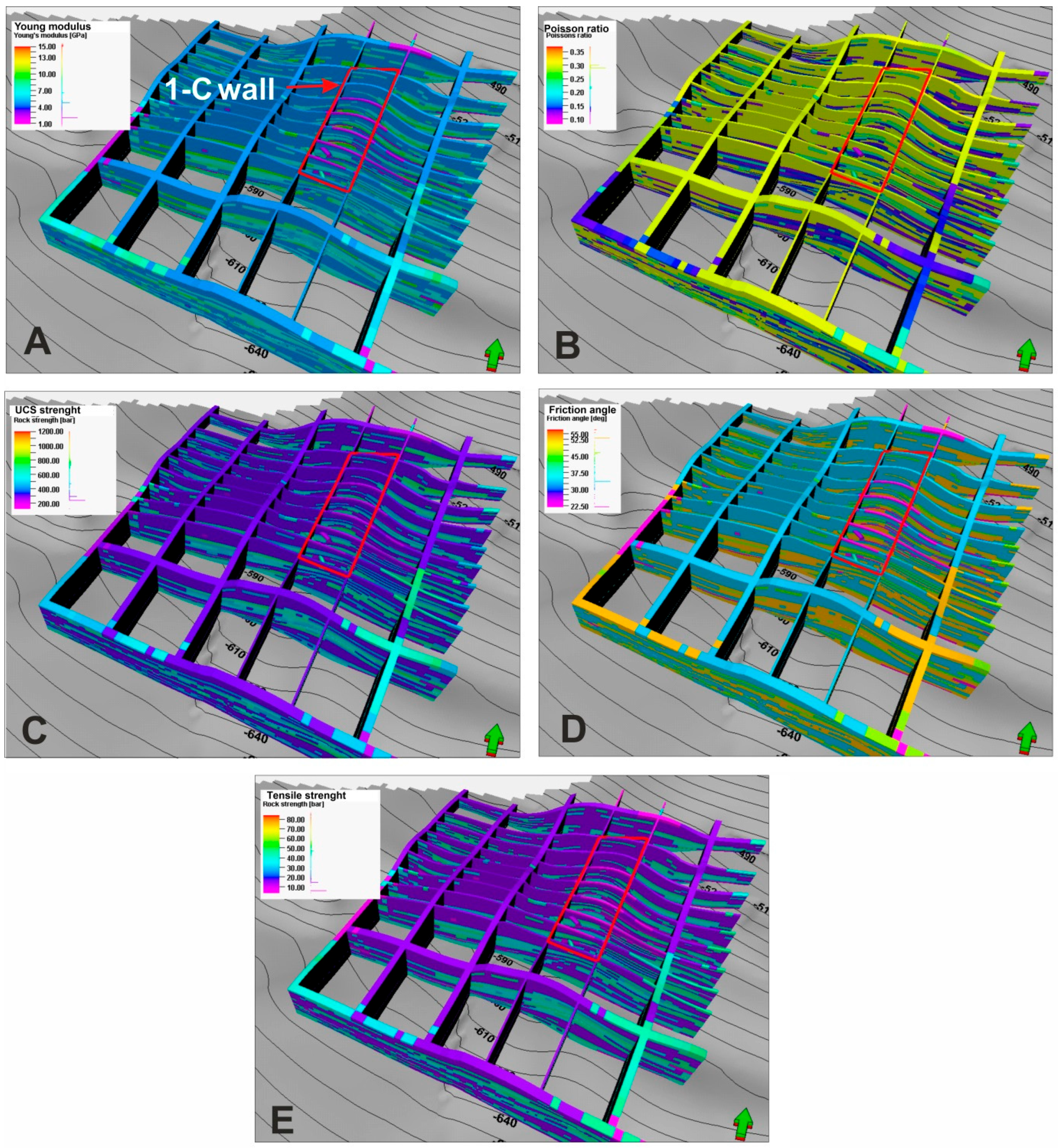
Three-dimensional models of geomechanical parameters were developed using the estimated static geomechanical properties (Young’s modulus, Poisson’s ratio, and UCS) from the W-1 borehole profile. During modelling of geomechanical properties near the drainage area, results from geomechanical measurements of samples collected in the drainage area, archival laboratory measurements shared by the mine operator, and data from the literature for other strata were incorporated. The value ranges for specific parameters and their source references are provided in
Table 1 [
60,
61,
62,
63,
64,
65].
Before data analysis, the input data were averaged to the vertical scale of the 3D model. During the geostatistical analysis, variogram parameters were defined, and spatial relationships between input data were determined for calculating the distribution of geomechanical parameters in 3D space. This procedure was performed individually for each lithotype.
The modelling of geomechanical properties utilised the Gaussian random function simulation algorithm, calculating 25 equally probable realisations, which were then averaged to create the final 3D distribution of mechanical properties (
Figure 4). The developed models of geomechanical properties, similar to the petrophysical 3D models, took into account the effects of the mining works carried out so far, manifesting in local changes in the properties of the rock material in the mining zone.
Models were developed on a regional scale to capture the entire scope of data and local scale models of higher resolution in the area of the IC-panel in the zone of drainage.
The models constructed on a local scale, visualised in
Figure 4, were further used as an input for modelling of fluid flows as well as geomechanical simulations to calculate the changes in stress and strain field with the progression of the mining works. The stress and strain field were calculated using the finite element geomechanical simulator Visage (Schlumberger). The initial effective stress conditions within a reservoir and its overlying rock formations are described using the following Formula (3) applicable to isotropic rocks [
66,
67].
where
is the minimum horizontal stress, ν is the Poisson’s ratio,
is the vertical stress, α is the Biot’s constant,
is the pore pressure, and
is the tectonic pressure.
To reproduce changes in stress and strain fields resulting from mining activity, specifically the IC-panel initialisation and its longwall movement, initial pore pressure distribution and boundary conditions were determined.
A pore pressure model was developed to calculate effective stresses using Terzaghi’s principal Formula (4) [
68]:
where
stands for the effective stress,
is the total stress, and
is the pore pressure.
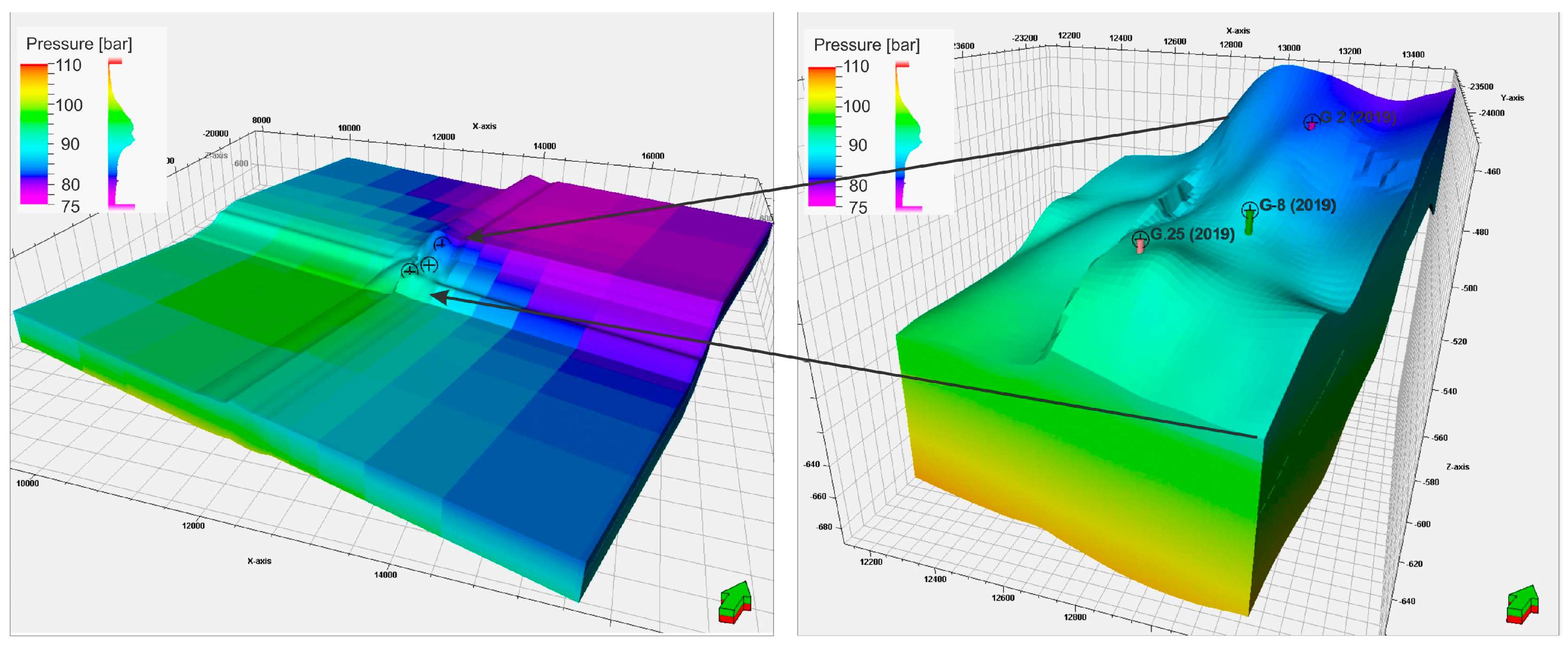
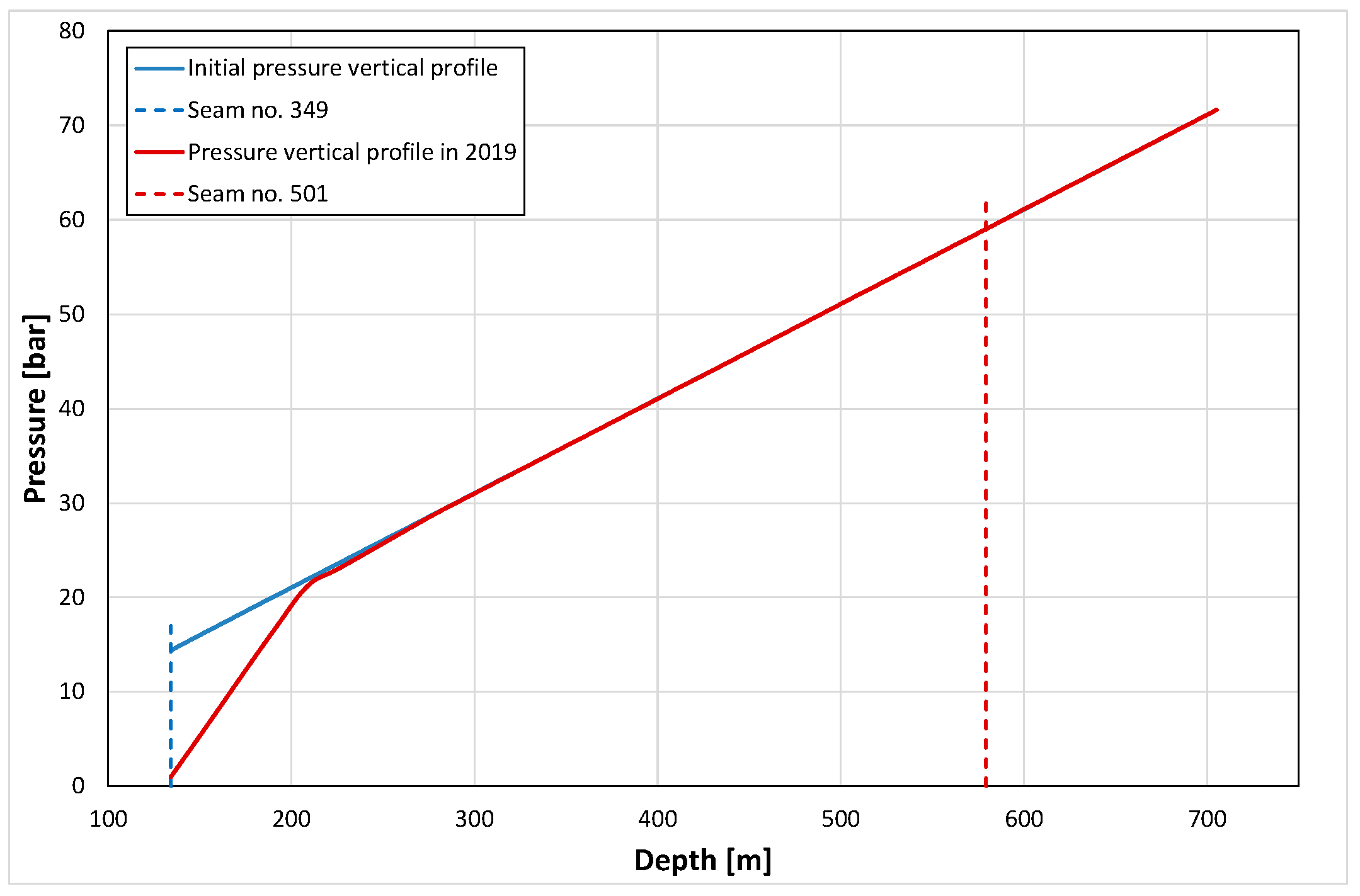
The distribution of the initial pore pressure in the Staszic-Wujek coal mine was determined based on the work by Różkowski et al. [
69]. In their research, due to the different content of solids dissolved in the underground waters within the USCB, the authors distinguished five 200 m thick zones in the profile (
Table 2). This solid content, causing an increase in water mineralisation with depth and corresponding rise in the hydrostatic pressure gradient, was used to determine the pore pressure gradients in these zones and, consequently, the 3D distribution of pore pressure (
) in the research area.
The hydrostatic pressure at the level of the 501 coal seam in the vicinity of the IC panel was determined to be 94 bars (at true vertical subsea depth of −585.5 m). The visualisation of the calculated 3D distribution of pore pressure in the study area is presented in
Figure 5. The estimated pore pressure was then used in the geomechanical simulations to obtain the initial stress field.
Geomechanical Boundary Conditions
To determine the initial stress conditions, we applied the load of the overlying rocks and tectonic stresses as boundary conditions. Based on the interpretation of borehole wall images available in the W-1 borehole capturing the drilling-induced damage observed in the wellbore wall, such as breakouts and drilling-induced fractures (DIFs), the direction of present maximum horizontal stress
σH was determined [
70]. The azimuth of the DIFs was between 90 and 110° (ESE). These directions are consistent with the findings of Dubiński et al. [
71], who stated that the maximum horizontal stress azimuth in the close vicinity of the study area is 99° (ESE).
The gradient of the minimum horizontal stress
was determined to be approx. 0.1707 bar/m based on mini-frac tests in the nearest available borehole location [
72]. The stress regime in the study area was assumed to be normal faulting according to the studies carried out in the area of interest [
71,
73]. The anisotropy between principal horizontal stresses
/
was also determined to be 1.25, based on the findings from the literature using the reference borehole [
72]. The initial stress conditions in the Staszic-Wujek coal mine are listed in
Table 3.
During geomechanical simulations coupled with dynamic reservoir fluid flow modelling, pressure changes induced by the advancing longwall front led to the redistribution of stress and strain fields. This, in turn, caused both elastic and plastic deformations. When the evolving stresses exceeded the critical strength of the rock mass (as listed in
Table 1), failure occurred according to the Mohr–Coulomb criterion used in simulations, ultimately affecting the transport properties of the reservoir, as discussed below.
5. Dynamic Model
Based on the geological and geomechanical characterisations employed to generate the corresponding geological and geomechanical models, dynamic models of the selected IC panel of the 501 coal seam and its surroundings were constructed. A standard double-component system was assumed in coal seams of the analysed structure; this comprised cleats containing free fluids (gas and water) and described by multiphase viscous flow and matrices containing adsorbed gas and described by the diffusion type of gas transport. The other regions of the model (clastic rocks) assumed conventional single-porosity systems.
To complete the dynamic model construction, additional components of the models were determined as follows:
- (a)
Thermodynamic model of the reservoir gas:
the thermodynamic properties of the reservoir gas were determined by the Peng–Robinson equation of state (gas formation volume factor) and by the Lorentz–Bray–Clark correlation (gas viscosity) from gas composition, which are presented in
Table 4.
- (b)
Capillary pressure:
the dependence of capillary pressure upon water saturation was implemented from the provided measurements—the capillary pressure determined the distribution of pressure and water/gas saturations for initial hydrostatically balanced conditions.
- (c)
Relative permeabilities of reservoir fluids:
due to the lack of proper measurements, relative permeability curves (krg/w vs. Sg/w) were assumed to be of conventional types, i.e., linear for the naturally fractured coal and power-like for the porous clastic rocks.
- (d)
Adsorption/desorption isotherm of methane:
the Langmuir adsorption/desorption isotherm was determined as an average dependence from the provided measurement data described by the Formula (5):
where
is the concentration of the adsorbed methane as a function of pressure,
, parametrized by asymptotic concentration
= 11.25 Sm
3 of gas/m
3 of coal and characteristic pressure
= 7.3 b,
The above Langmuir isotherm was obtained as an average of 23 measurements on samples obtained from different depths. They covered the pressure range of 0–18 bar.
- (e)
Trajectories of drainage boreholes;
trajectories and completions of both conventional and directional methane drainage boreholes were implemented from the geological model of the structure and other technical parameters provided by the Murcki-Staszic mine operator, Jastrzębska Spółka Węglowa, Jastrzębie-Zdrój, Poland.
- (f)
Schedule of gate-road making:
a detailed schedule of the gate-road excavation around the IC panel of the 501 coal seam was implemented into the dynamic simulation model to estimate the road’s influence upon the pressure and reservoir fluid distributions and to obtain the state of the analysed panel before the mining longwall activities.
Initial Conditions
Based on the information concerning the state of the structure elements surrounding the analysed coal seam, the dynamic model was applied to simulate their impact upon the IC panel of the seam. In particular, two factors were analysed in detail, as described below.
The results of the simulations proved the negligible influence of the 349 coal seam upon the 501 coal seam.
- 2.
Gate-roads:
The constructed simulation model of the structure was used to determine the influence of the gate-roads around the IC panel on pressure distribution and desorbed methane content in the analysed coal seam and its surroundings. It was assumed that the gate-roads were excavated gradually according to the provided schedule and ventilated proportionally to the length of the completed roads.
In both the static (geological and geomechanical) and dynamic modelling described above, the effects of temperature variations were neglected due to the following reasons:
- (a)
The depth variations of the models and, consequently, the initial temperature variations were small;
- (b)
Dynamic temperature variations during the IC panel excavation were also negligible due to the very small gas (injected air) heat capacity compared to the heat capacity of the rocks.
6. Effective Coupling of Geomechanical and Fluid Flow Simulations
To study geomechanical effects, numerical modelling of fluid flow coupled with a geomechanical analysis of the medium [
74,
75,
76,
77] was applied. This coupling was achieved by partially coupled numerical simulations based on an external coupling between separate numerical simulations [
74,
76,
78,
79,
80].
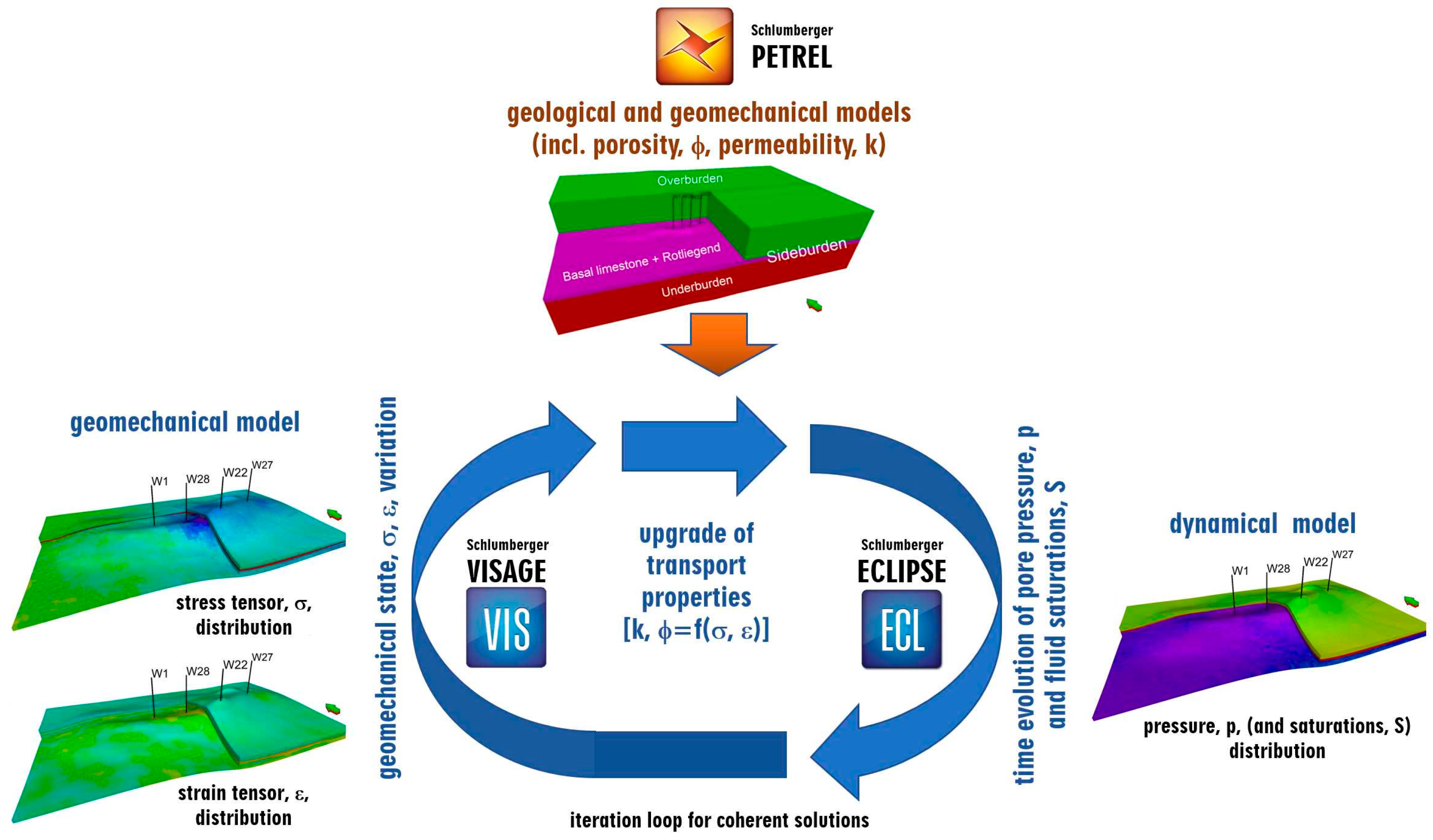
The fluid flow simulations resulted in variations in the pressure and fluid saturation distributions that, together with general rock and fluid characteristics, determined the geomechanical properties of the system. Based on those results and properties, the geomechanical simulations resulted in variations in the geomechanical state (stress and strain), thus affecting the transport properties of the system to be used in the flow simulations [
75,
81,
82]. The two simulations were iteratively coupled at each time step. The schematic of this approach is shown in
Figure 7.
A detailed description of the simulation coupling method used in this study was given in an earlier paper [
83].
7. Geomechanical Effects
Three types of rock deformations were recognised: elastic, plastic, and failure. The elastic ones are strictly dependent on pressure variations and are different for each type of rock. Their range is not limited; however, their amplitude is relatively small. Although precisely included in the general procedure, it will not be discussed in detail here. Instead, plastic and failure-type rock deformations are presented thoroughly below. Based on the analysed results of geomechanical simulations, significant changes were observed in the diagonal components of stress and strain tensors to occur within the limited-range vicinity of the coal workings in all directions, confirming the plastic and failure type of the deformations within those regions.
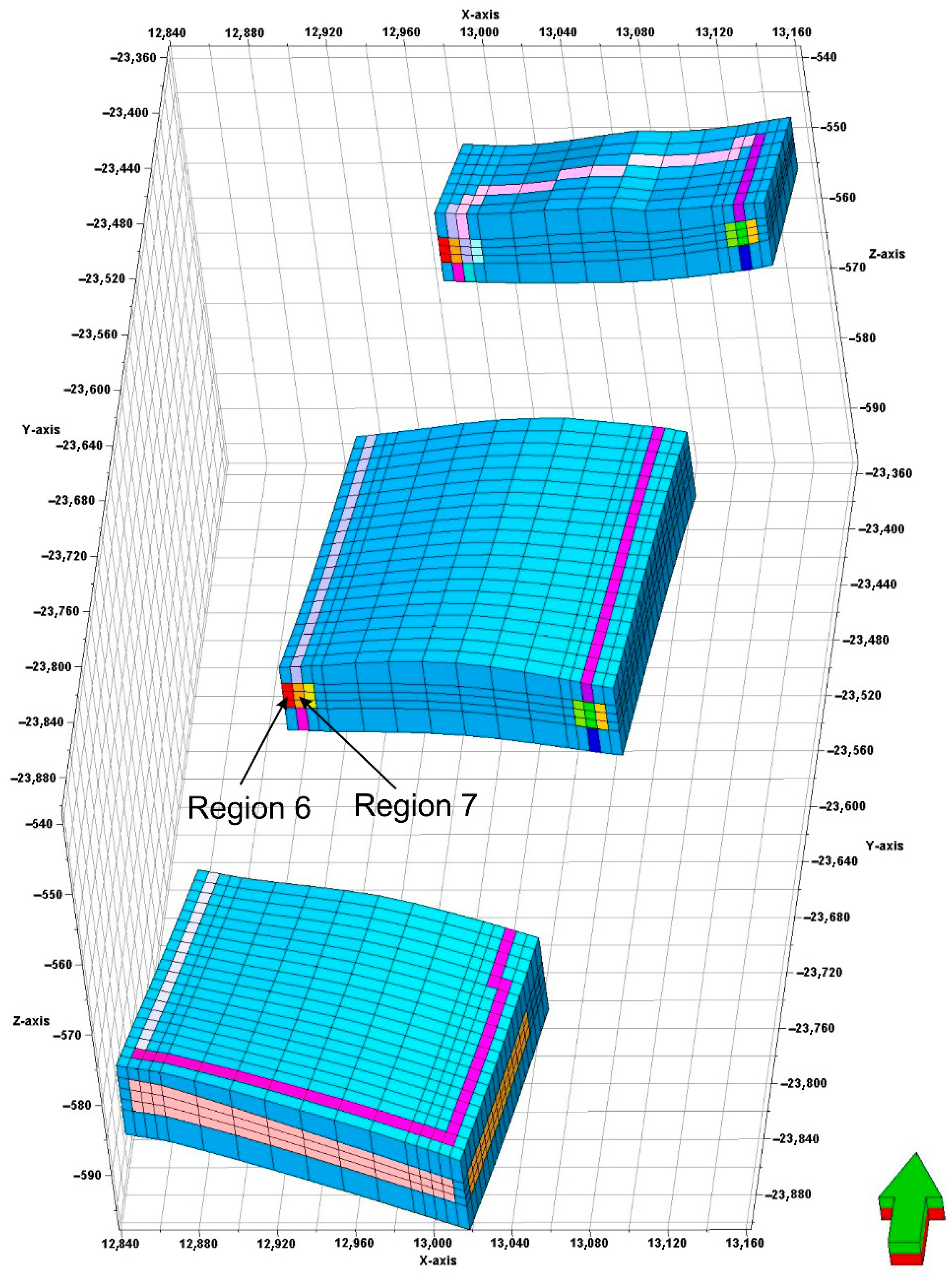
The blocks around the gate-roads were grouped into several regions according to the major spatial directions following the route of the gate-roads around the analysed panel. Exemplary Regions no. 6 and no. 7 are shown in
Figure 8.
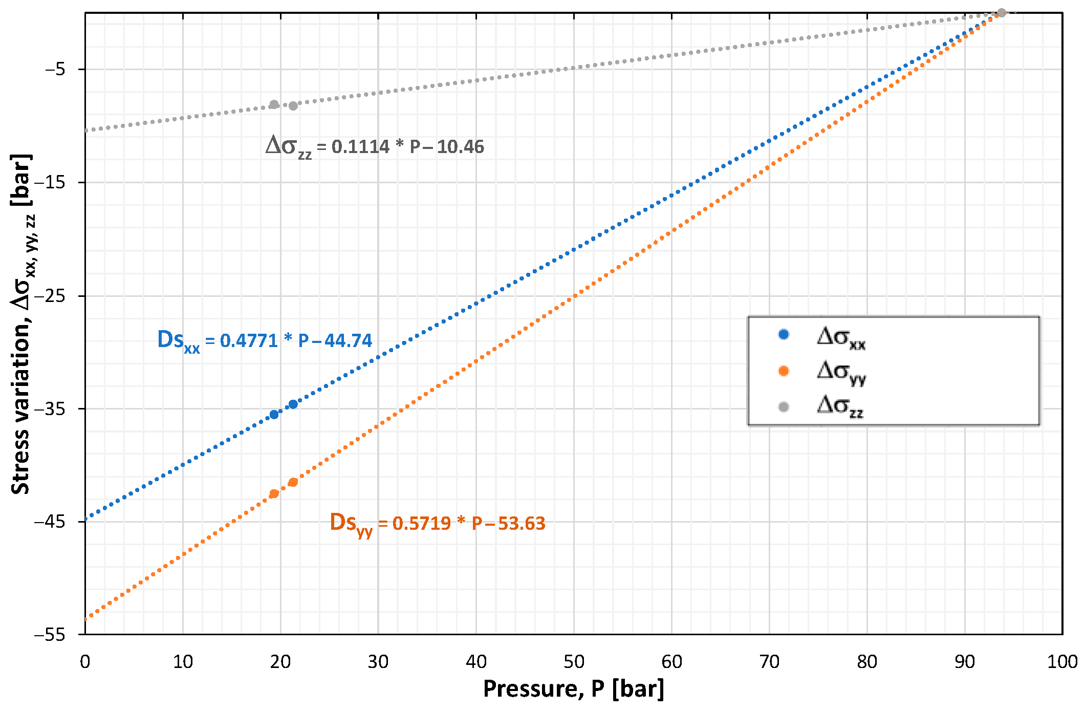
Changes in the stress tensor components were correlated with the changes in pressures in individual regions (
Figure 9).
Next, transport properties in terms of inter-block transmissibilities were analysed for successive time steps. To relate changes in the components of the stress tensor with the changes in the transmissibilities, the relationship (6) proposed by J.Q. Shi and S. Durucan [
84] was employed:
where
—stands for the modified/original i-th component of the transmissibility,
—stands for pore compressibility,
—stands for the change in the diagonal stress component, ,
—stands for Kroncker’s delta function.
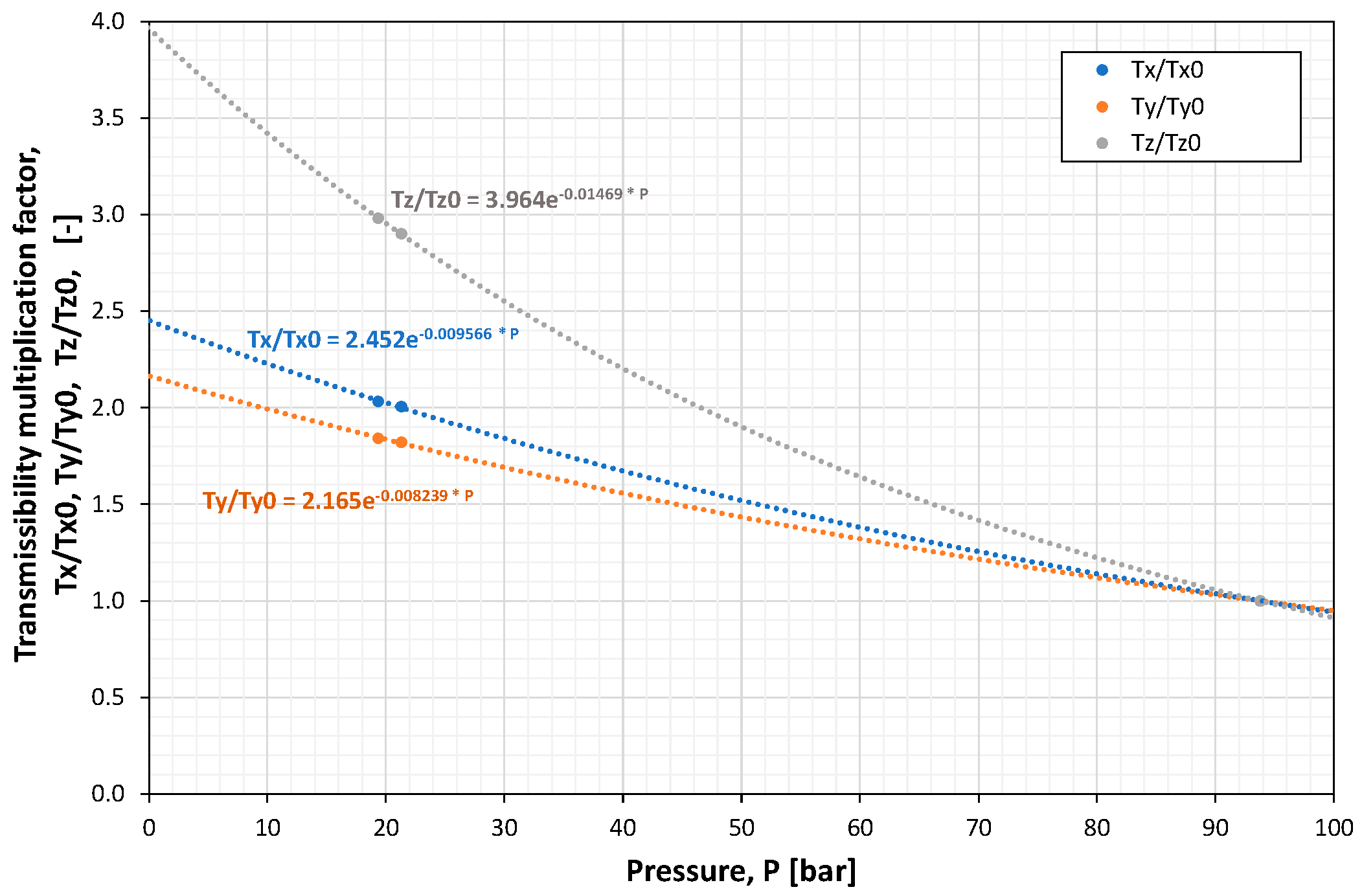
Effective dependence of transmissibilities (transmissibility multiplication factors) on pressure was found as presented in
Figure 10 for the example of Region no. 6. During the flow simulations, the effective changes of the inter-block transmissibilities, resulting from the pressure changes, were implicitly performed, taking into account appropriate simulator functions for the multiplicative transmissibility coefficients.
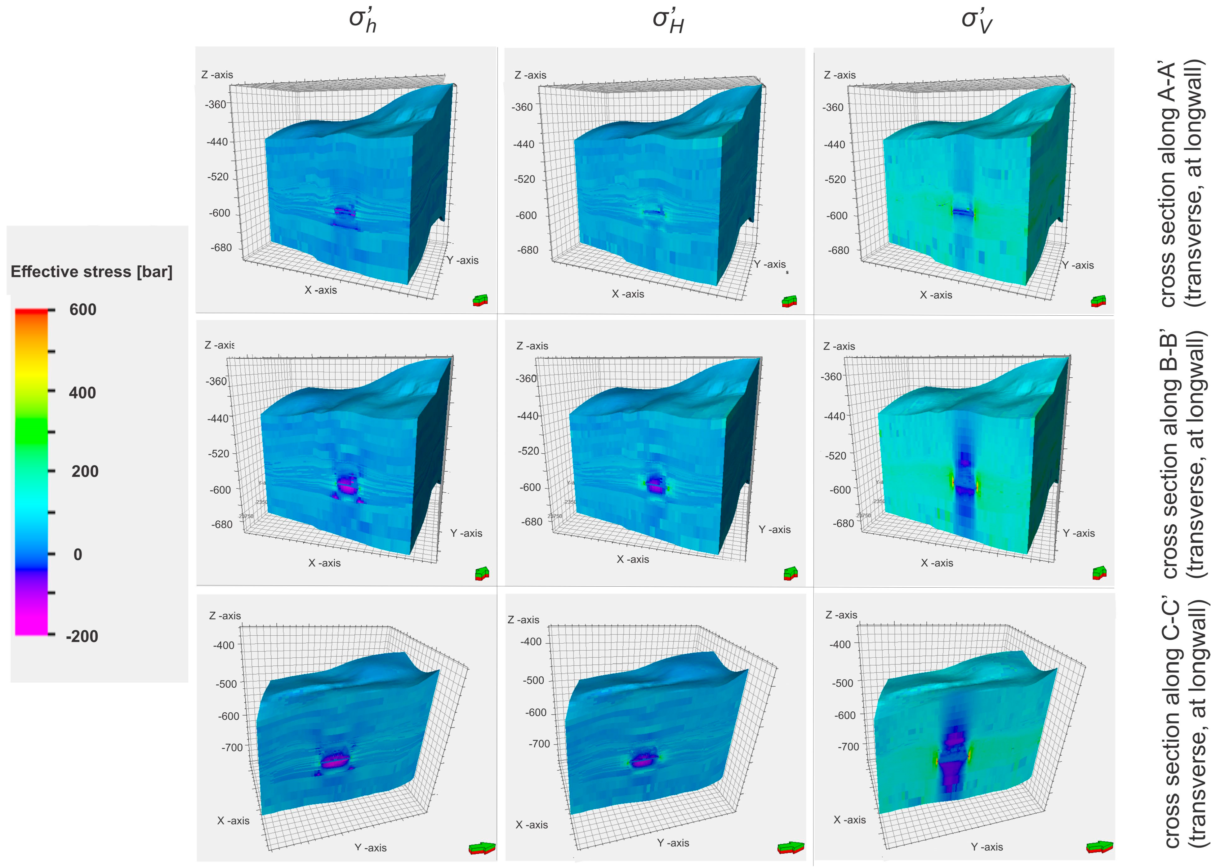
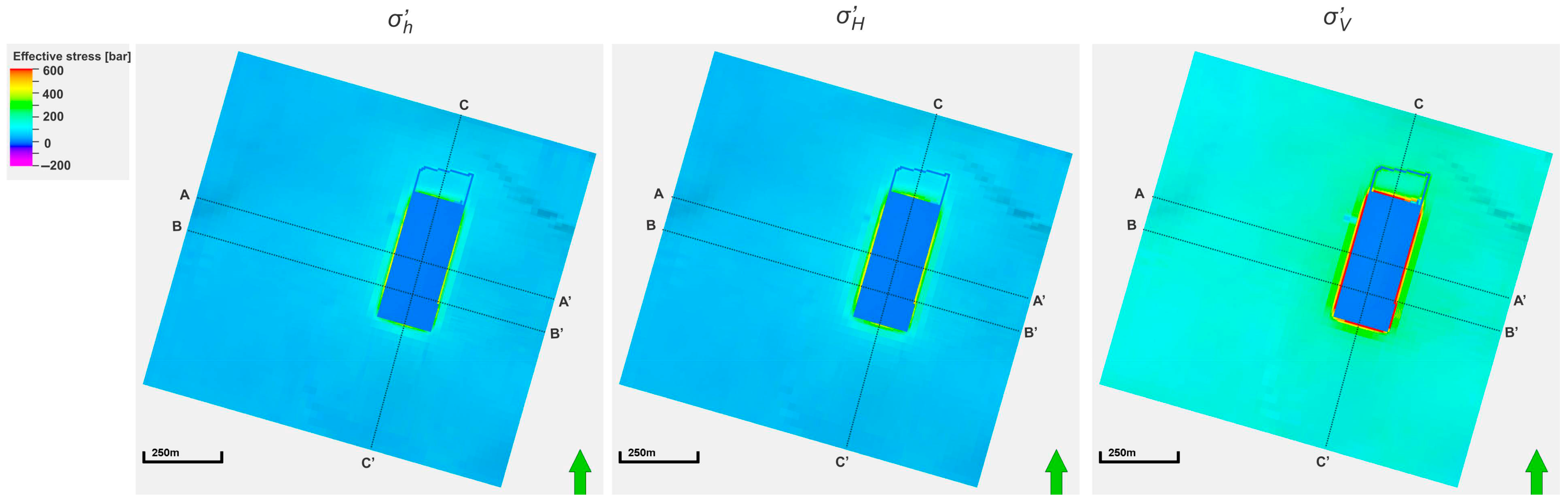
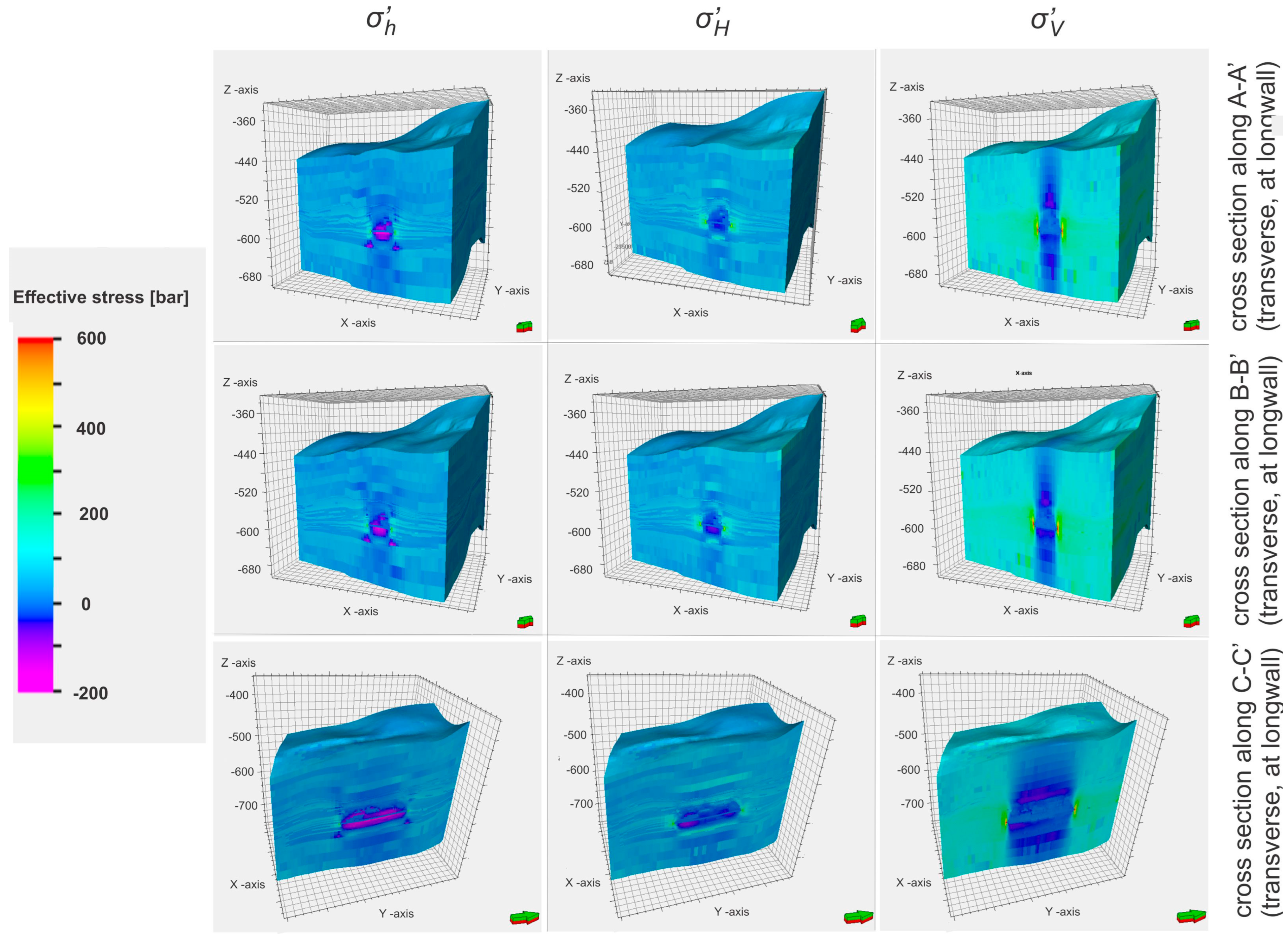
Excavation of the analysed coal seam caused further significant modifications of the geomechanical state of the unmined coal seam and rocks surrounding the excavated part of the seam. Consequently, the modifications affected the transport properties of those rocks. Examples of the distributions of the geomechanical state variations are shown in
Figure 11,
Figure 12,
Figure 13 and
Figure 14 for two selected excavation advancements:
Figure 11 and
Figure 12 for partial (50%) excavation progress and
Figure 13 and
Figure 14 for the complete excavation of the analysed panel of the 501 coal seam. Those distributions included three principle components of the effective stress tensor (σ’
h, σ’
H, σ’
v) within the mid-depth surface of the 501 coal seam (
Figure 11 and
Figure 13) and 3D views (
Figure 12 and
Figure 14) of those distributions on the side walls of the model with front walls along the cross-section lines A-A’, B-B’, and C-C’ defined in
Figure 11.
An analysis establishing relations between pressure distribution, geomechanical states (stress tensor), and transport properties was made to apply the effective method of coupled geomechanical and flow simulations. Stress tensor variations resulted in changes in rock transport properties (transmissibilities) according to the Formula (6) by J.Q. Shi and S. Durucan given above.
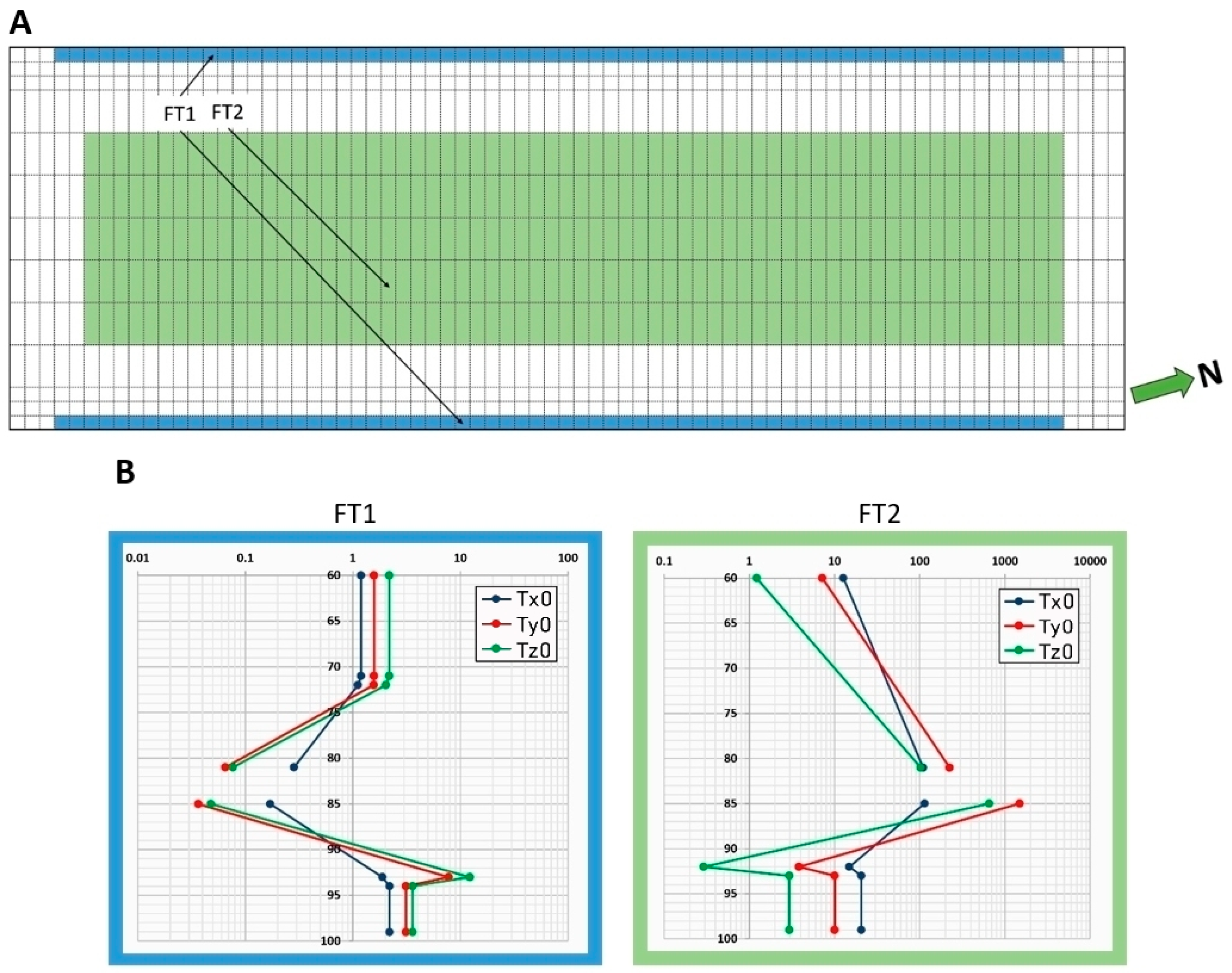
To draw conclusions concerning the geomechanical effects of the unmined coal seam and rocks surrounding the excavated part of the IC panel upon transport properties (transmissibilities), common trends of the transmissibility multiplication factors were identified and found to depend on the distance from excavated regions of the IC panel. Detailed distributions of the transmissibility multiplication factors are shown for various regions in
Figure 15 upon partial (50%) excavation and in
Figure 16 upon complete excavation as a function of depth expressed by the model layer numbers.
The above results of the analysis concerning the influence of geomechanical states upon the transport properties of unmined parts of the 501 coal seam and rocks surrounding the seam were applied to the calibration procedure of the analysed simulation model described below.
8. Model Calibration
The calibration procedure of the model was based on the following list of historical data related to the coal production from the IC panel of the seam.
Schedule and measurement data from the gate-road excavation and ventilation before the coal excavation from the panel, including air injection, total gas (combined air and methane) production, and methane production of the ventilation system vs. time (from 29 January 2018 to 31 August 2019),
Schedule and measurement data from the panel coal production, including air injection to the ventilation system and total gas and methane production by three elements of the methane drainage system: the ventilation system, the standard methane drainage boreholes, and the directional methane drainage boreholes vs. time (from 1 September 2019 to 28 February 2020).
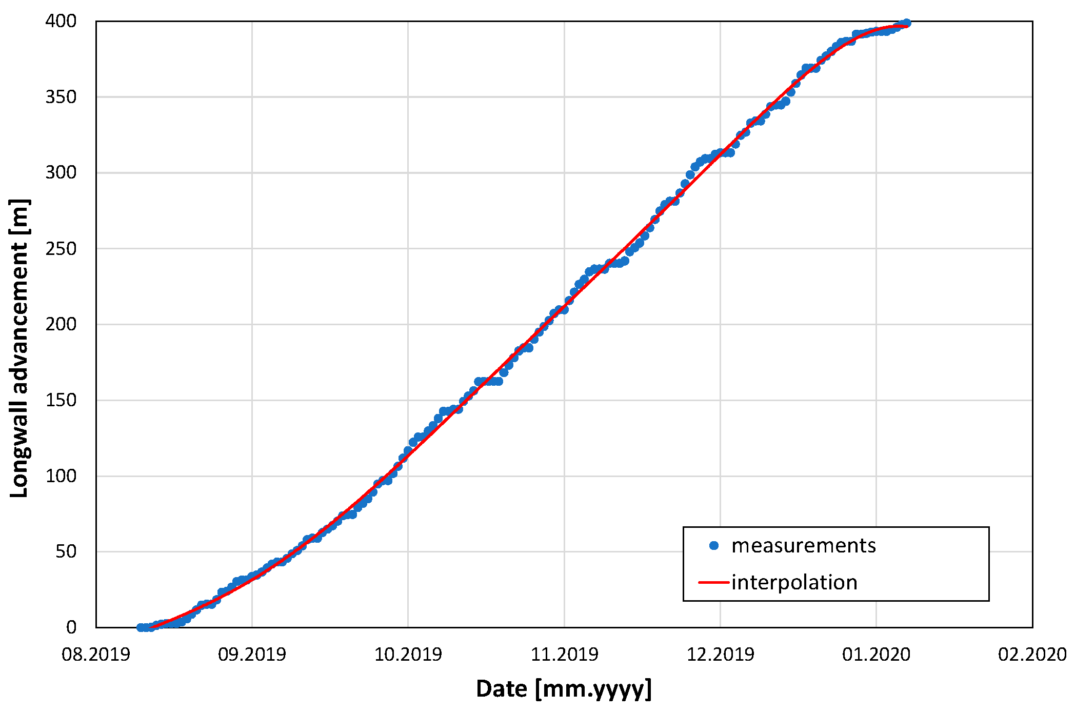
In addition, the historical data included the pressure conditions of the ventilation system and the methane drainage boreholes. The schedule of the IC panel coal production is presented in
Figure 17 as the longwall advancement.
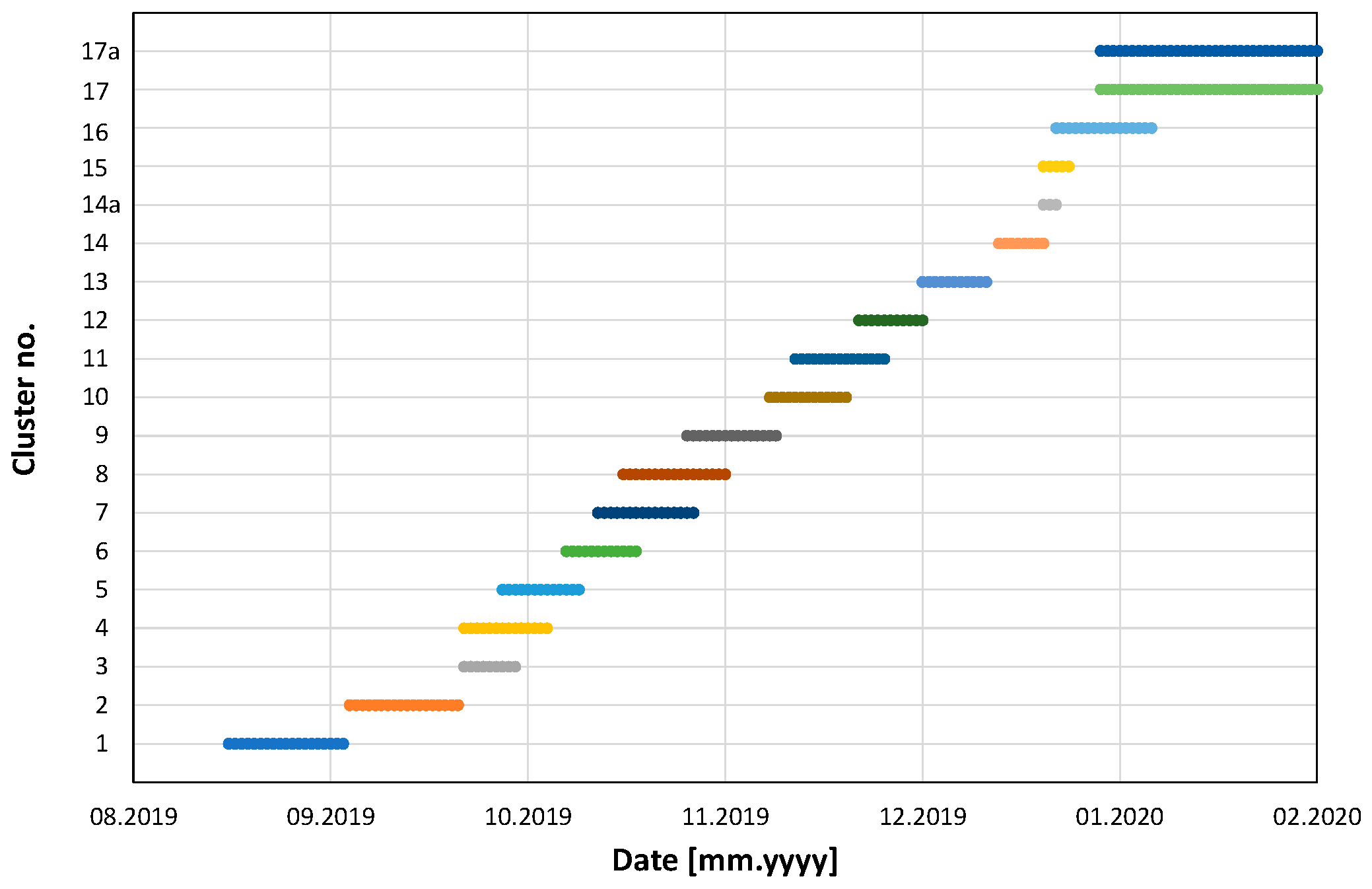
Similarly, the schedule of the standard clusters of drainage borehole activities (the cluster production intervals) is shown in
Figure 18 for the boreholes grouped into 19 clusters.
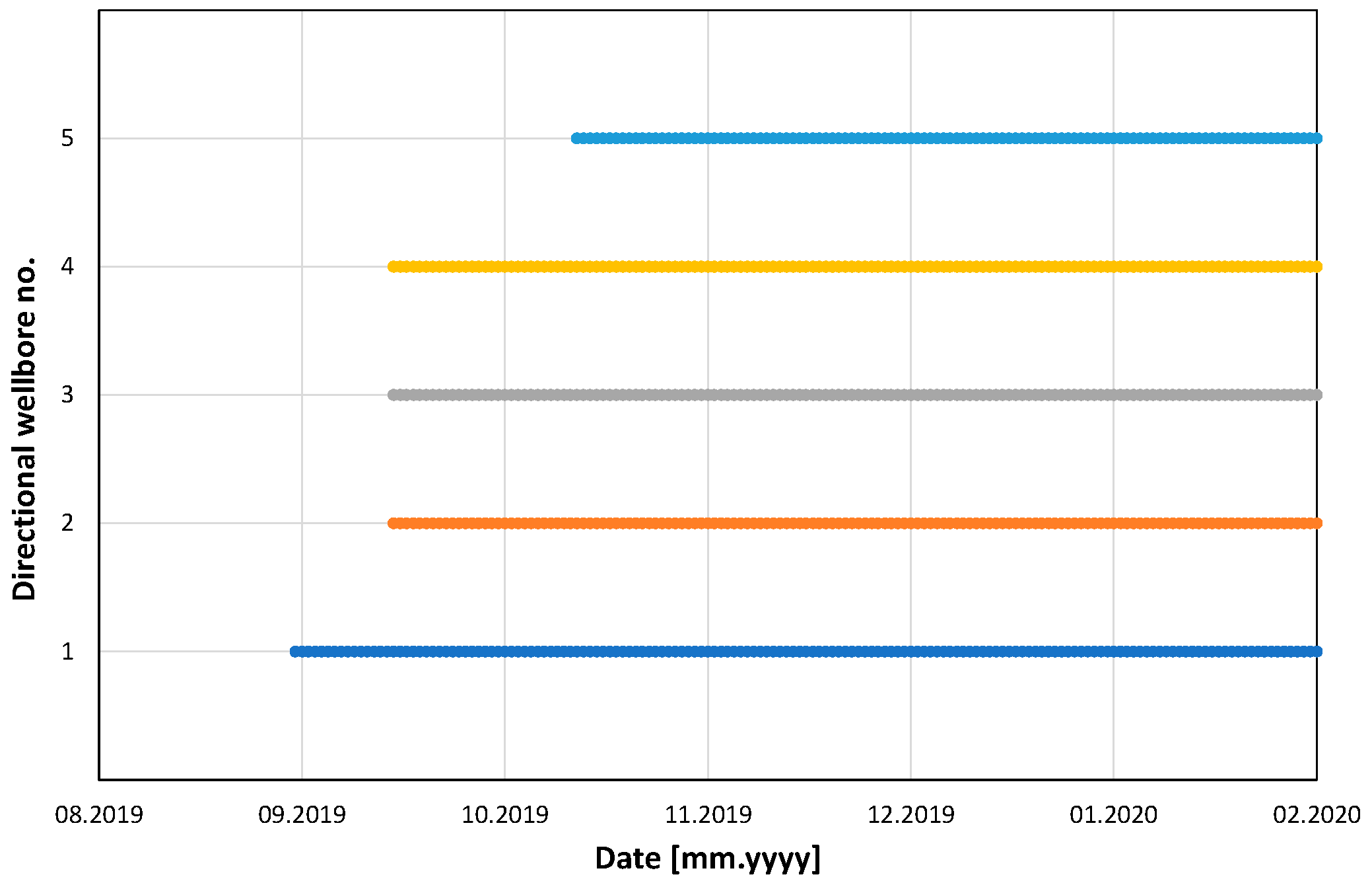
Furthermore, the schedule of the directional borehole activities (the borehole production intervals) is shown in
Figure 19.
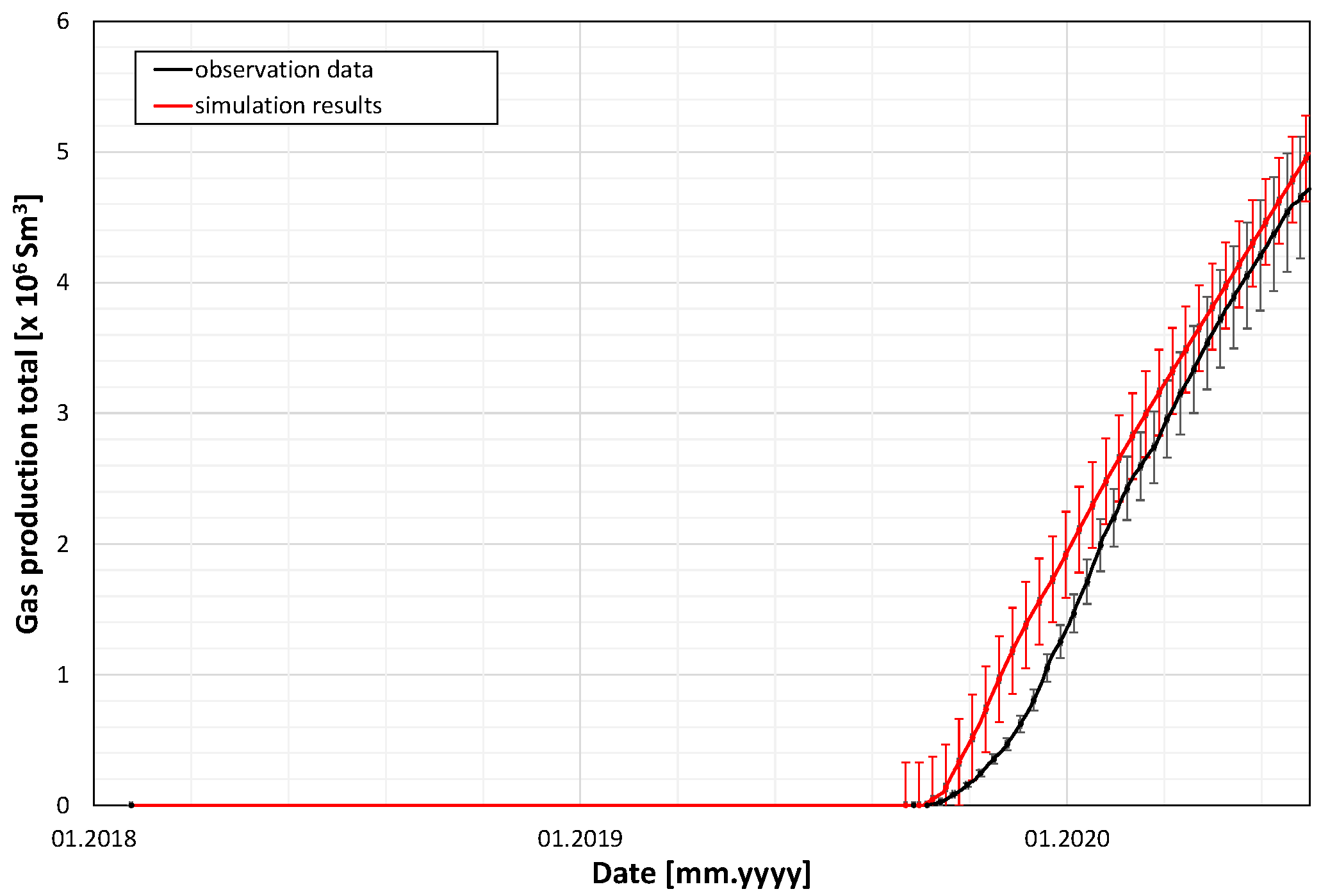
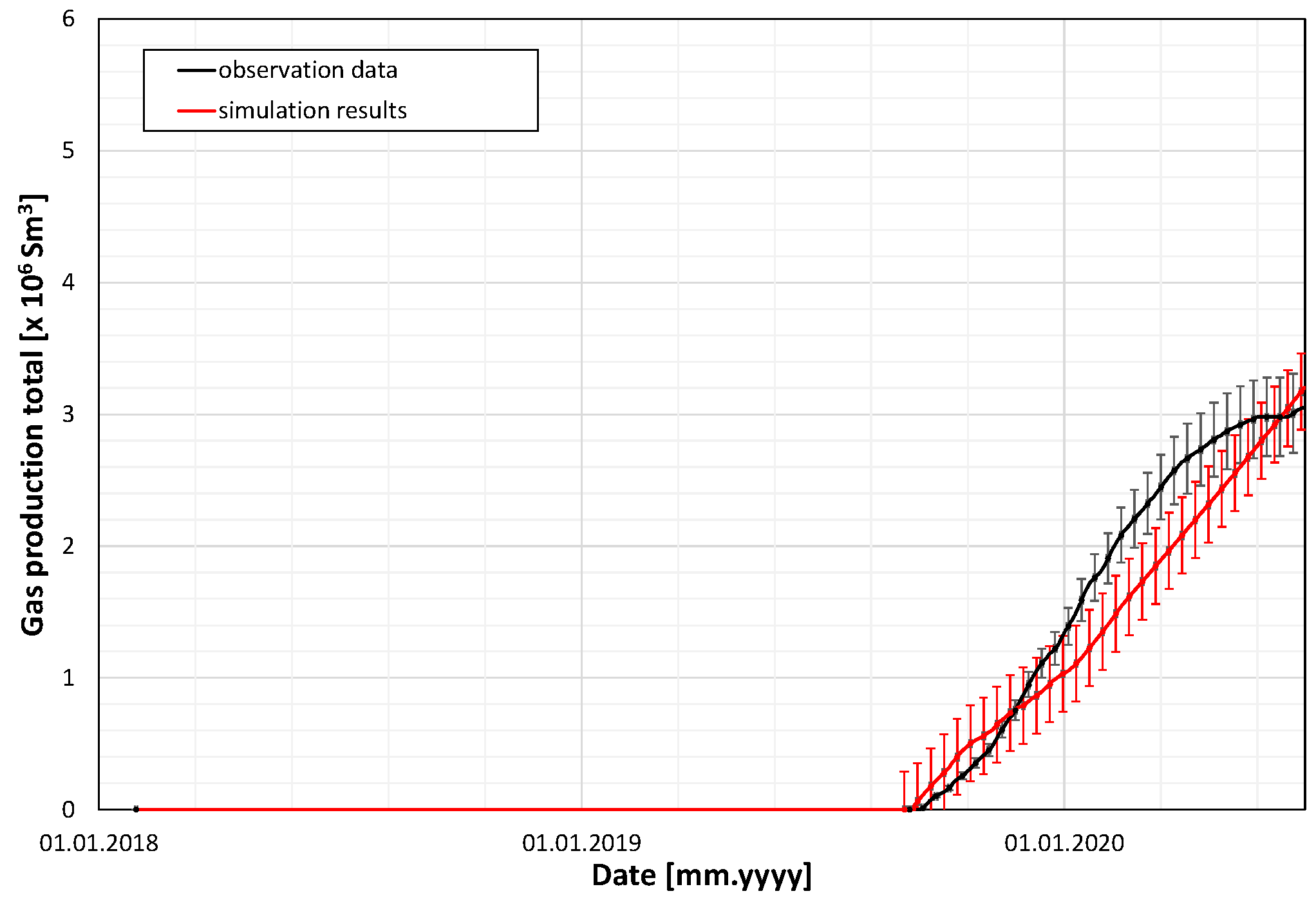
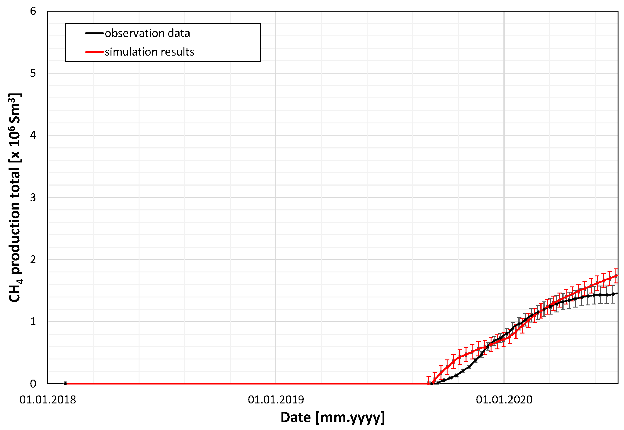
The basic measured data of the methane ventilation and drainage processes during the coal production from the IC panel included the following:
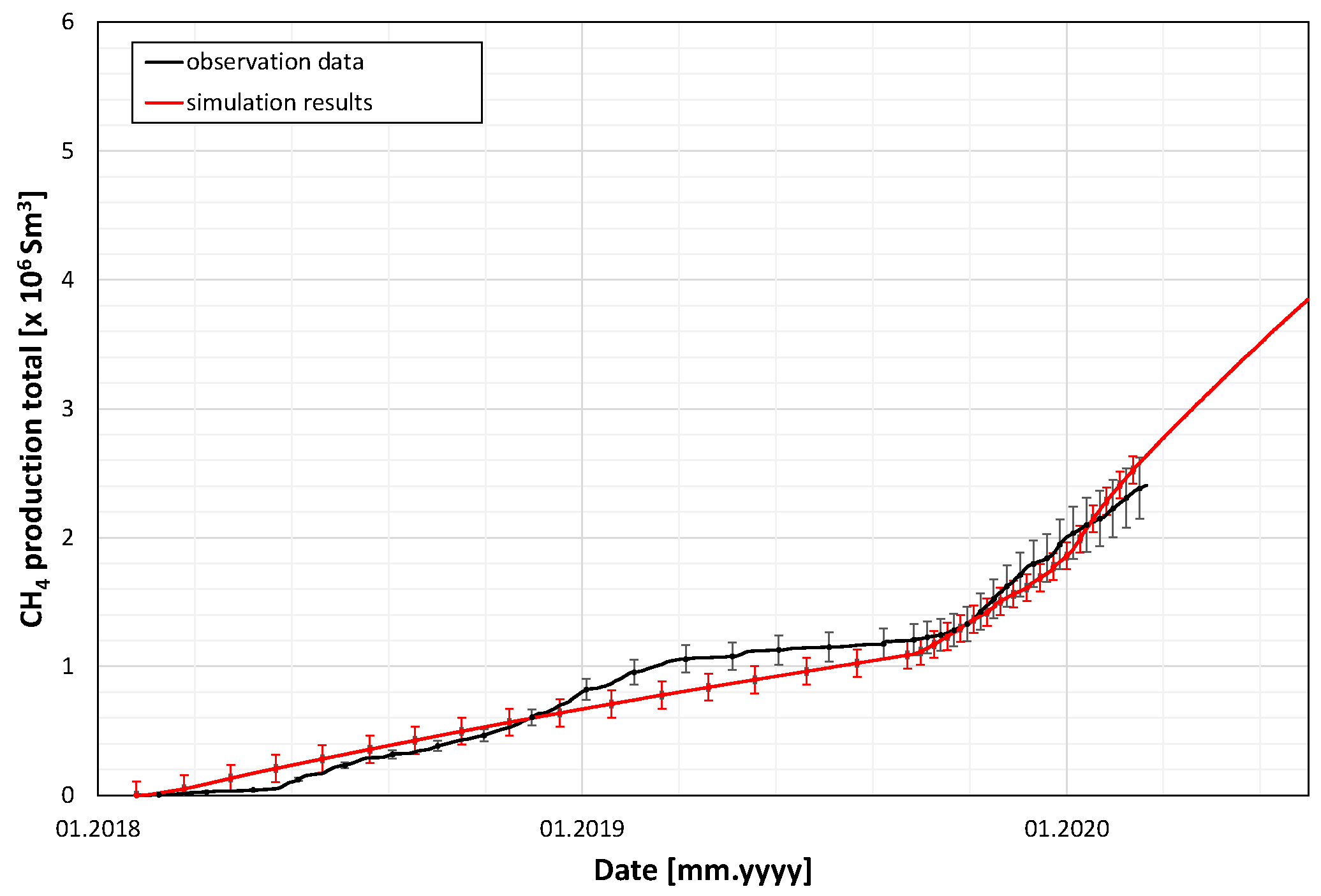
Among the above seven items, the first was treated as a control variable, and the other six were history-matched to calibrate the model through multiple simulation runs.
The main data series in these Figures are supplemented with error bars attached to both measurement data and simulation results. The former indicates typical errors of measurements (with a relative error of 10%), and the latter corresponds to estimated mean absolute deviations (MADs) as measures of goodness of fit for the above six items. The precise values of MAD, defined as
are included in
Table 5 together with average measurement error (AME) and their ratio (MAD/AME). In the above formulas, the following symbols are used:
—total number of data points,
—simulation result, ,…, ,
—measurement data, ,…, .
The above results of the goodness of fit show a satisfactory agreement between the measurement data and the simulation results, confirming good reliability of the model to correctly describe the methane drainage taking place during the coal production from the IC panel of the 501 coal seam.
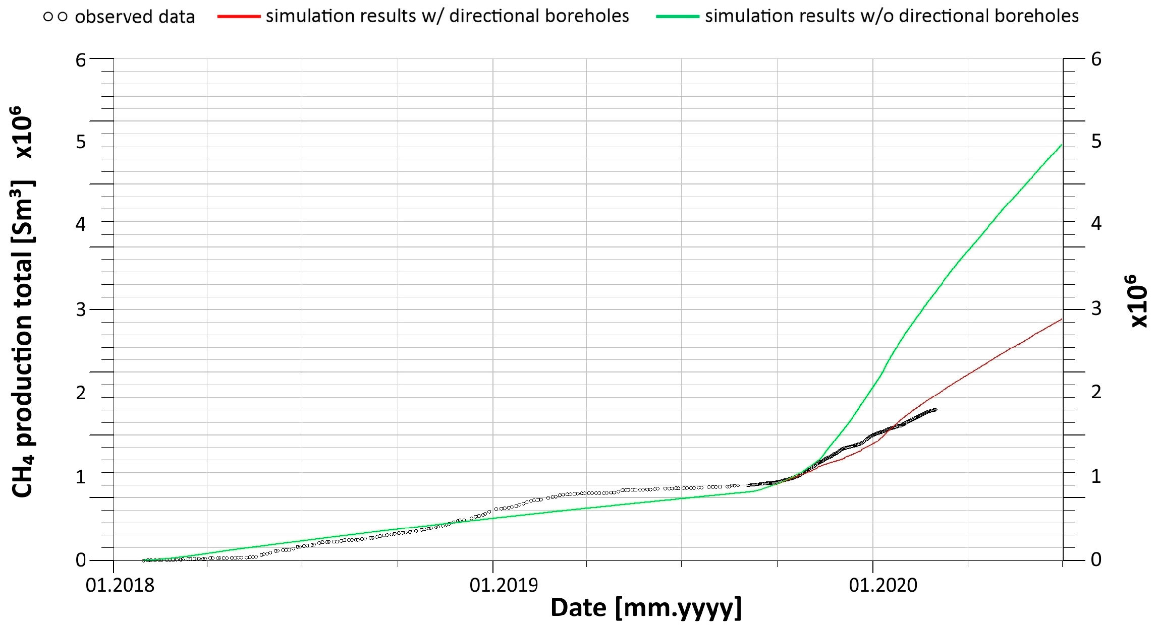
9. Effectiveness of Methane Drainage by the Directional Boreholes
The calibrated model of the 501 coal seam and its surroundings, as described above, was used to simulate a hypothetical scenario that did not use directional boreholes for methane drainage. The fundamental results of that simulation in terms of total methane production by the ventilation system, with analogous results for the scenario with directional boreholes, are shown in
Figure 26.
It is worth noting that other basic simulation results, including total gas production by the ventilation system and standard drainage borehole system, as well as total methane production by the standard drainage borehole system, did not vary much when the directional boreholes were used.
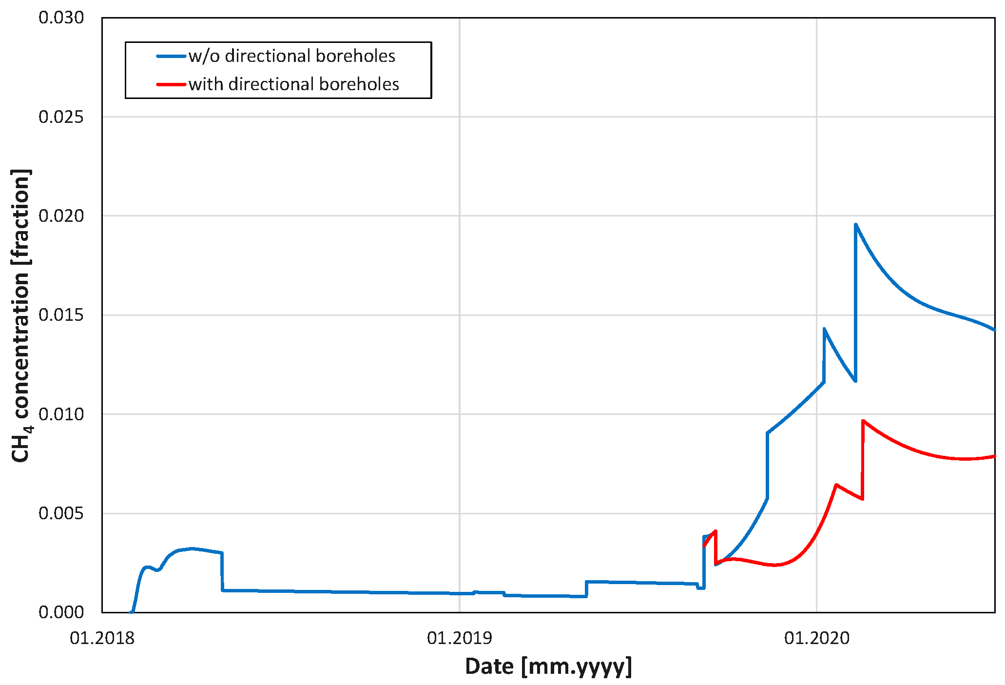
In particular, the comparison of methane concentration in the gas outflow to the ventilation system for the cases with and without the directional boreholes is shown in
Figure 27.
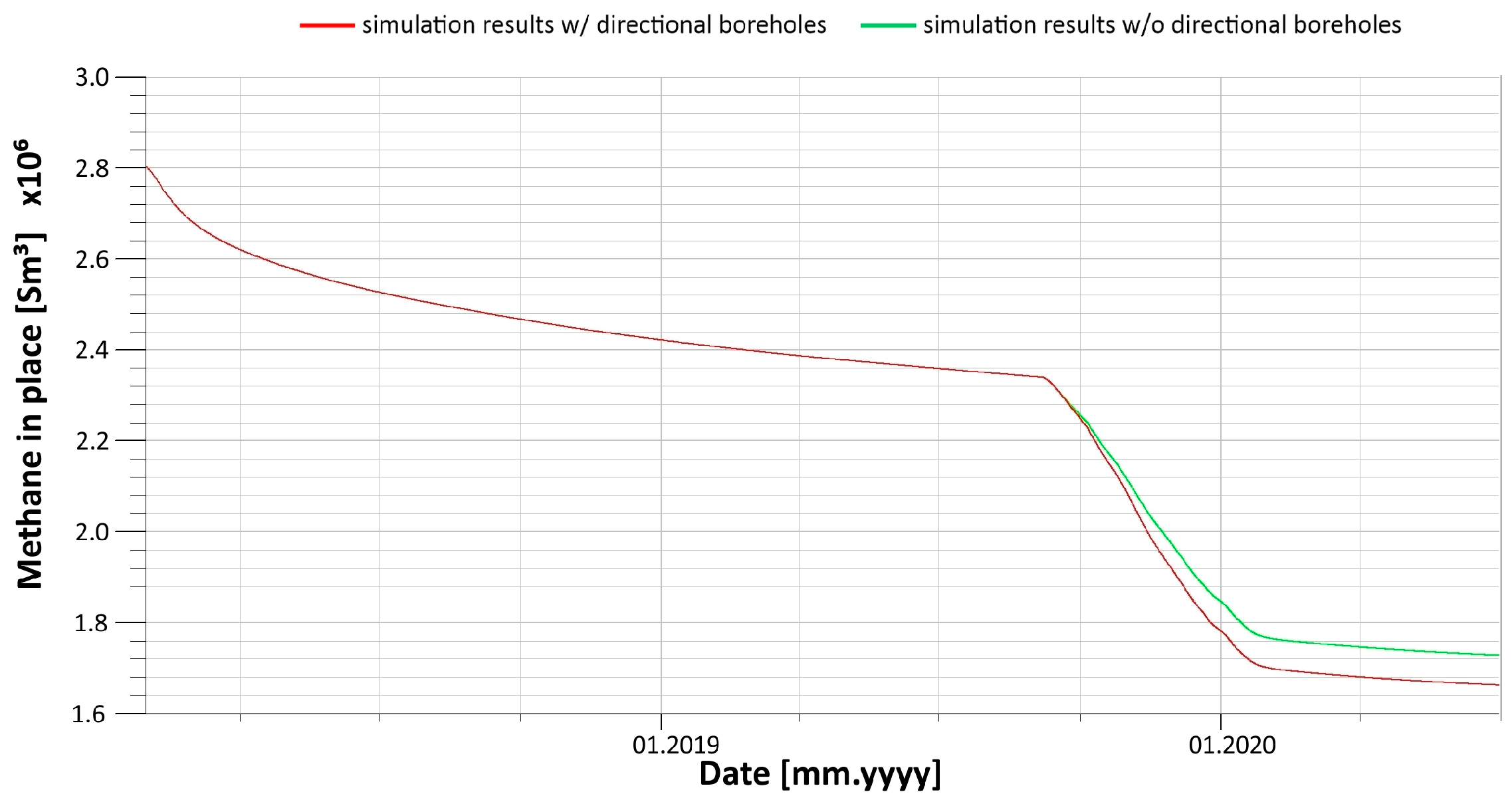
In addition, the results for the volume of methane left in the IC panel of the 501 coal seam are shown in
Figure 28 for both scenarios.
The distributions of methane adsorbed in coal matrices of the coal seams within the model are presented in
Figure 29. It includes four cross-sections for four rows defined as the mid-depth surface of the 501 coal seam, the vertical transverse cross-section along line A-A’, the vertical transverse cross-section along line B-B’, and the vertical longitudinal cross-section along line C-C’. Every set of four cross-sections corresponds to three situations (in three columns): the initial state before the panel excavation commencement, the final state after the panel excavation completion with directional boreholes, and the final state after the panel excavation completion without directional boreholes.
To summarise, the application of the long-reach directional boreholes proved the effectiveness of the analysed methane drainage method, as can be concluded from all the results presented above. In particular, the method significantly (by 52%) decreased the methane concentration in the ventilation gas (
Figure 26) and remarkably reduced the methane content in the coal matrix of the analysed coal seam (
Figure 28).
10. Sensitivity Analysis
The results of methane drainage from the analysed coal seam were dependent on various parameters, including the geological parameters of the structure. Multiple simulations of the coal excavation process, accompanied by the studied methane drainage strategy, provided the data required for the appropriate sensitivity analysis. Below, its results are presented for the basic parameters, including
- −
two parameters characterising the methane adsorption/desorption isotherm in the coal matrix—the asymptotic concentration, C0, and the characteristic pressure, P0, of the standard Langmuir isotherm;
- −
the overall amplitude of the rock transmissibility factors, T/T0, due to geomechanical elastic perturbations;
- −
the effective amplitude of the coal transmissibility multiplicative factor, Tc/Tc0, due to geomechanical inelastic and failure-type perturbations;
- −
uncertainty of the original porosity, ϕ, vertical permeability, kz, and horizontal permeabilities, kx, ky,+;
- −
the matrix–fracture coupling coefficient, σ, in the coal seams;
- −
the gas diffusion coefficient, D, for the methane migration from the coal matrix to coal fractures;
- −
the residual gas saturation, Sgcr, in the coal fractures.
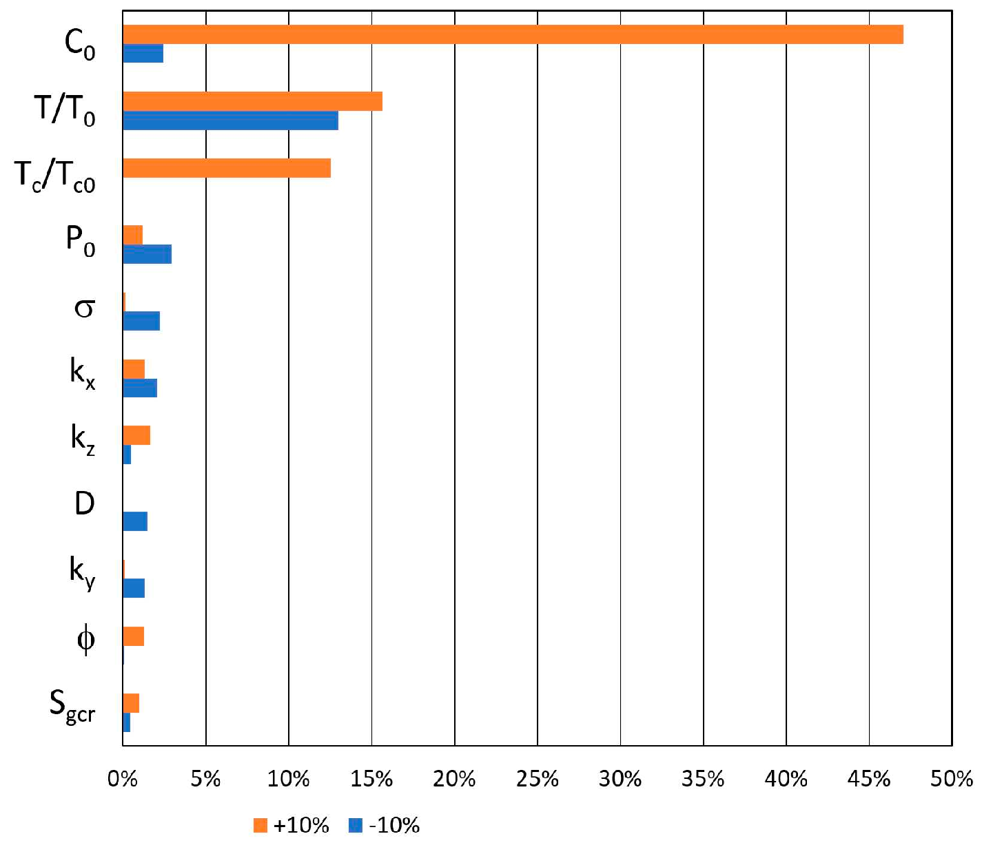
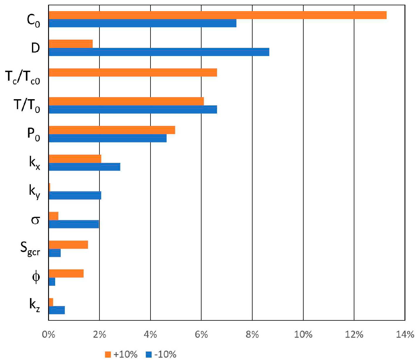
The influence of the above parameters for their relative modifications by ±10% upon four significant methane drainage effectiveness criteria is shown as tornado diagrams in
Figure 30 and
Figure 31 for the total gas and methane drainage by directional drainage boreholes, respectively.
As far as the total gas drainage by the directional drainage boreholes (
Figure 30) is concerned, the prevailing parameters are those determining the amount of adsorbed methane, namely the asymptotic concentration, C
0, and, to a lesser extent, the characteristic pressure, P
0, of the standard Langmuir isotherm. The other dominant parameters are the overall amplitude of the rock transmissibility factors, T/T
0, due to geomechanical elastic perturbations and the effective amplitude of the coal transmissibility multiplicative factor, T
c/T
c0, due to geomechanical inelastic and failure-type perturbations. Regarding the total methane drainage by the directional drainage boreholes (
Figure 31), it is primarily sensitive to the above four parameters and to the gas diffusion coefficient, D, for the methane migration from the coal matrix to coal fractures.
It is worth noting that the results of the sensitivity analysis show asymmetry between positive and negative variations of the key simulation results with respect to some parameters. The most probable reason for this behaviour is a non-linear correlation between the parameters and the results. Nevertheless, the relative significance of various parameters, as discussed above, is valid and can be treated as reliable. Hence, this observation does not affect the main conclusions stated below and cannot reduce the practical values of the presented sensitivity analysis.
Based on the sensitivity analysis results presented above, the following summary remarks concerning the total volume of methane drainage by the directional boreholes may be formulated.
- −
It is proportional to the original methane reserves adsorbed in the coal matrix—parameter C0 of the adsorption isotherm.
- −
It is also proportional to the methane volume available for the drainage at the effective pressure in the coal matrix—parameter P0 of the adsorption isotherm.
- −
It increases with the diffusive properties of the coal matrix—diffusion coefficient D of the coal matrix.
- −
It increases with the effective transmissibility coefficients of the coal matrix due to geomechanical perturbations.
- −
It also increases with the effective transmissibility coefficients of the clastic rocks neighbouring the coal seam.
Based on our analysis, the following conclusions have been drawn regarding the estimates of methane available for the drainage process and the corresponding drainage requirements:
- −
the reserves of methane adsorbed in the coal matrix, as well as the degree of its desorption at a given drainage pressure, must be determined through the identification and parametrisation of the adsorption isotherm,
- −
the significance of the diffusion transport properties of the coal matrix must be ascertained to accurately estimate the effective migration of methane from the coal matrix to the coal cleats,
- −
the detailed geomechanical characterisation of both the coal matrix and the surrounding clastic rocks must be acknowledged to assess the modification of their geomechanical state—specifically, the distributions of stress and strain—resulting from pressure variations,
- −
the correlation between the modified geomechanical state and the transport properties—namely, effective transmissibilities and diffusion coefficients—of the coal and clastic rocks needs to be established.
All the above parameters are of a geological and geomechanical type and should be analysed before the commencement of the coal excavation process and implementation of the method of methane drainage and its operation parameters. The influence of the latter on the effectiveness of the methane drainage process is presented in the next chapter.
11. Drainage Process Optimisation
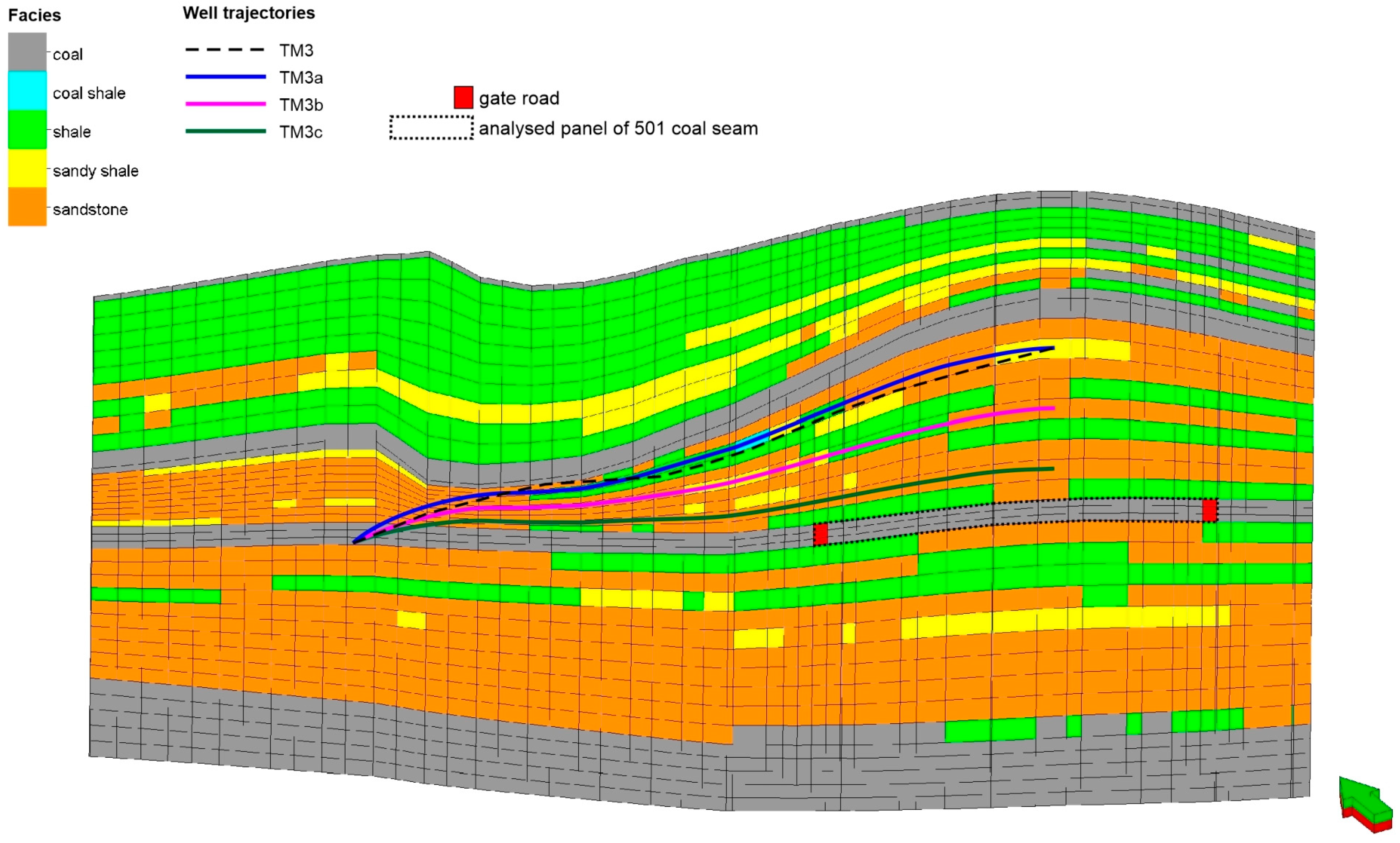
The calibrated model of the analysed carbon seam and the reliable simulations of its excavation process, accompanied by methane drainage, provide an opportunity to optimise the proposed strategy of methane drainage by a set of directional boreholes. According to practical aspects of the analysed underground long-reach directional drilling technology, the details of the directional borehole trajectories and their completion are the most significant and controllable. Among several parameters describing borehole trajectories, the most significant ones seem to be their depths and separation. Below, the results of the trajectory depths optimisation analysis are presented first. The total amount of methane drained by the directional boreholes and the total recovery of methane originally present in the excavated panel of the coal seam are selected as the basic criteria for the effectiveness of the analysed methane drainage method.
Two groups of different scenarios of directional borehole trajectories were considered. The first one included the original trajectories modified for their depth relative to the IC panel of the 501 coal seam, while they preserved their original localisation in the x-y plane. As an example,
Figure 32 presents the modifications of the original trajectory of the borehole TM3 denoted TM3a, TM3b, and TM3c for the alternative depths realised in Scenario 1a, Scenario 1b, and Scenario 1c, respectively. Analogous modifications of the other directional borehole trajectories were applied to the above scenarios. The most significant simulation results of Scenarios 1a, 1b, 1c, and the original are presented in
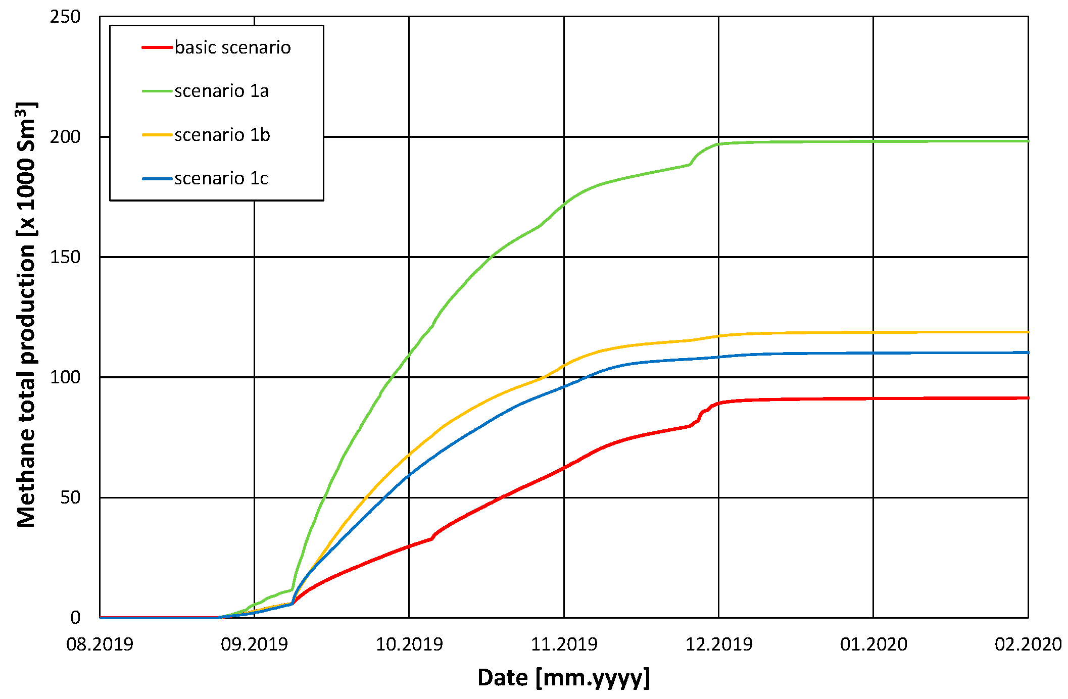
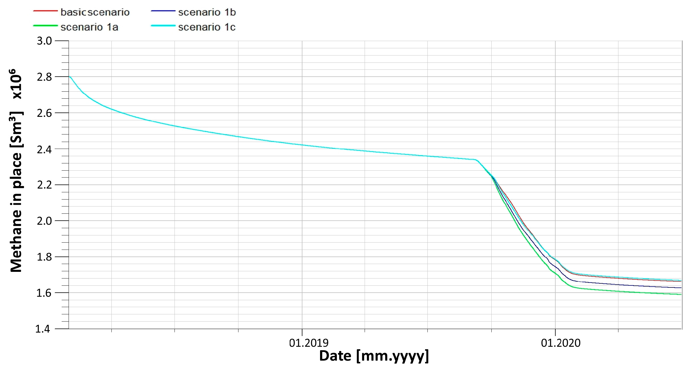
Figure 33 and
Figure 34 in terms of the total methane production by the directional boreholes from the analysed panel and the methane remaining in place of that panel vs. time, respectively.
Simulation results of those scenarios may be summarised by the following conclusion: the closer the trajectories to the excavated coal seam, the higher the degree of methane recovered from the seam within the IC panel. The additional recovery in terms of total methane production may exceed 200% (
Figure 33).
The other significant parameter describing borehole trajectories is their separation scheme. The corresponding group of analysed scenarios, denoted 2a, 2b, and 2c, included borehole trajectories covering the excavated panel with a horizontally uniform scheme. These scenarios differed in the depth of the trajectories in comparison with the previous group.
The simulation results of Scenarios 2a, 2b, 2c, and the original one are presented in
Figure 35 and
Figure 36 in terms of the total methane production by the directional boreholes from the IC panel of the 501 coal seam and the methane remaining in place of that panel vs. time, respectively.
Similar to the previous group of scenarios, the closer the trajectories to the 501 seam, the larger the methane total production (
Figure 35) and the higher the recovery (
Figure 36) of the methane originally adsorbed in the analysed panel. It is worth noting that the results of the latter group of Scenarios 2a, 2b, and 2c are systematically more advantageous than those of the first group. This result is caused by the difference in the total length of directional borehole completions draining methane from the analysed panel. This length equals 476 m for Scenarios 1a, 1b, and 1c vs. 304 m for Scenarios 2a, 2b, and 2c.
However, it should be noted that there is another factor limiting that conclusion, namely, wellbore instability. Openings of the directional boreholes may be partially located in the coal seam, and they usually pass through mudstone and sandstone when entering the fracture zone. Due to the relatively large diameters of the boreholes, they are susceptible to loss of stability, resulting in their deformation and collapse. Therefore, the stability of the long-reach directional boreholes may directly affect their drainage performance. The influencing factors of borehole stability mainly include rock strength, drainage pressure, stress and strain, burial depth, lateral pressure coefficient, and anisotropic permeability, as indicated by [
85,
86,
87,
88].
In particular, X. Yao et al. [
85] constructed a local model of a long drilling borehole through the soft coal seam of Dingji Coal Mine, China and performed numerical simulations to obtain stress and displacement fields and plastic failure zone. They concluded that the stress concentration of the surrounding rock becomes higher with the increase in the side pressure coefficient. For the same reason, the displacement of drilling increases and the radius of the plastic zone decreases. Moreover, the drilling becomes more unstable with this variation in the side pressure coefficient. E. Karatela and A. Taheri [
86] constructed a three-dimensional hydro-mechanical model of a borehole in fractured rock mass. They simulated overbalanced drilling conditions and validated the model against log measurements of the caliper log and found the strength of rock to be a governing factor in controlling the borehole stability. In addition, they observed that high mud flow rates as well as high pore pressure increased the instability around the borehole. Z. Wang et al. [
87] performed studies on the instability of directional boreholes localized on coal seam roofs. They adopted the geological and geomechanical conditions of a coal seam in the Tingnan Coal Mine, Shaanxi Province, China. They performed numerical simulations and obtained stress, strain, and plastic deformations of the rocks surrounding the boreholes with different diameters. The simulation results showed that the borehole stability depended on rock type. It was lower for coal and mudstone than for sandstone. They also concluded that the larger the borehole diameter, the lower the borehole stability. According to the authors, their research results provided reliable technical support for the protection of directional boreholes on coal seam roofs. X-B Zhang et al. [
88] studied the dependence of gas extraction in deep mining soft coal seams on deformation and instability of drainage boreholes. They analysed deformation instability mechanisms and dynamic changes of borehole suction pressures for three deformation instability modes: (1) complete holes, (2) collapse holes, and (3) plug holes. The resultant suction pressure loss of the drainage system was found to be very small for case (1) and much bigger in case (2). In case (3), a continuous medium formed at the plug segment, and the plug segment drainage pressure turned into coal bed gas pressure. According to the authors, their study provided important guidelines for improving gas drainage and effectively preventing gas disasters.
From the above results, it follows that to study directional borehole stability, it is necessary to use a high-resolution and appropriate (non-cartesian) symmetric type of numerical model of all the borehole vicinities combined with a large-scale model. This kind of study goes beyond the scope of the research presented in this paper.
12. Summary and Conclusions
The studies reported in this paper address specific issues referring to long-reach directional drilling (LRDD) for methane drainage purposes; such issues have not been covered by other research activities in the area of methane emission in coal mines. These innovative studies are based on a comprehensive numerical modelling approach. They include the following tasks: (i) the construction of structural and parametric geological models, (ii) the construction of dynamic simulation models of a selected coal mine structure, (iii) the implementation of the initial conditions of the structure, (iv) the analysis of the geomechanical effects of various types and regions of occurrence, (v) the implementation of the correlation between the geomechanical state of the rocks and their transport properties, (vi) the performance of the effectively coupled geomechanical and fluid flow simulations, (vii) the calibration of the models based on historical coal seam exploitation and methane drainage data, (viii) the analysis of the effectiveness of methane drainage by the proposed long-reach directional drilling technology, (ix) sensitivity analysis of the drainage results to geological and geomechanical properties of the rocks, and (x) the limited optimization of the drainage process with respect to the technological and operational parameters of the proposed strategy.
The results of the above simulation studies lead to the following main conclusion: the effectiveness of the analysed methane drainage method with the use of long-reach directional drilling is strongly confirmed and, in the analysed case, results in a 52% decrease in the methane content in the ventilation gas. It also leads to a concomitant reduction of the methane content in the coal matrix of the excavated coal seam. Thus, the studies, whose results are presented and discussed above, provide evidence for numerical modelling methods with coupled reservoir fluid flow simulations and geomechanical simulations to as a very useful and feasible approach to analysing the very specific method of methane drainage employing underground long-reach directional drilling technology.
In addition to the assessment of the method’s effectiveness, this approach allows one to quantitatively determine the sensitivity of the methane drainage to both geological and geomechanical parameters (reserves of methane adsorbed in the coal matrix, degree of desorption, diffusive migration of methane from coal matrix to cleats, etc.) and thus also allows one to estimate the uncertainty and risks of the analysed method. Moreover, practical optimisation of the analysed method is feasible for the application of the approach used in this study by the proper selection of operational parameters, such as trajectories and completions of drainage boreholes.
It is worth noting that an analysis of the possible risks or limitations of the proposed method is provided in the report of a previous project [
89], where the studies reported in this paper were performed. Particular issues concerning environmental risk assessment in coal mining with the proposed methane degassing approach are presented in [
90].
In general, to achieve an analogous conclusion for any specific case of multi-seam coal systems, it is necessary to apply a similar approach taking into account all the key phenomena determining the complete gas migration route, including gas desorption from coal matrix, its diffusion to coal cleats, and viscous multiphase flow through porous and fractured media of coal multi-seams and other clastic rocks. Moreover, the variations in the geomechanical states of all the rocks present in the studied system have to be taken into account along the fluid flow, as they may significantly influence rock transport properties and thus reciprocally affect the flow.
To this aim, complex models describing both the transport properties of an appropriate fluid–rock system and the mechanical properties of both its separate components have to be developed to be used in coupled simulations of the key phenomena; they can also be used to reliably assess the effectiveness of various methane drainage methods, as shown in these studies, in the particular case of underground long-reach directional drilling method.
Only then can one resolve the fundamental question of the method’s feasibility, the sensitivity of the methane drainage effects to both geological and geomechanical parameters, and the method’s uncertainty and application risks, as well as practical optimisation with respect to the method’s operational parameters.


 ,
, 


