
Optimal Split Ratio in Double-Stator Permanent-Magnet Motors Considering Loss Limitations for Robot Joint Applications


Abstract
1. Introduction
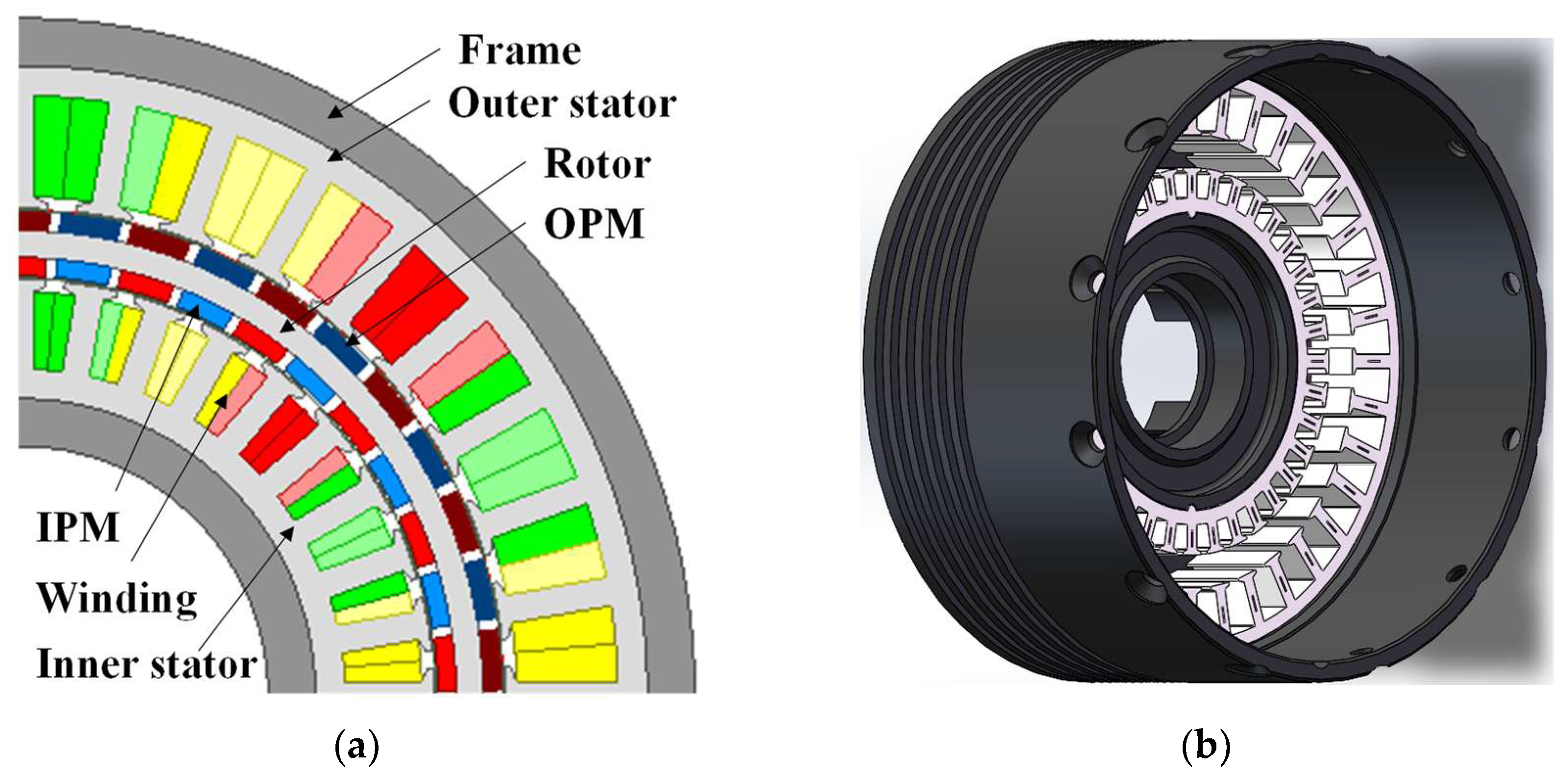
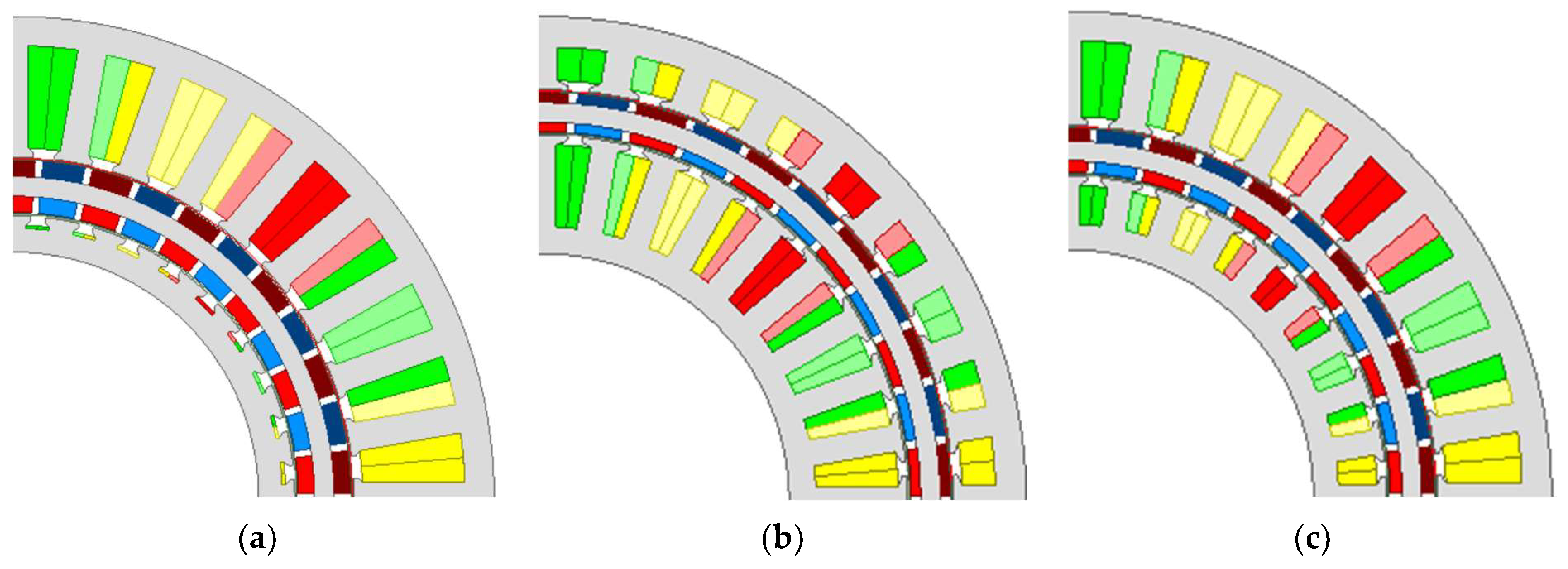
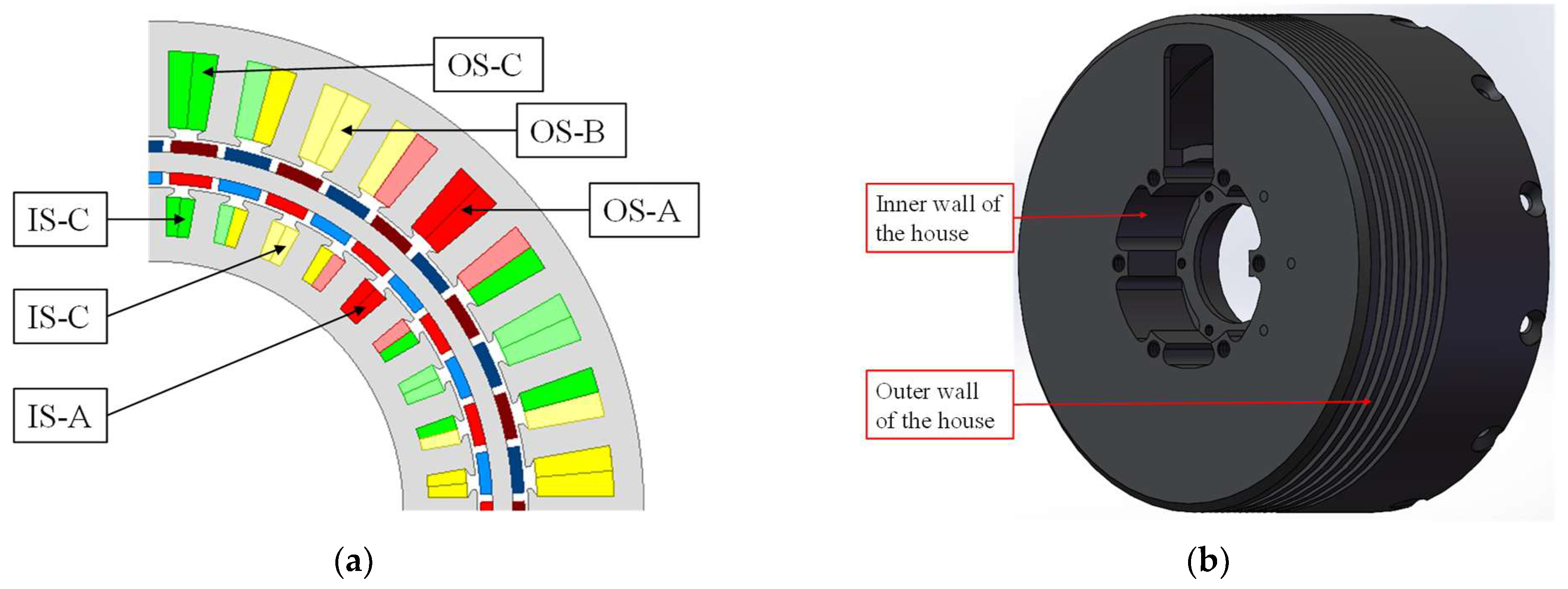
2. Motor Topology
3. Optimal Split Ratio
3.1. Loss Limitation
3.2. Torque Calculation
3.3. Optimal Results
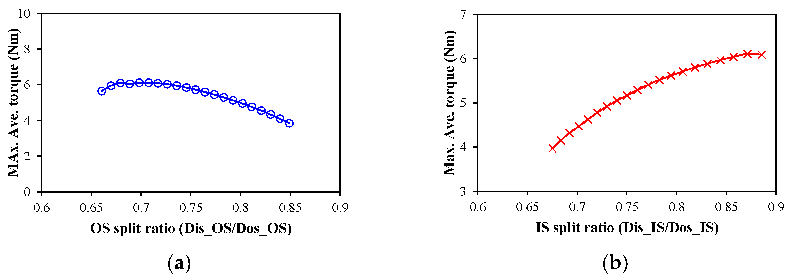
3.3.1. Torque Considering Outer Stator Loss Limitation Only
3.3.2. Torque Considering Inner Stator Loss Limitation Only
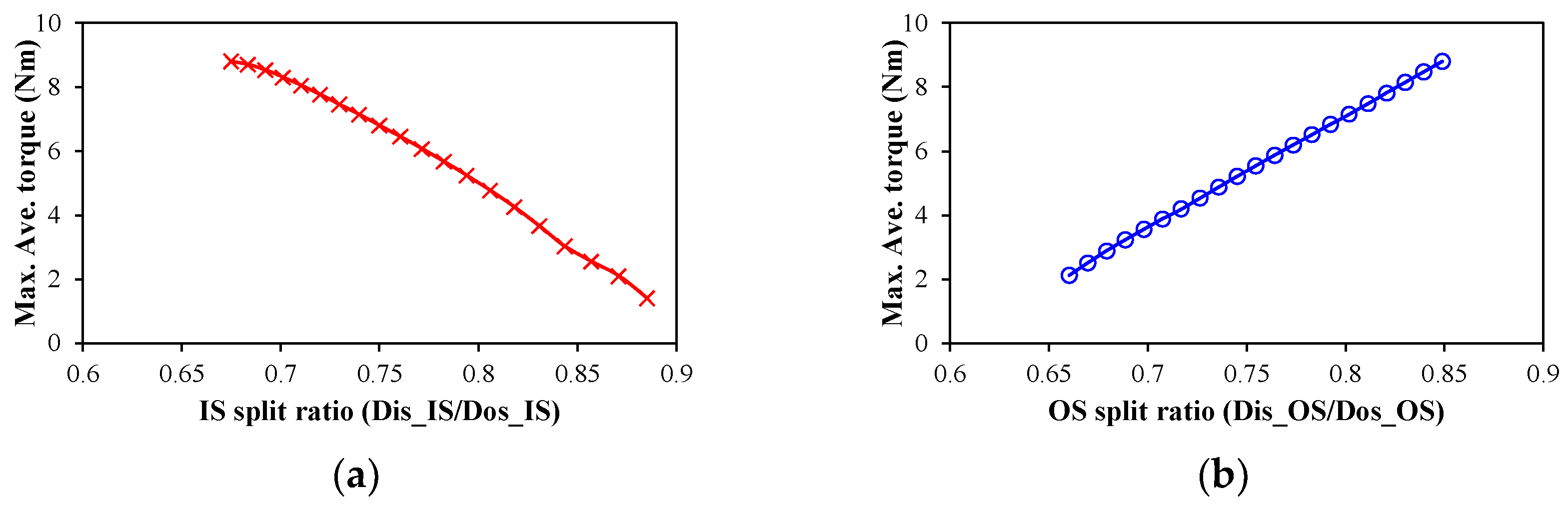
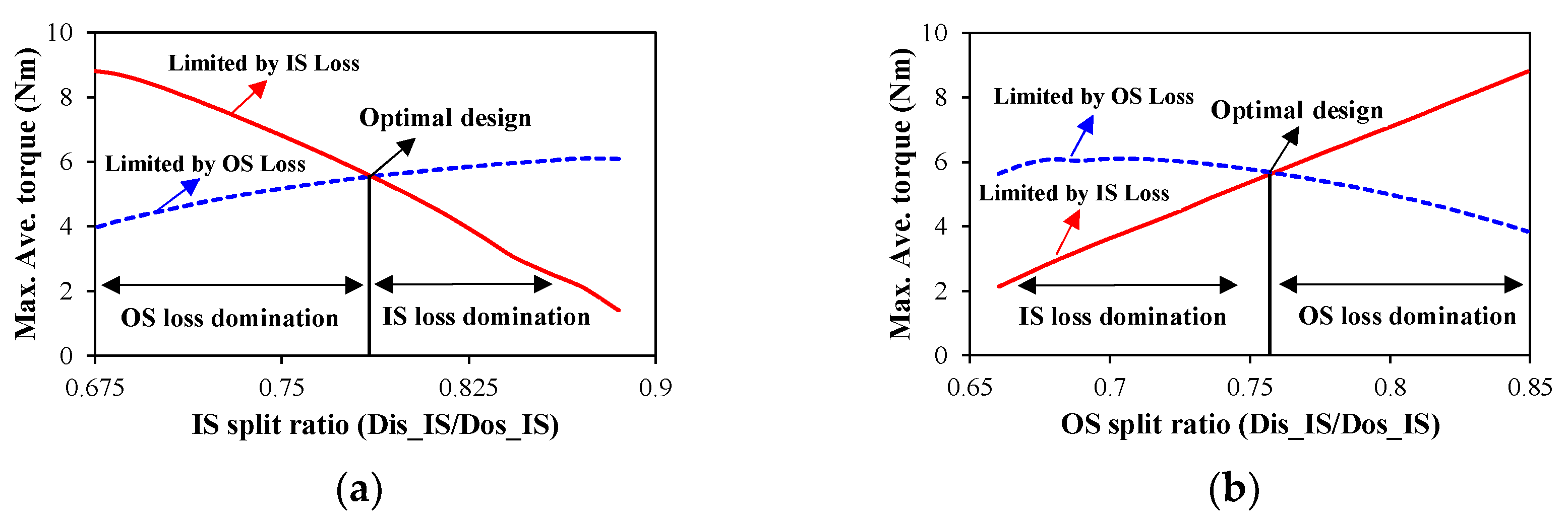
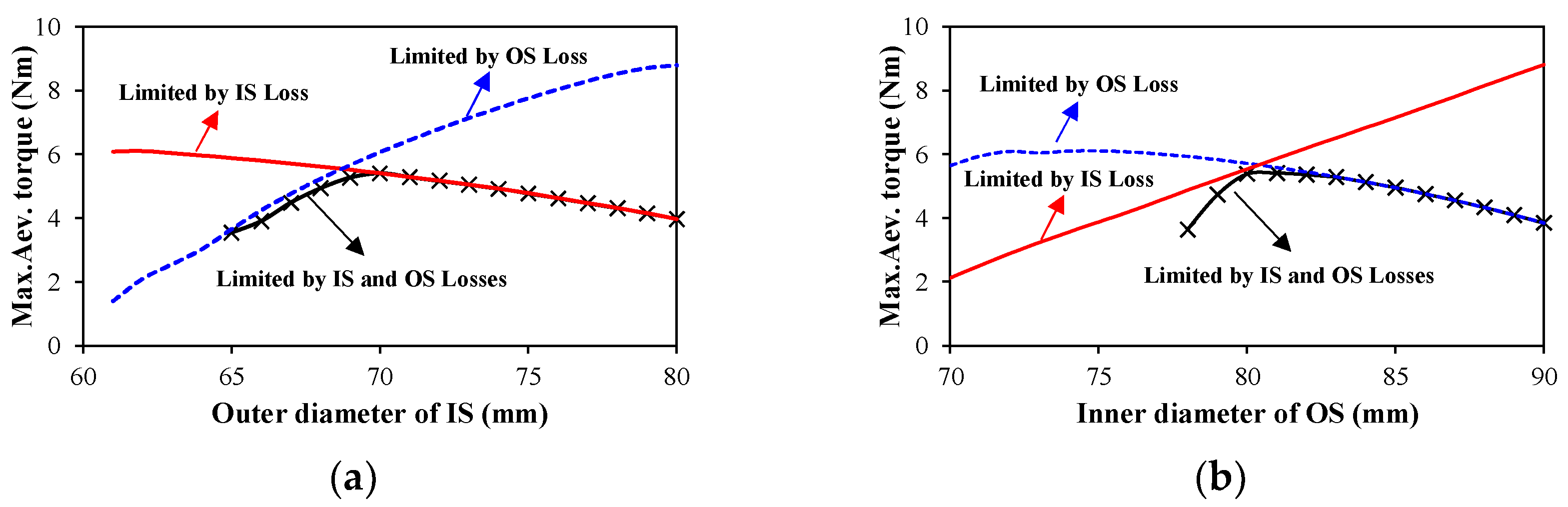
3.3.3. Torque Considering Outer and Inner Stator Loss Limitations
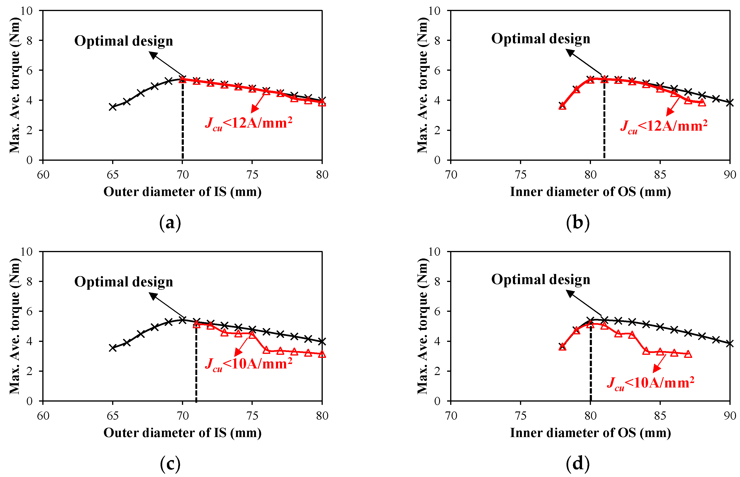
3.3.4. Torque Considering Current Density
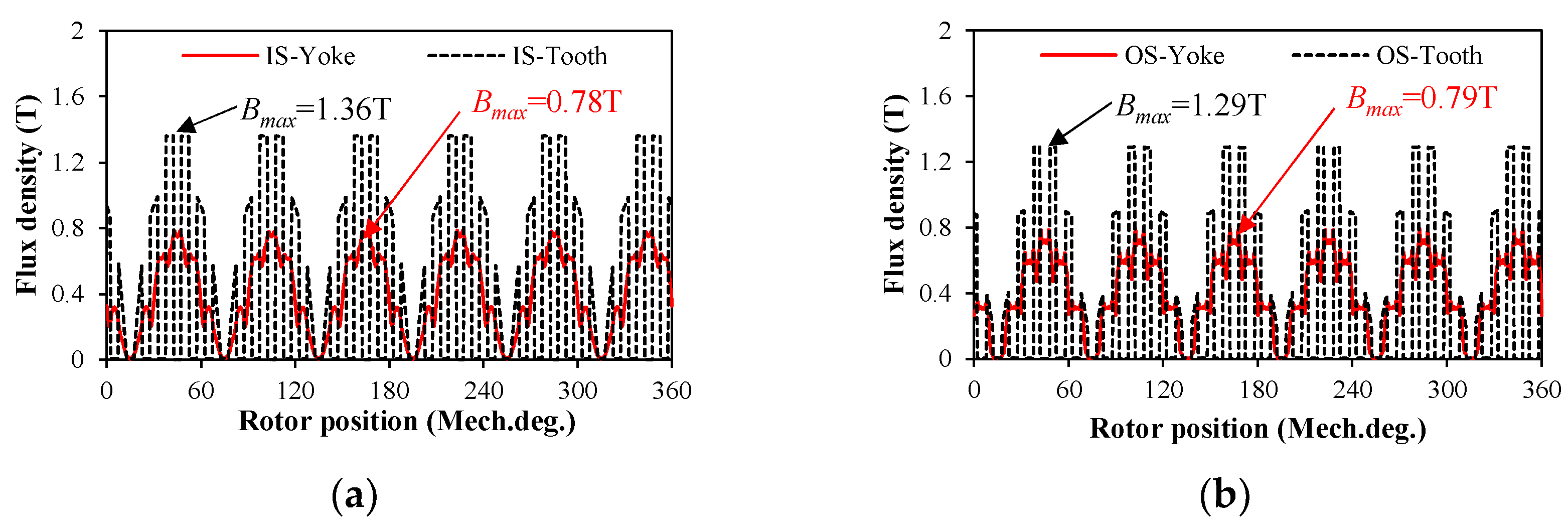
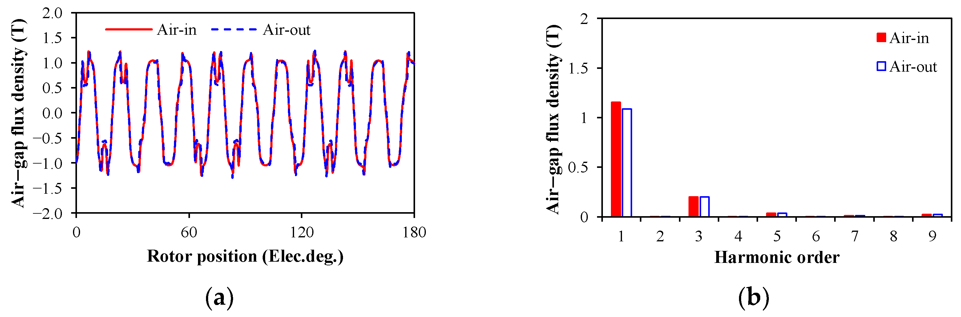
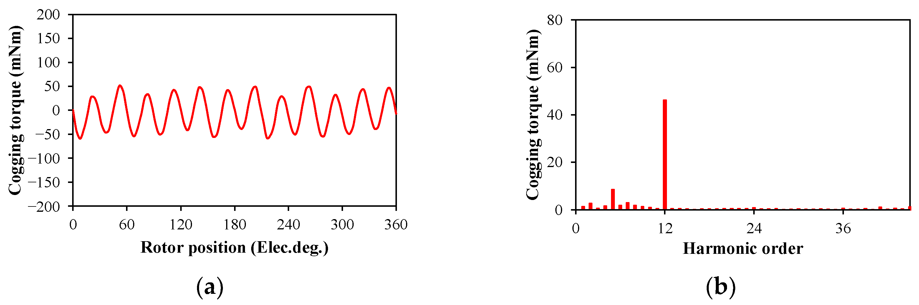
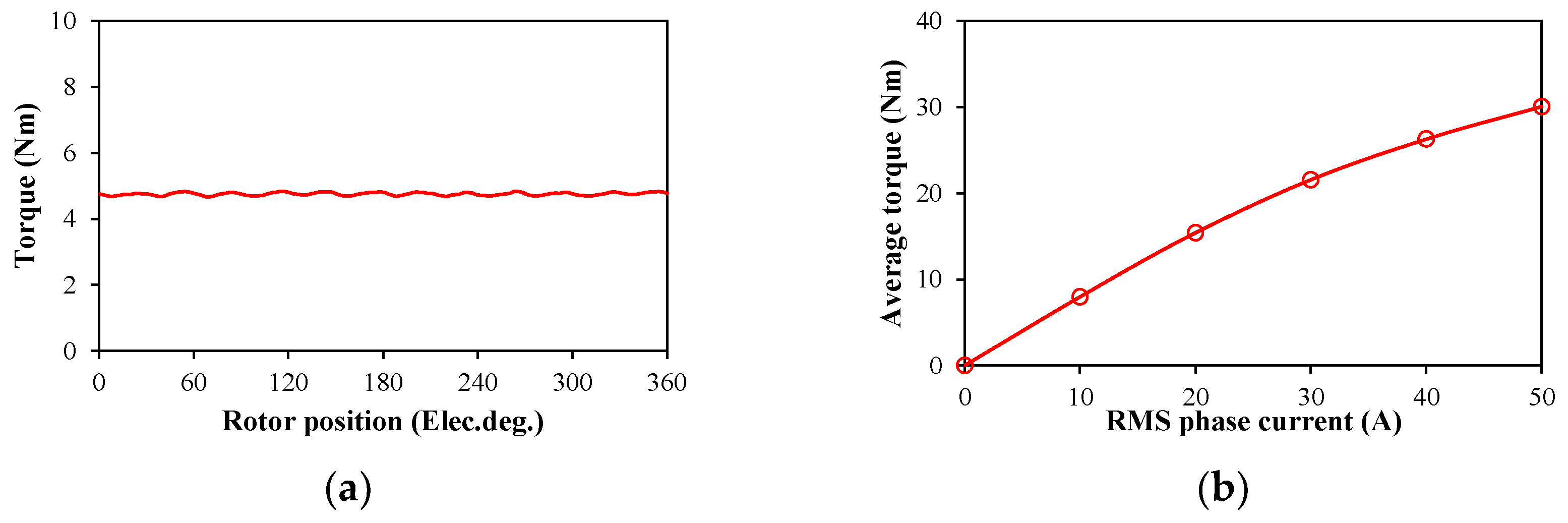
4. Electromagnetic Performance
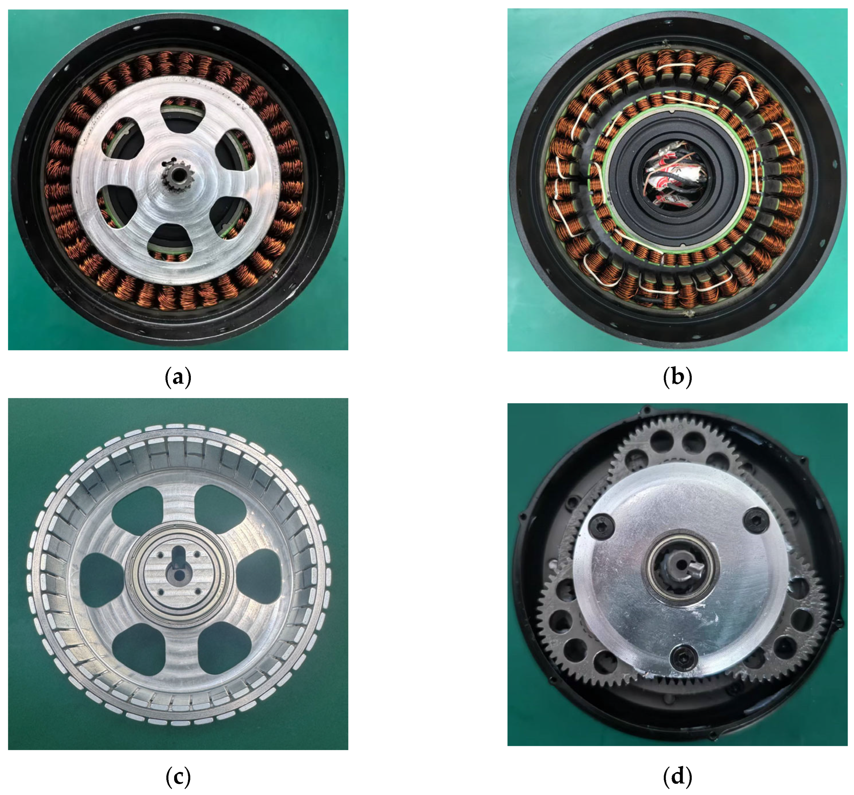
5. Experimental Validation
6. Conclusions
Author Contributions
Funding
Data Availability Statement
Conflicts of Interest
References
- Levy, D. Analysis of a double-stator induction machine used for a variable-speed/constant-frequency small-scale hydro/wind electric power generator. Electr. Power Syst. Res. 1986, 11, 205–223. [Google Scholar] [CrossRef]
- Niu, S.; Chau, K.T.; Jiang, J.Z.; Liu, C. Design and control of a new double-stator cup-rotor permanent-magnet machine for wind power generation. IEEE Trans. Magn. 2007, 43, 2501–2503. [Google Scholar] [CrossRef]
- Liu, X.P.; Lin, H.Y.; Yang, C.F. 3-D FEA and experiment study of novel dual-stator hybrid excited wind generator. Proc. CSEE 2008, 20, 142–146. [Google Scholar]
- Welburn, R. Ultra high torque motor system for direct drive robotics. In Applications for Today, Proceedings of the Robots 8: Conference Proceedings, Detroit, MI, USA, 4–7 June 1984; Robotics International of SME: Dearborn, MI, USA, 1984. [Google Scholar]
- Chai, F.; Xia, J.; Guo, B.; Cheng, S.K.; Zhang, J.G. Double-Stator Permanent Magnet Synchronous in-Wheel Motor for Hybrid Electric Drive System. IEEE Trans. Magn. 2009, 45, 278–281. [Google Scholar] [CrossRef]
- Zhao, Y.; Huang, W.; Jiang, W.; Lin, X.; Dong, D. Optimal design of double stator permanent magnet motors used in electric vehicle. In Proceedings of the 22nd International Conference on Electrical Machines and Systems (ICEMS), Harbin, China, 11–14 August 2019. [Google Scholar]
- Fan, D.; Quan, L.; Zhu, X.; Xiang, Z.; Que, H. Airgap-harmonic-based multilevel design and optimization of a double-stator flux-modulated permanent-magnet motor. IEEE Trans. Ind. Electron. 2021, 68, 10534–10545. [Google Scholar] [CrossRef]
- Wang, H.; Yan, X.; Huang, S.; Sui, T. Design and torque analysis of dual-stator permanent magnet motor for electric motorcycle. Micromotors 2011, 4, 7–10. [Google Scholar]
- Sugiura, K.; Noguchi, T. Ultra-High-Power-Rate PM motor with double stator structure. In Proceedings of the IEEE Transportation Electrification Conference and Expo, Asia-Pacific (ITEC Asia-Pacific), Chiang Mai, Thailand, 28 November–1 December 2023. [Google Scholar]
- Zheng, B.; Yan, D.; Song, P.; Zhang, Z.; Yan, Y. Optimal design of dual-stator permanent magnet synchronous motors under multiple working conditions. Electric Drive 2025, 1–7. [Google Scholar] [CrossRef]
- Kandil, A.; Hou, L.; Sharaf, M.; Arafa, A.A. Configuration angle effect on the control process of an oscillatory rotor in 8-pole active magnetic bearings. AIMS Math. 2024, 9, 12928–12963. [Google Scholar] [CrossRef]
- Li, R.; Xu, J.; Sun, X.; Chen, J.; Zhang, C. Design of Double Stator Permanent Magnet Synchronous Motor for Robot Joint. Small Spec. Electr. Mach. 2021, 49, 14–18. [Google Scholar]
- He, T.; Liang, D.; Tian, J.; Li, W.; Zhu, Z.Q. Comparative study of permanent magnet synchronous motors with single and double stators for robot joint applications. In Proceedings of the 3th International Conference on Sustainable Mobility Applications, Renewables and Technology (SMART), Dubai, United Arab Emirates, 22–24 November 2024. [Google Scholar]
- Hesmondhalgh, D.E.; Tipping, D.; Amrani, M. Design and construction of a high-speed high-performance direct drive handpiece. IEE Proc. 1987, 134, 286–296. [Google Scholar] [CrossRef]
- Chaaban, F.B. Determination of the optimum rotor/stator diameter ratio of permanent magnet machines. Electr. Mach. Power Syst. 1993, 01, 521–531. [Google Scholar] [CrossRef]
- Pang, Y.; Zhu, Z.; Howe, D. Howe. Analytical determination of optimal split ratio for permanent magnet brushless motors. IEE Proc. Electr. Power Appl. 2006, 153, 7–13. [Google Scholar] [CrossRef]
- Shen, Y.; Zhu, Z.Q. Analytical prediction of optimal split ratio for fractional-slot external rotor PM brushless machines. IEEE Trans. Magn. 2011, 47, 4187–4190. [Google Scholar] [CrossRef]
- Chu, W.; Zhu, Z. Optimal split ratio and torque comparison of surface-mounted permanent magnet machines having inner or outer rotor. In Proceedings of the 6th IET International Conference on Power Electronics, Machines and Drives, Bristol, UK, 27–29 March 2012. [Google Scholar]
- Wu, L.J.; Zhu, Z.Q.; Chen, J.T.; Xia, Z.P.; Jewell, G.W. Optimal split ratio in fractional-slot interior permanent-magnet machines with non-overlapping windings. IEEE Trans. Magn. 2009, 46, 1235–1242. [Google Scholar] [CrossRef]
- Chai, F. Fundamental Research on Double-Stator Integrated Starter Generator for Hybrid Electric Vehicle; Harbin Institute of Technology: Harbin, China, 2003. [Google Scholar]
- Chai, F.; Xia, J.; Gong, H.L.; Guo, B.; Cheng, S.K. Torque analysis of double-stator permanent magnet synchronous for hybrid electric vehicle. In Proceedings of IEEE Vehicle Power and Propulsion Conference, Harbin, China, 3–5 September 2008. [Google Scholar]
- Zhang, D. Design and Analysis of a Novel Double-Stator Permanent Magnet Machine. Ph.D. Thesis, Shanghai University, Shanghai, China, 2007. [Google Scholar]
- Wang, Y.B.; Cheng, M.; Fan, Y.; Chau, K.T. Design and analysis of double-stator permanent magnet brushless motor for hybrid electric vehicles. In Proceedings of International Conference on Electrical Machines and Systems, Wuhan, China, 17–20 October 2008. [Google Scholar]
- Wang, Y.B.; Cheng, M.; Hua, W. Analysis and optimization of split ratio for double-stator permanent magnet brushless machine. Proc. CSEE 2010, 30, 62–67. [Google Scholar]
- Yang, S.; Zhang, F.; Zhang, Z.; Liu, H. Design of double stator permanent magnet synchronous motor with low speed large torque. In Proceedings of IEEE Student Conference on Electric Machines and Systems, Huzhou, China, 14–16 December 2018. [Google Scholar]
- Bianchi, N.; Bolognani, S.; Luise, F. Potentials and limits of high-speed PM motors. IEEE Trans. Ind. Appl. 2004, 40, 1570–1578. [Google Scholar] [CrossRef]
- Levi, E. Polyphase Motors; Wiley: New York, NY, USA, 1984. [Google Scholar]


| Parameter | Data | Parameter | Data |
|---|---|---|---|
| Outer diameter of OS, mm | 106 | Rated speed, r/min | 1200 |
| Inner diameter of IS, mm | 54 | Stator active length, mm | 20 |
| Air-gap length, mm | 0.4 | Pole arc coefficient | 0.84 |
| Parameter | OS | IS |
|---|---|---|
| Heat transfer coefficient, W/(m2·K) | 50 | 25 |
| Maximum winding temperature rise, K | 100 | 100 |
| Stator outer/inner diameter, mm | 106 | 54 |
| Stator active length, mm | 20 | 20 |
| Loss limitation, W | 33.28 | 8.48 |
| Kloss = Loss_OS/Loss_IS | 3.51/1 | |
| Parameter | Data | Parameter | Data |
|---|---|---|---|
| Outer diameter of OS (mm) | 106 | RMS phase current (A) | 5.93 |
| Inner diameter of OS (mm) | 81 | Outer/inner packing factor | 0.43/0.39 |
| Outer diameter of IS (mm) | 70 | Max. stator flux density (T) | 1.8 |
| Inner diameter of IS (mm) | 54 | Copper losses of OS (W) | 33.28 |
| Rotor yoke thickness (mm) | 2.2 | Copper losses of IS (W) | 8.05 |
| PM thickness (mm) | 1.25 | Current density of OS/IS (A/mm2) | 10.5/10.3 |
| Tooth width of OS (mm) | 3.21 | Torque_total (Nm) | 5.41 |
| Yoke thickness of OS (mm) | 3.21 | Torque_IS (IS/Total) (Nm) | 1.01 (18.67%) |
| Tooth width of IS (mm) | 2.77 | Torque_OS (OS/Total) (Nm) | 4.40 (81.33%) |
| Yoke thickness of IS (mm) | 2.77 | KT = Torque_OS/Torque_IS | 4.36/1 |
| Parameter | Measured | Predicted |
|---|---|---|
| Phase resistance of OS (Ω) | 0.273 | 0.315 |
| Phase resistance of IS (Ω) | 0.074 | 0.076 |
| Phase resistance (Ω) | 0.347 | 0.396 |
| Phase inductance of OS (μH) | 364.0 | 456.19 |
| Phase inductance of IS (μH) | 27.8 | 32.22 |
| Phase inductance (μH) | 391.8 | 488.41 |
Disclaimer/Publisher’s Note: The statements, opinions and data contained in all publications are solely those of the individual author(s) and contributor(s) and not of MDPI and/or the editor(s). MDPI and/or the editor(s) disclaim responsibility for any injury to people or property resulting from any ideas, methods, instructions or products referred to in the content. |
© 2025 by the authors. Licensee MDPI, Basel, Switzerland. This article is an open access article distributed under the terms and conditions of the Creative Commons Attribution (CC BY) license (https://creativecommons.org/licenses/by/4.0/).
Share and Cite
He, T.; Shen, Y.; Li, W.; Liang, D. Optimal Split Ratio in Double-Stator Permanent-Magnet Motors Considering Loss Limitations for Robot Joint Applications. Energies 2025, 18, 3594. https://doi.org/10.3390/en18143594
He T, Shen Y, Li W, Liang D. Optimal Split Ratio in Double-Stator Permanent-Magnet Motors Considering Loss Limitations for Robot Joint Applications. Energies. 2025; 18(14):3594. https://doi.org/10.3390/en18143594
Chicago/Turabian StyleHe, Tianran, Yang Shen, Wei Li, and Dawei Liang. 2025. "Optimal Split Ratio in Double-Stator Permanent-Magnet Motors Considering Loss Limitations for Robot Joint Applications" Energies 18, no. 14: 3594. https://doi.org/10.3390/en18143594
APA StyleHe, T., Shen, Y., Li, W., & Liang, D. (2025). Optimal Split Ratio in Double-Stator Permanent-Magnet Motors Considering Loss Limitations for Robot Joint Applications. Energies, 18(14), 3594. https://doi.org/10.3390/en18143594