Article

An Investigation of Channeling Identification for the Thermal Recovery Process of Horizontal Wells in Offshore Heavy Oil Reservoirs

1
State Key Laboratory of Offshore Oil Exploitation, Beijing 100028, China
2
CNOOC Research Institute Co., Ltd., Beijing 100028, China
3
State Key Laboratory of Petroleum Resources and Prospecting, China University of Petroleum (Beijing), Beijing 102249, China
*
Author to whom correspondence should be addressed.
Energies 2025, 18(13), 3450; https://doi.org/10.3390/en18133450
Submission received: 12 May 2025 / Revised: 10 June 2025 / Accepted: 13 June 2025 / Published: 30 June 2025

Abstract

The development of inter-well channeling pathways has become a major challenge restricting the effectiveness of the thermal recovery process for heavy oil reservoirs, which leads to non-uniform sweep and reduced oil recovery. This is especially true for the characteristics of the higher injection–production intensity in offshore operations, making the issue more prominent. In this study, a quick and widely applicable approach is proposed for channeling identification, utilizing the static reservoir parameters and injection–production performance. The results show that the cumulative injection–production pressure differential (CIPPD) over the cumulative water equivalent (CWE) exhibits a linear relationship when connectivity exists between the injection and production wells. Thereafter, the seepage resistance could be analyzed quantitatively by the slope of the linear relationship during the steam injection process. Simultaneously, a channeling identification chart could be obtained based on the data of injection–production performance, dividing the steam flooding process into three different stages, including the energy recharge zone, interference zone, and channeling zone. Then, the established channeling identification chart is applied to injection–production data from two typical wells in the Bohai oilfield. From the obtained channeling identification chart, it is shown that Well X1 exhibits no channeling, while Well X2 exhibited channeling in the late stage of the steam flooding process. These findings are validated against the field performance (i.e., the liquid rate, water cut, flowing temperature, and flowing pressure) to confirm the accuracy. The channeling identification approach in this paper provides a guide for operational adjustments to improve the effect of the thermal recovery process in the field.

1. Introduction

The global offshore heavy oil resources are primarily distributed in the Gulf of Mexico, the North Sea, the Mediterranean Sea, and the Congo Zatchi area. However, their development has predominantly relied upon cold production methods such as water flooding and chemical flooding, and few large-scale thermal recovery operations on offshore platforms have been reported [1,2,3,4]. The offshore heavy oil resources of China are mainly distributed in the Bohai Sea, where the reservoirs are primarily located with edge or bottom water. These reservoirs are usually characterized by their deep burial depth, high porosity and permeability, relatively thin pay zone, and strong heterogeneity [5,6,7]. Chinese offshore heavy oil resources have significant reserves, which constitute 46.4% of the total offshore proven geological reserves in China [5,8]. In contrast with onshore heavy oil reservoirs, the spatial constraints of production platforms necessitate the recovery process with less wells, larger well spacings, and higher productivity. Therefore, horizontal well technology is the most appropriate pattern to enhance offshore oil production [5,9,10,11,12]. In the recovery process of offshore heavy oil reservoirs, it presents unique challenges including the limited exploratory well data, difficulties in refined reservoir characterization, and high capital investment required. Therefore, reducing thermal recovery costs and improving economic viability are the top priorities for the thermal recovery process of offshore heavy oil reservoirs [5,13].
Conventional water flooding and chemical flooding processes have achieved a satisfactory production performance for common heavy oil reservoirs in the Bohai oilfield, especially for heavy oil with a viscosity of lower than 350 mPa·s. However, these processes demonstrate limited effectiveness in high-viscosity zones despite their substantial resource potential [14,15,16]. To achieve the effective recovery of offshore heavy oil reservoirs, enhancing the development performance of high-viscosity reservoirs has become a critical challenge. Since 2008, pilot tests of cyclic steam stimulation (CSS) and cyclic multicomponent thermal fluid stimulation (CMTFS) processes have been conducted in the NB35-2 reservoir and LD27-2 reservoir in the Bohai oilfield, demonstrating promising production performance [17]. However, as thermal recovery operations are performed, a channeling path can gradually form among wells (i.e., injected steam preferentially flows through these channeling paths to production wells), resulting in a non-uniform steam profile, low thermal efficiency, dramatically reduced oil production, and rapid water cut increase [18,19]. Especially for the reservoirs with significant heterogeneity, the injected steam preferentially enters along the dominant directions or high-permeability zones, and the challenge of channeling is more remarkable [20,21]. Therefore, to reduce development costs and improve field economic performance, the accurate and timely identification of channeling plays a critically important role in implementing effective profile control processes.
Currently, the reported methods of channeling identification in the world primarily include inter-well potential monitoring, tracer analysis, well testing data, machine learning, and production performance. He et al. determined the steam channels and wells requiring plugging operations with a potential monitor. Meanwhile, the accuracy was verified by combining with the well plugging operation in the field and comparative potential monitoring conducted before and after the plugging measures [22]. However, the inter-well potential monitoring process, which requires deployment of extensive electrode arrays, conflicts with the spatial constraints of offshore production platforms [23]. For offshore reservoirs with poorly characterized intel-well reservoir properties, Cao et al. conducted a fluorobenzoic acid tracer investigation in the field. They obtained the inter-well channeling features by quantitative analysis of the tracer breakthrough time, tracer concentration in the produced oil, breakthrough duration, and peak tracer concentration [24]. Although a tracer analysis can accurately identify channeling paths, this method requires extended test durations and incurs significant costs [25,26]. In addition, the pressure analysis is another approach for channeling identification. Based on the actual pressure fall-off test data of a polymer injection well from the B oilfield in the Bohai Sea, Zeng et al. determined the key parameters of channels with the established well test interpretation model [27]. Nevertheless, the well test interpretation method requires complex operation procedures, and an observation well or production shut-in for testing is necessary in most cases, interfering with normal production operations in offshore oilfields [28,29]. With the rapid development of artificial intelligence (AI) and high-performance computing (HPC), the machine-learning-based approach provides an effective alternative for reservoir seepage simulation [30,31]. Wang established a prediction model for steam channeling with the deep learning sequence-to-sequence structure and long short-term memory neural network used [32]. Song et al. proposed the steam channeling prediction models using the random forest, support vector machine (SVM), neural network, and XGBoost algorithms, respectively, and obtained the steam channeling pathway distributions [33]. Jeong et al. presented the optimal operation strategy of the Fast-SAGD process considering steam channeling and vapor interference among steam chambers, in which the energetic efficiency of Fast-SAGD was optimized based on an artificial neural network (ANN) [34]. Nonetheless, these machine-learning-based methods significantly rely on the extensive high-fidelity training data and employed algorithm. In the field, the production performance can be easily obtained and effectively reflects inter-well connectivity. Meanwhile, using production performance can provide a more economical approach to investigate the channeling while allowing for the quantitative characterization of the channeling pathways [19]. Zheng et al. developed a model to calculate the steam channel volumes with the variations in temperature and pressure being considered [35]. According to the field performance data, Wu et al. obtained a multi-index forecast model for steam breakthrough by the overall optimal sequence degrees matrix [36]. Zhao et al. established a two-parameter variable weight objective function to represent the dynamic effects of inter-well connectivity on the liquid production and bottom-hole pressure [19]. Most reported identification methods for channeling with production performance focus on the vertical wells, with few attempts at channeling identification in horizontal wells. Furthermore, considering the unique development characteristics and operational constraints of offshore heavy oilfields, the conventional dynamic analysis method designed for offshore oilfields with small well spacings is inapplicable for channeling identification with offshore large-spacing conditions [7,37,38]. Therefore, there is an urgent need to establish and optimize the channeling identification techniques. Especially for the practical field applications, it is of great significance to develop a quick and effective method for channeling identification for the thermal recovery process of horizontal wells in offshore heavy oil reservoirs.
Following the CMTFS process in a pilot area of the Bohai oilfield, the steam flooding process is implemented, resulting in a significant reservoir pressure depletion. Meanwhile, the pipeline thermal loss is usually minimal, so the injected steam may still be maintained with the vapor phase reaching the bottom hole [39]. In this paper, a quick and widely applicable approach is proposed for channeling identification by combing production performance and reservoir engineering principles. The proposed method not only accurately determines inter-well channeling but also divides the steam flooding process into three different stages according to the slope value of the linear relationship between CIPPD and CWE, reflecting the seepage resistance. The topics involved in the introduction are outlined in a flowchart, as shown in Figure 1.

2. Inter-Well Injection–Production Performance

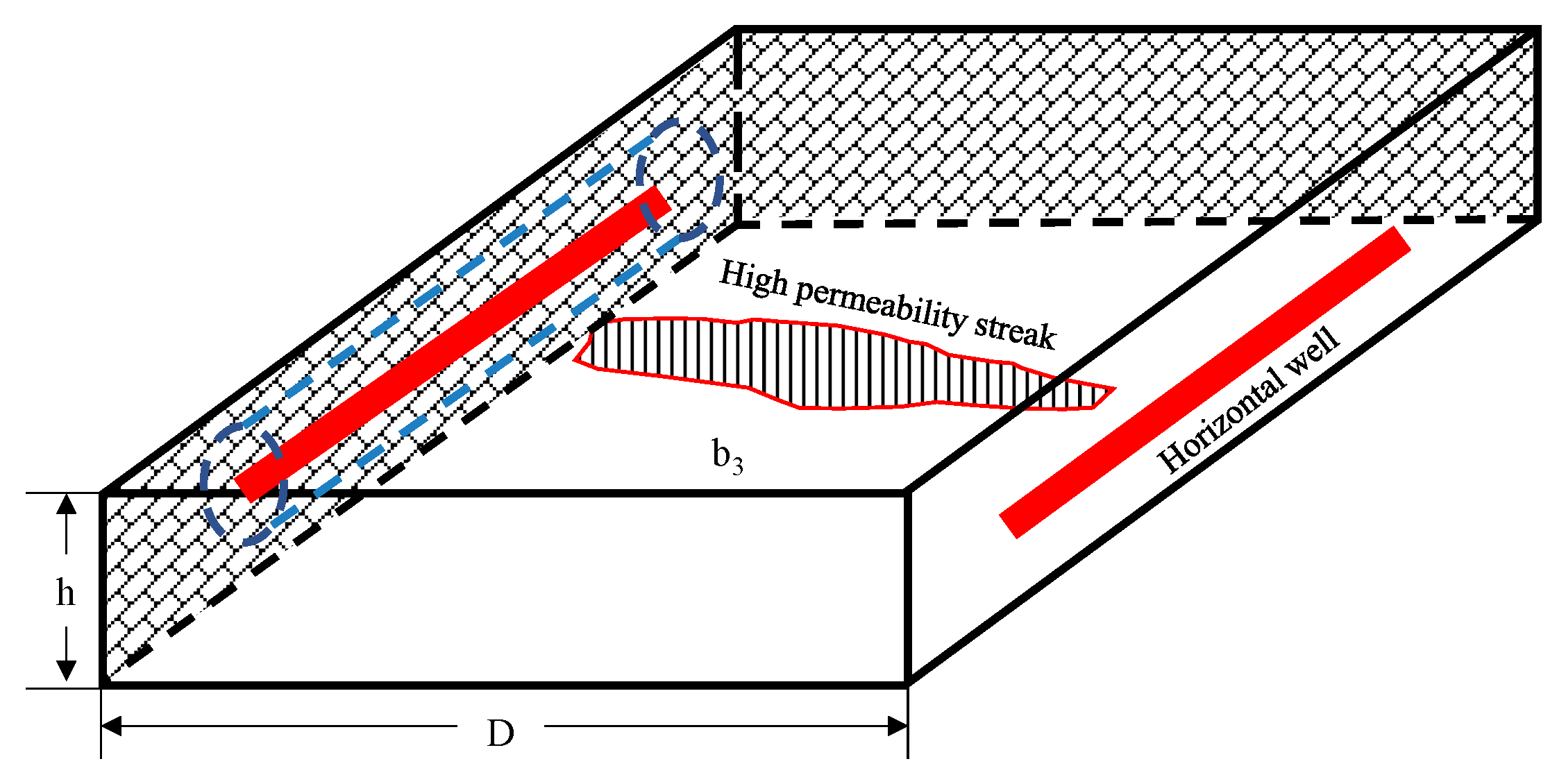
In the process of the steam stimulation of heavy oil reservoirs, including cyclic steam stimulation and the steam flooding process, steam channeling can occur within the reservoir. For CSS, it is the result of the short-term synchronous injection and production between injectors and producers (i.e., a channeling path forms between a well in the injection phase and another well in the production phase). This is the same as the counterpart of the steam flooding process in the sense that injected steam preferentially flows from the injection well towards the production well through the high-permeability pathway, leading to the phenomena of steam breakthrough. The thermal fluid continuously fingers forward in the flooding process, forming a streak-like connectivity between the injector and producer. Meanwhile, the crude oil within the high-permeability zone near the production well is preferentially swept, developing into high-permeability streaks, as shown in Figure 2. Therefore, the seepage resistance of high-permeability streaks decreases with higher oil recovery, resulting in steam fingering and steam channeling.
Considering the large well spacings of offshore heavy oil reservoirs, the thermal loss between injection and production wells could be more significant, causing the injected thermal fluid recovered from the producer to be hot water in the flooding process. According to the data of the injection–production performance, the steam flooding process could be divided into three different stages: the normal steam injection stage, the injection–production interference stage, and the injection–production channeling stage.

2.1. Normal Steam Injection Stage

During the initial period of the steam injection process, the injected steam has not yet been swept to the production wells when the well spacing is large or merely a cyclic steam stimulation (CSS) well is operated. This stage is characterized by no interaction between the injector and productor, where the flow behavior analysis could be limited to the near vicinity of the injector. According to Joshi’s productivity formula for horizontal wells,
q = 2 π K h ( p a - p w ) μ B h L ln ( h 2 π r w + S ) + ln 1 + 1 ( L / 2 a ) 2 L / 2 a
where q is the fluid production rate, m3/d; K is the effective phase permeability, mD; h is the reservoir thickness, m; pa is the average formation pressure, MPa; pw is the bottom-hole pressure, MPa; L is the well length of the horizontal section, m; μ is the fluid viscosity, mPa·s; B is the fluid volume factor, m3/m3; rw is the radius of the wellbore, m; S is the skin factor; and a is half of the major axis of a drainage ellipse in a horizontal plane where the well is located, m.
Using the method of equivalent seepage resistance, the seepage resistance of a horizontal well could be characterized as a composite radial seepage resistance, consisting of vapor-dominant near-wellbore internal radial seepage resistance and water-dominant external elliptical seepage resistance. In the normal steam injection stage, the productivity equation for the horizontal well could be expressed as follows:
q s = p w p a μ s B s 2 π K s L ln h 2 π r w + S + μ w B w 2 π K w h ln 1 + 1 ( L / 2 a ) 2 L / 2 a .
where qs is the steam injection rate with cold water equivalent, m3/d; μs and μw are the viscosities of steam and water, mPa·s; Bs and Bw are the volume factors of steam and water, m3/m3; and Ks and Kw are the effective permeabilities of steam and water, mD.
Converting the bottom-hole pressure into casing pressure, we have the following:
p w = p w c + ρ w g ( H L w ) .
where pwc is the casing pressure of the injection well, MPa; H is the vertical depth of well, m; Lw is the fluid level depth of the injection well, m; and ρw is the water density, kg/m3.
In the normal steam injection stage, the average reservoir pressure remains relatively stable and approximates the hydrostatic pressure, as shown below:
p a = ρ w g H .
Combine Equations (2)–(4), and integrate Equation (2):
p w c d τ = m 1 q s d τ + A 1 .
where
A 1 = ρ w g L w d τ
and
m 1 = μ s B s 2 π K s L ln h 2 π r w + S + μ w B w 2 π K w h ln 1 + 1 ( L / 2 a ) 2 L / 2 a .
According to Equation (7), the Hall curve (the curve between the cumulative water injected and cumulative injection pressure) could be obtained with production performance in the field, then the slope of curve could be obtained [39,40]. Based on parameters of the reservoir, injection, and well, the heated radius could be determined by the energy conservation theory to evaluate the effect of the steam injection process.

2.2. Injection–Production Interference Stage

The injection–production interference stage initiates with the pressure front of the horizontal injector reaching the producer, and it terminates with thermal fluid streaming to the producer. Since the injected thermal fluid has not reached the producer, the swept area predominately consists of the area in the near vicinity of the injector and high-permeability streaks between the injector and producer. According to the method of equivalent seepage resistance, the seepage resistance of the circular drainage area near the horizontal well is equal to that of the high-permeability streak drainage zone, which could determine the internal seepage radius. For the injection well, the relationship between the steam injection rate and pressure differential could be expressed as shown below:
q s = 2 π K s L B s μ s p w p a ln h 2 π r w + S = J s ( p w p a ) .
where Js is the steam injectivity index (cold water equivalent), m3/(d·MPa).
Substituting Equation (3) into Equation (8), the following is obtained:
q s = J s [ p w c + ρ w g ( H L w ) p a ] .
For the production well, the relationship between the oil production rate and pressure differential could be expressed as shown below:
q o = 2 π h b 3 K o B o μ o p a p p 2 π D h = J o [ p a p p c ρ o g ( H L p ) ] .
where qo is the oil production rate, m3/d; b3 is the equivalent width of the high-permeability streaks, m; pp and ppc are the bottom-hole pressure and casing pressure of the production well, MPa; Ko is the effective permeability of oil, mD; μo is the viscosity of oil, mPa·s; Bo is the volume factor of oil, m3/m3; D is the well spacing between the injector and productor, m; Lp is the fluid level depth of the production well, m; Jo is the oil productivity index, m3/(d·MPa); and ρo is the oil density, kg/m3.
Combine Equations (9) and (10) with the production–injection ratio, and integrate Equation (9). It is assumed that the production–injection ratio exhibits minimal variation in the injection–production interference stage. In addition, the densities of oil and water are approximately equal for offshore heavy oil reservoirs [41,42]. Thus, it is obtained that
[ p w c p p c + ρ w g ( L p L w ) ] d τ = m 2 q s d τ .
where
m 2 = B s μ s 2 π K s L ln h 2 π r w + S + R c t μ o B o 2 π K o h 2 π D h b 3 .
and
R c t = q o q s .
where Rct is the production–injection ratio, m3/m3.
According to Equation (11), the cumulative injection–production pressure differential (CIPPD) over the cumulative water equivalent (CWE) exhibits a linear relationship when connectivity exists between the injection and production wells. Therefore, the seepage resistance could be analyzed quantitatively by the slope of the linear relationship during the steam injection process; then, the situation of injector and the steam injectivity of the reservoir could be estimated accordingly. In addition, the slope of CIPPD over CWE could be used to quantitatively evaluate different stages of the steam flooding process.

2.3. Injection–Production Channeling Stage

In the injection–production channeling stage, the thermal fluid continuously fingers forward in the flooding process as the steam injection continues, forming a streak-like connectivity between the injector and producer. The seepage resistance of the high-permeability streak drainage zone is dominated by water in the channeling stage. Thus, the water production rate could be expressed as shown below:
q w = 2 π h b 3 K w B w μ w p p p a 2 π D h = J w [ p a p p c ρ w g ( H L p ) ] .
where Jw is the water productivity index, m3/(d·MPa).
Combine Equations (9) and (14) with the production–injection ratio, and integrate Equation (9). Similarly, it is obtained that
m 3 q s d τ = [ p w c p p c + ρ w g ( L p L w ) ] d τ .
where
m 3 = B s μ s 2 π K s L ln h 2 π r w + S + R c t μ w B w 2 π K w h 2 π D h b 3
According to Equation (16), the occurrence of inter-well channeling could be identified by the slope of CIPPD over CWE.

3. Channeling Identification Method

3.1. Construction of the Steam Channeling Identification Chart

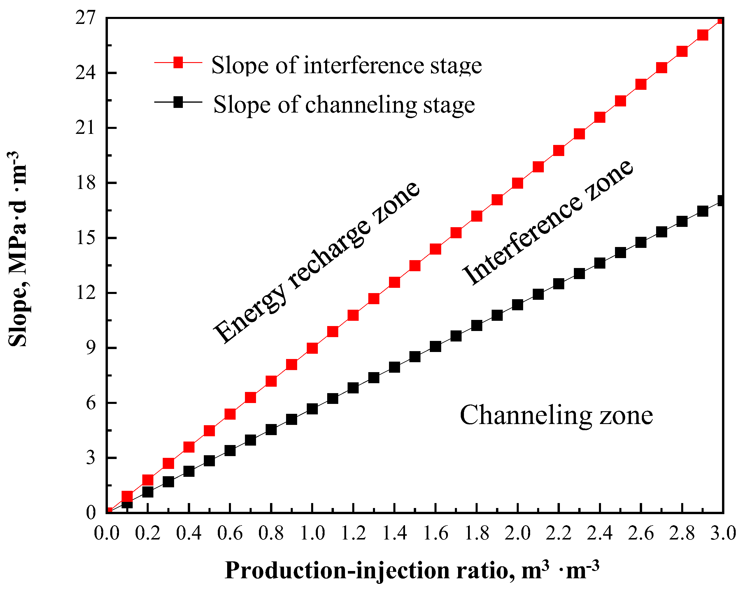
In the process of steam flooding with horizontal wells, some critical formation properties could be inversely determined by combining reservoir parameters, well parameters, and injection–production performance, which facilitates the identification of channeling between the injector and producer. For the injection–production interference stage, the slope of CIPPD over CWE differs from the counterpart of the injection–production channeling stage. According to Equations (12) and (16), the slope with varied production–injection ratios for these two stages could be calculated. As is shown in Figure 3, there are three zones in the chart, including the energy recharge zone, the interference zone, and the channeling zone.
During the process of steam flooding, the water viscosity is significantly lower than that of heavy oil; thus, the two-phase flow is dominated by water, leading to a continuous reduction in seepage resistance. Consequently, the slope value is gradually decreased with a constant production–injection ratio. From Figure 3, it is shown that the slope of the interference stage and channeling stage are increased with the increase in the production–injection ratio, which indicates that the higher the production–injection ratio, the greater the probability of inter-well channeling. In addition, the slope value of CIPPD over CWE exhibits a progressive decline trend with prolonged steam injection.

3.2. Injection–Production Performance Curve

For the steam flooding process with horizontal wells, a gradual period of injected thermal fluid reaches the producer in which the seepage resistance exhibits continuous variation. Therefore, the injection–production performance curve could be used to analyze the variation in seepage resistance. In contrast to the Hall plot merely reflecting the injectivity of a single well, the injection–production performance curve is especially applicable to investigating the inter-well connectivity [19].
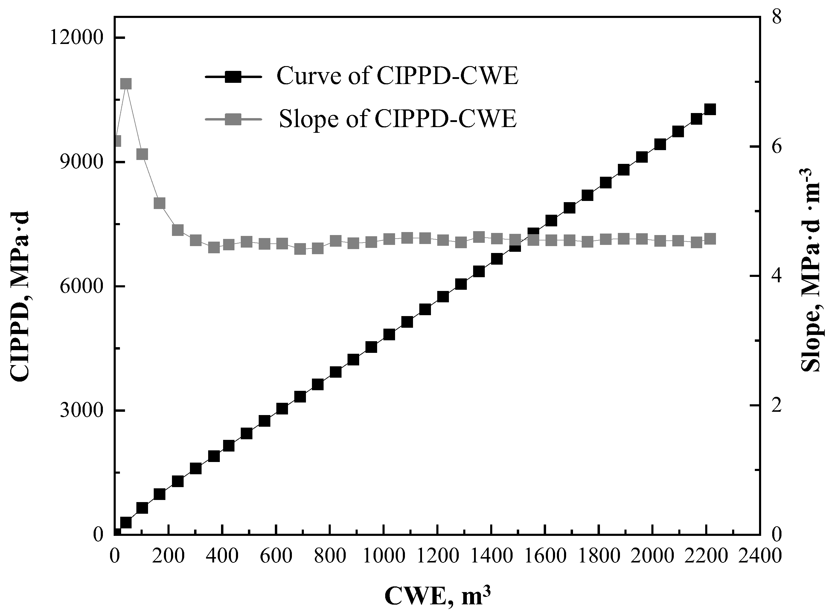
Based on the production performance in the field, the injection–production performance curve could be obtained. However, the field data are recorded daily which is discrete rather than continuous. According to the recorded data from the oilfield, the curve of CIPPD over CWE could be obtained, and the slope could be calculated by using the numerical method, as shown in Figure 4.
The curve of CIPPD over CWE could well represent the inter-well connectivity, while the slope is more sensitive to the variation in connectivity. The chart of slope with varied production–injection ratios could be obtained by scattering the slope value and production–injection ratio within the same time period, as shown in Figure 3. Thereafter, different stages could be identified by the relation between the slope value and production–injection ratio.

4. Field Application

In this section, the channeling identification chart is used to identify the occurrence of channeling for two typical wells with a steam stimulation process from the NB35-2 heavy oil reservoir in the Bohai oilfield, and the accuracy of the identification chart is validated against the field performance.

4.1. Production Performance of Typical Wells

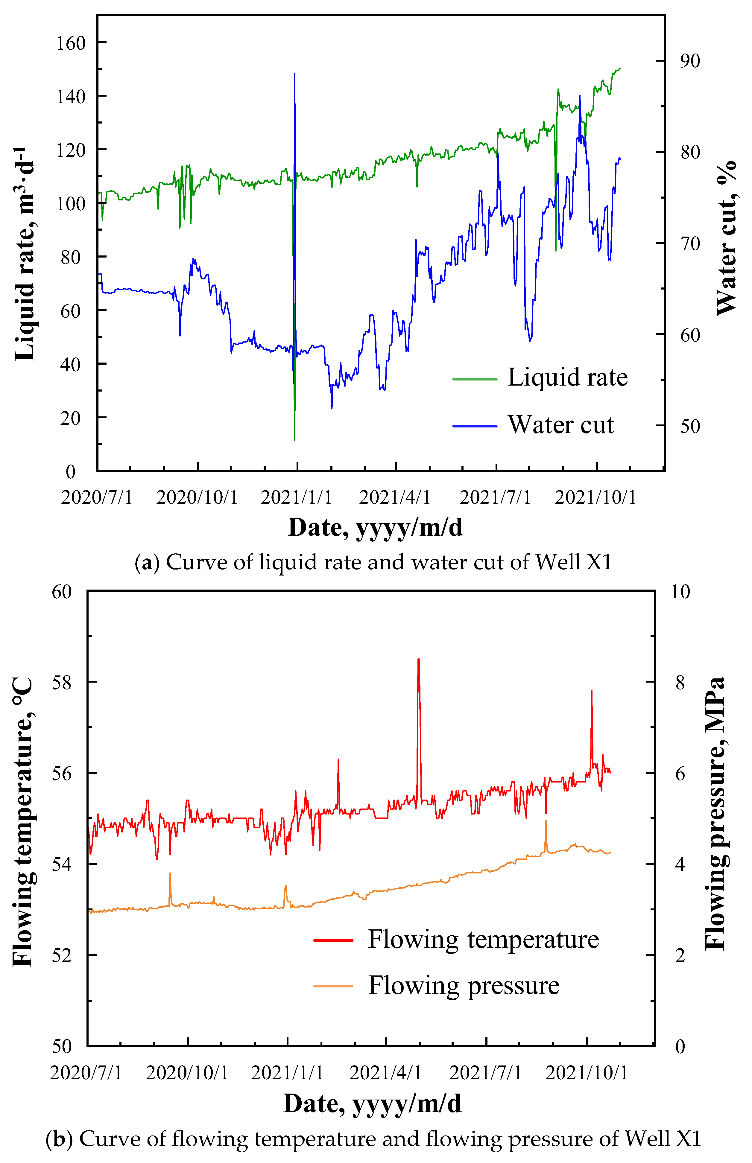
The average permeability of the NB35-2 heavy oil reservoir is 4924 mD, and the reservoir thickness is 6~8 m. The basic parameters of Well X1 are as follows: the well length of the horizontal section is 238 m; Well X1 is 100 m away from the injector; the cyclic multi-thermal fluid stimulation process is conducted prior to the steam flooding process. During the steam flooding process, the average steam injection rate of Well X1 is 281 m3/d, and the injection temperature is 300 degrees Celsius. The water cut and bottom-hole temperature of Well X1 are 67% and 54.8 °C at the initial stage of the steam flooding process. After the implementation of profile control measures in September 2020, the water cut began to decline. However, the water cut began to rise again in March 2021. Following the transition to the steam flooding process, the increase in the bottom-hole flowing temperature (BHFT) was minimal, while the water cut rose significantly, accompanied by a moderate increase in the bottom-hole flowing pressure (BHFP), as shown in Figure 5.
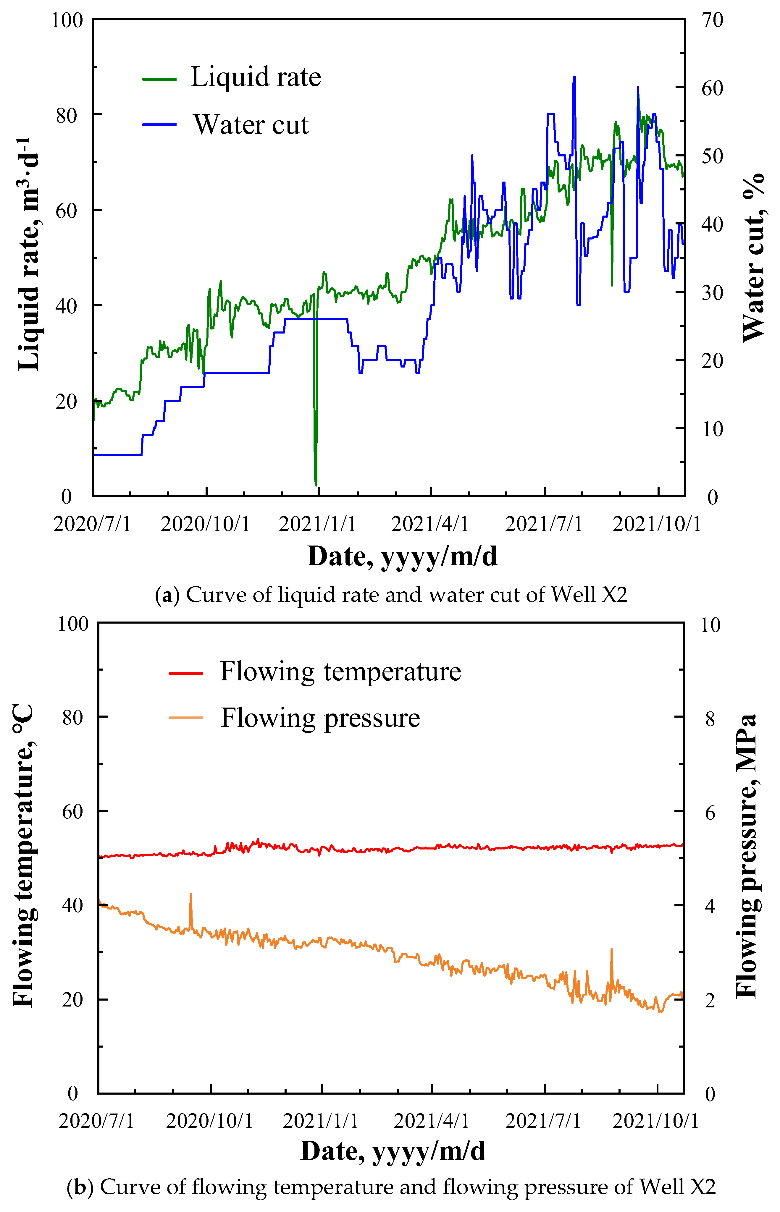
The basic parameters of Well X2 are as follows: the length of the perforation interval is 170 m; three cycles are conducted of the multi-thermal fluid huff and puff process prior to sidetracking; the well is affected by five gas channeling incidents during the multi-thermal fluid huff and puff process. Well X2 was transitioned to the steam flooding process at the end of June 2020, and the well spacing between the injector and producer was 390 m. During the steam flooding process, the average steam injection rate of Well X2 is 278 m3/d, and the injection temperature is 300 degrees Celsius. The production of the well was gradually improved by increasing the frequency of the pump at the initial stage of the steam flooding process, and the well continued to produce at a stabilized frequency of the pump at the end of August 2020. Due to the implementation of the technological measures at the end of March 2021, the seepage resistance between Well X2 and the injector decreased, which lead to an abrupt increase in the water cut and a steady increase in the liquid rate. Until October 2021, the BHFP exhibited a continuous decline throughout the steam flooding process, while BHFT showed minimal variation; in addition, the water cut increased from 6% to approximately 60%, as shown in Figure 6.

4.2. Channeling Identification of Typical Wells

Based on the production performance of Well X1 and Well X2, the curve of CIPPD and the slope over CWE could be obtained, as shown in Figure 7 and Figure 8. From Figure 7, it is shown that the slope decreases abruptly when the CWE of Well X1 reaches approximately 10,200 m3. However, the abrupt increase in the slope is due to the implementation of profile control measures when the CWE of Well X1 reached approximately 20,100 m3 in September 2021, indicating that the channeling was hindered effectively. These abrupt variations in the slope of CIPPD over CWE can be attributed to the rapid changes in seepage resistance.
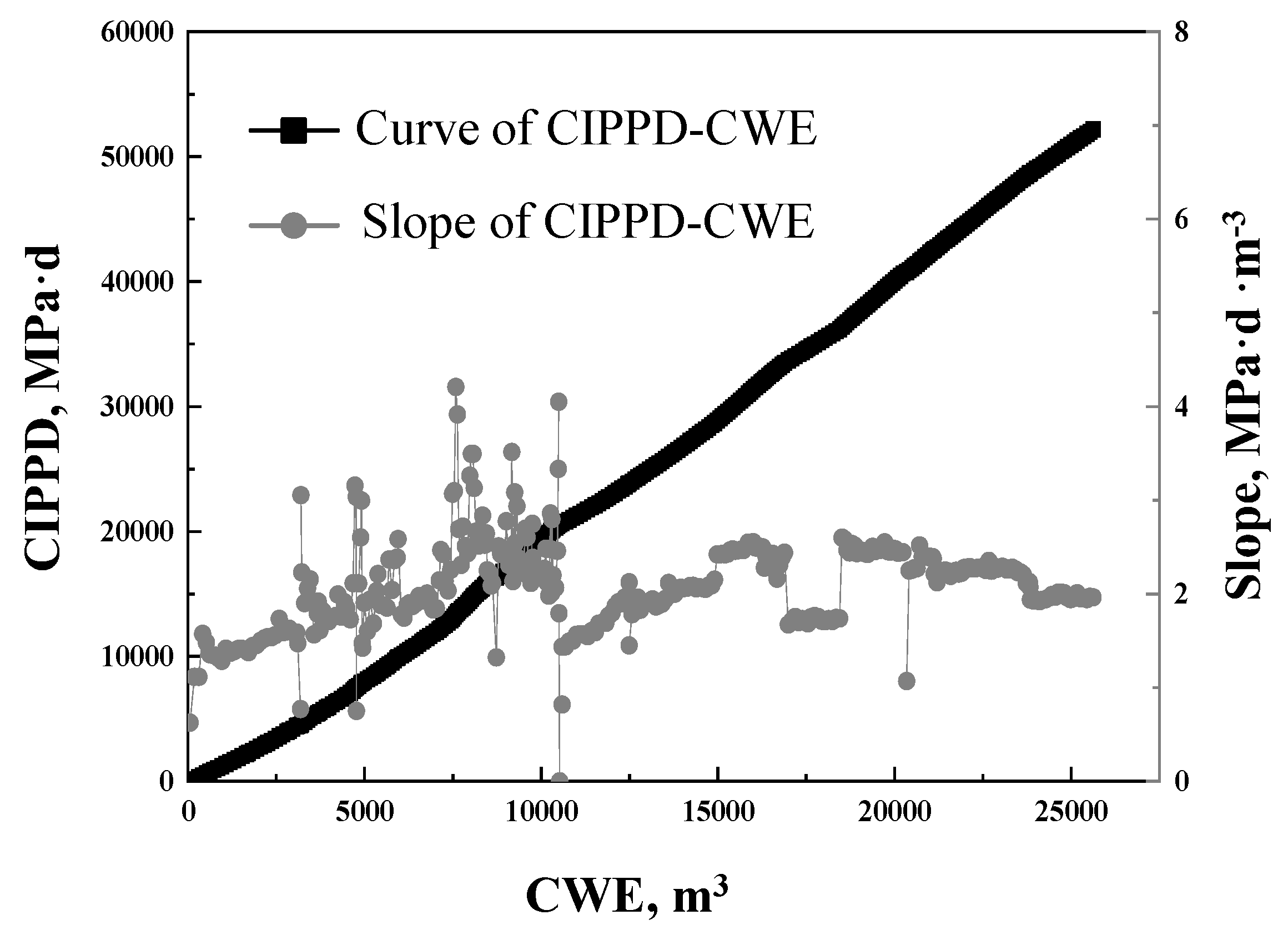
From Figure 8, it is shown that the increase in CIPPD becomes slower and the slope begins declining when the CWE of Well X2 reaches approximately 3000 m3, indicating that the inter-well seepage resistance has decreased. Similarly, the abrupt increase in the slope is due to the implementation of profile control measures when the CWE of Well X2 reaches approximately 6800 m3, indicating an obvious effect of profile control measures by increasing the seepage resistance between Well X2 and the injector.
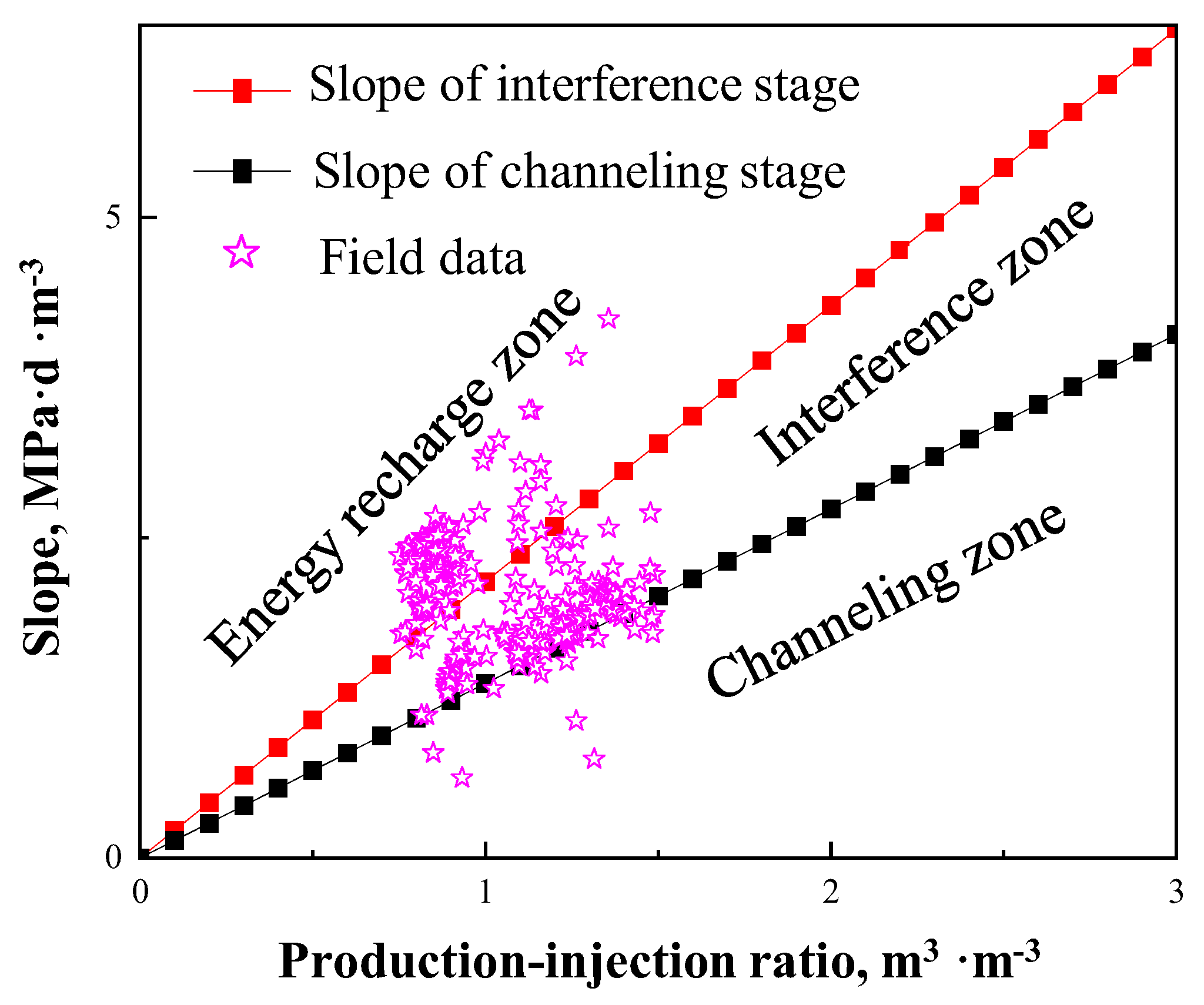
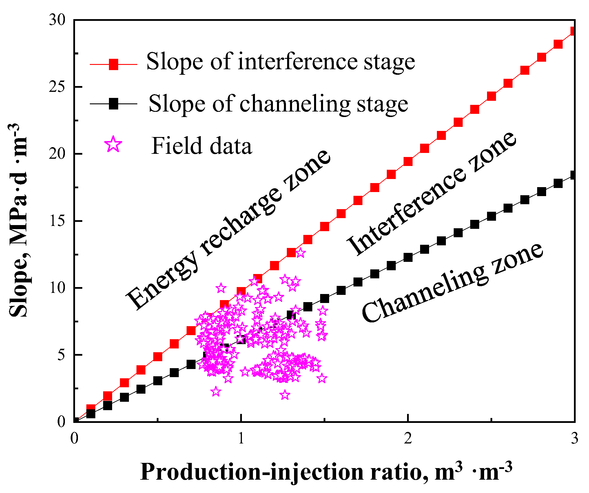
The production–injection ratio could be calculated by the performance of injection and production with the mass conservation. Thereafter, the production–injection ratio and the corresponding slope are scattered in the channeling identification chart, as shown in Figure 9 and Figure 10.
As is shown in Figure 9, most data of Well X1 are distributed in the energy recharge zone and the interference zone. However, combining Figure 7 and Figure 9, several data points scattered in the channeling zone correspond to the stage prior to the implementation of profile control measures. These results indicate that Well X1 exhibits no channeling. From Figure 5, it is shown that a moderate increase could be observed in the both liquid rate and bottom-hole pressure, confirming the result in Figure 9. The obvious variation in water cut could be attributed to the energy supplement from the near vicinity of Well X1.
From Figure 10, it is shown that most of the data for Well X2 are distributed in the interference zone and the channeling zone. As is shown in Figure 8, in the early stage of the steam flooding process, the slope of CIPPD over CWE is large, accompanied by the low water cut shown in Figure 6. Therefore, Well X2 is at the interference zone in the early stage of the steam flooding process. By combining Figure 6 and Figure 8, at the end of March 2021, the slope of CIPPD over CWE begins to decline, which is attributed to the effect of implementation of the technological measures resulting in CWE being increased (i.e., the two-phase flow is dominated by water). In addition, most slope data of Well X2 are distributed in the channeling zone after March 2021. Different from Well X1, many data scattered in the channeling zone correspond to the stage following the implementation of profile control measures, indicating the occurrence of channeling. From Figure 6, it is shown that a significant increase in the water cut (the water cut increases from 20% to 70%) and decrease in bottom-hole pressure (the pressure decreases from 3MPa to 2MPa) could be observed, confirming that channeling occurs between Well X2 and injector in the late stage of the steam flooding process.

5. Model Limitation

During the derivation of the steam channeling identification model in Section 2, we assumed that the reservoir is homogenous and isotropic. However, the effect of steam overlay is ignored. Therefore, this indicates that our model needs to be improved for heavy oil reservoirs with strong heterogeneity along the horizontal well section. Simultaneously, the application of the proposed steam channeling identification model can be extended to onshore heavy oil reservoirs with the reservoir characteristics and well pattern considered.

6. Conclusions

In this paper, a quick and widely applicable approach is proposed for channeling identification on the thermal recovery process of heavy oil reservoirs utilizing static reservoir parameters and injection–production performance, and the main conclusions drawn are as follows:
(1)
Based on the method of equivalent seepage resistance, the equations of injection performance are derived for the normal steam injection stage, injection–production interference stage, and injection–production channeling stage.
(2)
According to the derived slope expression of CIPPD over CWE for the injection–production interference stage and injection–production channeling stage, the chart of the slope with varied production–injection ratios is obtained; thus, the steam channeling identification chart is constructed. The chart consists of the energy recharge zone, the interference zone, and the channeling zone.
(3)
The illustrations of the channeling identification chart for two typical wells from the Bohai oilfield show that Well X1 exhibits no channeling and Well X2 exhibits channeling in the late stage of the steam flooding process, which are consistent with the production performance of these two actual wells.
(4)
The approach proposed in this paper is recommended for channeling identification in homogenous and isotropic reservoirs, and the effect of steam overlay is ignored. The authors also recommend applying the model to the channeling identification for onshore reservoirs by considering the reservoir characteristics and well pattern.

Author Contributions

Resources, investigation, R.Y. and L.Z.; Conceptualization, methodology, writing—review and editing, H.L. and X.D.; Investigation, writing—original draft preparation, Y.F. and T.W.; Validation, investigation, W.Z. All authors have read and agreed to the published version of the manuscript.

Funding

This research was funded by the China National Offshore Oil Corporation (Project No: KJGG2022-0604).

Data Availability Statement

The original contributions presented in the study are included in the article, further inquiries can be directed to the corresponding author.

Conflicts of Interest

Authors Renfeng Yang, Taichao Wang, Lijun Zhang and Wei Zheng were employed by the company CNOOC Research Institute Co., Ltd. The remaining authors declare that the research was conducted in the absence of any commercial or financial relationships that could be construed as a potential conflict of interest.

Nomenclature

Acronym
BHFPBottom-hole flowing pressure
BHFTBottom-hole flowing temperature
CIPPDCumulative injection–production pressure differential
CMTFSCyclic multicomponent thermal fluid stimulation
CSSCyclic steam stimulation
CWECumulative water equivalent
Sets and indices
o, s, wOil phase, steam phase, and water phase
1, 2, 3Normal injection stage, interference stage, and channeling stage
Parameters
hReservoir thickness, m
b3Equivalent width of the high-permeability streaks, m
DWell spacing between the injector and productor, m
qFluid production/injection rate, m3/d
KEffective phase permeability, mD
paAverage formation pressure, MPa
pwBottom-hole pressure, MPa
LWell length of the horizontal section, m
μFluid viscosity, mPa·s
BFluid volume factor, m3/m3
rwRadius of the wellbore, m
SSkin factor
aHalf of the major axis of a drainage ellipse in a horizontal plane, m
pwcCasing pressure of the injection well, MPa
HVertical depth of the well, m
LwFluid level depth of the injection well, m
ppBottom-hole pressure of the production well, MPa
ppcCasing pressure of the production well, MPa
LpFluid level depth of the production well, m
JProductivity index, m3/(d·MPa)
ρFluid density, kg/m3
RctProduction–injection ratio, m3/m3
mSlope of CIPPD over CWE, (d·MPa)/m3
τTime, d

References

  1. Hein, F.J. Heavy oil and oil (tar) sands in North America: An overview & summary of contributions. Nat. Resour. Res. 2006, 15, 67–84. [Google Scholar]
  2. Carpenter, C. Offshore heavy oil polymerflooding pilot reveals alternative paths. J. Pet. Technol. 2021, 73, 49–50. [Google Scholar] [CrossRef]
  3. Salimi, H.; Sieders, B.; Rostami, J. Non-isothermal compositional simulation study for determining an optimum EOR strategy for a middle-east offshore heavy-oil reservoir with compositional variations with depth. In Proceedings of the SPE EOR Conference at Oil and Gas West Asia, Muscat, Oman, 21–23 March 2022. [Google Scholar]
  4. Sun, F.; Su, Y.; Zheng, W.; Yang, R.; Zheng, Q.; Yu, J.; Yang, Z.; Wang, T. Technology progress and development direction for thermal recovery of offshore heavy oil reservoirs. China Offshore Oil Gas 2025, 37, 142–151. [Google Scholar]
  5. Tian, J. Geological Reservoir Modeling for Thermal EOR in Offshore Heavy Oil Fields: Design Practices and Case Studies; Sinopec Press: Beijing, China, 2019. [Google Scholar]
  6. Niu, J.; Huang, H.; Jiang, W. Geochemical characteristics and correlation of continuous charge mixing and biodegradation of heavy oil in southeastern Dongying Sag, Bohai Bay basin, China. J. Pet. Sci. Eng. 2018, 166, 1–12. [Google Scholar] [CrossRef]
  7. Li, Z.; Sun, Y.; Lu, T.; Hou, D.; Li, B.; Li, S. Three-Dimensional physical simulation of thermochemical flooding for offshore heavy oil. J. China Univ. Pet. (Ed. Nat. Sci.) 2020, 44, 85–90. [Google Scholar]
  8. Zhang, F.; Jiang, W.; Sun, F.; Zhou, S. Key technology research and field test of offshore viscous polymer flooding. Strateg. Study CAE 2011, 13, 28–33. [Google Scholar]
  9. Shi, L.; Liu, C.; Chen, M.; Hua, Z.; Ye, Z.; Zhang, J. Synthesis and evaluation of a hyperbranched copolymer as viscosity reducer for offshore heavy oil. J. Pet. Sci. Eng. 2021, 196, 108011. [Google Scholar] [CrossRef]
  10. Shi, C.; Meng, F.; Zhang, H.; Chang, H.; Zhong, X.; Gong, J.; Li, F. A Model for the Connectivity of Horizontal Wells in Water-Flooding Oil Reservoirs. Fluid Dyn. Mater. Process. 2022, 18, 1441–1468. [Google Scholar] [CrossRef]
  11. dos Santos Heringer, J.D.; de Souza, G.; Amaral Souto, H.P.; Pires, A.P. On the numerical simulation of non-isothermal heavy oil flow using horizontal wells and horizontal heaters. Braz. J. Chem. Eng. 2024, 41, 179–196. [Google Scholar] [CrossRef]
  12. Wang, B.; Huang, S.; Zhao, F.; Su, Z.; Fan, X.; Yang, M. Investigating the heated zone evolution and production performance of cyclic steam stimulation with horizontal well in thick-layer heavy oil reservoirs. Geoenergy Sci. Eng. 2024, 241, 213108. [Google Scholar] [CrossRef]
  13. Liu, X.; Tian, J.; Li, N.; Wang, L.; Cai, L. Economic limits of thermal recovery in offshore heavy oil reservoir. Spec. Oil Gas Reserv. 2016, 23, 106–109. [Google Scholar]
  14. Liu, X.; Zhang, F.; Huang, K.; Cui, D.; Huang, Y.; Miu, F. Discussion about the thermal recovery of NB35-2 offshore heavy oilfield. Reserv. Eval. Dev. 2011, 1, 61–63. [Google Scholar]
  15. Sun, T. Multicomponent thermal fluid recovery technology of offshore heavy oil. Chem. Eng. Manag. 2021, 18, 88–89. [Google Scholar]
  16. Cai, H.; Zou, J. Technical challenges, current situation, and prospects of thermal recovery of heavy oil in Bohai oilfield. China Offshore Oil Gas 2024, 36, 157–169. [Google Scholar]
  17. Zheng, W.; Tan, X.; Jiang, W.; Xie, H.; Pei, H. Investigation of nanoclay-surfactant-stabilized foam for improving oil recovery of steam flooding in offshore heavy oil reservoirs. ACS Omega 2021, 6, 22709–22716. [Google Scholar] [CrossRef] [PubMed]
  18. Rong, K.; Gong, R.; Huang, Z.; Liu, G. Evaluation and study of steam flooding plugging system for offshore heavy oil horizontal wells. Petrochem. Ind. Appl. 2020, 39, 14–19. [Google Scholar]
  19. Zhao, D.; Hou, J.; Sun, J.; Shi, L.; Du, Q.; Li, J. Interwell connectivity inversion method of steam flooding: Based on an analytical model and genetic algorithm. J. Pet. Sci. Eng. 2022, 215, 110641. [Google Scholar] [CrossRef]
  20. Dong, X.; Liu, H.; Chen, Z.; Wu, K.; Lu, N.; Zhang, Q. Enhanced oil recovery techniques for heavy oil and oilsands reservoirs after steam injection. Appl. Energy 2019, 239, 1190–1211. [Google Scholar] [CrossRef]
  21. Zhang, J.; Wu, Y.; Wang, C.; Liu, P.; Zhao, F.; Xi, C.; Liu, P. Synergistic improvement of sweep efficiency by urea in-situ decomposition and foaming agent in steam flooding for heavy oil reservoirs. Geoenergy Sci. Eng. 2025, 249, 213788. [Google Scholar] [CrossRef]
  22. He, Z.; Xu, H.; Ding, C. Ground steam channeling Chong32 well block and its plugging measures. Nat. Gas Explor. Dev. 2013, 36, 61–63. [Google Scholar]
  23. Huo, J.; Sang, L.; Li, J.; Zhang, Y.; Yang, Y. Using interwell electric potential monitoring technique to control surface steam breakthrough in heavy-oil reservoir of Zhong-32 Wellblock in Junggar Basin. Xinjiang Pet. Geol. 2012, 33, 495–496. [Google Scholar]
  24. Cao, X.; Wang, L.; Yu, Z. Application of tracer monitoring technology in reservoir homogeneity and reservoir connectivity. Unconv. Oil Gas 2019, 6, 71–76. [Google Scholar]
  25. Wen, S.; Xie, S.; Meng, K.; Wang, Y.; Shi, X. A fast evaluation method of water breakthrough channels based on tracer monitoring. Liaoning Chem. Ind. 2018, 47, 554–558. [Google Scholar]
  26. Liu, W.; Yi, F.; He, R.; Zhao, X. A Research and Application for a Technique of Tracer Injecting, Testing and Interpretation in Bohai Oilfields with Water-Flooding Development; China Offshore Oil and Gas: Beijing, China, 2005; pp. 245–250. [Google Scholar]
  27. Zeng, Y.; Kang, X.; Xie, X.; Shi, Y. Well-test interpretation method of the polymer-flooding high capacity channel oil reservoir. Pet. Geol. Oil Dev. Daqing 2018, 37, 130–134. [Google Scholar]
  28. Shen, W.; Zhao, H.; Liu, W.; Xu, L.; Liao, M. Identification method of dominant channeling in fractured vuggy carbonate reservoir based on connectivity model. Fault-Block Oil Gas Field 2018, 25, 459–463. [Google Scholar]
  29. Wu, M.; Xu, S.; Ding, M.; Zhao, G. Well testing interpretation model and dynamic pressure characteristics of horizontal well heavy oil thermal recovery in carbonate reservoir. Well Test. 2017, 26, 1–6. [Google Scholar]
  30. Bi, J.; Li, J.; Wu, K.; Chen, Z.; Chen, S.; Jiang, L.; Feng, D.; Deng, P. A physics-informed spatial-temporal neural network for reservoir simulation and uncertainty quantification. SPE J 2024, 28, 2026–2043. [Google Scholar] [CrossRef]
  31. Shen, L.; Li, D.; Zha, W.; Li, X.; Liu, X. Surrogate modeling for porous flow using deep neural networks. J. Pet. Sci. Eng. 2022, 213, 110460. [Google Scholar] [CrossRef]
  32. Wang, X. Research on Prediction of Steam Channeling in Steam Flooding Based on Machine Learning. Master’s Thesis, Dissertation, China University of Petroleum (East China), Dongying, China, 2022. [Google Scholar]
  33. Song, B.; Wang, R.; Ma, L.; Wei, Z.; Jia, Y.; Liu, H. Machine learning-based steam channeling identification for steam injection of heavy oil reservoirs. Oil Drill. Prod. Technol. 2022, 44, 777–783. [Google Scholar]
  34. Jeong, S.; Chung, S.; Min, B.; Kang, J.M.; Park, C. Optimal operation of Fast-SAGD process considering steam channeling among vapor chambers. In Proceedings of the ISOPE International Ocean and Polar Engineering Conference, Anchorage, Alaska, 30 June–5 July 2013. [Google Scholar]
  35. Zheng, Q.; Liu, H.; Li, F.; Wang, Q.; Wang, C.; Lu, C. Quantitative description of steam channels after steam flooding. Sci. China Technol. Sci. 2013, 56, 1164–1168. [Google Scholar] [CrossRef]
  36. Wu, K.; Li, X.; Quan, Y.; Guan, W. Forecast model for steam breakthrough during steam drive exploration of inspissated pool. Syst. Eng.—Theory Pract. 2014, 34, 538–544. [Google Scholar]
  37. Wang, X.; Qi, Y.; Zhuo, Z.; Yang, C. Exploration and application of heavy oil thermal recovery technology in offshore oilfields. Henan Sci. Technol. 2019, 5, 55–56. [Google Scholar]
  38. Vidal, P.D.C.J.; González, M.O.A.; de Vasconcelos, R.M.; de Melo, D.C.; de Oliveira Ferreira, P.; Sampaio, P.G.V.; da Silva, D.R. Decommissioning of offshore oil and gas platforms: A systematic literature review of factors involved in the process. Ocean Eng. 2022, 255, 111428. [Google Scholar] [CrossRef]
  39. Liu, Y.; Li, Y.; Jiang, S.; Li, S.; Zhang, L.; Zhang, C.; Liu, D. An application of Hall curve to thermal recovery wells in Bohai oilfields. China Offshore Oil Gas 2013, 25, 43–45. [Google Scholar]
  40. Yan, K.; Han, P.; Xie, K.; Meng, L.; Cao, W.; Cao, R.; Zhang, T.; Li, X.; Li, S. Identification and characterization of dominant seepage channels in oil reservoirs after polymer flooding based on streamline numerical simulation. Alex. Eng. J. 2024, 106, 704–720. [Google Scholar] [CrossRef]
  41. Xu, C.; Wang, B.; Wang, F.; Wan, L.; Zhang, R. Neogene extra heavy oil accumulation model and process in Liaodong Bay depression: A case study of Lvda 5-2 N oilfield. Acta Pet. Sin. 2016, 37, 599–609. [Google Scholar]
  42. Xue, Y.; Deng, Y.; Wang, D.; Yang, H.; Lv, D.; Kang, K. Hydrocarbon accumulation conditions and key exploration and development technologies for PL 19–3 oilfield. Pet. Res. 2019, 4, 29–51. [Google Scholar] [CrossRef]
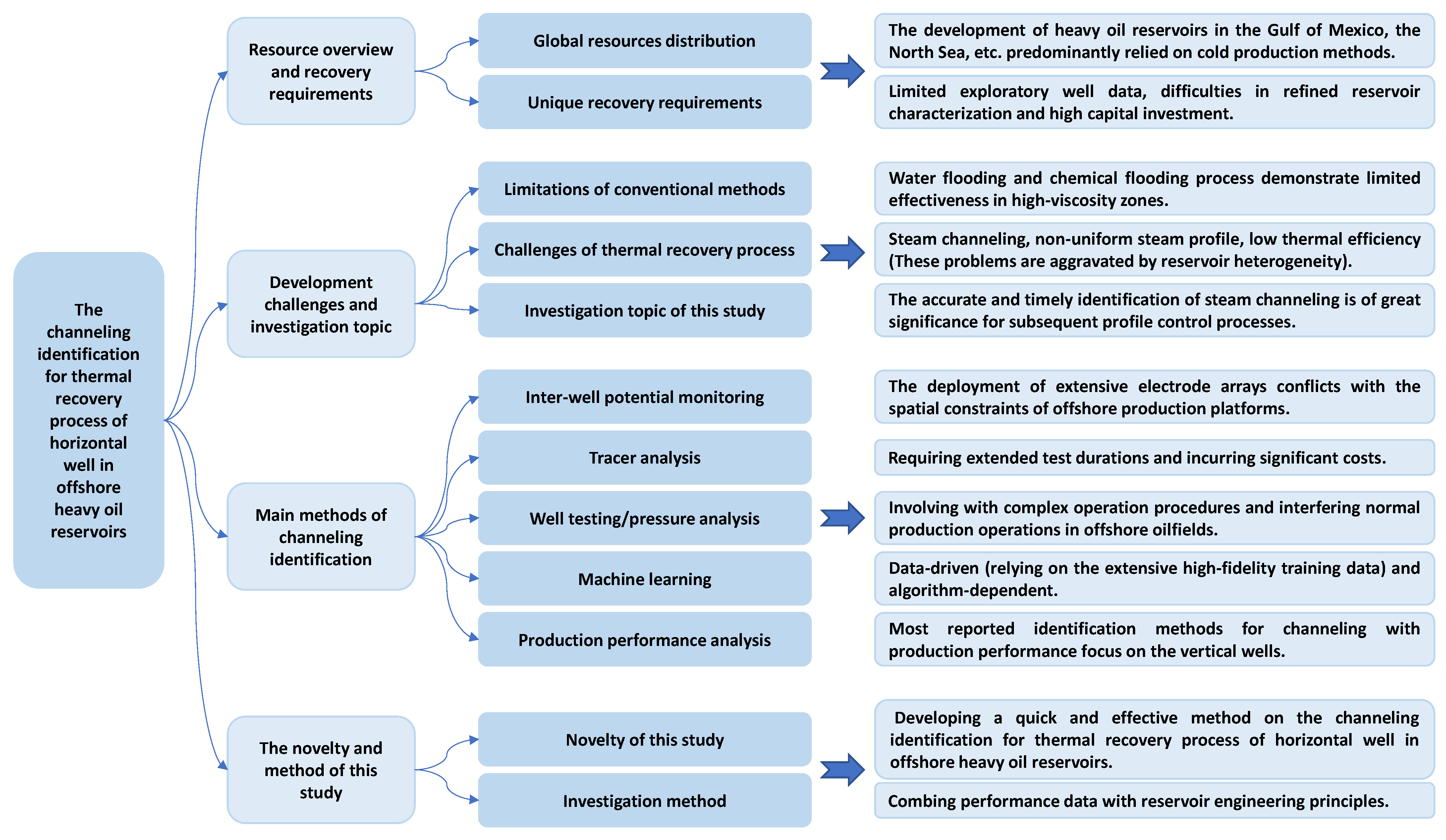
Figure 1. Flowchart outlining the topics in the introduction.
Energies 18 03450 g001
Figure 2. Schematic diagram of inter-well thermal connectivity of steam stimulation process using horizontal well. Here, h is the reservoir thickness, m; b3 is the equivalent width of the high-permeability streaks, m; D is the well spacing between the injector and productor, m.
Energies 18 03450 g002
Figure 3. Chart of CIPPD over CWE with varied production–injection ratios.
Energies 18 03450 g003
Figure 4. Curve of CIPPD and the slope over CWE.
Energies 18 03450 g004
Figure 5. Production performance of Well X1.
Energies 18 03450 g005
Figure 6. Production performance of Well X2.
Energies 18 03450 g006
Figure 7. Curve of CIPPD and the slope over CWE of Well X1.
Energies 18 03450 g007
Figure 8. Curve of CIPPD and the slope over CWE of Well X2.
Energies 18 03450 g008
Figure 9. Channeling identification chart of Well X1.
Energies 18 03450 g009
Figure 10. Channeling identification chart of Well X2.
Energies 18 03450 g010
Disclaimer/Publisher’s Note: The statements, opinions and data contained in all publications are solely those of the individual author(s) and contributor(s) and not of MDPI and/or the editor(s). MDPI and/or the editor(s) disclaim responsibility for any injury to people or property resulting from any ideas, methods, instructions or products referred to in the content.